EP0733521B1 - Electric anti-theft device - Google Patents
Electric anti-theft device Download PDFInfo
- Publication number
- EP0733521B1 EP0733521B1 EP96400553A EP96400553A EP0733521B1 EP 0733521 B1 EP0733521 B1 EP 0733521B1 EP 96400553 A EP96400553 A EP 96400553A EP 96400553 A EP96400553 A EP 96400553A EP 0733521 B1 EP0733521 B1 EP 0733521B1
- Authority
- EP
- European Patent Office
- Prior art keywords
- theft
- interruptor
- contact
- power
- key
- Prior art date
- Legal status (The legal status is an assumption and is not a legal conclusion. Google has not performed a legal analysis and makes no representation as to the accuracy of the status listed.)
- Expired - Lifetime
Links
Images


Classifications
-
- B—PERFORMING OPERATIONS; TRANSPORTING
- B60—VEHICLES IN GENERAL
- B60R—VEHICLES, VEHICLE FITTINGS, OR VEHICLE PARTS, NOT OTHERWISE PROVIDED FOR
- B60R25/00—Fittings or systems for preventing or indicating unauthorised use or theft of vehicles
- B60R25/01—Fittings or systems for preventing or indicating unauthorised use or theft of vehicles operating on vehicle systems or fittings, e.g. on doors, seats or windscreens
- B60R25/02—Fittings or systems for preventing or indicating unauthorised use or theft of vehicles operating on vehicle systems or fittings, e.g. on doors, seats or windscreens operating on the steering mechanism
- B60R25/021—Fittings or systems for preventing or indicating unauthorised use or theft of vehicles operating on vehicle systems or fittings, e.g. on doors, seats or windscreens operating on the steering mechanism restraining movement of the steering column or steering wheel hub, e.g. restraining means controlled by ignition switch
-
- B—PERFORMING OPERATIONS; TRANSPORTING
- B60—VEHICLES IN GENERAL
- B60R—VEHICLES, VEHICLE FITTINGS, OR VEHICLE PARTS, NOT OTHERWISE PROVIDED FOR
- B60R25/00—Fittings or systems for preventing or indicating unauthorised use or theft of vehicles
- B60R25/01—Fittings or systems for preventing or indicating unauthorised use or theft of vehicles operating on vehicle systems or fittings, e.g. on doors, seats or windscreens
- B60R25/04—Fittings or systems for preventing or indicating unauthorised use or theft of vehicles operating on vehicle systems or fittings, e.g. on doors, seats or windscreens operating on the propulsion system, e.g. engine or drive motor
Definitions
- the present invention relates to an electric anti-theft device, especially for a motor vehicle.
- a control unit When the access management system recognizes the right and an access request, a control unit produces an actuation order which excites the motor organ electric.
- the lock and / or the lock changes state while passing from the locked state to the unlocked state.
- Reverse analog sequence occurs for output and / or activation of the anti-theft device.
- the vehicle in a phase of deactivation of the lock, the vehicle is accessed, for example with a remote control, we operate a switch which reproduces the handling of the usual mechanical keys, a determined position of the switch to produce a identification request for unlocking request anti-theft device, and in response an activation order of successive switch positions and an order of unlocking the lock.
- An electric lock must give the user the same security than a conventional mechanical control lock by key and must in particular prevent any vehicle starting as long as the anti-theft blocking device is not in the unlocked position.
- the present invention aims to provide an anti-theft device electric of the type mentioned above which meets these security requirements.
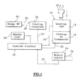
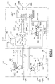
- the electric anti-theft system shown diagrammatically in FIG. 1 comprises, in accordance with the teachings of the state of the art, a key 10, or a false key, which is intended to come get into the barrel, or into a fake cannon, of a anti-theft switch 12.
- Switch 12 is provided to equip the switchboard edge of the vehicle and its design is of substantially the type close to that of the vehicle start switch according to the state of the art.
- the user operates the ignition key 10, or a ignition ring simulating such an operation.
- the key to contact 10 is in fact a false key in that it does not act necessarily on a mechanical lock, although such real key provides an additional level of security adding a locking or unlocking means additional in chain with the general design of a electric lock.
- the anti-theft switch 12 includes a key 14 which is intended to detect the absence of key 10 or the presence in the introduced position of the latter.
- the switch 12 also includes a switch for multi-position control 16 for controlling the starting the vehicle engine and for controlling the supply of various electrical circuits of the vehicle, and especially the ignition circuit of the combustion engine.
- the key switch 14 is connected by a line 18 to a input of a central anti-theft device 20 while the command 16 is connected to a line 22 by another input of the anti-theft control unit 20.
- the anti-theft system has an analysis circuit which is especially able to read the positions occupied by switches 14 and 16 of switch 12.
- the anti-theft system includes for example a microcontroller such as an INTEL 8051. circuit contains a program for reading the input ports for inform the central anti-theft system of the positions of the different switch 12 switches as will be explained by the following.
- a microcontroller such as an INTEL 8051. circuit contains a program for reading the input ports for inform the central anti-theft system of the positions of the different switch 12 switches as will be explained by the following.
- the central anti-theft system 20 can exchange signals with an interrogation and reception station 24 which exchange, by lines 26 and 28 of the signals with by example of a badge 30 for access without a key to the vehicle.
- the central anti-theft device 20 triggers a means forgetfulness alarm 38.
- the key switch 14 has a movable contact rocker 42 which is permanently connected to the -BAT terminal of the vehicle battery and whose free end cooperates with a fixed contact 44 in the absence of a key, or with a fixed contact 46 when a key 10 is entered in the switch command 12 or when such an introduction is simulated.
- the key switch 14 is associated in parallel with a complementary key switch 48 which includes a movable contact 50 which moves simultaneously with the movable contact 42 of the key switch 14.
- the movable contact 50 is permanently connected, by the line 18, at the "REQUEST" entry port of the central anti-theft system 20 of so that the latter can trigger a sequence identification of the anti-theft unlocking request or of the anti-theft lock request.
- the movable contact 50 of the key switch complementary 48 is likely to cooperate with a fixed contact 52 in the presence of a key, as is particularly shown in Figure 3, so as to connect electrically the "REQUEST" input of the central anti-theft system 20 to the -BAT polarity of the vehicle battery.
- the movable contact 50 cooperates with a fixed contact 54 which is a neutral contact and the input port "REQUEST" is not connected to any polarity of the battery of the vehicle.
- the multi-position control switch 16 is a rotary type switch which has a movable contact 56 which is permanently connected to the + BAT terminal of the vehicle battery.
- the mobile control contact 56 is susceptible successively occupy several offset positions angularly with respect to each other and which are marked “0”, “ACC", "M” and “D” in the figures.
- the movable contact 56 When the movable contact 56 is in the ACC position, it cooperates with a fixed track 58 which is electrically connected to the supply system + ACC for vehicle accessories.
- the movable control contact 56 When the movable control contact 56 is in the position M, it is simultaneously in contact with runway 58 and with a conductive track 60 which is connected to the circuit ignition + ALL of the vehicle engine with interposition of a inhibition device 64.
- the motorized anti-theft motor 34 is an electric motor whose opposite terminals A1 and A2 are connected to a block 68 motor power supply 34.
- a first terminal B1 of the power supply unit is connected permanently at the + BAT terminal of the vehicle battery while its second terminal B2 is permanently connected to a V / D input of the central anti-theft device 20 which is an input of detection of change of state of this second terminal B2.
- the second terminal B2 of power supply 68 is also connected to terminal - BAT of the vehicle battery via the key switch 14 and power switches 70.
- Power supply 68 receives control commands of the supply of the motor 34, with a view to causing its unlocking or locking by lines 72D and 72V connected to DEV and VER output ports of the control panel lock 20.
- the motor 34 is likely to turn in either direction between a lock position which is determined by a mechanical locking stop 74 with which is capable of cooperating with a linked mechanical stop member 76 rotating at the output shaft of the motor 34, and a position lock release angle determined by a mechanical unlocking stop 78.
- These switches consist of a movable contact common rotary 80 which is linked in rotation to the output shaft of the motor 34, by a mechanical connection illustrated by the line at dotted line 82.
- the rotary movable contact 80 is susceptible whether or not to cooperate with a first fixed contact 84 made in the form of a conductive track which is connected to the first fixed contact 44 of the key switch 14 via a line 85.
- the first power switch 80, 84 is open when the lock is in the locked position and it is closed to all other lock positions.
- the second power switch of terminal B2 is constituted by the rotary contact 80 which is capable of cooperate with a second fixed contact 86 produced in the form a conductive track permanently connected to the second fixed contact 46 of the key switch 14 via a line 87.
- the second power switch 80, 86 is not open only when the lock is in the unlocked position and it is closed for all other anti-theft positions.
- the anti-theft system 20 also has a port M1V input for detecting the locked status of the lock and a M2D input port to detect the unlocked state of the lock.
- M1V and M2D input ports are connected to means 88 for detecting the status of the lock.
- the means 88 of anti-theft status detection include a switch 90 detection of the locking of the anti-theft device comprising a contact mobile 92 which is permanently connected to the -BAT terminal of the vehicle battery and which, when the lock is in position locked, cooperates with a fixed contact 94 which is connected in permanence at the M1V input of the central anti-theft system 20.
- the movable contact 92 of the switch 90 for detecting the anti-theft lock cooperates with a fixed neutral contact 96.
- the means 88 for detecting the state of the anti-theft device also include a switch 98 for detecting the unlocking the anti-theft device which includes a movable contact 100 which is permanently connected to the -BAT terminal of the battery vehicle and which cooperates with a fixed neutral contact 102 when the lock is not in the unlocked position and which cooperates with a fixed contact 104 which is permanently connected at the M2D input of the central anti-theft system 20, when the anti-theft system is in the unlocked position.
- the anti-theft control unit is connected by a coded link 106 to the other components of the electric lock and by a link 108 to diagnostic means.
- the inhibition device 64 is, in this first mode of realization, constituted by a rotary switch which comprises a movable rotary inhibition contact 110 which is connected at permanence at the conductive track 60 of the switch multi-position control 16 and which only in unlocked position of the lock, is likely to cooperate with a fixed stud 112 connected to the electrical circuit + ALL of the vehicle engine ignition circuit.
- the movable rotary inhibition contact 110 is connected to the motor output shaft 34 by a link mechanical represented by the dashed line 114 of the figure 2.
- the first power switch 80, 84 is open while the second power switch 80, 86 is closed.
- the second terminal B2 of block 68 of the electric motor 34 is not connected to the -BAT terminal of the vehicle battery.
- the driver When the driver inserts the key 10 into the switch 12, or when it simulates such an introduction, it first causes the key switch to change state 14 which passes from the position illustrated in FIG. 2 to the position illustrated in figure 3.
- the movable contact 42 is in contact with contact 46 and it thus establishes a connection between the second terminal B2 of the power supply 68 and the -BAT terminal of the vehicle battery via line 87 and by the second power switch 80, 86 which is closed.
- the complementary switch 48 Simultaneously with the change of position of the key switch 14, the complementary switch 48 a changed position and his mobile contact 50 established the connection between the REQUEST input port of the control panel anti-theft device 20 and the -BAT terminal of the vehicle battery.
- this port of entry has received an order which is analyzed by the central anti-theft system 20 as an order of anti-theft unlocking control.
- the central anti-theft system 20 transmits an order to power supply 68, via line 72D of the start of the unlocking which causes the setting in rotation, clockwise considering Figure 3, motor 34.
- Mute switch 64 is always open and is not not possible to cause the engine to start vehicle.
- the second switch supply 80, 86 opens and the second terminal B2 of the block 68 is no longer connected to the -BAT terminal of the vehicle battery, causing the engine 34 to stop unlocked lock position.
- the anti-theft unlocking detection switch 98 changes position and transmits a signal corresponding to the M2D input port of the central anti-theft system which is connected to the -BAT terminal of the vehicle battery.
- the muting switch 64 is closed and the vehicle engine ignition circuit is powered because it is connected to the + BAT terminal of the battery by the mobile control contact 56 when it is opposite of the conductive track 60.
- the driver can therefore cause the starting of the engine and continue using it.
- the change in position of the movable contact 50 from the complementary switch 48 again causes a change of state at the REQUEST input of the central anti-theft device which analyzes a change of state as a request from the anti-theft locking system and the central anti-theft system 20 transmits then a corresponding lock order command by 72V line to power supply 68.
- the second terminal B2 of the power supply 68 is connected to the -BAT terminal of the vehicle battery by the first power switch 80, 84 which is closed, by line 85 and by the tilting movable contact 42 of the key switch 14.
- the locking control command transmitted to power supply 68 through line 72V can be run and counterclockwise rotation when considering figure 6, engine 34 can start.
- the motor 34 rotates counterclockwise and continues until it comes again occupy its angular locking position illustrated on the figure 2.
- the lock detection switch 90 When this locking position is again reached, the lock detection switch 90 has again changed position by transmitting information corresponding to the M1V input of the anti-theft control unit 20, any new request to the central anti-theft system 20 at its REQUEST input port thus being subsequently analyzed as an unlock request request from the lock.
- the variant embodiment illustrated in FIG. 8 differs of the first embodiment illustrated in Figures 2 to 7 only in that the movable contact 92 of the switch 90 lock detection system is not directly connected to the -BAT terminal of the battery, because it is connected directly at the first fixed contact 44 of the key switch 14.
- the movable contact 100 of the switch 98 of detection of the anti-theft unlocking is connected directly to the second fixed contact 46 of the key switch 14.
- This second embodiment differs from the first embodiment embodiment illustrated in Figures 2 to 7 first of all by the structure means of inhibition.
- the contact rotary control mobile 56 is connected by a line 116 to the fixed pad 112 of the muting switch 64 whose contact rotary muting mobile 110 is permanently connected to the pole + BAT of the battery.
- circuits + DEM, + ALL and + ACC of the vehicle cannot be powered electrically, by the cooperation of the mobile control contact 56 with the track corresponding 62, 60 or 58, only when the switch muting 64 is closed, i.e. when the lock is unlocked.
- the second embodiment illustrated in Figures 9 to 14 also differs from the first embodiment by the structure power switches and power switches detection of the locking and unlocking of the anti-theft device which are common here.
- the first power switch consists of a mobile contact 80-92 which is likely to cooperate with a fixed contact 84 connected to terminal B2 of power supply 68 or with a fixed contact 94 connected to the M1V input of the control panel anti-theft device 20 so as to constitute a switch 90 of anti-theft lock detection.
- the second power switch consists of a mobile contact 80-100 which is susceptible to cooperate with a contact 86 connected to terminal B2 of the block 68 or with a fixed contact 104 connected to the input M2D of the central anti-theft system 20.
Description
La présente invention concerne un antivol électrique, notamment pour un véhicule automobile.The present invention relates to an electric anti-theft device, especially for a motor vehicle.
Il a déjà été proposé des dispositifs permettant de déverrouiller à distance, et donc sans contact, ni électrique, ni mécanique, les ouvrants d'un objet et notamment d'un véhicule automobile.Devices have already been proposed enabling unlock from a distance, and therefore without contact, neither electrical nor mechanical, the opening of an object and in particular of a vehicle automobile.
En particulier, on a développé des techniques d'accès sans clef qui permettent d'accéder à des ressources sans avoir à sortir une clef mécanique, ou équivalente, d'autorisation de l'accès.In particular, we have developed access techniques without keys that allow access to resources without having to take out a mechanical key, or equivalent, for authorization to access.
Un tel système est très attractif par le confort qu'il apporte à l'usager et par les possibilités de gestion des accès par des moyens informatisés qu'il permet.Such a system is very attractive for the comfort it provides to the user and by the possibilities of access management by computerized means that it allows.
Dans l'application au verrouillage et au déverrouillage d'ouvrants comme ceux d'un véhicule automobile, ou d'un antivol de sécurité comme celui d'une colonne de direction ou de l'arbre de sortie de la boíte de vitesses d'un véhicule, on a, dans cette optique, proposé des systèmes mécaniques utilisant des organes moteurs de type électrique tels qu'un moteur électrique tournant ou un électro-aimant.In the application for locking and unlocking openings such as those of a motor vehicle, or a security lock such as a steering column or of the output shaft of the gearbox of a vehicle, we have, in this perspective, proposed mechanical systems using electric type drive members such as an engine electric rotating or an electromagnet.
Quand le système de gestion des accès reconnaít le droit d'accès et une demande d'accès, un organe de commande produit un ordre d'actionnement qui excite l'organe moteur électrique. L'antivol et/ou le verrou change d'état en passant de l'état verrouillé à l'état déverrouillé.When the access management system recognizes the right and an access request, a control unit produces an actuation order which excites the motor organ electric. The lock and / or the lock changes state while passing from the locked state to the unlocked state.
Une séquence analogue inverse se produit pour la sortie et/ou l'activation de l'antivol.Reverse analog sequence occurs for output and / or activation of the anti-theft device.
Selon une conception connue, décrite et représentée dans le document FR-A-2.710.599 (non publié à la date de priorité du présent brevet), il a déjà été proposé un procédé de contrôle d'un antivol de véhicule automobile, notamment avec système d'accès par commande à distance, faisant notamment appel à un commutateur de commande du démarrage et d'alimentation électrique de différents circuits électriques du véhicule et notamment d'un circuit d'alimentation des accessoires et du circuit d'allumage du moteur du véhicule. Un autre état de la technique est constitué par le document US-A-3.735.833.According to a known concept, described and represented in document FR-A-2.710.599 (not published on the priority date of this patent), a method has already been proposed control of a motor vehicle anti-theft device, in particular with remote control access system, including call to a start control switch and power supply of different electrical circuits of the vehicle and in particular a power supply circuit for vehicle engine ignition system. A another state of the art is constituted by document US-A-3,735,833.
Selon le procédé, dans une phase de désactivation de l'antivol, on accède au véhicule, par exemple avec une télécommande, on manoeuvre un commutateur qui reproduit la manipulation des clefs mécaniques habituelles, on détecte une position déterminée du commutateur pour produire une interrogation d'identification de la demande de déverrouillage de l'antivol, et on produit en réponse un ordre d'activation de positions successives du commutateur et un ordre de déverrouillage de l'antivol.According to the method, in a phase of deactivation of the lock, the vehicle is accessed, for example with a remote control, we operate a switch which reproduces the handling of the usual mechanical keys, a determined position of the switch to produce a identification request for unlocking request anti-theft device, and in response an activation order of successive switch positions and an order of unlocking the lock.
Dans une phase d'activation de l'antivol, on détecte une manoeuvre d'activation de l'antivol sur le commutateur, cette manoeuvre reproduisant les manipulations habituelles des clefs mécaniques, on active l'antivol, on désactive les positions successives du commutateur.In an anti-theft activation phase, a anti-theft activation operation on the switch, this maneuver reproducing the usual manipulations of mechanical keys, we activate the lock, we deactivate them successive switch positions.
Pour la mise en oeuvre d'un tel procédé, il est fait appel à un antivol électrique du type comportant :
- un commutateur d'antivol pour l'alimentation de différents circuits électriques du véhicule ;
- un antivol motorisé comportant un moteur électrique d'entraínement d'un organe de blocage entre une position verrouillée et une position déverrouillée ;
- et une centrale d'antivol connectée aux éléments précédents pour mettre en oeuvre un procédé de contrôle de l'antivol ;
- un interrupteur de clef pour détecter la simulation de l'introduction d'une clef dans le commutateur d'antivol ;
- et un interrupteur de commande à positions multiples pour commander en séquence l'alimentation desdits circuits électriques du véhicule, comportant un contact mobile de commande relié à une polarité d'une source d'alimentation, et une série de contacts fixes avec lesquels le contact mobile entre successivement en contact lors de la manoeuvre du commutateur en vue de provoquer le démarrage du véhicule, l'interrupteur de commande ne pouvant être actionné qu'en présence d'une clef.
- an anti-theft switch for supplying various electrical circuits of the vehicle;
- a motorized anti-theft device comprising an electric motor driving a blocking member between a locked position and an unlocked position;
- and an anti-theft control unit connected to the above elements to implement a method of controlling the anti-theft;
- a key switch for detecting the simulation of the introduction of a key into the anti-theft switch;
- and a multi-position control switch for sequentially controlling the supply of said electrical circuits of the vehicle, comprising a movable control contact connected to a polarity of a power source, and a series of fixed contacts with which the movable contact successively comes into contact when the switch is operated in order to cause the vehicle to start, the control switch can only be actuated in the presence of a key.
Un antivol électrique doit conférer à l'usager la même sécurité qu'un antivol à commande classique mécanique par clef et doit notamment empêcher tout démarrage du véhicule tant que l'organe de blocage de l'antivol n'est pas dans la position déverrouillée.An electric lock must give the user the same security than a conventional mechanical control lock by key and must in particular prevent any vehicle starting as long as the anti-theft blocking device is not in the unlocked position.
De préférence, il doit aussi éviter toute possibilité d'activation de l'antivol vers sa position verrouillée tant que le véhicule n'est pas arrêté.Preferably, he should also avoid any possibility activating the lock to its locked position as long as the vehicle is not stopped.
La présente invention a pour but de proposer un antivol électrique du type mentionné précédemment qui réponde à ces impératifs de sécurité.The present invention aims to provide an anti-theft device electric of the type mentioned above which meets these security requirements.
Dans ce but, l'invention propose un antivol caractérisé en
ce que l'un au moins des circuits électriques du véhicule est
relié à une polarité de la source d'alimentation à travers
l'interrupteur de commande à positions multiples et à travers
un dispositif d'inhibition qui n'établit l'alimentation électrique
de ce circuit que lorsque l'antivol est en position déverrouillée ;
et en ce que l'interrupteur de clef comporte un contact
mobile relié à la source d'alimentation et qui est susceptible :
- de coopérer avec un premier contact fixe relié au moteur d'entraínement de l'antivol motorisé en l'absence de clef et à travers un premier interrupteur d'alimentation qui est ouvert lorsque l'antivol est en position verrouillée ;
- ou de coopérer avec un second contact fixe relié au moteur d'entraínement de l'antivol motorisé en présence de clef et à travers un deuxième interrupteur d'alimentation qui est ouvert lorsque l'antivol est en position déverrouillée ;
- le dispositif d'inhibition est un interrupteur d'inhibition dont le contact mobile est relié audit contact fixe de l'interrupteur de commande et coopère avec un plot fixe relié audit circuit électrique lorsque l'antivol est en position déverrouillée ;
- le contact mobile de commande de l'interrupteur de commande à positions multiples du commutateur d'antivol est relié à une polarité de la source d'alimentation par un dispositif d'inhibition qui n'établit la liaison électrique que lorsque l'antivol est en position déverrouillée ;
- le dispositif d'inhibition est un interrupteur d'inhibition dont le contact mobile est relié à une polarité de la source d'alimentation et coopère avec un plot fixe relié au contact mobile de commande lorsque l'antivol est en position déverrouillée ;
- le contact mobile de l'interrupteur d'inhibition est lié en rotation au moteur de l'antivol motorisé ;
- le premier interrupteur d'alimentation est constitué par un contact mobile relié en permanence au moteur et qui est susceptible de coopérer avec un premier plot fixe relié au premier contact fixe de l'interrupteur de clef lorsque le premier interrupteur d'alimentation est fermé ;
- le second interrupteur d'alimentation est constitué par un contact mobile relié en permanence au moteur et qui est susceptible de coopérer avec un second plot fixe relié au second contact fixe de l'interrupteur de clef lorsque le second interrupteur d'alimentation est en position fermée ;
- lesdits premier et second plots fixes sont des pistes conductrices décalées et ledit contact mobile est un contact mobile commun au premier et second interrupteurs d'alimentation et qui est lié en rotation au moteur électrique ;
- l'entrée, de la centrale d'antivol, de détection d'un changement de position du contact mobile de l'interrupteur de clef est reliée à une polarité de la source d'alimentation à travers un interrupteur dont le contact mobile se déplace simultanément avec le contact mobile de l'interrupteur de clef et qui est fermé en l'absence de clef ;
- les moyens de détection de l'état d'antivol comportent :
- un interrupteur de détection du verrouillage de l'antivol comportant un contact mobile relié à une polarité de la source d'alimentation et qui est susceptible de coopérer avec un contact fixe, relié à l'entrée de détection de l'état verrouillé de l'antivol, lorsque l'antivol est en position verrouillée ; et
- un interrupteur de détection du déverrouillage de l'antivol comportant un contact mobile relié à une polarité de la source d'alimentation et qui est susceptible de coopérer avec un contact fixe, relié à l'entrée de détection de l'état déverrouillé de l'antivol, lorsque l'antivol est en position déverrouillée ;
- le contact mobile de l'interrupteur de détection du verrouillage de l'antivol est relié audit premier contact fixe de l'interrupteur de clef et le contact mobile de l'interrupteur de détection du déverrouillage de l'antivol est relié au second contact fixe de l'interrupteur de clef ;
- le contact mobile de l'interrupteur de détection du verrouillage de l'antivol est constitué par le contact mobile du premier interrupteur d'alimentation qui est susceptible de coopérer avec un contact fixe, relié à l'entrée de détection de l'état verrouillé de l'antivol, lorsque le premier interrupteur d'alimentation est ouvert, et le contact mobile de l'interrupteur de détection du déverrouillage de l'antivol est constitué par le contact mobile du second interrupteur d'alimentation qui est susceptible de coopérer avec un contact fixe, relié à l'entrée de détection de l'état déverrouillé de l'antivol, lorsque le second interrupteur d'alimentation est ouvert ;
- l'antivol comporte un bloc d'alimentation électrique du moteur qui reçoit, de la centrale d'antivol, des ordres de commande du verrouillage ou du déverrouillage de l'antivol, une première borne du bloc d'alimentation est reliée en permanence à une première polarité de la source d'alimentation, et la seconde borne du bloc d'alimentation est susceptible d'être reliée à la seconde polarité de la source d'alimentation à travers l'interrupteur de clef et l'un ou l'autre des premier et second interrupteurs d'alimentation ;
- le commutateur est un commutateur rotatif.
and in that the key switch comprises a movable contact connected to the power source and which is capable of:
- to cooperate with a first fixed contact connected to the drive motor of the motorized anti-theft device in the absence of a key and through a first power switch which is open when the anti-theft device is in the locked position;
- or cooperate with a second fixed contact connected to the drive motor of the motorized anti-theft device in the presence of a key and through a second power switch which is open when the anti-theft device is in the unlocked position;
- the inhibition device is an inhibition switch whose movable contact is connected to said fixed contact of the control switch and cooperates with a fixed stud connected to said electrical circuit when the anti-theft device is in the unlocked position;
- the movable control contact of the multi-position control switch of the anti-theft switch is connected to a polarity of the power source by an inhibition device which establishes the electrical connection only when the anti-theft device is in unlocked position;
- the inhibition device is an inhibition switch whose movable contact is connected to a polarity of the power source and cooperates with a fixed stud connected to the movable control contact when the anti-theft device is in the unlocked position;
- the movable contact of the muting switch is linked in rotation to the motor of the motorized anti-theft device;
- the first power switch is constituted by a movable contact permanently connected to the motor and which is capable of cooperating with a first fixed stud connected to the first fixed contact of the key switch when the first power switch is closed;
- the second power switch is constituted by a movable contact permanently connected to the motor and which is capable of cooperating with a second fixed stud connected to the second fixed contact of the key switch when the second power switch is in the closed position ;
- said first and second fixed pads are offset conductive tracks and said movable contact is a movable contact common to the first and second power switches and which is linked in rotation to the electric motor;
- the input, of the central anti-theft device, for detecting a change of position of the movable contact of the key switch is connected to a polarity of the power source through a switch whose movable contact moves simultaneously with the movable contact of the key switch and which is closed in the absence of a key;
- the anti-theft state detection means include:
- an anti-theft locking detection switch comprising a movable contact connected to a polarity of the power source and which is capable of cooperating with a fixed contact, connected to the input for detecting the locked state of the anti-theft device, when the anti-theft device is in the locked position; and
- an anti-theft unlocking detection switch comprising a movable contact connected to a polarity of the power source and which is capable of cooperating with a fixed contact, connected to the input for detecting the unlocked state of the anti-theft device, when the anti-theft device is in the unlocked position;
- the movable contact of the anti-theft locking detection switch is connected to said first fixed contact of the key switch and the mobile contact of the anti-theft unlocking detection switch is connected to the second fixed contact of the key switch;
- the movable contact of the anti-theft locking detection switch is constituted by the movable contact of the first power switch which is capable of cooperating with a fixed contact, connected to the input for detecting the locked state of the anti-theft device, when the first power switch is open, and the movable contact of the anti-theft unlocking detection switch consists of the movable contact of the second power switch which is capable of cooperating with a contact fixed, connected to the input for detecting the unlocked state of the anti-theft device, when the second power switch is open;
- the anti-theft device comprises an electrical power supply unit for the engine which receives, from the anti-theft control unit, commands to lock or unlock the anti-theft device, a first terminal of the power supply unit is permanently connected to a first polarity of the power source, and the second terminal of the power supply is capable of being connected to the second polarity of the power source through the key switch and either first and second power switches;
- the switch is a rotary switch.
D'autres caractéristiques et avantages de l'invention apparaítront à la lecture de la description détaillée qui va suivre pour la compréhension de laquelle on se reportera aux dessins annexés dans lesquels :
- La figure 1 est un schéma illustrant un principe de réalisation d'un antivol selon l'état de la technique comprenant une centrale électronique d'antivol ;
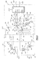
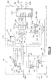
- la figure 2 est un schéma qui illustre le premier mode de réalisation d'un antivol électrique selon l'invention comportant une centrale d'antivol, sur lequel l'antivol électrique est représenté à l'état verrouillé en l'absence de clef ;
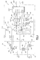
- la figure 3 est un schéma similaire à celui de la figure 2 sur lequel l'antivol électrique est illustré à l'état verrouillé et en présence de clef ;
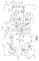
- la figure 4 est un schéma similaire à celui de la figure 3 sur lequel l'antivol électrique est illustré dans une phase de transition lorsqu'il passe de l'état verrouillé à l'état déverrouillé
- la figure 5 est un schéma similaire à celui de la figure 4 sur lequel l'antivol électrique est représenté à l'état déverrouillé ;
- la figure 6 est un schéma similaire à celui de la figure 5 sur lequel l'antivol électrique est illustré à l'état déverrouillé après retrait de la clef ;
- la figure 7 est un schéma similaire à celui de la figure 6 sur lequel l'antivol électrique est illustré dans une phase de transition lorsqu'il passe de l'état déverrouillé à l'état verrouillé
- la figure 8 est un schéma similaire à celui de la figure 2 qui illustre une variante de réalisation des moyens de détection de l'état de l'antivol ;
- les figures 9 à 14 sont des schémas similaires à ceux des figures 2 à 7 qui illustrent un second mode de réalisation d'un antivol électrique conforme aux enseignements de l'invention.
- FIG. 1 is a diagram illustrating a principle for producing an anti-theft device according to the prior art comprising an electronic anti-theft control unit;
- FIG. 2 is a diagram which illustrates the first embodiment of an electric anti-theft device according to the invention comprising an anti-theft control unit, on which the electric anti-theft device is shown in the locked state in the absence of a key;
- Figure 3 is a diagram similar to that of Figure 2 in which the electric lock is illustrated in the locked state and in the presence of a key;
- Figure 4 is a diagram similar to that of Figure 3 in which the electric lock is illustrated in a transition phase when it goes from the locked state to the unlocked state
- Figure 5 is a diagram similar to that of Figure 4 in which the electric lock is shown in the unlocked state;
- Figure 6 is a diagram similar to that of Figure 5 in which the electric lock is illustrated in the unlocked state after removal of the key;
- Figure 7 is a diagram similar to that of Figure 6 in which the electric lock is illustrated in a transition phase when it goes from the unlocked state to the locked state
- FIG. 8 is a diagram similar to that of FIG. 2 which illustrates an alternative embodiment of the means for detecting the state of the anti-theft device;
- Figures 9 to 14 are diagrams similar to those of Figures 2 to 7 which illustrate a second embodiment of an electric lock according to the teachings of the invention.
L'antivol électrique schématisé à la figure 1 comporte,
conformément aux enseignements de l'état de la technique,
une clef 10, ou une fausse clef, qui est destinée à venir
s'introduire dans le canon, ou dans un faux canon, d'un
commutateur d'antivol 12.The electric anti-theft system shown diagrammatically in FIG. 1 comprises,
in accordance with the teachings of the state of the art,
a key 10, or a false key, which is intended to come
get into the barrel, or into a fake cannon, of a
Le commutateur 12 est prévu pour équiper le tableau de
bord du véhicule et sa conception est du type sensiblement
proche de celle du commutateur de démarrage du véhicule
selon l'état de la technique.
L'utilisateur manoeuvre la clef de contact 10, ou un
anneau d'allumage simulant une telle manoeuvre. La clef de
contact 10 est en fait une fausse clef en ce qu'elle n'agit pas
nécessairement sur une serrure mécanique, bien qu'une telle
clef réelle apporte un degré supplémentaire de sécurité en
ajoutant un moyen de verrouillage ou de déverrouillage
supplémentaire en chaíne avec la conception générale d'un
antivol électrique.The user operates the
Le commutateur d'antivol 12 comporte un interrupteur de
clef 14 qui est destiné à détecter l'absence de la clef 10 ou la
présence en position introduite de cette dernière.The
Le commutateur 12 comporte également un interrupteur de
commande à positions multiples 16 pour la commande du
démarrage du moteur du véhicule et pour la commande de
l'alimentation de différents circuits électriques du véhicule, et
notamment du circuit d'allumage du moteur à combustion.The
L'interrupteur de clef 14 est relié par une ligne 18 à une
entrée d'une centrale d'antivol 20 tandis que l'interrupteur de
commande 16 est relié à une ligne 22 par une autre entrée de
la centrale d'antivol 20.The
La centrale d'antivol comporte un circuit d'analyse qui est
notamment capable de lire les positions qu'occupent les
interrupteurs 14 et 16 du commutateur 12. The anti-theft system has an analysis circuit which is
especially able to read the positions occupied by
La centrale d'antivol comporte par exemple un
microcontrôleur tel qu'un circuit INTEL 8051. Ce circuit
contient un programme de lectures des ports d'entrée pour
informer la centrale d'antivol des positions des différents
interrupteurs du commutateur 12 comme cela sera expliqué par
la suite.The anti-theft system includes for example a
microcontroller such as an INTEL 8051. circuit
contains a program for reading the input ports for
inform the central anti-theft system of the positions of the
Selon une conception connue, et par une autre entrée et
une ligne 23, la centrale d'antivol 20 peut échanger des
signaux avec une station d'interrogation et de réception 24 qui
échange, par des lignes 26 et 28 des signaux avec par
exemple un badge 30 d'accès sans clef au véhicule.According to a known conception, and by another entry and
En fonction des échanges avec la centrale d'antivol 20,
celle-ci produit sur une liaison 32 un signal de commande de la
mise en marche d'un moteur d'antivol 34 qui agit sur un organe
36 de blocage mécanique de la colonne de direction du
véhicule, ou de l'arbre de sortie de la boíte de vitesses.Depending on the exchanges with the central
Par ailleurs, si l'utilisateur oublie le badge radiofréquence
30 à l'intérieur du véhicule, ou s'il omet de manoeuvrer la clef
10 pour mettre en oeuvre une séquence de verrouillage de
l'antivol alors qu'il laisse son badge 30 dans le véhicule, la
centrale d'antivol 20 produit le déclenchement d'un moyen
d'alarme d'oubli 38.Furthermore, if the user forgets the
On décrira maintenant un premier mode de réalisation d'un antivol électrique selon l'invention en se reportant au schéma de la figure 2 sur laquelle des composants identiques ou similaires à ceux de la figure 1 sont désignés par les mêmes chiffres de référence.We will now describe a first embodiment an electric lock according to the invention with reference to diagram of Figure 2 in which identical components or similar to those in Figure 1 are designated by same reference figures.
L'interrupteur de clef 14 comporte un contact mobile
basculant 42 qui est relié en permanence à la borne -BAT de
la batterie du véhicule et dont l'extrémité libre coopère avec un
contact fixe 44 en l'absence de clef, ou avec un contact fixe 46
lorsqu'une clef 10 est introduite dans le commutateur de
commande 12 ou lorsqu'une telle introduction est simulée.The
L'interrupteur de clef 14 est associé en parallèle avec un
interrupteur de clef complémentaire 48 qui comporte un
contact mobile 50 qui se déplace simultanément avec le
contact mobile 42 de l'interrupteur de clef 14.The
Le contact mobile 50 est relié en permanence, par la ligne
18, au port d'entrée "DEMANDE" de la centrale d'antivol 20 de
manière que cette dernière puisse déclencher une séquence
d'identification de la demande de déverrouillage de l'antivol ou
de la demande de verrouillage de l'antivol.The
Le contact mobile 50 de l'interrupteur de clef
complémentaire 48 est susceptible de coopérer avec un
contact fixe 52 en présence de clef, comme cela est
notamment représenté sur la figure 3, de manière à relier
électriquement l'entrée "DEMANDE" de la centrale d'antivol 20
à la polarité -BAT de la batterie du véhicule.The
En l'absence de clef, le contact mobile 50 coopère avec
un contact fixe 54 qui est un contact neutre et le port d'entrée
"DEMANDE" n'est relié à aucune polarité de la batterie du
véhicule.In the absence of a key, the
L'interrupteur de commande à positions multiples 16 est
un interrupteur de type rotatif qui comporte un contact mobile
de commande 56 qui est relié en permanence à la borne +BAT
de la batterie du véhicule.The
Le contact mobile de commande 56 est susceptible
d'occuper successivement plusieurs positions décalées
angulairement les unes par rapport aux autres et qui sont
repérées "0", "ACC", "M" et "D" sur les figures.The
Dans ces positions successives d'arrêt, d'alimentation
d'accessoires électriques du véhicule, de marche, et de
démarrage du moteur du véhicule, le contact mobile rotatif de
commande 56 est susceptible de coopérer avec une ou
plusieurs pistes conductrices agencées en arc de cercle
constituant les contacts fixes de l'interrupteur 16.In these successive stop, feed positions
vehicle electrical accessories, walking, and
vehicle engine start, the rotary mobile contact of
Lorsque le contact mobile 56 est dans la position ACC, il
coopère avec une piste fixe 58 qui est reliée électriquement au
circuit d'alimentation +ACC des accessoires du véhicule.When the
Lorsque le contact mobile de commande 56 est dans la
position M, il est simultanément en contact avec la piste 58 et
avec une piste conductrice 60 qui est reliée au circuit
d'allumage +ALL du moteur du véhicule avec interposition d'un
dispositif d'inhibition 64.When the
Lorsque le contact mobile de commande 56 est dans la
position "D", il est simultanément en contact avec la piste 60
ainsi qu'avec une piste conductrice 62 qui est reliée au circuit
+DEM d'alimentation électrique du démarreur du moteur à
combustion du véhicule.When the
On décrira maintenant plus en détail le module de blocage 66 entouré par une ligne en trait pointillé à la partie droite de la figure 2.The blocking module will now be described in more detail. 66 surrounded by a dotted line on the right of Figure 2.
Le moteur 34 de l'antivol motorisé est un moteur électrique
dont les bornes opposées A1 et A2 sont reliées à un bloc
68 d'alimentation électrique du moteur 34.The motorized
Une première borne B1 du bloc d'alimentation est reliée
en permanence à la borne +BAT de la batterie du véhicule
tandis que sa seconde borne B2 est reliée en permanence à
une entrée V/D de la centrale d'antivol 20 qui est une entrée
de détection de changement d'état de cette seconde borne B2.A first terminal B1 of the power supply unit is connected
permanently at the + BAT terminal of the vehicle battery
while its second terminal B2 is permanently connected to
a V / D input of the central
Comme cela sera expliqué par la suite, la seconde borne
B2 du bloc d'alimentation 68 est également reliée à la borne -
BAT de la batterie du véhicule par l'intermédiaire de
l'interrupteur de clef 14 et d'interrupteurs d'alimentation 70. As will be explained later, the second terminal
B2 of
Le bloc 68 d'alimentation reçoit des ordres de commande
de l'alimentation du moteur 34, en vue de provoquer son
déverrouillage ou son verrouillage par des lignes 72D et 72V
reliées à des ports de sortie DEV et VER de la centrale
d'antivol 20.
En fonction de l'alimentation du bloc 68 et des ordres
délivrés par la centrale d'antivol 20, le moteur 34 est
susceptible de tourner dans l'un ou l'autre sens entre une
position de verrouillage de l'antivol qui est déterminée par une
butée mécanique de verrouillage 74 avec laquelle est
susceptible de coopérer un organe mécanique de butée 76 lié
en rotation à l'arbre de sortie du moteur 34, et une position
angulaire de déverrouillage de l'antivol déterminée par une
butée mécanique de déverrouillage 78.Depending on the power supply of
On décrira maintenant les deux interrupteurs
d'alimentation de la seconde borne B2 du bloc d'alimentation
68.We will now describe the two switches
supply of the second terminal B2 of the
Ces interrupteurs sont constitués par un contact mobile
rotatif commun 80 qui est lié en rotation à l'arbre de sortie du
moteur 34, par une liaison mécanique illustrée par la ligne en
trait pointillé 82.These switches consist of a movable contact
Pour constituer le premier interrupteur d'alimentation au
sens de l'invention, le contact mobile rotatif 80 est susceptible
de coopérer ou non avec un premier contact fixe 84 réalisé
sous la forme d'une piste conductrice qui est reliée au premier
contact fixe 44 de l'interrupteur de clef 14 par une ligne 85.To constitute the first power switch at
sense of the invention, the rotary
Le premier interrupteur d'alimentation 80, 84 est ouvert
lorsque l'antivol est en position verrouillée et il est fermé pour
toutes les autres positions de l'antivol.The
Le second interrupteur d'alimentation de la borne B2 est
constitué par le contact rotatif 80 qui est susceptible de
coopérer avec un second contact fixe 86 réalisé sous la forme
d'une piste conductrice reliée en permanence au second
contact fixe 46 de l'interrupteur de clef 14 par une ligne 87.The second power switch of terminal B2 is
constituted by the
Le second interrupteur d'alimentation 80, 86 n'est ouvert
que lorsque l'antivol est en position déverrouillée et il est
fermé pour toutes les autres positions de l'antivol.The
La centrale d'antivol 20 comporte également un port
d'entrée M1V de détection de l'état verrouillé de l'antivol et un
port d'entrée M2D de détection de l'état déverrouillé de
l'antivol.The
Les ports d'entrée M1V et M2D sont reliés à des moyens 88 de détection de l'état de l'antivol.M1V and M2D input ports are connected to means 88 for detecting the status of the lock.
Dans ce premier mode de réalisation, les moyens 88 de
détection de l'état de l'antivol comportent un interrupteur 90 de
détection du verrouillage de l'antivol comportant un contact
mobile 92 qui est relié en permanence à la borne -BAT de la
batterie du véhicule et qui, lorsque l'antivol est en position
verrouillée, coopère avec un contact fixe 94 qui est relié en
permanence à l'entrée M1V de la centrale d'antivol 20.In this first embodiment, the
Lorsque l'antivol n'est pas en position verrouillée, le
contact mobile 92 de l'interrupteur 90 de détection du
verrouillage de l'antivol coopère avec un contact fixe neutre
96.When the lock is not in the locked position, the
Les moyens 88 de détection de l'état de l'antivol
comportent également un interrupteur 98 de détection du
déverrouillage de l'antivol qui comporte un contact mobile 100
qui est relié en permanence à la borne -BAT de la batterie du
véhicule et qui coopère avec un contact fixe neutre 102
lorsque l'antivol n'est pas en position déverrouillée et qui
coopère avec un contact fixe 104 qui est relié en permanence
à l'entrée M2D de la centrale d'antivol 20, lorsque l'antivol est
en position déverrouillée. The means 88 for detecting the state of the anti-theft device
also include a
Enfin, la centrale d'antivol est reliée par une liaison codée
106 aux autres composants de l'antivol électrique et par une
liaison 108 à des moyens de diagnostic.Finally, the anti-theft control unit is connected by a
Le dispositif d'inhibition 64 est, dans ce premier mode de
réalisation, constitué par un interrupteur rotatif qui comporte
un contact mobile rotatif d'inhibition 110 qui est relié en
permanence à la piste conductrice 60 de l'interrupteur de
commande à positions multiples 16 et qui, uniquement en
position déverrouillée de l'antivol, est susceptible de coopérer
avec un plot fixe 112 relié au circuit électrique +ALL
d'alimentation du circuit d'allumage du moteur du véhicule.The
A cet effet, le contact mobile rotatif d'inhibition 110 est
relié à l'arbre de sortie du moteur 34 par une liaison
mécanique représentée par la ligne en trait pointillé 114 de la
figure 2.For this purpose, the movable
On décrira maintenant le fonctionnement de l'antivol électrique illustré aux figures 2 à 7.We will now describe the operation of the anti-theft device electric illustrated in figures 2 to 7.
Dans la position verrouillée illustrée sur la figure 2, et en
l'absence de clef, le moteur 34 est en contact avec la butée
mécanique de verrouillage 74, le contact mobile 42 de l'interrupteur
de clef 14 est en contact avec le contact fixe 44 et le
contact mobile de commande 56 est dans sa position d'arrêt
"O".In the locked position illustrated in Figure 2, and in
the absence of a key, the
Le premier interrupteur d'alimentation 80, 84 est ouvert
tandis que le second interrupteur d'alimentation 80, 86 est
fermé.The
En conséquence, la seconde borne B2 du bloc 68
d'alimentation du moteur électrique 34 n'est pas reliée à la
borne -BAT de la batterie du véhicule.Consequently, the second terminal B2 of
Lorsque le conducteur introduit la clef 10 dans le
commutateur 12, ou lorsqu'il simule une telle introduction, il
provoque d'abord le changement d'état de l'interrupteur de clef
14 qui passe de la position illustrée sur la figure 2 à la position
illustrée sur la figure 3.When the driver inserts the key 10 into the
Dans cette nouvelle position, le contact mobile 42 est en
contact avec le contact 46 et il établit ainsi une liaison
électrique entre la seconde borne B2 du bloc d'alimentation 68
et la borne -BAT de la batterie du véhicule par la ligne 87 et
par le second interrupteur d'alimentation 80, 86 qui est fermé.In this new position, the
Simultanément avec le changement de position de
l'interrupteur de clef 14, l'interrupteur complémentaire 48 a
changé de position et son contact mobile 50 a établi la liaison
électrique entre le port d'entrée DEMANDE de la centrale
d'antivol 20 et la borne -BAT de la batterie du véhicule.Simultaneously with the change of position of
the
En conséquence, ce port d'entrée a reçu un ordre qui est
analysé par la centrale d'antivol 20 comme un ordre de
commande du déverrouillage de l'antivol.As a result, this port of entry has received an order which is
analyzed by the central
Après avoir analysé cet ordre, la centrale d'antivol 20
transmet au bloc d'alimentation 68, par la ligne 72D, un ordre
de commande du début du déverrouillage qui provoque la mise
en rotation, dans le sens horaire en considérant la figure 3, du
moteur 34.After analyzing this order, the central
L'action du conducteur sur l'interrupteur de commande à
positions multiples 16, quelle que soit la position qu'il choisit
pour cet interrupteur, ne peut pas provoquer le démarrage du
moteur, avant que l'antivol soit en position déverrouillée, car le
circuit d'allumage du moteur du véhicule n'est pas alimenté,
l'interrupteur d'inhibition 64 étant ouvert.Driver's action on the control switch at
Dans la position de transition, illustrée sur la figure 4,
entre l'état verrouillé et l'état déverrouillé de l'antivol, on
constate que les deux interrupteurs d'alimentation 80, 84 et
80, 86 sont fermés et que l'interrupteur 90 de détection du
verrouillage de l'antivol a changé de position en transmettant
un signal correspondant au port d'entrée M1V de la centrale
d'antivol 20.In the transition position, illustrated in Figure 4,
between the locked state and the unlocked state of the anti-theft device,
notes that the two
L'interrupteur d'inhibition 64 est toujours ouvert et il n'est
pas possible de provoquer le démarrage du moteur du
véhicule.
La rotation du moteur 34 se poursuit jusqu'à la position de
déverrouillage de l'antivol qui est illustré sur la figure 5.The rotation of the
Lorsque cette position est atteinte, le second interrupteur
d'alimentation 80, 86 s'ouvre et la seconde borne B2 du bloc
d'alimentation 68 n'est plus reliée à la borne -BAT de la
batterie du véhicule, provoquant ainsi l'arrêt du moteur 34 en
position déverrouillée de l'antivol.When this position is reached, the
Lorsque cette position déverrouillée est atteinte,
l'interrupteur 98 de détection du déverrouillage de l'antivol
change de position et il transmet un signal correspondant au
port d'entrée M2D de la centrale d'antivol qui est relié à la
borne -BAT de la batterie du véhicule.When this unlocked position is reached,
the anti-theft unlocking
Dans cette position déverrouillée, l'interrupteur d'inhibition
64 est fermé et le circuit d'allumage du moteur du véhicule est
alimenté car il est relié à la borne +BAT de la batterie par le
contact mobile de commande 56 lorsque celui-ci est en regard
de la piste conductrice 60.In this unlocked position, the muting
Le conducteur peut donc alors provoquer le démarrage du moteur et continuer l'utilisation de celui-ci.The driver can therefore cause the starting of the engine and continue using it.
Lorsque le conducteur arrête son véhicule, il arrête le moteur et provoque le verrouillage de l'antivol en retirant la clef.When the driver stops his vehicle, he stops the engine and causes the lock to lock by removing the key.
En effet, lorsqu'il retire la clef, et comme cela est illustré
sur la figure 6, il provoque un changement d'état simultané de
l'interrupteur de clef 14 et de l'interrupteur complémentaire 48.Indeed, when he withdraws the key, and as illustrated
in FIG. 6, it causes a simultaneous change of state of
the
Le changement de position du contact mobile 50 de
l'interrupteur complémentaire 48 provoque à nouveau un
changement d'état à l'entrée DEMANDE de la centrale d'antivol
qui analyse de changement d'état comme une demande du
verrouillage de l'antivol et la centrale d'antivol 20 transmet
alors un ordre de commande correspondant de verrouillage par
la ligne 72V au bloc d'alimentation 68.The change in position of the
La seconde borne B2 du bloc d'alimentation 68 est reliée
à la borne -BAT de la batterie du véhicule par le premier
interrupteur d'alimentation 80, 84 qui est fermé, par la ligne 85
et par le contact mobile basculant 42 de l'interrupteur de clef
14.The second terminal B2 of the
De ce fait, l'ordre de commande du verrouillage transmis
au bloc d'alimentation 68 par la ligne 72V peut être exécuté et
la rotation, en sens anti-horaire en considérant la figure 6, du
moteur 34 peut commencer.As a result, the locking control command transmitted
to
Lorsque la rotation en vue du verrouillage a commencé, et comme cela est illustré sur la figure 7, l'interrupteur d'inhibition 64 est immédiatement ouvert, et il est alors impossible au conducteur de provoquer à nouveau un démarrage du moteur du véhicule tant que l'état déverrouillé n'a pas été atteint.When the rotation for locking has started, and as illustrated in figure 7, the switch muting 64 is immediately opened, and it is then impossible for the driver to provoke a starting the vehicle engine as long as the unlocked state has not been reached.
Dans la position de transition illustrée sur la figure 7, les
deux interrupteurs d'alimentation 80, 84 et 80, 86 sont fermés
et l'interrupteur 98 de détection du déverrouillage de l'antivol a
changé de position, transmettant une information
correspondante à l'entrée M2D de la centrale d'antivol 20.In the transition position illustrated in Figure 7, the
two
La rotation du moteur 34 s'effectue dans le sens anti-horaire
et se poursuit jusqu'à ce qu'il vienne à nouveau
occuper sa position angulaire de verrouillage illustrée sur la
figure 2.The
Lorsque cette position de verrouillage est à nouveau
atteinte, l'interrupteur 90 de détection du verrouillage a
nouveau changé de position en transmettant l'information
correspondante à l'entrée M1V de la centrale d'antivol 20,
toute nouvelle demande adressée à la centrale d'antivol 20 à
son port d'entrée DEMANDE étant ainsi ultérieurement
analysée comme un ordre de demande de déverrouillage de
l'antivol.When this locking position is again
reached, the
La variante de réalisation illustrée sur la figure 8 diffère
du premier mode de réalisation illustré aux figures 2 à 7
seulement en ce que le contact mobile 92 de l'interrupteur 90
de détection du verrouillage de l'antivol n'est pas relié directement
à la borne -BAT de la batterie, car il est relié directement
au premier contact fixe 44 de l'interrupteur de clef 14.The variant embodiment illustrated in FIG. 8 differs
of the first embodiment illustrated in Figures 2 to 7
only in that the
De même, le contact mobile 100 de l'interrupteur 98 de
détection du déverrouillage de l'antivol est relié directement au
second contact fixe 46 de l'interrupteur de clef 14.Similarly, the
Le fonctionnement de la variante illustrée à la figure 8 est en tous points identique à celui qui a été décrit en référence aux figures 2 à 7.The operation of the variant illustrated in FIG. 8 is identical in all respects to that described with reference in Figures 2 to 7.
On décrira maintenant le second mode de réalisation illustré aux figures 9 à 14.The second embodiment will now be described. illustrated in figures 9 to 14.
Ce second mode de réalisation diffère du premier mode de réalisation illustré aux figures 2 à 7 d'abord de par la structure des moyens d'inhibition.This second embodiment differs from the first embodiment embodiment illustrated in Figures 2 to 7 first of all by the structure means of inhibition.
En effet, dans ce second mode de réalisation, le contact
mobile rotatif de commande 56 est relié par une ligne 116 au
plot fixe 112 de l'interrupteur d'inhibition 64 dont le contact
mobile rotatif d'inhibition 110 est relié au permanence au pôle
+BAT de la batterie.Indeed, in this second embodiment, the contact
rotary control mobile 56 is connected by a
En conséquence, les circuits +DEM, +ALL et +ACC du
véhicule ne peuvent être alimentés électriquement, par la
coopération du contact mobile de commande 56 avec la piste
correspondante 62, 60 ou 58, que lorsque l'interrupteur
d'inhibition 64 est fermé, c'est-à-dire lorsque l'antivol est
déverrouillé.Consequently, the circuits + DEM, + ALL and + ACC of the
vehicle cannot be powered electrically, by the
cooperation of the
Le second mode de réalisation illustré aux figures 9 à 14 diffère aussi du premier mode de réalisation par la structure des interrupteurs d'alimentation et des interrupteurs de détection du verrouillage et du déverrouillage de l'antivol qui sont ici communs.The second embodiment illustrated in Figures 9 to 14 also differs from the first embodiment by the structure power switches and power switches detection of the locking and unlocking of the anti-theft device which are common here.
En effet, comme on peut le voir notamment sur la figure 9,
le premier interrupteur d'alimentation est constitué par un
contact mobile 80-92 qui est susceptible de coopérer avec un
contact fixe 84 relié à la borne B2 du bloc d'alimentation 68 ou
avec un contact fixe 94 relié à l'entrée M1V de la centrale
d'antivol 20 pour constituer alors un interrupteur 90 de
détection du verrouillage de l'antivol.Indeed, as we can see in particular in Figure 9,
the first power switch consists of a
mobile contact 80-92 which is likely to cooperate with a
fixed
De la même manière, le second interrupteur d'alimentation
est constitué par un contact mobile 80-100 qui est susceptible
de coopérer avec un contact 86 relié à la borne B2 du bloc
d'alimentation 68 ou avec un contact fixe 104 relié à l'entrée
M2D de la centrale d'antivol 20.Likewise, the second power switch
consists of a mobile contact 80-100 which is susceptible
to cooperate with a
Le fonctionnement du second mode de réalisation de l'antivol électrique illustré aux figures 9 à 14 est en tous points identique à celui décrit en référence aux figures 2 à 8.The operation of the second embodiment of the electric lock shown in Figures 9 to 14 is fully identical to that described with reference to FIGS. 2 to 8.
Claims (13)
- An anti-theft device, especially for a motor vehicle, of the type comprising:and of the type in which the anti-theft switch (12) comprises:an anti-theft switch (12) for supplying power to various electrical circuits of the vehicle (+DEM, +ALL) ;a motorised anti-theft unit, including an electric motor (34) for driving a stop member (36) between a locked position and an unlocked position;and a central control circuit (20) connected to the foregoing elements for performing a method of controlling the anti-theft device;characterised in that at least one of the electrical circuits (+ALL, +DEM) of the vehicle is connected to a polarity (+BAT) of the power source through the multi-position control interruptor (16) and through an inhibiting device (64) which establishes the electrical power supply of the said circuit (+ALL) only when the anti-theft unit is in its unlocked position;a key interruptor (14, 48) for detecting simulated introduction of a key (10) into the anti-theft switch (12) ;and a multi-position control interruptor (16) for controlling the supply of power sequentially to the said electrical circuits of the vehicle (+ALL, +DEM), and including a moving control contact (56) connected to one polarity (+BAT) of a power source, and a set of fixed contacts (58, 60, 62) with which the moving control contact enters into contact successively during operation of the switch (12), whereby to cause the engine of the vehicle to start,
and in that the key interruptor (14) has a moving contact (42) which is connected to the power source (+BAT) and which is arranged to:cooperate with a first fixed contact (44) connected to the drive motor (34) of the motorised anti-theft unit in the absence of a key, and through a first power interruptor (80, 84) which is open when the anti-theft unit is in its locked position;or to cooperate with a second fixed contact (46) connected to the drive motor (34) of the motorised anti-theft unit in the presence of a key and through a second power interruptor (80, 86) which is open when the anti-theft unit is in its unlocked position;and in that the central control circuit (20) has an input (DEMAND) for detecting a change in position of the moving contact (42, 50) of the key interruptor (14, 48);and in that the central control circuit (20) has an input (M1V) for detecting the locked state of the anti-theft unit and an input (M2D) for detecting the unlocked state of the anti-theft unit, which are connected to means (88) for detecting the state of the anti-theft unit. - An electrical anti-theft device according to Claim 1, characterised in that the inhibiting device is an inhibiting interruptor (64) having a moving contact (110) which is connected to the said fixed contact (60) of the multi-position control interruptor (16), and which co-operates with a fixed contact pad (112), connected to the said electrical circuit (+ALL) when the anti-theft unit is in its unlocked position.
- An electrical anti-theft device according to Claim 1, characterised in that the moving control contact (56) of the multi-position control interruptor (16) of the anti-theft switch (12) is connected to a polarity (+BAT) of the power source through an inhibiting device (64) which establishes the electrical connection only when the anti-theft unit is in its unlocked position.
- An electrical anti-theft device according to Claim 3, characterised in that the inhibiting device is an inhibiting interruptor (64), the moving contact (110) of which is connected to one polarity (+BAT) of the power source and co-operates with a fixed contact pad (112) connected to the moving control contact (56) when the anti-theft unit is in its unlocked position.
- An electrical anti-theft device according to Claim 2 or Claim 4, characterised in that the moving contact (110) of the inhibiting interruptor (64) is coupled in rotation to the motor of the motorised anti-theft unit.
- An electrical anti-theft device according to any one of the preceding Claims, characterised in that:the first power interruptor comprises a moving contact (80) which is permanently connected to the motor (34) and which is adapted to cooperate with a first fixed contact pad (84) connected to the first fixed contact (44) of the key interruptor (14) when the first power interruptor (80, 84) is in its closed position;and the second power interruptor comprises a moving contact (80) which is permanently connected to the motor (34) and which is adapted to cooperate with a second fixed contact pad (86) connected to the second fixed contact (46) of the key interruptor (14) when the second power interruptor (80, 86) is in its closed position.
- An electrical anti-theft device according to Claim 6, characterised in that the said first and second fixed contact pads (84, 86) are staggered conductive tracks, and the said moving contact (80) is a moving contact (80) which is common to the first and second power interruptors (80, 84, 86) and which is coupled in rotation to the electric motor (34).
- An electrical anti-theft device according to any one of the preceding Claims, characterised in that the input (DEMAND) of the central control circuit (20) for detecting a change in position of the moving contact (42) of the key interruptor (14) is connected to one polarity (-BAT) of the power source through an interruptor (48) having a moving contact (50) which is displaced simultaneously with the moving contact (42) of the key interruptor (14), and which is closed (48) in the absence of a key.
- An electrical anti-theft device according to any one of the preceding Claims, characterised in that the means (88) for detecting the state of the anti-theft unit comprise:an interruptor (90) for detecting locking of the anti-theft unit and comprising a moving contact (92) which is connected to one polarity (-BAT) of the power source and which is adapted to cooperate with a fixed contact (94) connected to the input for detection of the locked state of the anti-theft unit (M1V), when the anti-theft unit is in its locked position;and an interruptor (98) for detecting unlocking of the anti-theft unit and having a moving contact (100) which is connected to one polarity (-BAT) of the power source and which is adapted to cooperate with a fixed contact (104) connected to the input for detecting the unlocked state of the anti-theft unit (M2D), when the anti-theft unit is in its unlocked position.
- An electrical anti-theft device according to Claim 9, characterised in that the moving contact (92) of the interruptor (90) for detecting unlocking of the anti-theft unit is connected to the said first fixed contact (44) of the key interruptor (14), and in that the moving contact (100) of the interruptor (98) for detecting unlocking of the anti-theft unit is connected to the second fixed contact (46) of the key interruptor (14).
- An electrical anti-theft device according to Claim 9, characterised in that the moving contact (92) of the interruptor (90) for detecting locking of the anti-theft unit consists of the moving contact (80) of the first power interruptor (80, 84), arranged to cooperate with a fixed contact (96) which is connected to the input for detecting the locked state of the anti-theft unit (M1V), when the first power interruptor (80, 84) is open, and the moving contact (100) of the interruptor (98) for detecting unlocking of the anti-theft unit consists of the moving contact (80) of the second power interruptor (80, 86), arranged to cooperate with a fixed contact (104) which is connected to the input for detecting the unlocked state of the anti-theft unit (M2D), when the second power interruptor (80, 86) is open.
- An electrical anti-theft device according to any one of the preceding Claims, characterised in that it includes an electrical power pack (68) for the motor (34), which receives commands from the central control circuit (20) for locking (72V) or unlocking (72D) of the anti-theft unit, in that a first terminal (B1) of the power pack (68) is permanently connected to a first polarity (+BAT) of the power source, and the second terminal (B2) of the power pack (68) is arranged to be connected to the second polarity (-BAT) of the power source through the key interruptor (14) and either the first power interruptor (80, 84) or the second power interruptor (80, 86).
- An electrical anti-theft device according to any one of the preceding Claims, characterised in that the anti-theft switch (12) is a rotary switch.
Applications Claiming Priority (3)
| Application Number | Priority Date | Filing Date | Title |
|---|---|---|---|
| FR9503392A FR2731965B1 (en) | 1995-03-21 | 1995-03-21 | ELECTRICAL THEFT |
| FR9503392 | 1995-03-21 | ||
| US08/622,032 US5654689A (en) | 1995-03-21 | 1996-03-26 | Electric anti-theft security system |
Publications (2)
| Publication Number | Publication Date |
|---|---|
| EP0733521A1 EP0733521A1 (en) | 1996-09-25 |
| EP0733521B1 true EP0733521B1 (en) | 2001-07-18 |
Family
ID=26231830
Family Applications (1)
| Application Number | Title | Priority Date | Filing Date |
|---|---|---|---|
| EP96400553A Expired - Lifetime EP0733521B1 (en) | 1995-03-21 | 1996-03-18 | Electric anti-theft device |
Country Status (5)
| Country | Link |
|---|---|
| US (1) | US5654689A (en) |
| EP (1) | EP0733521B1 (en) |
| DE (1) | DE69613877T2 (en) |
| ES (1) | ES2160781T3 (en) |
| FR (1) | FR2731965B1 (en) |
Families Citing this family (30)
| Publication number | Priority date | Publication date | Assignee | Title |
|---|---|---|---|---|
| FR2731968B1 (en) * | 1995-03-21 | 1997-04-30 | Valeo Securite Habitacle | ELECTRICAL THEFT, ESPECIALLY FOR A MOTOR VEHICLE |
| US6829476B1 (en) * | 1997-01-24 | 2004-12-07 | Lawrence J. Gelbein | Pager-based gas valve controller |
| US6034442A (en) * | 1997-02-18 | 2000-03-07 | Mostrom; Lloyd C. | Frustrator--Model E |
| DE10039090A1 (en) | 2000-08-10 | 2002-02-21 | Daimler Chrysler Ag | Electronic starter and steering lock device for a motor vehicle |
| US6516640B2 (en) | 2000-12-05 | 2003-02-11 | Strattec Security Corporation | Steering column lock apparatus and method |
| US6571587B2 (en) | 2001-01-09 | 2003-06-03 | Strattec Security Corporation | Steering column lock apparatus and method |
| US6420967B1 (en) | 2001-01-31 | 2002-07-16 | Lear Corporation | System and method for shared vehicle tire pressure monitoring, remote keyless entry, and vehicle immobilization |
| JP3851803B2 (en) * | 2001-02-09 | 2006-11-29 | 株式会社東海理化電機製作所 | Electronic vehicle anti-theft device |
| JP3851802B2 (en) * | 2001-02-09 | 2006-11-29 | 株式会社東海理化電機製作所 | Electronic vehicle anti-theft device |
| ES2185489B1 (en) * | 2001-06-18 | 2004-01-16 | Valeo Sist Seguridad Y Cierre | LOW CURRENT START SWITCH FOR VEHICLES, AND STARTING EQUIPMENT EQUIPPED WITH SUCH SWITCH. |
| JP4658406B2 (en) | 2001-08-24 | 2011-03-23 | 株式会社東海理化電機製作所 | Electronic vehicle anti-theft device |
| US6864803B2 (en) | 2001-10-12 | 2005-03-08 | Lear Corporation | System and method for tire pressure monitoring using CDMA tire pressure signals |
| US6693522B2 (en) | 2001-10-12 | 2004-02-17 | Lear Corporation | System and method for tire pressure monitoring including automatic tire location recognition |
| US6933898B2 (en) * | 2002-03-01 | 2005-08-23 | Lear Corporation | Antenna for tire pressure monitoring wheel electronic device |
| US6829924B2 (en) * | 2002-03-01 | 2004-12-14 | Lear Corporation | Tire pressure monitoring system with low frequency initiation approach |
| US20030164759A1 (en) * | 2002-03-01 | 2003-09-04 | Lear Corporation | System and method for tire pressure monitoring with optimal tire pressure indication during tire pressure adjustment |
| US20030164760A1 (en) * | 2002-03-01 | 2003-09-04 | Lear Corporation | System and method for tire pressure monitoring using vehicle radio |
| US7154414B2 (en) * | 2002-03-01 | 2006-12-26 | Lear Corporation | System and method for remote tire pressure monitoring |
| US6647773B2 (en) | 2002-03-01 | 2003-11-18 | Lear Corporation | System and method for integrated tire pressure monitoring and passive entry |
| US6691567B2 (en) | 2002-03-01 | 2004-02-17 | Lear Corporation | System and method for tire pressure monitoring including automatic tire location recognition |
| US6725712B1 (en) | 2002-03-01 | 2004-04-27 | Lear Corporation | System and method for tire pressure monitoring with automatic tire location recognition |
| US6876265B2 (en) | 2002-03-01 | 2005-04-05 | Lear Corporation | System and method for using a saw based RF transmitter for AM modulated transmission in a TPM |
| US6788193B2 (en) | 2002-03-01 | 2004-09-07 | Lear Corporation | System and method for tire pressure monitoring providing automatic tire location recognition |
| US20030164034A1 (en) * | 2002-03-01 | 2003-09-04 | Lear Corporation | System and method for using a saw based RF transmitter for FM transmission in a TPM |
| US6668636B2 (en) | 2002-03-01 | 2003-12-30 | Lear Corporation | System and method for tire pressure monitoring including tire location recognition |
| US20030179086A1 (en) * | 2002-03-25 | 2003-09-25 | Lear Corporation | System for remote tire pressure monitoring with low frequency initiation antenna |
| US6838985B2 (en) * | 2002-03-25 | 2005-01-04 | Lear Corporation | System and method for remote tire pressure monitoring with low frequency initiation |
| FR2843932B1 (en) * | 2002-09-04 | 2004-11-19 | Renault Sa | IN A VEHICLE, CONTROL CIRCUIT FOR A SECURITY DEVICE. |
| US7140213B2 (en) * | 2004-02-21 | 2006-11-28 | Strattec Security Corporation | Steering column lock apparatus and method |
| JP2008284978A (en) * | 2007-05-17 | 2008-11-27 | Omron Corp | Engine starting device |
Family Cites Families (9)
| Publication number | Priority date | Publication date | Assignee | Title |
|---|---|---|---|---|
| US1798917A (en) * | 1929-03-20 | 1931-03-31 | Gen Motors Res Corp | Coincidental lock |
| US3735833A (en) * | 1971-10-12 | 1973-05-29 | J Meple Height Sutkowski | Theft prevention device for motor vehicles |
| JPS54158532A (en) * | 1978-06-02 | 1979-12-14 | Nippon Denso Co Ltd | Burglarproof method and device for car |
| FR2454503A1 (en) * | 1979-04-18 | 1980-11-14 | Renault | Electronic antitheft interlock esp. for vehicle - uses coded signals and is in two parts with one remote from keyed switch |
| GB8819003D0 (en) * | 1988-04-14 | 1988-09-14 | Liftsonic Ltd | Electrical apparatus |
| US5181592A (en) * | 1990-06-11 | 1993-01-26 | Sparton Corporation | Shift lever interlock system |
| JP2783908B2 (en) * | 1990-10-26 | 1998-08-06 | 自動車電機工業株式会社 | Electric seat device |
| US5451925A (en) * | 1992-04-09 | 1995-09-19 | Le; Hy D. | Passive instant automatic vehicle anti-theft device |
| FR2710599B1 (en) * | 1993-09-30 | 1995-11-24 | Valeo Securite Habitacle | Method for controlling a vehicle anti-theft device with remote control access system, and anti-theft device thus formed. |
-
1995
- 1995-03-21 FR FR9503392A patent/FR2731965B1/en not_active Expired - Fee Related
-
1996
- 1996-03-18 EP EP96400553A patent/EP0733521B1/en not_active Expired - Lifetime
- 1996-03-18 ES ES96400553T patent/ES2160781T3/en not_active Expired - Lifetime
- 1996-03-18 DE DE69613877T patent/DE69613877T2/en not_active Expired - Lifetime
- 1996-03-26 US US08/622,032 patent/US5654689A/en not_active Expired - Lifetime
Also Published As
| Publication number | Publication date |
|---|---|
| DE69613877D1 (en) | 2001-08-23 |
| EP0733521A1 (en) | 1996-09-25 |
| FR2731965A1 (en) | 1996-09-27 |
| DE69613877T2 (en) | 2002-04-11 |
| US5654689A (en) | 1997-08-05 |
| FR2731965B1 (en) | 1997-04-25 |
| ES2160781T3 (en) | 2001-11-16 |
Similar Documents
| Publication | Publication Date | Title |
|---|---|---|
| EP0733521B1 (en) | Electric anti-theft device | |
| FR2589930A1 (en) | CAR LOCKING SYSTEM CONTROLLED BY RADIO SIGNAL | |
| FR2461798A1 (en) | ANTI-THEFT DEVICE, IN PARTICULAR FOR AUTOMOTIVE VEHICLES | |
| FR2837766A1 (en) | Control system for starting vehicle engine includes transceiver carried by driver and detected by control system, enabling single switch starting | |
| FR2738585A1 (en) | METHOD FOR OPERATING A MOTOR VEHICLE CLOSURE WITH A FIXED STOP ELEMENT FOR AN OUTPUT ELEMENT | |
| EP1335330A2 (en) | System for unlocking a motor vehicle opening | |
| EP0733524B1 (en) | Electric anti-theft device, especially for a motor vehicle | |
| EP0761515B1 (en) | Electrical anti-theft system for a motor vehicle | |
| EP0733526B1 (en) | Improved electric anti-theft device, especially for a motor vehicle | |
| EP0733522B1 (en) | Electric anti-theft device for a motor vehicle | |
| EP0733523B1 (en) | Electric anti-theft device, especially for a motor vehicle | |
| EP0733525B1 (en) | Improved electric anti-theft device, especially for a motor vehicle | |
| EP2547554B1 (en) | Switching device for steering column of a vehicle | |
| EP0646506B1 (en) | Anti-theft control procedure and device therefor, for vehicles with remote control access systems | |
| FR2695604A1 (en) | Anti-theft device for vehicle having steering mechanism controlled by rotating shaft - has signal-sensitive electronic memory and electric motor controlling pin-type clutch mechanism | |
| EP2850598A1 (en) | Remote control for activating the functionalities of a motor vehicle using radiofrequency signals emitted by the remote control, remote control system including a central unit and a remote control, and method for activating the functionalities of a motor vehicle using a remote control system | |
| EP1046557B1 (en) | Access authorization system for a vehicle | |
| EP0921306B1 (en) | Control device for an automotive vehicle starter | |
| EP0596762B1 (en) | Theft preventing device on the steering mechanism for vehicle and key for such device | |
| FR2764927A1 (en) | Device for locking and unlocking vehicle doors from distance | |
| FR2873144A1 (en) | Electromechanical lock system for motor vehicle door, has two locks disposed in vehicle doors, where each lock has one locking switch that is switched from one state to another state by action of locking lever | |
| WO2001008943A1 (en) | Anti-theft device for vehicles | |
| FR2580056A1 (en) | Press safety circuit | |
| EP0419347A1 (en) | Protection system, especially for motor vehicles, of type comprising an apparatus such as an electronic control device of an alarm arragement |
Legal Events
| Date | Code | Title | Description |
|---|---|---|---|
| PUAI | Public reference made under article 153(3) epc to a published international application that has entered the european phase |
Free format text: ORIGINAL CODE: 0009012 |
|
| AK | Designated contracting states |
Kind code of ref document: A1 Designated state(s): DE ES GB IT |
|
| 17P | Request for examination filed |
Effective date: 19970321 |
|
| 17Q | First examination report despatched |
Effective date: 19991124 |
|
| GRAG | Despatch of communication of intention to grant |
Free format text: ORIGINAL CODE: EPIDOS AGRA |
|
| GRAG | Despatch of communication of intention to grant |
Free format text: ORIGINAL CODE: EPIDOS AGRA |
|
| GRAH | Despatch of communication of intention to grant a patent |
Free format text: ORIGINAL CODE: EPIDOS IGRA |
|
| GRAH | Despatch of communication of intention to grant a patent |
Free format text: ORIGINAL CODE: EPIDOS IGRA |
|
| RAP1 | Party data changed (applicant data changed or rights of an application transferred) |
Owner name: VALEO SECURITE HABITACLE |
|
| GRAA | (expected) grant |
Free format text: ORIGINAL CODE: 0009210 |
|
| AK | Designated contracting states |
Kind code of ref document: B1 Designated state(s): DE ES GB IT |
|
| GBT | Gb: translation of ep patent filed (gb section 77(6)(a)/1977) |
Effective date: 20010718 |
|
| REF | Corresponds to: |
Ref document number: 69613877 Country of ref document: DE Date of ref document: 20010823 |
|
| ITF | It: translation for a ep patent filed |
Owner name: SOCIETA' ITALIANA BREVETTI S.P.A. |
|
| REG | Reference to a national code |
Ref country code: ES Ref legal event code: FG2A Ref document number: 2160781 Country of ref document: ES Kind code of ref document: T3 |
|
| REG | Reference to a national code |
Ref country code: GB Ref legal event code: IF02 |
|
| PLBE | No opposition filed within time limit |
Free format text: ORIGINAL CODE: 0009261 |
|
| STAA | Information on the status of an ep patent application or granted ep patent |
Free format text: STATUS: NO OPPOSITION FILED WITHIN TIME LIMIT |
|
| 26N | No opposition filed | ||
| PGFP | Annual fee paid to national office [announced via postgrant information from national office to epo] |
Ref country code: DE Payment date: 20120315 Year of fee payment: 17 |
|
| PGFP | Annual fee paid to national office [announced via postgrant information from national office to epo] |
Ref country code: IT Payment date: 20120326 Year of fee payment: 17 Ref country code: GB Payment date: 20120320 Year of fee payment: 17 |
|
| PGFP | Annual fee paid to national office [announced via postgrant information from national office to epo] |
Ref country code: ES Payment date: 20120323 Year of fee payment: 17 |
|
| GBPC | Gb: european patent ceased through non-payment of renewal fee |
Effective date: 20130318 |
|
| REG | Reference to a national code |
Ref country code: DE Ref legal event code: R119 Ref document number: 69613877 Country of ref document: DE Effective date: 20131001 |
|
| PG25 | Lapsed in a contracting state [announced via postgrant information from national office to epo] |
Ref country code: GB Free format text: LAPSE BECAUSE OF NON-PAYMENT OF DUE FEES Effective date: 20130318 Ref country code: DE Free format text: LAPSE BECAUSE OF NON-PAYMENT OF DUE FEES Effective date: 20131001 |
|
| PG25 | Lapsed in a contracting state [announced via postgrant information from national office to epo] |
Ref country code: IT Free format text: LAPSE BECAUSE OF NON-PAYMENT OF DUE FEES Effective date: 20130318 |
|
| REG | Reference to a national code |
Ref country code: ES Ref legal event code: FD2A Effective date: 20140610 |
|
| PG25 | Lapsed in a contracting state [announced via postgrant information from national office to epo] |
Ref country code: ES Free format text: LAPSE BECAUSE OF NON-PAYMENT OF DUE FEES Effective date: 20130319 |