EP1153159B1 - Cathodic protection - Google Patents
Cathodic protection Download PDFInfo
- Publication number
- EP1153159B1 EP1153159B1 EP00903438A EP00903438A EP1153159B1 EP 1153159 B1 EP1153159 B1 EP 1153159B1 EP 00903438 A EP00903438 A EP 00903438A EP 00903438 A EP00903438 A EP 00903438A EP 1153159 B1 EP1153159 B1 EP 1153159B1
- Authority
- EP
- European Patent Office
- Prior art keywords
- anode
- anode body
- steel member
- hole
- solid
- Prior art date
- Legal status (The legal status is an assumption and is not a legal conclusion. Google has not performed a legal analysis and makes no representation as to the accuracy of the status listed.)
- Expired - Lifetime
Links
Images
Classifications
-
- C—CHEMISTRY; METALLURGY
- C23—COATING METALLIC MATERIAL; COATING MATERIAL WITH METALLIC MATERIAL; CHEMICAL SURFACE TREATMENT; DIFFUSION TREATMENT OF METALLIC MATERIAL; COATING BY VACUUM EVAPORATION, BY SPUTTERING, BY ION IMPLANTATION OR BY CHEMICAL VAPOUR DEPOSITION, IN GENERAL; INHIBITING CORROSION OF METALLIC MATERIAL OR INCRUSTATION IN GENERAL
- C23F—NON-MECHANICAL REMOVAL OF METALLIC MATERIAL FROM SURFACE; INHIBITING CORROSION OF METALLIC MATERIAL OR INCRUSTATION IN GENERAL; MULTI-STEP PROCESSES FOR SURFACE TREATMENT OF METALLIC MATERIAL INVOLVING AT LEAST ONE PROCESS PROVIDED FOR IN CLASS C23 AND AT LEAST ONE PROCESS COVERED BY SUBCLASS C21D OR C22F OR CLASS C25
- C23F13/00—Inhibiting corrosion of metals by anodic or cathodic protection
- C23F13/02—Inhibiting corrosion of metals by anodic or cathodic protection cathodic; Selection of conditions, parameters or procedures for cathodic protection, e.g. of electrical conditions
- C23F13/06—Constructional parts, or assemblies of cathodic-protection apparatus
- C23F13/08—Electrodes specially adapted for inhibiting corrosion by cathodic protection; Manufacture thereof; Conducting electric current thereto
- C23F13/16—Electrodes characterised by the combination of the structure and the material
-
- C—CHEMISTRY; METALLURGY
- C23—COATING METALLIC MATERIAL; COATING MATERIAL WITH METALLIC MATERIAL; CHEMICAL SURFACE TREATMENT; DIFFUSION TREATMENT OF METALLIC MATERIAL; COATING BY VACUUM EVAPORATION, BY SPUTTERING, BY ION IMPLANTATION OR BY CHEMICAL VAPOUR DEPOSITION, IN GENERAL; INHIBITING CORROSION OF METALLIC MATERIAL OR INCRUSTATION IN GENERAL
- C23F—NON-MECHANICAL REMOVAL OF METALLIC MATERIAL FROM SURFACE; INHIBITING CORROSION OF METALLIC MATERIAL OR INCRUSTATION IN GENERAL; MULTI-STEP PROCESSES FOR SURFACE TREATMENT OF METALLIC MATERIAL INVOLVING AT LEAST ONE PROCESS PROVIDED FOR IN CLASS C23 AND AT LEAST ONE PROCESS COVERED BY SUBCLASS C21D OR C22F OR CLASS C25
- C23F2201/00—Type of materials to be protected by cathodic protection
- C23F2201/02—Concrete, e.g. reinforced
Definitions
- This invention relates to a method for cathodic protection which is particularly but not exclusively arranged for use with reinforced concrete and to an anode construction for use with a method of cathodic protection.
- Cathodic protection of steel elements at least partly embedded in a surrounding layer is well known. This is primarily used for protection of large structures such as pipe lines or drilling rigs in a corrosive environment. However proposals have been made for cathodic protection of reinforcing elements in concrete structures where the effect of the cathodic protection may be much more localized and may not act to protect the steel reinforcement as a whole.
- a current supply is connected between the mesh anode and the reinforcing steel of the concrete and over an extended period of many weeks this acts to cause the transfer of ions from the concrete material through the electrolyte to provide a restorative effect.
- Restoration of concrete using a temporary current is an entirely different process from impressed current cathodic protection.
- a small current typically of the order of 1-10 mAmps/sq meter is caused to flow continuously through the life of the concrete for the purpose of inhibiting corrosion.
- the current used in the restoration process is strictly temporary for a period of the order of 20 to 90 days and has a value which is of the order of 50 to 200 TIMES that of the continuous current.
- the current in the restoration process may lie in the range 0.4 to 3.0 Amps/sq meter.
- the process of restoration must include a liquid electrolyte whereas the continuous process is typically dry. Therefore the types of anode and materials to be used are of an entirely different character.
- the puck is surrounded by an encapsulating material such as mortar which holds an electrolyte that will sustain the activity of the anode.
- the mortar is compatible with the concrete so that electrolytic action can occur through the mortar into and through the concrete between the anode and the steel reinforcing member.
- the main feature of the published application relates to the incorporation into the mortar of a component which will maintain the pH of the electrolyte in the area surrounding the anode at a high level of the order of 12 to 14.
- a series of the anodes is provided with the anodes connected at spaced locations to the reinforcing members.
- the attachment by the coupling wire is a simple wrapping of the wire around the reinforcing bar.
- the anodes are placed in locations adjacent to the reinforcing bars and re-covered with concrete to the required amount.
- this protection system is used for concrete structures which have been in place for some years sufficient for corrosion to start.
- areas of damage where restoration is required are excavated to expose the reinforcing bars whereupon the protection devices in the form of the mortar-covered puck are inserted into the concrete as described above and the concrete refilled.
- the improvement of the above Bennett application relates to the application of a humectant in free-flowing form which is positioned at or near the interface between the zinc anode coating and the concrete surface. It has been found and is disclosed in this application that the provision of the humectant in free-flowing form acts to absorb moisture from the area above the surface.
- the humectant is defined in the application as being either deliquescent or hygroscopic where a deliquescent material is one which becomes moist or liquefied after exposure to humid air and a hygroscopic material is defined as one which is capable of absorbing moisture from the atmosphere.
- the humectant is delivered to or near the interface of the anode by application as a solution which is aqueous, colloidal or in an organic solvent such as alcohol.
- a solution which is aqueous, colloidal or in an organic solvent such as alcohol.
- the humectant in solution is applied to the surface of the anode, it is transported to or near the interface by capillary action.
- the application states that the humectant is applied to the exposed surface of the anode coating and therefore the anode coating must be sufficiently thin or otherwise arranged to be porous to allow the humectant to reach the interface.
- US patent 4265725 (Tatum) assigned to CE Equipment and issued May 5, 1981 discloses an arrangement for making a rigid connection between an anode and an electrical connector therefor.
- the method is characterized in the steps of providing in the material which is bound into the anode body or bound into a material surrounding the anode body the characteristic of humectance and causing the presence of the humectant material to absorb additional moisture sufficient to maintain conductivity at the interface to a level greater than would occur in the absence of the humectant material.
- the humectant material is carried in a manner which allows a surface of the material of the anode body to communicate ions and which presents the humectant material at the surface of the anode body.
- the humectant material is one example only of enhancement materials which will effect an enhancement of the ion communication over an extended period. These can include but are not limited to the alkali described in more detail hereinafter.
- the anode body itself carries the humectant material which is incorporated into the anode body.
- the incorporation can be effected as an admixture with the zinc or other sacrificial material as it is cast in molten form.
- the material can be incorporated by techniques such as finely dividing the material of the anode and the humectant, or other enhancing material, and admixing the divided materials into a solid integral body by sintering or pressure or other suitable method.
- the enhancing material can be encapsulated with the anode material by folding or rolling the material into a foil of the anode material. The mixture is effected so that the above condition applies at the finished surface of the anode body.
- the anode body comprises a core body of a sacrificial material and a layer permanently attached to at least one outer surface of the core body thus defining an anode member separate from the covering material for embedding in the covering material, the layer being arranged to allow communication of ions through the covering material between the core body of the anode member and the steel member and wherein the deliquescent material is bound into the layer as a mixture therewith.
- the layer is a solid such as a cementitious material cast on the outside of the sacrificial anode body.
- the anode body is buried in the covering material so as to be wholly embedded therein.
- the deliquescent material is a solid.
- the method includes the steps of forming at least one hole in the covering layer, preferably by drilling since only a relatively small hole is required, so as to expose the steel member therein, inserting the anode body into the hole, attaching the anode body to the steel member and at least partially filling the hole.
- the method includes the steps of forming at least one hole in an existing layer of covering material so as to expose the member therein, inserting the anode body into the hole or one of the holes, electrically connecting the anode body to the steel member in the hole or another hole and at least partially filling the hole with a filler material separate from the anode body and wherein the deliquescent material is contained in the filler material as a mixture therewith.
- the method includes providing a material which is bound into the anode body so as to be carried thereby or which is bound into a material surrounding the anode body so as to be carried thereby which provides at least at the surface of the anode body a pH greater than 12 and preferably greater than 14.
- the anode body is electrically connected to the steel member by a solid pin rigidly attached to the steel member.
- the pin has one end driven into the steel member by an impact tool.
- the pin has one end electrically welded to the steel member.
- the anode member is electrically connected to the reinforcing member by a connecting member having a flowable metal portion attached to the anode member by impact thereon.
- said at least one hole includes a first and a second hole, wherein the anode member is inserted into the first hole, wherein the second hole is in communication with a steel member and wherein an electrical connection from the anode member is rigidly attached to the steel member in the second hole.
- the device is of a similar construction to that shown in the above application WO94/29496, to which further reference may be made for further detail.
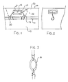
- the cathodic protection device is arranged for use in a concrete structure generally indicated at 10 having a reinforcing bar 11 embedded within the concrete and spaced from an upper surface 14 of the concrete.
- the present invention is primarily concerned with protection of the reinforcing bars buried in the concrete layer but also can advantageously be used with other steel members in the concrete such as supports for attachments which are partially buried with a surface or portion exposed beyond the concrete to receive the attachment.
- the present invention is primarily concerned with concrete structures but some aspects, such as the anode construction, can also be used with other situations where a steel element is buried within a covering layer. The following description is directed to the primary use, but not sole use, with concrete structures.
- a cathodic protection device Embedded within the concrete at a position adjacent to the reinforcing bar 11 is a cathodic protection device generally indicated at 15 which includes a puck-shaped anode body 16.
- the body 16 is preferably circular in plan view to define a circular upper surface 18 as shown in Figure 3 and has a cylindrical peripheral surface 17 as shown in Figure 1.
- Other shapes of the anode body can be provided if preferred but the puck is a convenient form in that it is relatively flat to allow insertion into the body of the concrete and it provides a sufficient volume of the anode material to avoid rapid depletion.
- a pair of connecting wires 19 and 20 which are flexible but sufficiently stiff to be self-supporting. Any suitable electrically conductive material such as copper or most preferably steel can be used.
- a layer of a mortar material 21 Around the anode body is provided a layer of a mortar material 21.
- the mortar material is moulded around the puck so as to provide a thickness of a mortar material around the full periphery and on the top and bottom surfaces of the puck with the thickness being of the order of 1cm.
- the wires 19 and 20 are electrically connected to the anode material and pass through the mortar.
- the mortar forms an electrolyte which is in intimate communication with the concrete layer so that ions can flow between the anode and the steel reinforcement.
- the mortar contains and supports also suitable materials to maintain the pH above 12 as described in the above application and preferably above 14 (the preferred value is approximately 14.5).
- Portland cements of intrinsically higher alkali content i.e. those containing relatively high proportions of Na 2 O and K 2 O
- other cements can be used with supplementary alkalis in the form of LiOH, NaOH or KOH for example.
- a humectant or deliquescent material In addition to the above materials, there is also applied into the mortar material a humectant or deliquescent material.
- Suitable materials include CaCl2, LiNO3, LiCl, MgCl2, Ca(SO4)2 and many others well known to one skilled in the art.
- Such deliquescent materials are basically in solid or powder form but can be dissolved to form an aqueous solution.
- the material can be supplied in the powder form in admixture with the cement in required proportions and added to the mix water in conventional manner.
- the material can be supplied in aqueous solution where some or all of the water is supplied in the solution.
- the deliquescent material is firmly bonded into the mortar material with the remaining materials set forth above.
- Other suitable deliquescent materials are set out in the above mentioned application, to which reference may be made. In all cases, therefore, the humectant or deliquescent material is carried in or bonded into the surrounding filler material and is not in a free flowing or liquid condition. It cannot therefore migrate in the concrete layer and remains in place in the filler material.
- the filler material is preferably a solid so that it can contain and hold the anode without danger of being displaced during the process. However gels and pastes can also be used.
- the filler material preferably is relatively porous so that it can accommodate expansion of the anode material during oxidation (corrosion) of the anode. However voids which might fill with water should be avoided.
- a covering fabric such as felt can also be used to support the additive materials which are allowed to dry in the fabric pores.
- the humectant material is thus selected so that it remains supported by and admixed into the mortar so that it can not migrate out of the mortar during storage or in use.
- the use of the protection device is substantially as described in the above application WO94/29496 in that it is buried in the concrete layer either at formation of the concrete in the original casting process or more preferably in a restoration process subsequent to the original casting.
- sufficient of the original concrete is excavated as indicated at the dashed lines 22 to allow the reinforcing bar 11 to be exposed.
- the wires 19 and 20 are then wrapped around the reinforcing bar and the protective device placed into position in the exposed opening.
- the device is then covered by a recast portion of concrete and remains in place buried within the concrete.
- This system is therefore generally applicable to a sacrificial anode system where the anode is buried within the concrete.
- the anode can form a pad applied onto the surface of the concrete with the filler material applied to and covering only one surface for contacting the concrete.
- the cathodic protection device therefore operates in the conventional manner in that electrolytic potential difference between the anode and the steel reinforcing member causes a current to flow therebetween through the electrical connection and causes ions to flow therebetween through the concrete sufficient to prevent or at least reduce corrosion of the steel reinforcing bar while causing corrosion of the anode.
- the level of the pH and the presence of the humectant enhances the maintenance of the current so that the current can be maintained for an extended period of time in a range 5 to 20 years.
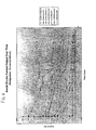
- the presence of the humectant material bound into the mortar layer acts to absorb sufficient moisture to maintain ion transfer around the anode to ensure that sufficient output current is maintained during the life of the anode and to keep the anode/filler interface electrochemically active. The presence also increases the amount of the current. Even though the mortar material 21 is not exposed to the atmosphere as it is buried within the concrete, and even though the deliquescent material is bound in fixed form into the mortar material, it has been found that absorption of moisture into the deliquescent material is sufficient to enhance the maintenance of the current output and to prevent premature reduction of output current over an extended period of operation and before the anode is consumed.
- figure 11 is shown a plurality of plots over time of current output for different additives in the mortar material. This shows that a significant increase is obtained in the current by using the humectant in the mortar both in combination with the alkali and without the alkali. While these observations are taken over only a relatively short time scale it can be reasonably predicted that the same advantages in current level will be maintained over an extended period of several years over the normal life of the anode.
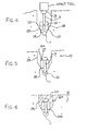
- the protective device works in a similar manner to that described above in that there is an anode body formed of a suitable material of the required electric potential and that body is electrically connected to the reinforcing bar 11 of the concrete structure 10.
- the body may be also surrounded by a mortar material 21A containing the materials described above; but also the surrounding material may be omitted.
- the mortar material is not carried by the anode body 16A but instead is applied as a subsequent process as a filler to an opening 22A.
- the opening 22A is a drilled opening which is formed as a cylindrical hole 25 drilled into the concrete extending down to a base 29 which is sufficiently deep within the concrete structure 10 so as to expose an upper part of the reinforcing bar 11. It is not essential that the reinforcing bar be completely exposed at its upper surface but it is preferred to do so to ensure that the reinforcing bar has indeed been properly located and that the subsequent connection is properly applied to the reinforcing bar without the possibility of missing the reinforcing bar and leaving an open electrical connection.
- a drilled hole therefore can suffice and the drilled hole need only have a diameter sufficient to receive the body 16A to ensure the body is wholly contained within the concrete structure 10 after the mortar material 21A is inserted in place to fill the hole 22A.
- the anode body 16A has a cylindrical outer surface 26, a circular top surface 27 and a circular bottom surface 28. Other shapes can also be adopted if preferred.
- the anode body 16A includes a central longitudinal bore 30. The bore 30 co-operates with an attachment pin 31 having an upper head 32 and lower pointed end 33.
- a kit of parts for assembling the structure would include a plurality of the anode bodies 16A and a plurality of the pins 31 for assembly into the drilled holes.
- the outside diameter of the pin 31 is slightly greater than the inside diameter of the hole 30 so that when driven through the hole 30, the pin is firmly engaged into the bore so that there is no possibility of the anode body becoming loose from the pin.
- the anode body may be pre-formed onto the pin as a rigid structure therewith and remains in place during the installation.
- the length of the pin 31 is selected so that it will pass through the bore 30 to a position where the head 32 engages the top surface 27 at which time the pointed lower end 33 is engaged into the reinforcing bar 11.
- Suitable impact tools are well-known in the construction industry for driving pins of this type into concrete and steel structures and such tools are well-known to one skilled in the art.
- the pin 31 is located at the top of the bore driven by the impact tool through the bore so that the lower end drives into the reinforcing bar and is attached thereto by cold forming of the reinforcing bar to provide a permanent physical attachment of the pin to the reinforcing bar.
- the pin stands vertically upwardly from the reinforcing bar and the anode body is held above the reinforcing bar by the pin. There is therefore no loose coupling and the attachment is entirely rigid so that it can not be disturbed during casting of the mortar material 21A or otherwise.
- the hole is shaped relative to the anode body so that the whole of the hole is filled with the filler material to prevent voids which can fill with water.
- the hole can be partly filled with the filler material which surrounds the anode body but not the complete hole, with the remainder of the hole being topped up with another filler which can simply be concrete.
- the mortar material contains the components necessary to enhance the maintenance of the electrolytic current between the anode body and the steel reinforcing bar.
- the enhancing components may be omitted or replaced and the advantageous mounting of the anode body used as described above.
- the anode can be formed of any suitable material which is electro-negative relative to the steel reinforcing members.
- Zinc is the preferred choice, but other materials such as magnesium, aluminum or alloys thereof can also be used.
- the covering layer is omitted and instead the humectant and/or the alkali and/or other enhancing agents as described hereinbefore are incorporated into the body of the anode.
- the body is formed of a material as described above and the enhancement agent is incorporated into the structure by one of a number of available techniques.
- the agent is admixed during casting of the anode material as a homogeneous mixture therewith.
- the materials of the anode and the agent can be finely divided and sintered or otherwise bonded together as an admixture.
- FIG 13 A yet further arrangement is shown in figure 13 wherein the anode material is supplied as a foil and the agent is supplied as a layer on one side of the foil which is then folded or rolled so as to form overlying layers of the material with the agent between such as a jellyroll or accordion folded structure.
- This arrangement provides a surface, such as the end surface of the jellyroll, on the anode body which is defined by the anode material with the agent directly available at the same surface.
- the humectant material is carried in a manner which allows a surface of the material of the anode body to communicate ions with the layer and which presents the agent at the same surface.
- the agent remains available at the surface to continue its action in enhancing the electrolytic effect.
- the only effect of the agent occurs at the interface and it is valueless if buried in the body or otherwise remote from the active surface.
- Yet further alternative techniques can use the anode material in mesh form with the agent in the pores or openings or can use drilled or otherwise formed holes in the body to receive the agent.
- This arrangement of providing the agent directly in the anode body allows the construction of an anode body which is of minimum dimensions thus allowing its installation in smaller locations or holes and thus allowing installation in locations where space is limited and thus reducing costs for forming the excavation to allow the installation.
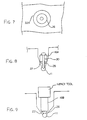
- the anode body 16A is enhanced by the addition of a supplementary body portion 35 of a different material.
- This body portion is formed of a metal which is of increased potential difference from the steel reinforcing bar relative to the main body of the anode, so that this anode body will provide an enhanced potential difference in an initial operating condition but the additional body will be consumed more quickly so that it becomes used up at an early stage.
- the additional body therefore provides a "kick start" to the process generating an initial high potential difference and then after it is consumed, the remaining process carries on through the use of the previously described anode body 16A.
- the additional body is applied simply in the form of a cylindrical washer at the lower end 27 of the body 16A so it can be applied in place and then the pin driven through the bore 30 and through a similar bore in the washer into the reinforcing bar 11 as previously described.
- the washer can thus be attached to the body 16A before use or can be a simple separate element.
- the washer can be applied at either end of the body on the pin and is held in place by the rigidity of the pin as previously described.
- FIG. 9 A further alternative is shown in Figure 9 where the pin 30 is replaced by a deformable block 36 of a flowable metal such as lead.
- the body 16B does not include a central bore but instead carries the lead block 36 on its lower end 27.
- the impact tool in this case therefore acts to drive a force through the body 16B into the flowable material block 36 so as to deform that material and bond it to the reinforcing bar 11 by the flowing action of the material.
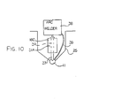
- FIG 10 is shown yet further alternative in which a pin 31A is provided already inserted through the body 16C.
- the hole 30 through the body 16C is arranged as a friction fit on the pin so that the pin is held in place without necessity for deformation of the body 16C.
- the pin thus has a lower end projecting downwardly from the underside of the body 16C and this lower end or tip 37 is welded to the upper surface of the reinforcing bar 11 by an arc welding system 38 of conventional type having a return wire 39 connected to the reinforcing bar generally at a separate location.
- the electrical current through the pin 31A acts to weld the lower end of the pin to the reinforcing bar to provide a permanent fixed upstanding pin holding the anode body 16C accurately in place within the drilled hole 25.
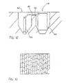
- FIG 12 is shown another alternative arrangement which uses two drilled holes 40 and 41.
- the reinforcing members are arranged at a depth of less than 2 inches which makes it difficult to provide an anode body which is sufficiently small to be received above the rebar and leave sufficient space for a filler material covering the anode body.
- the two hole arrangement thus allows a deeper second hole along side the rebar to receive and house the anode member and the first hole to receive a pin member which connects electrically to the rebar.
- the pin member uses one of the above techniques for attachment to the rebar.
- a small connecting groove 42 is formed between the drilled holes and a flexible conductor 43 attached to the anode 44 and to the pin member 45 passes through the groove.
- the drilled holes and the groove are filled as previously described.
- the anode can thus be installed in relatively small drilled holes and can be connected to the rebar to ensure effective electrical connection while having sufficient size to provide the required volume of sacrificial material for the required length of operating life.
- each anode is relativelylocalized so that the anodes must be installed in an array to provide protection for the whole reinforcing steel structure.
Landscapes
- Chemical & Material Sciences (AREA)
- Engineering & Computer Science (AREA)
- Materials Engineering (AREA)
- Mechanical Engineering (AREA)
- Metallurgy (AREA)
- Organic Chemistry (AREA)
- Prevention Of Electric Corrosion (AREA)
- Bipolar Transistors (AREA)
- Led Device Packages (AREA)
Applications Claiming Priority (3)
| Application Number | Priority Date | Filing Date | Title |
|---|---|---|---|
| US09/245,373 US6165346A (en) | 1999-02-05 | 1999-02-05 | Cathodic protection of concrete |
| US245373 | 1999-02-05 | ||
| PCT/CA2000/000101 WO2000046422A2 (en) | 1999-02-05 | 2000-02-02 | Cathodic protection |
Publications (2)
| Publication Number | Publication Date |
|---|---|
| EP1153159A1 EP1153159A1 (en) | 2001-11-14 |
| EP1153159B1 true EP1153159B1 (en) | 2005-11-16 |
Family
ID=22926404
Family Applications (1)
| Application Number | Title | Priority Date | Filing Date |
|---|---|---|---|
| EP00903438A Expired - Lifetime EP1153159B1 (en) | 1999-02-05 | 2000-02-02 | Cathodic protection |
Country Status (8)
| Country | Link |
|---|---|
| US (2) | US6165346A (enExample) |
| EP (1) | EP1153159B1 (enExample) |
| JP (1) | JP4574013B2 (enExample) |
| AT (1) | ATE310109T1 (enExample) |
| AU (1) | AU775457B2 (enExample) |
| CA (1) | CA2350059C (enExample) |
| DE (1) | DE60024061T2 (enExample) |
| WO (1) | WO2000046422A2 (enExample) |
Families Citing this family (39)
| Publication number | Priority date | Publication date | Assignee | Title |
|---|---|---|---|---|
| US6217742B1 (en) * | 1996-10-11 | 2001-04-17 | Jack E. Bennett | Cathodic protection system |
| GB9802805D0 (en) * | 1998-02-10 | 1998-04-08 | Atraverda Ltd | Electrochemical treatment of reinforced concrete |
| US6572760B2 (en) * | 1999-02-05 | 2003-06-03 | David Whitmore | Cathodic protection |
| US6165346A (en) | 1999-02-05 | 2000-12-26 | Whitmore; David | Cathodic protection of concrete |
| US7276144B2 (en) * | 1999-02-05 | 2007-10-02 | David Whitmore | Cathodic protection |
| US6358397B1 (en) * | 2000-09-19 | 2002-03-19 | Cor/Sci, Llc. | Doubly-protected reinforcing members in concrete |
| WO2003027356A1 (en) * | 2001-09-26 | 2003-04-03 | J.E. Bennett Consultants, Inc. | Cathodic protection system |
| JP3521195B2 (ja) | 2001-11-27 | 2004-04-19 | 電気化学工業株式会社 | モルタル又はコンクリート部材の鋼材腐食防止方法及びそれに用いる鋼材腐食防止材料 |
| US6793800B2 (en) * | 2002-12-20 | 2004-09-21 | David Whitmore | Cathodic protection of steel within a covering material |
| FR2859223B1 (fr) * | 2003-08-29 | 2005-11-18 | Bouygues Travaux Publics | Procede et dispositif pour la protection cathodique d'un ouvrage en beton arme partiellement immerge |
| CA2444638C (en) | 2003-10-10 | 2008-11-25 | David W. Whitmore | Cathodic protection of steel within a covering material |
| GB0409521D0 (en) * | 2004-04-29 | 2004-06-02 | Fosroc International Ltd | Sacrificial anode assembly |
| EP1759189A4 (en) * | 2004-06-03 | 2015-02-25 | John E Bennett | ANODE ASSEMBLY FOR CATHODE PROTECTION |
| GB2451725B8 (en) * | 2004-07-06 | 2019-05-01 | E Chem Tech Ltd | Protection of reinforcing steel |
| US8211289B2 (en) * | 2005-03-16 | 2012-07-03 | Gareth Kevin Glass | Sacrificial anode and treatment of concrete |
| US8999137B2 (en) | 2004-10-20 | 2015-04-07 | Gareth Kevin Glass | Sacrificial anode and treatment of concrete |
| GB2427618B8 (en) * | 2004-10-20 | 2019-05-01 | E Chem Tech Ltd | Improvements related to the protection of reinforcement |
| GB0505353D0 (en) | 2005-03-16 | 2005-04-20 | Chem Technologies Ltd E | Treatment process for concrete |
| CA2488298C (en) | 2004-11-23 | 2008-10-14 | Highline Mfg. Inc. | Bale processor with grain mixing attachment |
| BRPI0617969A2 (pt) * | 2005-10-04 | 2011-08-09 | Gareth Glass | uso de um ánodo e um preenchimento para proteger o aço na construção de concreto reforçado e combinação de um ánodo e um preenchimento |
| US7422665B2 (en) * | 2006-03-08 | 2008-09-09 | David Whitmore | Anode for cathodic protection |
| WO2007126715A2 (en) * | 2006-04-06 | 2007-11-08 | Bennett John E | Activating matrix for cathodic protection |
| US8157983B2 (en) * | 2007-03-24 | 2012-04-17 | Bennett John E | Composite anode for cathodic protection |
| AU2009281686B2 (en) | 2008-08-11 | 2015-01-29 | Wolfgang Schwarz | Hydraulic binding agent and binding agent matrixes produced thereof |
| GB2464346A (en) * | 2008-10-17 | 2010-04-21 | Gareth Kevin Glass | Repair of reinforced concrete structures using sacrificial anodes |
| US7998321B1 (en) | 2009-07-27 | 2011-08-16 | Roberto Giorgini | Galvanic anode for reinforced concrete applications |
| US8361286B1 (en) | 2009-07-27 | 2013-01-29 | Roberto Giorgini | Galvanic anode for reinforced concrete applications |
| US8394193B2 (en) | 2009-08-10 | 2013-03-12 | Wolfgang Schwarz | Hydraulic binder and binder matrices made thereof |
| US10053782B2 (en) | 2012-07-19 | 2018-08-21 | Vector Corrosion Technologies Ltd. | Corrosion protection using a sacrificial anode |
| US8968549B2 (en) | 2012-07-19 | 2015-03-03 | Vector Corrosion Technologies Ltd. | Two stage cathodic protection system using impressed current and galvanic action |
| US8961746B2 (en) | 2012-07-19 | 2015-02-24 | Vector Corrosion Technologies Ltd. | Charging a sacrificial anode with ions of the sacrificial material |
| EP3623499A1 (en) | 2012-07-19 | 2020-03-18 | Vector Corrosion Technologies Ltd | Corrosion protection using a sacrificial anode |
| USRE50006E1 (en) | 2012-07-19 | 2024-06-11 | Vector Corrosion Technologies Ltd. | Corrosion protection using a sacrificial anode |
| US10227698B2 (en) | 2012-07-30 | 2019-03-12 | Construction Research & Technology Gmbh | Galvanic anode and method of corrosion protection |
| JP6239992B2 (ja) * | 2014-02-04 | 2017-11-29 | 株式会社ナカボーテック | 電気防食用バックフィル |
| JP6353733B2 (ja) * | 2014-08-04 | 2018-07-04 | デンカ株式会社 | コンクリート内の鋼材の防食機能を有したスペーサー部材およびその設置方法 |
| US9909220B2 (en) | 2014-12-01 | 2018-03-06 | Vector Corrosion Technologies Ltd. | Fastening sacrificial anodes to reinforcing bars in concrete for cathodic protection |
| US10570523B2 (en) | 2017-08-25 | 2020-02-25 | David William Whitmore | Manufacture of sacrificial anodes |
| CN115504748B (zh) * | 2022-10-28 | 2023-06-20 | 广州市克来斯特建材科技有限公司 | 一种牺牲阳极保护层砂浆及其制备方法和应用 |
Family Cites Families (34)
| Publication number | Priority date | Publication date | Assignee | Title |
|---|---|---|---|---|
| US1269926A (en) | 1918-01-07 | 1918-06-18 | Carlos Idaho Gesell | Rust prevention. |
| US2193667A (en) | 1937-12-18 | 1940-03-12 | Woldemar A Bary | Apparatus for electrolytic protection of vessels |
| US2565544A (en) | 1946-08-28 | 1951-08-28 | Aluminum Co Of America | Cathodic protection and underground metallic structure embodying the same |
| BE521935A (enExample) | 1952-08-05 | |||
| US3414496A (en) | 1965-10-20 | 1968-12-03 | Continental Oil Co | Controlled potential protection of metallic vessel-latex solution systems |
| US3488275A (en) | 1967-05-11 | 1970-01-06 | Kaiser Aluminium Chem Corp | Cathodic protection system |
| NL7608443A (en) | 1976-07-29 | 1978-01-31 | Drs P J H Willems En H K M Bus | Combating rust formation in reinforced concrete - by drilling and inserting a metal, esp. aluminium, which is more electropositive than the reinforcement |
| US4265725A (en) * | 1979-07-20 | 1981-05-05 | C. E. Equipment Co., Inc. | Anode connection |
| US4435264A (en) | 1982-03-01 | 1984-03-06 | The Dow Chemical Company | Magnesium anode backfills |
| US4506485A (en) | 1983-04-12 | 1985-03-26 | State Of California, Department Of Transportation | Process for inhibiting corrosion of metal embedded in concrete and a reinforced concrete construction |
| US4692066A (en) | 1986-03-18 | 1987-09-08 | Clear Kenneth C | Cathodic protection of reinforced concrete in contact with conductive liquid |
| US4874487A (en) | 1986-07-18 | 1989-10-17 | Raychem Corporation | Corrosion protection |
| US4957612A (en) | 1987-02-09 | 1990-09-18 | Raychem Corporation | Electrodes for use in electrochemical processes |
| US5183694A (en) | 1988-04-19 | 1993-02-02 | Webb Michael G | Inhibiting corrosion in reinforced concrete |
| DE3826926A1 (de) * | 1988-08-09 | 1990-02-15 | Heraeus Elektroden | Anode fuer kathodischen korrosionsschutz |
| CA2040610A1 (en) | 1990-05-21 | 1991-11-22 | John E. Bennett | Apparatus for the removal of chloride from reinforced concrete structures |
| GB9015743D0 (en) * | 1990-07-17 | 1990-09-05 | Pithouse Kenneth B | The protection of cementitious material |
| US5141607A (en) | 1990-07-31 | 1992-08-25 | Corrpro Companies, Inc. | Method and apparatus for the removal of chlorides from steel reinforced concrete structures |
| US5292411A (en) * | 1990-09-07 | 1994-03-08 | Eltech Systems Corporation | Method and apparatus for cathodically protecting reinforced concrete structures |
| GB9102904D0 (en) | 1991-02-12 | 1991-03-27 | Ici America Inc | Modified cementitious composition |
| US5174871A (en) | 1991-06-27 | 1992-12-29 | Interprovincial Corrosion Control Company Limited | Method for providing cathodic protection of underground structures |
| GB9126899D0 (en) | 1991-12-19 | 1992-02-19 | Aston Material Services Ltd | Improvements in and relating to treatments for concrete |
| GB9215502D0 (en) | 1992-07-21 | 1992-09-02 | Ici Plc | Cathodic protection system and a coating and coating composition therefor |
| US5366670A (en) | 1993-05-20 | 1994-11-22 | Giner, Inc. | Method of imparting corrosion resistance to reinforcing steel in concrete structures |
| US6303017B1 (en) | 1993-06-16 | 2001-10-16 | Aston Material Services Limited | Cathodic protection of reinforced concrete |
| GB9312431D0 (en) * | 1993-06-16 | 1993-07-28 | Aston Material Services Ltd | Improvements in and relating to protecting reinforced concrete |
| US5650060A (en) | 1994-01-28 | 1997-07-22 | Minnesota Mining And Manufacturing Company | Ionically conductive agent, system for cathodic protection of galvanically active metals, and method and apparatus for using same |
| US5505826A (en) | 1994-11-30 | 1996-04-09 | Haglin; Patrick G. | Hydrophilic anode corrosion control system |
| AU5257996A (en) | 1995-03-24 | 1996-10-16 | Alltrista Corporation | Jacketed sacrificial anode cathodic protection system |
| US6033553A (en) * | 1996-10-11 | 2000-03-07 | Bennett; Jack E. | Cathodic protection system |
| US6471851B1 (en) * | 1996-10-11 | 2002-10-29 | Jack E. Bennett | Cathodic protection system |
| US5968339A (en) * | 1997-08-28 | 1999-10-19 | Clear; Kenneth C. | Cathodic protection system for reinforced concrete |
| GB9802805D0 (en) | 1998-02-10 | 1998-04-08 | Atraverda Ltd | Electrochemical treatment of reinforced concrete |
| US6165346A (en) | 1999-02-05 | 2000-12-26 | Whitmore; David | Cathodic protection of concrete |
-
1999
- 1999-02-05 US US09/245,373 patent/US6165346A/en not_active Ceased
-
2000
- 2000-02-02 AT AT00903438T patent/ATE310109T1/de not_active IP Right Cessation
- 2000-02-02 CA CA002350059A patent/CA2350059C/en not_active Expired - Fee Related
- 2000-02-02 DE DE60024061T patent/DE60024061T2/de not_active Expired - Lifetime
- 2000-02-02 JP JP2000597479A patent/JP4574013B2/ja not_active Expired - Fee Related
- 2000-02-02 EP EP00903438A patent/EP1153159B1/en not_active Expired - Lifetime
- 2000-02-02 AU AU25275/00A patent/AU775457B2/en not_active Ceased
- 2000-02-02 WO PCT/CA2000/000101 patent/WO2000046422A2/en not_active Ceased
-
2006
- 2006-10-24 US US11/585,305 patent/USRE40672E1/en not_active Expired - Lifetime
Also Published As
| Publication number | Publication date |
|---|---|
| WO2000046422A3 (en) | 2000-12-07 |
| JP2002536544A (ja) | 2002-10-29 |
| US6165346A (en) | 2000-12-26 |
| ATE310109T1 (de) | 2005-12-15 |
| CA2350059C (en) | 2005-05-03 |
| WO2000046422A2 (en) | 2000-08-10 |
| EP1153159A1 (en) | 2001-11-14 |
| USRE40672E1 (en) | 2009-03-24 |
| DE60024061T2 (de) | 2006-07-20 |
| HK1038044A1 (en) | 2002-03-01 |
| DE60024061D1 (de) | 2005-12-22 |
| JP4574013B2 (ja) | 2010-11-04 |
| AU775457B2 (en) | 2004-08-05 |
| AU2527500A (en) | 2000-08-25 |
| CA2350059A1 (en) | 2000-08-10 |
Similar Documents
| Publication | Publication Date | Title |
|---|---|---|
| EP1153159B1 (en) | Cathodic protection | |
| US6572760B2 (en) | Cathodic protection | |
| EP2880200B1 (en) | Galvanic anode and method of corrosion protection | |
| CA2562450C (en) | Sacrificial anode assembly | |
| US8211289B2 (en) | Sacrificial anode and treatment of concrete | |
| US20070194774A1 (en) | Anode Assembly For Cathodic Protection | |
| US8157983B2 (en) | Composite anode for cathodic protection | |
| CA2509549C (en) | Cathodic protection of steel within a covering material | |
| EP0186334A1 (en) | Cathodic protection system for reinforcing bars in concrete, a method of carrying out such protection and an anode for use in the method and system | |
| HK1038044B (en) | Cathodic protection | |
| WO2008118589A1 (en) | Composite anode for cathodic protection | |
| EP2132360A1 (en) | Composite anode for cathodic protection background of the invention | |
| USRE49882E1 (en) | Corrosion protection using a sacrificial anode | |
| AU2015200284A1 (en) | Corrosion protection using a sacrifical anode |
Legal Events
| Date | Code | Title | Description |
|---|---|---|---|
| PUAI | Public reference made under article 153(3) epc to a published international application that has entered the european phase |
Free format text: ORIGINAL CODE: 0009012 |
|
| 17P | Request for examination filed |
Effective date: 20010824 |
|
| AK | Designated contracting states |
Kind code of ref document: A1 Designated state(s): AT BE CH CY DE DK ES FI FR GB GR IE IT LI LU MC NL PT SE |
|
| AX | Request for extension of the european patent |
Free format text: AL;LT;LV;MK;RO;SI |
|
| 17Q | First examination report despatched |
Effective date: 20020710 |
|
| GRAP | Despatch of communication of intention to grant a patent |
Free format text: ORIGINAL CODE: EPIDOSNIGR1 |
|
| GRAS | Grant fee paid |
Free format text: ORIGINAL CODE: EPIDOSNIGR3 |
|
| GRAA | (expected) grant |
Free format text: ORIGINAL CODE: 0009210 |
|
| AK | Designated contracting states |
Kind code of ref document: B1 Designated state(s): AT BE CH CY DE DK ES FI FR GB GR IE IT LI LU MC NL PT SE |
|
| PG25 | Lapsed in a contracting state [announced via postgrant information from national office to epo] |
Ref country code: BE Free format text: LAPSE BECAUSE OF FAILURE TO SUBMIT A TRANSLATION OF THE DESCRIPTION OR TO PAY THE FEE WITHIN THE PRESCRIBED TIME-LIMIT Effective date: 20051116 Ref country code: NL Free format text: LAPSE BECAUSE OF FAILURE TO SUBMIT A TRANSLATION OF THE DESCRIPTION OR TO PAY THE FEE WITHIN THE PRESCRIBED TIME-LIMIT Effective date: 20051116 Ref country code: FI Free format text: LAPSE BECAUSE OF FAILURE TO SUBMIT A TRANSLATION OF THE DESCRIPTION OR TO PAY THE FEE WITHIN THE PRESCRIBED TIME-LIMIT Effective date: 20051116 Ref country code: AT Free format text: LAPSE BECAUSE OF FAILURE TO SUBMIT A TRANSLATION OF THE DESCRIPTION OR TO PAY THE FEE WITHIN THE PRESCRIBED TIME-LIMIT Effective date: 20051116 |
|
| REG | Reference to a national code |
Ref country code: GB Ref legal event code: FG4D |
|
| REG | Reference to a national code |
Ref country code: CH Ref legal event code: EP |
|
| REG | Reference to a national code |
Ref country code: IE Ref legal event code: FG4D |
|
| REF | Corresponds to: |
Ref document number: 60024061 Country of ref document: DE Date of ref document: 20051222 Kind code of ref document: P |
|
| REG | Reference to a national code |
Ref country code: HK Ref legal event code: GR Ref document number: 1038044 Country of ref document: HK |
|
| PG25 | Lapsed in a contracting state [announced via postgrant information from national office to epo] |
Ref country code: IE Free format text: LAPSE BECAUSE OF NON-PAYMENT OF DUE FEES Effective date: 20060202 |
|
| PG25 | Lapsed in a contracting state [announced via postgrant information from national office to epo] |
Ref country code: DK Free format text: LAPSE BECAUSE OF FAILURE TO SUBMIT A TRANSLATION OF THE DESCRIPTION OR TO PAY THE FEE WITHIN THE PRESCRIBED TIME-LIMIT Effective date: 20060216 Ref country code: SE Free format text: LAPSE BECAUSE OF FAILURE TO SUBMIT A TRANSLATION OF THE DESCRIPTION OR TO PAY THE FEE WITHIN THE PRESCRIBED TIME-LIMIT Effective date: 20060216 Ref country code: GR Free format text: LAPSE BECAUSE OF FAILURE TO SUBMIT A TRANSLATION OF THE DESCRIPTION OR TO PAY THE FEE WITHIN THE PRESCRIBED TIME-LIMIT Effective date: 20060216 |
|
| PG25 | Lapsed in a contracting state [announced via postgrant information from national office to epo] |
Ref country code: ES Free format text: LAPSE BECAUSE OF FAILURE TO SUBMIT A TRANSLATION OF THE DESCRIPTION OR TO PAY THE FEE WITHIN THE PRESCRIBED TIME-LIMIT Effective date: 20060227 |
|
| PG25 | Lapsed in a contracting state [announced via postgrant information from national office to epo] |
Ref country code: LU Free format text: LAPSE BECAUSE OF NON-PAYMENT OF DUE FEES Effective date: 20060228 Ref country code: MC Free format text: LAPSE BECAUSE OF NON-PAYMENT OF DUE FEES Effective date: 20060228 |
|
| PG25 | Lapsed in a contracting state [announced via postgrant information from national office to epo] |
Ref country code: PT Free format text: LAPSE BECAUSE OF FAILURE TO SUBMIT A TRANSLATION OF THE DESCRIPTION OR TO PAY THE FEE WITHIN THE PRESCRIBED TIME-LIMIT Effective date: 20060417 |
|
| REG | Reference to a national code |
Ref country code: CH Ref legal event code: NV Representative=s name: KATZAROV S.A. |
|
| NLV1 | Nl: lapsed or annulled due to failure to fulfill the requirements of art. 29p and 29m of the patents act | ||
| ET | Fr: translation filed | ||
| PLBE | No opposition filed within time limit |
Free format text: ORIGINAL CODE: 0009261 |
|
| STAA | Information on the status of an ep patent application or granted ep patent |
Free format text: STATUS: NO OPPOSITION FILED WITHIN TIME LIMIT |
|
| 26N | No opposition filed |
Effective date: 20060817 |
|
| REG | Reference to a national code |
Ref country code: IE Ref legal event code: MM4A |
|
| PG25 | Lapsed in a contracting state [announced via postgrant information from national office to epo] |
Ref country code: CY Free format text: LAPSE BECAUSE OF FAILURE TO SUBMIT A TRANSLATION OF THE DESCRIPTION OR TO PAY THE FEE WITHIN THE PRESCRIBED TIME-LIMIT Effective date: 20051116 |
|
| PGFP | Annual fee paid to national office [announced via postgrant information from national office to epo] |
Ref country code: CH Payment date: 20130220 Year of fee payment: 14 |
|
| REG | Reference to a national code |
Ref country code: CH Ref legal event code: PL |
|
| PG25 | Lapsed in a contracting state [announced via postgrant information from national office to epo] |
Ref country code: LI Free format text: LAPSE BECAUSE OF NON-PAYMENT OF DUE FEES Effective date: 20140228 Ref country code: CH Free format text: LAPSE BECAUSE OF NON-PAYMENT OF DUE FEES Effective date: 20140228 |
|
| REG | Reference to a national code |
Ref country code: FR Ref legal event code: PLFP Year of fee payment: 17 |
|
| PGFP | Annual fee paid to national office [announced via postgrant information from national office to epo] |
Ref country code: DE Payment date: 20160218 Year of fee payment: 17 |
|
| REG | Reference to a national code |
Ref country code: DE Ref legal event code: R082 Ref document number: 60024061 Country of ref document: DE Representative=s name: JOSTARNDT PATENTANWALTS-AG, DE |
|
| REG | Reference to a national code |
Ref country code: FR Ref legal event code: PLFP Year of fee payment: 18 |
|
| REG | Reference to a national code |
Ref country code: DE Ref legal event code: R119 Ref document number: 60024061 Country of ref document: DE |
|
| PG25 | Lapsed in a contracting state [announced via postgrant information from national office to epo] |
Ref country code: DE Free format text: LAPSE BECAUSE OF NON-PAYMENT OF DUE FEES Effective date: 20170901 |
|
| REG | Reference to a national code |
Ref country code: FR Ref legal event code: PLFP Year of fee payment: 19 |
|
| PGFP | Annual fee paid to national office [announced via postgrant information from national office to epo] |
Ref country code: GB Payment date: 20180216 Year of fee payment: 19 |
|
| PGFP | Annual fee paid to national office [announced via postgrant information from national office to epo] |
Ref country code: IT Payment date: 20180227 Year of fee payment: 19 Ref country code: FR Payment date: 20180222 Year of fee payment: 19 |
|
| GBPC | Gb: european patent ceased through non-payment of renewal fee |
Effective date: 20190202 |
|
| PG25 | Lapsed in a contracting state [announced via postgrant information from national office to epo] |
Ref country code: GB Free format text: LAPSE BECAUSE OF NON-PAYMENT OF DUE FEES Effective date: 20190202 |
|
| PG25 | Lapsed in a contracting state [announced via postgrant information from national office to epo] |
Ref country code: IT Free format text: LAPSE BECAUSE OF NON-PAYMENT OF DUE FEES Effective date: 20190202 Ref country code: FR Free format text: LAPSE BECAUSE OF NON-PAYMENT OF DUE FEES Effective date: 20190228 |