EP1152892B1 - Schneideinsatz für drehbearbeitung - Google Patents
Schneideinsatz für drehbearbeitung Download PDFInfo
- Publication number
- EP1152892B1 EP1152892B1 EP00908176A EP00908176A EP1152892B1 EP 1152892 B1 EP1152892 B1 EP 1152892B1 EP 00908176 A EP00908176 A EP 00908176A EP 00908176 A EP00908176 A EP 00908176A EP 1152892 B1 EP1152892 B1 EP 1152892B1
- Authority
- EP
- European Patent Office
- Prior art keywords
- edge
- bisector
- corner
- cutting
- land
- Prior art date
- Legal status (The legal status is an assumption and is not a legal conclusion. Google has not performed a legal analysis and makes no representation as to the accuracy of the status listed.)
- Expired - Lifetime
Links
Images
Classifications
-
- B—PERFORMING OPERATIONS; TRANSPORTING
- B23—MACHINE TOOLS; METAL-WORKING NOT OTHERWISE PROVIDED FOR
- B23B—TURNING; BORING
- B23B27/00—Tools for turning or boring machines; Tools of a similar kind in general; Accessories therefor
- B23B27/14—Cutting tools of which the bits or tips or cutting inserts are of special material
- B23B27/141—Specially shaped plate-like cutting inserts, i.e. length greater or equal to width, width greater than or equal to thickness
- B23B27/143—Specially shaped plate-like cutting inserts, i.e. length greater or equal to width, width greater than or equal to thickness characterised by having chip-breakers
-
- B—PERFORMING OPERATIONS; TRANSPORTING
- B23—MACHINE TOOLS; METAL-WORKING NOT OTHERWISE PROVIDED FOR
- B23B—TURNING; BORING
- B23B2200/00—Details of cutting inserts
- B23B2200/20—Top or side views of the cutting edge
- B23B2200/201—Details of the nose radius and immediately surrounding area
-
- B—PERFORMING OPERATIONS; TRANSPORTING
- B23—MACHINE TOOLS; METAL-WORKING NOT OTHERWISE PROVIDED FOR
- B23B—TURNING; BORING
- B23B2200/00—Details of cutting inserts
- B23B2200/36—Other features of cutting inserts not covered by B23B2200/04 - B23B2200/32
- B23B2200/3645—Lands, i.e. the outer peripheral section of the rake face
- B23B2200/3654—Lands, i.e. the outer peripheral section of the rake face being variable
-
- Y—GENERAL TAGGING OF NEW TECHNOLOGICAL DEVELOPMENTS; GENERAL TAGGING OF CROSS-SECTIONAL TECHNOLOGIES SPANNING OVER SEVERAL SECTIONS OF THE IPC; TECHNICAL SUBJECTS COVERED BY FORMER USPC CROSS-REFERENCE ART COLLECTIONS [XRACs] AND DIGESTS
- Y10—TECHNICAL SUBJECTS COVERED BY FORMER USPC
- Y10T—TECHNICAL SUBJECTS COVERED BY FORMER US CLASSIFICATION
- Y10T407/00—Cutters, for shaping
- Y10T407/23—Cutters, for shaping including tool having plural alternatively usable cutting edges
- Y10T407/235—Cutters, for shaping including tool having plural alternatively usable cutting edges with integral chip breaker, guide or deflector
-
- Y—GENERAL TAGGING OF NEW TECHNOLOGICAL DEVELOPMENTS; GENERAL TAGGING OF CROSS-SECTIONAL TECHNOLOGIES SPANNING OVER SEVERAL SECTIONS OF THE IPC; TECHNICAL SUBJECTS COVERED BY FORMER USPC CROSS-REFERENCE ART COLLECTIONS [XRACs] AND DIGESTS
- Y10—TECHNICAL SUBJECTS COVERED BY FORMER USPC
- Y10T—TECHNICAL SUBJECTS COVERED BY FORMER US CLASSIFICATION
- Y10T407/00—Cutters, for shaping
- Y10T407/24—Cutters, for shaping with chip breaker, guide or deflector
- Y10T407/245—Cutters, for shaping with chip breaker, guide or deflector comprising concave surface in cutting face of tool
Definitions
- the present invention relates to an indexable insert for turning according to the preamble of claim 1.
- an insert is e.g. described in document SU1782196.
- indexable inserts are used with nose point angles below 60°, wherein an ordinary value on the nose point angles is 55°, which enables application of the cutting inserts within a broad range.
- types rhomboidic, rhombic and regular triangular indexable inserts can be mentioned.
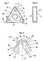
- Figs. 1-3 show a cutting insert 10 for copying turning according to the invention with triangular basic form.
- the cutting insert is generally made of cemented carbide but can also be made of other ceramic materials.
- the insert comprises flat top and bottom surfaces 11 and 12, which are mutually parallel and which form a right angle with the edge surfaces which are designated 13, 14 and 15 and interconnected by curved-corner portions.
- the edge surfaces are oriented in a plane perpendicular to the plane that includes flat surfaces 11 and 12.
- the insert additionally includes a plurality of cutting edges 18, 19 which, provide intersections between the edge surfaces 13, 14, 15 and the top surface 11.
- the insert can alternatively have positive basic shape wherein the edge surfaces intersect with the top surface at an acute angle.
- the insert has a central hole 16 for the receipt of a pin or a centre screw (not shown) for the clamping of the insert into a belonging tool holder 17 (Fig. 4).
- the edge surfaces extending towards an acute angled corner are designated 13 and 14, with the embodiment shown in Fig. 1 the edge 18 represents a secondary cutting edge and the edge 19 represents a main cutting edge between which then is an asymmetric curved corner region including a radial edge 20 on one side of the bisector B intended to serve as a wiper edge and on opposite side of said bisector there is a corner edge 21 adjacent to the main cutting edge 19. It is to be understood that the insert must have such inclination that a clearance angle is obtained at the main cutting edge and at the secondary cutting edges 18, 19 and at the corner region therebetween.
- edge portion 20 This will enable the edge portion 20 to be used as an edge for inwards copying such that when facing at for example 90° a large cut can be taken while the length of the edges 18 need not be specifically great.
- the insert is at all cutting edge portions provided with a land 22 which extends all around the insert whilst oriented substantially perpendicular towards the edge surface 13, 14, 15.
- the radial edge 20 is provided with a size of radius that is at least five times larger than the size valid for the corner edge 21 located on the opposite side of said bisector B, said corner edge being a transition to the main cutting edge 19.
- the main cutting edge 19 extends in a longitudinal direction such that it includes an angle of 80-135° together with radial edge 20.
- the transition between the primary radial edge 20 and the corner edge 21 is in the form of a secondary radial edge 23, the size of which ought to be less than the radial edge 24 that represents a transition between the primary radial edge 20 and the secondary cutting edge 18.
- the relation should preferably be such that the size of radius of radial edge 23 is about half the size of radial edge 24 located next to the secondary edge 18.
- a transition radial edge 25 ought to be provided between the corner edge 21 and the main cutting edge 19, the radius of which ought to be of same size as the size of the radius of radial edge 24 located next to the secondary edge 18.
- width of the land 22 along radial edge 20 and along the remainder of the insert it has been found suitable to select the width of said land 22 along radial edge 20 such that it amounts to 50-70 % of the width of the land 22 along the corner cutting edge 21.
- a sloping surface or downwards inclined surface 26 extends from the inner limiting edge of each land 22 and extends into a secondary sloping surface 27 which is located at the corner area.
- This secondary sloping surface 27 extends into a planar central floor surface 28 of triangular basic shape whilst plane parallel with the bottom face 12 of the insert.
- the angle of inclination a of said sloping surface 26 ought to be in the area 10-30° whereas the angle of inclination of the secondary sloping surface 27 ought to be 0-15°.
- Each land 22 is planar and includes a raised land area, which in a direction away from the corner area extends into an inclined land area.
- a characteristic feature of the invention is that said land area 22 includes an area 22' with smaller width along the radial edge 20 which then successively appears with larger width which is uniform both along the corner cutting edge 21 as well as along the entire main cutting edge 19. At the same time as this brings about a purposeful enforcement of the cutting edge this simultaneously enables reducing the contact between the chips and the insert's surface such that the crater wear effect can be timely deferred.
- a chip former is provided in the corner region.
- This chipformer is provided in the shape of an inclined plateau 27 that is depressed in relation to the edge portions, the confining side surfaces of which converge towards the corner with an asymmetric configuration in relation to the bisector. More specifically the shape is such that an essentially sine-formed side edge 29 located on same side of the bisector B as the primary radial edge 20 gets a termination in the form of an inclined primary edge 30 which extends parallel with radial edge 20 and then provides an obtuse angled corner 31 and then extends into a secondary edge 32 in opposite direction whereby said bisector B intersects said latter edge approximately in the middle thereof.
- the last mentioned secondary edge 32 provides in its turn an obtuse angled corner 33 together with the forward termination of another mainly sine-formed side edge 34 which represents a side confining edge of the plateau 27.
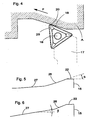
- Fig. 4 it is shown how the illustrated embodiment of the insert is used for copying inwards with the insert clamped into a belonging toolholder 17 whereby the direction of machining is designated P on the workpiece A.
Landscapes
- Engineering & Computer Science (AREA)
- Mechanical Engineering (AREA)
- Cutting Tools, Boring Holders, And Turrets (AREA)
- Milling Processes (AREA)
- Joining Of Corner Units Of Frames Or Wings (AREA)
Claims (7)
- Wendeschneideinsatz für die Drehbearbeitung mit im allgemeinen polygonaler Gestalt, mit einer oberen Fläche (11) und einer Bodenfläche (12) und diese verbindenden Kantenflächen (13, 14, 15), wobei mindestens ein Teil der Schnittlinien zwischen den Kantenflächen und der oberen Fläche mindestens eine Hauptschneidkanbe (19), eine Nebenschneidkante (18) und einen gekrümmten Eckenbereich dazwischen bildet, welcher asymmetrisch und in eine Vielzahl von kreisförmigen Segmenten geteilt ist, welche an der Schnittlinie mit der oberen Fläche Kantenabschnitte bilden, wobei unmittelbar benachbarte Kreissegmente gegenseitig unterschiedliche Radien haben, eine sekundäre Schneid- oder Nebenschneidkante (18) sich neben eine radiale Kante (20) erstreckt, die auf derselben Seite der Winkelhalbierenden angeordnet ist wie die Nebenschneidkante (18) und mit einem Krümmungsradius erscheint, dessen Abmessung mindestens fünfmal größer ist als die Ekkenkante (21), die auf der gegenüberliegenden Seite der Winkelhalbierenden angeordnet ist und einen Übergang zu der Hauptschneidkante (19) vorsieht, dadurch gekennzeichnet, daßa) der Einsatz die Gestalt eines regulären, polygonförmigen Körpers hat,b) daß die Übergangsfläche zwischen den Schneidkanten (18, 19) und der oberen Fläche (11) die Form einer kantenvetstärkenden Fase (22) solcher Gestalt hat, daß die Breite des Fasenabschnitts (22') längs der radialen Kante (20) auf einer Seite der Winkelhalbierenden (B) kleiner ist als die Breite der Fase (22) längs der gekrümmten Eckenschneidkante (21), die auf der gegenüberliegenden Seite der Winkelhalbierenden (B) angeordnet ist
- Wendeeinsatz nach Anspruch 1, dadurch gekennzeichnet, daß die Breite der die Kante verstärkenden Fase (22) dieselbe längs der gekrümmten Eckenschneidkante (21) wie längs der geraden Nebenschneidkante (18) ist
- Wendeeinsatz nach einem der Ansprüche 1-2, dadurch gekennzeichnet, daß die Breite der Fase (22) längs der radialen Kante (20) 50-70% der Breite der Fase längs der Eckenschneidkante (21) ausmacht
- Wendeeinsatz nach einem der Ansprüche 1-3, dadurch gekennzeichnet, daß der Einsatz in dem Eckenbereich in einem gewissen Abstand von der Fase (22) mit einer ebenen geneigten Fläche (27) erscheint, die in Bezug auf die Ksnten abgesenkt ist, während sie durch sinusförmige Seiten-Begrenzungskanten (29, 34) begrenzt ist, die nach außen zu der Schneidecke hin konvergieren.
- Wendeeinsatz nach Anspruch 4, dadurch gekennzeichnet, daß die sinusförmige Seiten-Begrenzungskante (29) sich auf einer Seite der Winkelhalbierenden (B) in eine hauptsächlich gerade Primärkante (30) erstreckt, die ganz auf einer Seite der Winkelhalbierenden (B) parallel zu der Verlängerung der radialen Kante (20) angeordnet ist.
- Wendeeinsatz nach Anspruch 4 oder 5, dadurch gekennzeichnet, daß sich die gerade Kante (30) über eine stumpf angewinkette Ecke (31) in eine andere gerade Kante (32) erstreckt, welche von der Winkelhalbierenden (B) geschnitten wird.
- Wendeeinsatz nach Anspruch 6, dadurch gekennzeichnet, daß die Winkelhalbierende (B) die gerade Nebenkante (32) hauptsächlich in ihrer Mitte schneidet.
Applications Claiming Priority (3)
| Application Number | Priority Date | Filing Date | Title |
|---|---|---|---|
| SE9900528A SE517274C2 (sv) | 1999-02-15 | 1999-02-15 | Vändskär för svarvning |
| SE9900528 | 1999-02-15 | ||
| PCT/SE2000/000262 WO2000047405A1 (en) | 1999-02-15 | 2000-02-10 | Cutting insert for turning |
Publications (2)
| Publication Number | Publication Date |
|---|---|
| EP1152892A1 EP1152892A1 (de) | 2001-11-14 |
| EP1152892B1 true EP1152892B1 (de) | 2005-07-27 |
Family
ID=20414495
Family Applications (1)
| Application Number | Title | Priority Date | Filing Date |
|---|---|---|---|
| EP00908176A Expired - Lifetime EP1152892B1 (de) | 1999-02-15 | 2000-02-10 | Schneideinsatz für drehbearbeitung |
Country Status (7)
| Country | Link |
|---|---|
| US (1) | US6786682B1 (de) |
| EP (1) | EP1152892B1 (de) |
| JP (1) | JP4520045B2 (de) |
| AT (1) | ATE300422T1 (de) |
| DE (1) | DE60021529T8 (de) |
| SE (1) | SE517274C2 (de) |
| WO (1) | WO2000047405A1 (de) |
Cited By (1)
| Publication number | Priority date | Publication date | Assignee | Title |
|---|---|---|---|---|
| EP3006140A1 (de) * | 2014-10-08 | 2016-04-13 | Sandvik Intellectual Property AB | Dreheinsatz und Drehwerkzeug |
Families Citing this family (20)
| Publication number | Priority date | Publication date | Assignee | Title |
|---|---|---|---|---|
| SE523620C2 (sv) * | 2001-10-01 | 2004-05-04 | Sandvik Ab | Skär för spånavskiljande bearbetning med ytavstrykande eggsegment. |
| SE525829C2 (sv) * | 2002-06-26 | 2005-05-10 | Seco Tools Ab | Dubbelsidigt vändskär med bomberad biskäregg samt tillverkningsmetod för skäret |
| DE102004026601A1 (de) | 2004-06-01 | 2005-12-22 | Sandvik Ab | Wendeschneideinsatz zum Drehen |
| AT8433U1 (de) * | 2005-03-11 | 2006-08-15 | Ceratizit Austria Gmbh | Wendeschneidplatte |
| SE530780C2 (sv) * | 2006-01-10 | 2008-09-09 | Sandvik Intellectual Property | Indexerbart skär med olika släppningsvinklar samt svarvverktyg |
| SE530090C2 (sv) * | 2006-06-27 | 2008-02-26 | Sandvik Intellectual Property | Planfrässkär med flera bågformiga deleggar och konvexa släppningsytor |
| JP4990374B2 (ja) * | 2007-02-16 | 2012-08-01 | デグテック エルティーディー | 両面使用可能な切削インサート及びこれを装着したミーリングカッタ |
| DE102008001898A1 (de) * | 2007-05-24 | 2008-11-27 | Ceramtec Ag | Schneidplatte mit stabilisierender doppelseitiger Facette |
| SE532162C2 (sv) | 2008-03-13 | 2009-11-03 | Seco Tools Ab Publ | Skär för fräsning med rillor på skärets undersida |
| KR101516826B1 (ko) * | 2008-03-31 | 2015-05-04 | 미쓰비시 마테리알 가부시키가이샤 | 드릴용 인서트 및 인서트 드릴 |
| US8961076B2 (en) | 2009-06-26 | 2015-02-24 | Kyocera Corporation | Cutting insert, cutting tool, and method of manufacturing machined product using the same |
| EP2481504B1 (de) * | 2009-09-25 | 2019-07-24 | Tungaloy Corporation | Schneideeinsatz und schneidewerkzeug |
| CN103930228B (zh) | 2011-10-31 | 2016-08-31 | 京瓷株式会社 | 切削镶刀及切削工具、以及使用该切削工具的切削加工物的制造方法 |
| DE102014102800A1 (de) * | 2013-03-04 | 2014-09-04 | Kennametal India Limited | Schneideinsatz mit assymetrischem Spanformer |
| CN107073592B (zh) * | 2014-09-18 | 2019-03-12 | 京瓷株式会社 | 切削镶刀、切削工具以及切削加工物的制造方法 |
| WO2016190351A1 (ja) * | 2015-05-26 | 2016-12-01 | 京セラ株式会社 | 切削インサート、切削工具及びこれを用いた切削加工物の製造方法 |
| JP6717941B2 (ja) * | 2016-07-11 | 2020-07-08 | 京セラ株式会社 | 切削インサート、切削工具及び切削加工物の製造方法 |
| DE112017003756B4 (de) | 2016-07-28 | 2024-05-29 | Kyocera Corporation | Schneideinsatz, Schneidwerkzeug und Verfahren des Herstellens eines maschinell-bearbeiteten Produkts |
| EP3338926B1 (de) * | 2016-12-22 | 2023-07-26 | Sandvik Intellectual Property AB | Schneideinsatz und schulterfräswerkzeug |
| CN111246954B (zh) | 2017-08-02 | 2021-12-28 | 京瓷株式会社 | 切削刀片、切削工具以及切削加工物的制造方法 |
Family Cites Families (16)
| Publication number | Priority date | Publication date | Assignee | Title |
|---|---|---|---|---|
| US4318645A (en) * | 1980-09-02 | 1982-03-09 | Kennametal Inc. | Cutting insert |
| JPS60178504U (ja) * | 1984-05-07 | 1985-11-27 | 住友電気工業株式会社 | スロ−アウエイチツプ |
| SE500310C2 (sv) * | 1990-12-03 | 1994-05-30 | Sandvik Ab | Skär och verktyg för skalsvarvning |
| US5116167A (en) * | 1991-02-19 | 1992-05-26 | Kennametal Inc. | Cutting insert with chip control |
| RU1782196C (ru) * | 1991-05-22 | 1992-12-15 | Ефим Львович Хайт | Режущий инструмент |
| RU1798045C (ru) * | 1991-06-28 | 1993-02-28 | Всесоюзный научно-исследовательский и проектный институт тугоплавких металлов и твердых сплавов | Режуща пластина |
| SE502541C2 (sv) * | 1992-02-05 | 1995-11-06 | Sandvik Ab | Spånavskiljande skär med exakta lägesbestämmande mått, samt förfarande för dess framställning |
| KR950013505B1 (ko) * | 1993-02-05 | 1995-11-08 | 대한중석주식회사 | 절삭 인서어트 |
| US5725334A (en) * | 1993-03-29 | 1998-03-10 | Widia Gmbh | Cutting insert |
| DE69402200T2 (de) * | 1993-06-25 | 1997-09-18 | Kennametal Inc | Scheideinsatzeckengeometrie für verbesserte oberflächerauhigkeit |
| SE509362C2 (sv) * | 1994-03-18 | 1999-01-18 | Sandvik Ab | Diamantbelagd kropp |
| JPH0811013A (ja) * | 1994-06-30 | 1996-01-16 | Kyocera Corp | フライス工具 |
| SE502544C2 (sv) * | 1994-07-05 | 1995-11-06 | Sandvik Ab | Vändskär med på primärfasen belägna mikrospånbrytare |
| IL118797A (en) * | 1996-07-05 | 1999-10-28 | Iscar Ltd | Cutting insert |
| SE9801501L (sv) * | 1998-04-29 | 1999-01-11 | Sandvik Ab | Skär för skalsvarvning |
| SE516735C2 (sv) * | 1998-06-05 | 2002-02-26 | Sandvik Ab | Vändskär för kopiersvarvning |
-
1999
- 1999-02-15 SE SE9900528A patent/SE517274C2/sv not_active IP Right Cessation
-
2000
- 2000-02-10 EP EP00908176A patent/EP1152892B1/de not_active Expired - Lifetime
- 2000-02-10 AT AT00908176T patent/ATE300422T1/de not_active IP Right Cessation
- 2000-02-10 DE DE60021529T patent/DE60021529T8/de active Active
- 2000-02-10 JP JP2000598345A patent/JP4520045B2/ja not_active Expired - Fee Related
- 2000-02-10 WO PCT/SE2000/000262 patent/WO2000047405A1/en active IP Right Grant
- 2000-10-02 US US09/913,508 patent/US6786682B1/en not_active Expired - Lifetime
Cited By (2)
| Publication number | Priority date | Publication date | Assignee | Title |
|---|---|---|---|---|
| EP3006140A1 (de) * | 2014-10-08 | 2016-04-13 | Sandvik Intellectual Property AB | Dreheinsatz und Drehwerkzeug |
| WO2016055468A1 (en) * | 2014-10-08 | 2016-04-14 | Sandvik Intellectual Property Ab | Turning tool cutting insert and turning tool |
Also Published As
| Publication number | Publication date |
|---|---|
| DE60021529T2 (de) | 2006-05-24 |
| US6786682B1 (en) | 2004-09-07 |
| ATE300422T1 (de) | 2005-08-15 |
| SE9900528L (sv) | 2000-08-16 |
| SE517274C2 (sv) | 2002-05-21 |
| SE9900528D0 (sv) | 1999-02-15 |
| JP2002536197A (ja) | 2002-10-29 |
| DE60021529D1 (de) | 2005-09-01 |
| EP1152892A1 (de) | 2001-11-14 |
| WO2000047405A1 (en) | 2000-08-17 |
| JP4520045B2 (ja) | 2010-08-04 |
| DE60021529T8 (de) | 2006-12-21 |
Similar Documents
| Publication | Publication Date | Title |
|---|---|---|
| EP1152892B1 (de) | Schneideinsatz für drehbearbeitung | |
| US6217263B1 (en) | Indexable insert for copy turning having a cutting corner formed by curved segments | |
| EP0489701B1 (de) | Schneideinsatz und Schneidwerkzeug zum Schälen | |
| EP0759827B2 (de) | Schneideinsatz mit ecken die verschiedene radiussegmente haben | |
| JP3781197B2 (ja) | 割り出し可能な切削加工インサート | |
| CA2162598C (en) | Insert corner geometry for improved surface roughness | |
| EP1163077B1 (de) | Schneideinsatz | |
| EP0699119B1 (de) | Schneideinsatz | |
| US4776733A (en) | Cutting tool | |
| EP0958873B1 (de) | Stechschneideinsatz | |
| US5810520A (en) | Tool for material-removing machining | |
| EP0717670A1 (de) | Gewindeschneideinsatz mit spanbrechern | |
| US5964552A (en) | Method and cutting insert for cutting screw threads in metal work pieces | |
| ZA200505987B (en) | Cutting insert for grooving operations | |
| KR100391871B1 (ko) | 절삭삽입체 | |
| JPH0852604A (ja) | 切削用インサート | |
| EP0906165B1 (de) | Schneideeinsatz für Nutherstellung | |
| JPS61188015A (ja) | セラミツク製スロ−アウエイチツプ |
Legal Events
| Date | Code | Title | Description |
|---|---|---|---|
| PUAI | Public reference made under article 153(3) epc to a published international application that has entered the european phase |
Free format text: ORIGINAL CODE: 0009012 |
|
| 17P | Request for examination filed |
Effective date: 20010710 |
|
| AK | Designated contracting states |
Kind code of ref document: A1 Designated state(s): AT BE CH CY DE DK ES FI FR GB GR IE IT LI LU MC NL PT SE |
|
| GRAP | Despatch of communication of intention to grant a patent |
Free format text: ORIGINAL CODE: EPIDOSNIGR1 |
|
| GRAS | Grant fee paid |
Free format text: ORIGINAL CODE: EPIDOSNIGR3 |
|
| GRAA | (expected) grant |
Free format text: ORIGINAL CODE: 0009210 |
|
| AK | Designated contracting states |
Kind code of ref document: B1 Designated state(s): AT BE CH CY DE DK ES FI FR GB GR IE IT LI LU MC NL PT SE |
|
| PG25 | Lapsed in a contracting state [announced via postgrant information from national office to epo] |
Ref country code: IT Free format text: LAPSE BECAUSE OF FAILURE TO SUBMIT A TRANSLATION OF THE DESCRIPTION OR TO PAY THE FEE WITHIN THE PRESCRIBED TIME-LIMIT;WARNING: LAPSES OF ITALIAN PATENTS WITH EFFECTIVE DATE BEFORE 2007 MAY HAVE OCCURRED AT ANY TIME BEFORE 2007. THE CORRECT EFFECTIVE DATE MAY BE DIFFERENT FROM THE ONE RECORDED. Effective date: 20050727 Ref country code: CH Free format text: LAPSE BECAUSE OF FAILURE TO SUBMIT A TRANSLATION OF THE DESCRIPTION OR TO PAY THE FEE WITHIN THE PRESCRIBED TIME-LIMIT Effective date: 20050727 Ref country code: AT Free format text: LAPSE BECAUSE OF FAILURE TO SUBMIT A TRANSLATION OF THE DESCRIPTION OR TO PAY THE FEE WITHIN THE PRESCRIBED TIME-LIMIT Effective date: 20050727 Ref country code: LI Free format text: LAPSE BECAUSE OF FAILURE TO SUBMIT A TRANSLATION OF THE DESCRIPTION OR TO PAY THE FEE WITHIN THE PRESCRIBED TIME-LIMIT Effective date: 20050727 Ref country code: FI Free format text: LAPSE BECAUSE OF FAILURE TO SUBMIT A TRANSLATION OF THE DESCRIPTION OR TO PAY THE FEE WITHIN THE PRESCRIBED TIME-LIMIT Effective date: 20050727 Ref country code: NL Free format text: LAPSE BECAUSE OF FAILURE TO SUBMIT A TRANSLATION OF THE DESCRIPTION OR TO PAY THE FEE WITHIN THE PRESCRIBED TIME-LIMIT Effective date: 20050727 Ref country code: BE Free format text: LAPSE BECAUSE OF FAILURE TO SUBMIT A TRANSLATION OF THE DESCRIPTION OR TO PAY THE FEE WITHIN THE PRESCRIBED TIME-LIMIT Effective date: 20050727 |
|
| RAP1 | Party data changed (applicant data changed or rights of an application transferred) |
Owner name: SANDVIK INTELLECTUAL PROPERTY HB |
|
| REG | Reference to a national code |
Ref country code: GB Ref legal event code: FG4D |
|
| REG | Reference to a national code |
Ref country code: CH Ref legal event code: EP |
|
| REG | Reference to a national code |
Ref country code: IE Ref legal event code: FG4D |
|
| RAP2 | Party data changed (patent owner data changed or rights of a patent transferred) |
Owner name: SANDVIK INTELLECTUAL PROPERTY AB |
|
| REF | Corresponds to: |
Ref document number: 60021529 Country of ref document: DE Date of ref document: 20050901 Kind code of ref document: P |
|
| PG25 | Lapsed in a contracting state [announced via postgrant information from national office to epo] |
Ref country code: DK Free format text: LAPSE BECAUSE OF FAILURE TO SUBMIT A TRANSLATION OF THE DESCRIPTION OR TO PAY THE FEE WITHIN THE PRESCRIBED TIME-LIMIT Effective date: 20051027 Ref country code: GR Free format text: LAPSE BECAUSE OF FAILURE TO SUBMIT A TRANSLATION OF THE DESCRIPTION OR TO PAY THE FEE WITHIN THE PRESCRIBED TIME-LIMIT Effective date: 20051027 Ref country code: SE Free format text: LAPSE BECAUSE OF FAILURE TO SUBMIT A TRANSLATION OF THE DESCRIPTION OR TO PAY THE FEE WITHIN THE PRESCRIBED TIME-LIMIT Effective date: 20051027 |
|
| NLT2 | Nl: modifications (of names), taken from the european patent patent bulletin |
Owner name: SANDVIK INTELLECTUAL PROPERTY AB Effective date: 20050831 |
|
| PG25 | Lapsed in a contracting state [announced via postgrant information from national office to epo] |
Ref country code: ES Free format text: LAPSE BECAUSE OF FAILURE TO SUBMIT A TRANSLATION OF THE DESCRIPTION OR TO PAY THE FEE WITHIN THE PRESCRIBED TIME-LIMIT Effective date: 20051107 |
|
| REG | Reference to a national code |
Ref country code: GB Ref legal event code: 732E |
|
| PG25 | Lapsed in a contracting state [announced via postgrant information from national office to epo] |
Ref country code: PT Free format text: LAPSE BECAUSE OF FAILURE TO SUBMIT A TRANSLATION OF THE DESCRIPTION OR TO PAY THE FEE WITHIN THE PRESCRIBED TIME-LIMIT Effective date: 20051227 |
|
| REG | Reference to a national code |
Ref country code: CH Ref legal event code: PL |
|
| NLV1 | Nl: lapsed or annulled due to failure to fulfill the requirements of art. 29p and 29m of the patents act | ||
| PG25 | Lapsed in a contracting state [announced via postgrant information from national office to epo] |
Ref country code: IE Free format text: LAPSE BECAUSE OF NON-PAYMENT OF DUE FEES Effective date: 20060210 |
|
| PG25 | Lapsed in a contracting state [announced via postgrant information from national office to epo] |
Ref country code: MC Free format text: LAPSE BECAUSE OF NON-PAYMENT OF DUE FEES Effective date: 20060228 Ref country code: LU Free format text: LAPSE BECAUSE OF NON-PAYMENT OF DUE FEES Effective date: 20060228 |
|
| ET | Fr: translation filed | ||
| PLBE | No opposition filed within time limit |
Free format text: ORIGINAL CODE: 0009261 |
|
| STAA | Information on the status of an ep patent application or granted ep patent |
Free format text: STATUS: NO OPPOSITION FILED WITHIN TIME LIMIT |
|
| 26N | No opposition filed |
Effective date: 20060428 |
|
| REG | Reference to a national code |
Ref country code: IE Ref legal event code: MM4A |
|
| PG25 | Lapsed in a contracting state [announced via postgrant information from national office to epo] |
Ref country code: CY Free format text: LAPSE BECAUSE OF FAILURE TO SUBMIT A TRANSLATION OF THE DESCRIPTION OR TO PAY THE FEE WITHIN THE PRESCRIBED TIME-LIMIT Effective date: 20050727 |
|
| REG | Reference to a national code |
Ref country code: FR Ref legal event code: PLFP Year of fee payment: 17 |
|
| REG | Reference to a national code |
Ref country code: FR Ref legal event code: PLFP Year of fee payment: 18 |
|
| PGFP | Annual fee paid to national office [announced via postgrant information from national office to epo] |
Ref country code: FR Payment date: 20170112 Year of fee payment: 18 Ref country code: DE Payment date: 20170207 Year of fee payment: 18 |
|
| PGFP | Annual fee paid to national office [announced via postgrant information from national office to epo] |
Ref country code: GB Payment date: 20170208 Year of fee payment: 18 |
|
| REG | Reference to a national code |
Ref country code: DE Ref legal event code: R119 Ref document number: 60021529 Country of ref document: DE |
|
| GBPC | Gb: european patent ceased through non-payment of renewal fee |
Effective date: 20180210 |
|
| REG | Reference to a national code |
Ref country code: FR Ref legal event code: ST Effective date: 20181031 |
|
| PG25 | Lapsed in a contracting state [announced via postgrant information from national office to epo] |
Ref country code: DE Free format text: LAPSE BECAUSE OF NON-PAYMENT OF DUE FEES Effective date: 20180901 |
|
| PG25 | Lapsed in a contracting state [announced via postgrant information from national office to epo] |
Ref country code: GB Free format text: LAPSE BECAUSE OF NON-PAYMENT OF DUE FEES Effective date: 20180210 Ref country code: FR Free format text: LAPSE BECAUSE OF NON-PAYMENT OF DUE FEES Effective date: 20180228 |