EP1152819B1 - Procede et dispositif pour faciliter le remplissage de tubes verticaux a l'aide d'un materiau particulaire - Google Patents
Procede et dispositif pour faciliter le remplissage de tubes verticaux a l'aide d'un materiau particulaire Download PDFInfo
- Publication number
- EP1152819B1 EP1152819B1 EP00900671A EP00900671A EP1152819B1 EP 1152819 B1 EP1152819 B1 EP 1152819B1 EP 00900671 A EP00900671 A EP 00900671A EP 00900671 A EP00900671 A EP 00900671A EP 1152819 B1 EP1152819 B1 EP 1152819B1
- Authority
- EP
- European Patent Office
- Prior art keywords
- tube
- obstacles
- cable
- axis
- particles
- Prior art date
- Legal status (The legal status is an assumption and is not a legal conclusion. Google has not performed a legal analysis and makes no representation as to the accuracy of the status listed.)
- Expired - Lifetime
Links
- 238000000034 method Methods 0.000 title claims abstract description 12
- 239000011236 particulate material Substances 0.000 title description 3
- 239000002245 particle Substances 0.000 claims abstract description 35
- 230000005484 gravity Effects 0.000 claims abstract description 6
- 239000011343 solid material Substances 0.000 claims abstract description 6
- 239000000463 material Substances 0.000 claims description 12
- 238000013016 damping Methods 0.000 claims description 6
- 229920001971 elastomer Polymers 0.000 claims description 4
- 239000000806 elastomer Substances 0.000 claims description 3
- VQTUBCCKSQIDNK-UHFFFAOYSA-N Isobutene Chemical group CC(C)=C VQTUBCCKSQIDNK-UHFFFAOYSA-N 0.000 claims description 2
- 229920005549 butyl rubber Polymers 0.000 claims description 2
- 230000001360 synchronised effect Effects 0.000 claims 2
- 230000001413 cellular effect Effects 0.000 claims 1
- 239000003054 catalyst Substances 0.000 description 15
- 125000006850 spacer group Chemical group 0.000 description 6
- 230000001627 detrimental effect Effects 0.000 description 3
- 239000000126 substance Substances 0.000 description 3
- 229910000639 Spring steel Inorganic materials 0.000 description 2
- 239000000835 fiber Substances 0.000 description 2
- 239000012530 fluid Substances 0.000 description 2
- 210000000056 organ Anatomy 0.000 description 2
- 230000035939 shock Effects 0.000 description 2
- 241000446313 Lamella Species 0.000 description 1
- 229910000831 Steel Inorganic materials 0.000 description 1
- 239000006096 absorbing agent Substances 0.000 description 1
- 230000015572 biosynthetic process Effects 0.000 description 1
- -1 butyl iso butylène Chemical compound 0.000 description 1
- 230000003197 catalytic effect Effects 0.000 description 1
- 239000000428 dust Substances 0.000 description 1
- 230000000694 effects Effects 0.000 description 1
- 239000006263 elastomeric foam Substances 0.000 description 1
- 239000006261 foam material Substances 0.000 description 1
- 238000004519 manufacturing process Methods 0.000 description 1
- 238000005259 measurement Methods 0.000 description 1
- 239000002184 metal Substances 0.000 description 1
- 239000002984 plastic foam Substances 0.000 description 1
- 238000005070 sampling Methods 0.000 description 1
- 239000010959 steel Substances 0.000 description 1
Images


Classifications
-
- B—PERFORMING OPERATIONS; TRANSPORTING
- B65—CONVEYING; PACKING; STORING; HANDLING THIN OR FILAMENTARY MATERIAL
- B65B—MACHINES, APPARATUS OR DEVICES FOR, OR METHODS OF, PACKAGING ARTICLES OR MATERIALS; UNPACKING
- B65B1/00—Packaging fluent solid material, e.g. powders, granular or loose fibrous material, loose masses of small articles, in individual containers or receptacles, e.g. bags, sacks, boxes, cartons, cans, or jars
- B65B1/04—Methods of, or means for, filling the material into the containers or receptacles
- B65B1/06—Methods of, or means for, filling the material into the containers or receptacles by gravity flow
-
- B—PERFORMING OPERATIONS; TRANSPORTING
- B01—PHYSICAL OR CHEMICAL PROCESSES OR APPARATUS IN GENERAL
- B01J—CHEMICAL OR PHYSICAL PROCESSES, e.g. CATALYSIS OR COLLOID CHEMISTRY; THEIR RELEVANT APPARATUS
- B01J8/00—Chemical or physical processes in general, conducted in the presence of fluids and solid particles; Apparatus for such processes
- B01J8/0015—Feeding of the particles in the reactor; Evacuation of the particles out of the reactor
- B01J8/003—Feeding of the particles in the reactor; Evacuation of the particles out of the reactor in a downward flow
-
- B—PERFORMING OPERATIONS; TRANSPORTING
- B01—PHYSICAL OR CHEMICAL PROCESSES OR APPARATUS IN GENERAL
- B01J—CHEMICAL OR PHYSICAL PROCESSES, e.g. CATALYSIS OR COLLOID CHEMISTRY; THEIR RELEVANT APPARATUS
- B01J8/00—Chemical or physical processes in general, conducted in the presence of fluids and solid particles; Apparatus for such processes
- B01J8/02—Chemical or physical processes in general, conducted in the presence of fluids and solid particles; Apparatus for such processes with stationary particles, e.g. in fixed beds
- B01J8/06—Chemical or physical processes in general, conducted in the presence of fluids and solid particles; Apparatus for such processes with stationary particles, e.g. in fixed beds in tube reactors; the solid particles being arranged in tubes
-
- B—PERFORMING OPERATIONS; TRANSPORTING
- B01—PHYSICAL OR CHEMICAL PROCESSES OR APPARATUS IN GENERAL
- B01J—CHEMICAL OR PHYSICAL PROCESSES, e.g. CATALYSIS OR COLLOID CHEMISTRY; THEIR RELEVANT APPARATUS
- B01J2208/00—Processes carried out in the presence of solid particles; Reactors therefor
- B01J2208/00743—Feeding or discharging of solids
- B01J2208/00769—Details of feeding or discharging
- B01J2208/00778—Kinetic energy reducing devices in the flow channel
Definitions
- the present invention relates to a method and a device to facilitate the filling of tubes vertical using a particulate material, especially loading of tubes from a chemical reactor with catalyst particles.
- the tubes of a chemical reactor have a relatively large length, for example of the order of 10 meters, and a diameter of about 10 centimeters.
- a cable on which inclined blades are mounted is arranged vertically inside a tube to be filled with catalyst, the blades slowing down the fall of particles of catalyst and the cable being reassembled in the tube to as it fills up.
- this cable or this chain supporting shock absorbers consisting of flexible brushes arranged transversely to brake falling particles without breaking them, the cable or the chain being gradually withdrawn as previously of the tube from the top of it, as the filling progresses.
- Flexible brushes are made in particular of spring steel fibers.
- the present invention relates to methods and devices of the same general type, simple, effective and inexpensive to make, used to curb falling particles, especially catalyst, during filling of a tube arranged vertically, and it aims to replace to the depreciation systems of the prior art of organs of greater flexibility, making it possible to avoid that even very friable particles can break when meeting them.
- the first object of the invention is a process to facilitate the filling of a vertical tube to using a solid material in the particulate state, of the type in which the particles descend by gravity into the tube while encountering supported obstacles on their way by at least one cable or the like suspended vertically in the tube, this process being characterized in that at during their fall in the tube, the particles encounter at least three obstacles, which are at least partly offset laterally from the axis of the tube, at least two of these obstacles being arranged in the tube at different levels, the largest dimension of obstacles, perpendicular to the axis of the associated cable, being between 0.25 and 0.75 times the diameter of the tube and these obstacles occupying at least 80% of the section transverse of the tube, and in that, as the tube fills, the cable is raised to the upper part of the tube.
- the invention also relates to a device for facilitate the filling of a vertical tube using a solid material in the particulate state, which descends by gravity in the tube, of the type comprising at least one cable or similar suspended vertically in the tube, this device being characterized in that it comprises at least three obstacles, which are at least partly offset laterally with respect to the axis of the tube, at least two of these obstacles being arranged in the tube at levels different, the greatest dimension of obstacles, perpendicular to the axis of their associated support, being between 0.25 and 0.75 times the diameter of the tube, these occupying at least 80% of the cross section of the tube, and a means for lifting the cable capable of lifting it up towards the upper part of the tube as it fills.
- the cables are advantageously arranged in the tube substantially symmetrical about the axis of this tube.
- more than two cables are used supporting the obstacles in the tube and we choose, for constitute the associated obstacles, a flexible material with the best possible depreciation rate, so as to offer, on the one hand, a greater probability meeting with the particles to be charged, whatever their flow, and secondly, to get a load homogeneous along the entire section, without grains of broken catalysts and no fines from these catalysts detrimental to the circulation of the fluid.
- Each cable is preferably connected by at least one flexible spacer to another cable, so that the different cables are distributed correctly in the tube, without operator intervention.
- Obstacles supported by certain cables can be in contact with the adjoining portion of the wall of the tube or in the immediate vicinity thereof.
- the obstacles borne by each cables are arranged at levels shifted regularly by compared to obstacles associated with other cables, so as to be staggered in relation to each other to others.
- the largest dimension of these obstacles, perpendicular to the associated cable, may be between 0.25 and 0.75 times the diameter of the tube, so that by falling inside the tube, the particles of the material which one wishes to fill this tube necessarily meet at least one obstacle, which will cushion their fall.
- the smaller the diameter of the obstacles is small the more the number of cables supporting these obstacles is important.
- each particle will meet several obstacles, which will brake it successively, without impose significant shock on him, due to the nature of these obstacles, and particles will be slowed down effectively as they travel down the tube.
- the obstacles placed in the tube will occupy a total of minus 80% of the cross section of this tube.
- the obstacles preferably have a symmetry of revolution around an axis and they can have, by example, a spherical, hemispherical, conical or frustoconical, or a cylindrical shape. Their axis of symmetry can advantageously be confused with the cable who supports them.
- the different cables are preferably raised to the upper part of the tube substantially in synchronization, so that the obstacles they support keep the same positions related.
- the invention therefore makes it possible to obtain a load homogeneous particles in the tube, minimizing breakage particles, and the formation of catalyst fines in the loaded tube.
- the cables can be made up of separate elements laterally connected together by spacers, the cables or spacers being assembled together others by means of connection known per se, for example using carabiners.
- the obstacles have axes of symmetry offset from the axis of the cable which supports them, towards the wall contiguous, especially when the tube to be filled has an inlet diameter smaller than the internal diameter of the tube.
- the tube 1 shown is a vertical cylindrical tube very long, for example a reactor tube chemical, and it is equipped at the top with a hopper 2, into which the particles are discharged 3 of a material with which it is desired to fill this tube, of a catalyst for example.
- a plurality of cables 4 for example of steel, four in number in the case of the drawings, are suspended vertically from inside the tube 1, in the vicinity of the internal wall of this one, each cable supporting obstacles 5, here in shape of balls, in a flexible material able to absorb the impact of particles, for example an elastomer or plastic foam.
- the obstacles 5 are in contact with the contiguous part of the inner wall of tube 1 and the obstacles of the different cables are shifted regularly relative to each other, so as to be arranged in a staggered arrangement.
- Obstacles 5 have here an axis of revolution combined with the axis of the associated cable 4 and they can be spherical or not.
- Their largest diameter, perpendicular to the cable associated, is between 0.25 and 0.75 times the diameter of the tube 1, so that a particle of the material to be loaded in the tube necessarily meets at least one of obstacles 5 by falling into the tube and thus being braked in its fall, without breaking, because of the nature of these obstacles.
- each cable In practice, the obstacles borne by each cables are spaced approximately 50 cm from each other, so that, for a very long tube, each cable supports many obstacles, thus multiplying, to particles of filling material, opportunities to meet them, in their journey from top to bottom at inside the tube, which brakes very effective their fall into the tube.
- the obstacles arranged in the tube occupy a total of at least 80% of the cross section of the tube (see Figure 2), this result can also be obtained with a plurality of obstacles of greater diameter small (see Figure 3, where the organs described above are designated by the same reference numbers).
- Usual means are provided for reassemble the various cables 4 in synchronization to the top of tube 1, as the filling thereof is carried out.
- the obstacles 5 have a substantially spherical shape, but any other form of obstacle having a symmetry of revolution about an axis can be used, for example obstacles 5 a of hemispherical shape (FIG. 4 ), 5 b of conical shape ( Figure 5) or 5 c of cylindrical shape (Figure 6), this list is naturally not exhaustive.
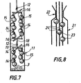
- Figure 7 is shown a form of embodiment of the invention in which the obstacles 15, here of spherical shape, arranged inside the tube 11, are supported by cables made up of a succession separate elements 14, interconnected transversely, at their upper end and at their lower end, by spacers 16, preferably flexible.
- the successive sets of cables and spacers are combined by assembly means known in the art, by example, as shown, by portions of cables 18 and 13, hooked together by carabiner systems 12.
- the obstacles carried by the cables have an axis of symmetry which coincides with the axis of the cable.
- the tube 21 has at its upper part an inlet 22 of diameter internal lower than that of the tube, as shown in the FIG. 8, it may be advantageous for the obstacles 23, carried by the cables 24 closest to the wall internal of the tube 21, have their axis of symmetry offset in direction of this wall, relative to the axis of the cable associated.
- the reactor tube used for the test measures approximately 7 meters long and its diameter is 100 mm. This diameter is constant over the entire height of the tube.
- the density of the loading obtained with the device according to the invention is substantially identical to that obtained with the system using flexible strips arranged regularly around an axial cable, while the amount of fines formed (which also includes any broken of catalyst grains) is about 1.5 times lower than that obtained with the lamella loading system.
- the device according to the invention allows, by elsewhere, to obtain superior loading qualities to the method of loading the bulk catalyst to from the upper end of the tube, with a density improved loading and a quantity of fines formed at course of this loading about 3 to 4 times less than that resulting from a bulk load.
Landscapes
- Chemical & Material Sciences (AREA)
- Organic Chemistry (AREA)
- Chemical Kinetics & Catalysis (AREA)
- Engineering & Computer Science (AREA)
- Mechanical Engineering (AREA)
- Devices And Processes Conducted In The Presence Of Fluids And Solid Particles (AREA)
- Basic Packing Technique (AREA)
Description
- diamètre extérieur : 16 mm,
- longueur : 18 mm,
- diamètre intérieur : 6 mm.
- par effet de pluie, de façon connue en soi, pour obtenir un chargement le plus homogène possible, le catalyseur étant versé délicatement à partir de l'extrémité supérieure du tube ;
- avec un système d'amortissement de la chute des particules constitué de lamelles métalliques souples disposées régulièrement autour d'un câble disposé suivant l'axe du tube, ces lamelles étant régulièrement réparties dans l'espace intérieur du tube et disposées environ tous les 50 cm sur le câble suivant toute la hauteur du tube ;
- avec le dispositif conforme à l'invention constitué de 4 câbles supportant chacun 9 obstacles en forme de balles d'un diamètre de 40 mm, réalisées en un matériau du type butyl iso butylène ; les câbles mesurent 7,20 m et sont reliés les uns aux autres par des entretoises souples disposées environ tous les 1 m ; les obstacles sont répartis régulièrement sur la hauteur du tube et sont décalés d'un câble par rapport à l'autre, de manière à être disposés en quinconce dans le tube.

Claims (13)
- Procédé pour faciliter le remplissage d'un tube vertical (1) à l'aide d'un matériau solide à l'état particulaire, du type dans lequel les particules descendent par gravité dans le tube (1) en rencontrant sur leur trajet des obstacles (5) supportés par au moins un câble ou similaire suspendu verticalement dans le tube, ce procédé étant caractérisé en ce qu'au cours de leur chute dans le tube, les particules rencontrent au moins trois obstacles (5), qui sont au moins pour partie décalés latéralement par rapport à l'axe du tube, au moins deux de ces obstacles (5) étant disposés dans le tube à des niveaux différents, la plus grande dimension des obstacles (5), perpendiculairement à l'axe du câble associé, étant comprise entre 0,25 et 0,75 fois le diamètre du tube (1)et ces obstacles (5) occupant au moins 80 % de la section transversale du tube (1) et en ce que, à mesure que le tube (1) se remplit, le câble (4) est remonté vers la partie supérieure du tube.
- Procédé selon la revendication 1, caractérisé en ce que les obstacles (5) sont en un matériau souple, apte à amortir le choc des particules, qui présente un facteur d'amortissement supérieur à 0,15 et de préférence supérieur à 0,2, à la température ambiante et sous une fréquence de 31 Hz.
- Procédé selon l'une des revendications 1 et 2, caractérisé en ce que, à mesure que le tube (1) se remplit, les câbles (4) sont remontés sensiblement en synchronisation vers la partie supérieure du tube (1).
- Dispositif pour faciliter le remplissage d'un tube vertical (1) à l'aide d'un matériau solide à l'état particulaire, qui descend par gravité dans le tube (1), du type comprenant au moins un câble ou similaire suspendu verticalement dans le tube, ce dispositif étant caractérisé en ce qu'il comprend au moins trois obstacles (5), qui sont au moins pour partie décalés latéralement par rapport à l'axe du tube, au moins deux de ces obstacles (5) étant disposés dans le tube à des niveaux différents, la plus grande dimension des obstacles (5), perpendiculairement à l'axe de leur support associé, étant comprise entre 0,25 et 0,75 fois le diamètre du tube (1), ces obstacles (5) occupant au moins 80 % de la section transversale du tube, et un moyen de levage du câble (4) apte à le remonter vers la partie supérieure du tube (1) à mesure que celui-ci se remplit.
- Dispositif selon la revendication 4, caractérisé en ce que au moins deux câbles (14) sont reliés par au moins une entretoise (16).
- Dispositif selon l'une des revendications 4 et 5, caractérisé en ce que les obstacles (5) sont disposés sensiblement symétriquement par rapport à l'axe du tube.
- Dispositif selon l'une des revendications 4 à 6, caractérisé en ce que certains au moins des obstacles (5) ont une symétrie de révolution et en ce que leur axe de symétrie est confondu avec l'axe de leur support associé.
- Dispositif selon l'une des revendications 4 à 6, caractérisé en ce que certains au moins des obstacles (23) ont une symétrie de révolution et en ce que leur axe de symétrie est décalé par rapport au câble (4).
- Dispositif selon l'une des revendications 7 et 8, caractérisé en ce que les obstacles (5) ont une forme sphérique, hémisphérique, conique, tronconique ou cylindrique.
- Dispositif selon l'une des revendications 4 à 9, caractérisé en ce que les obstacles (5) sont en un matériau souple, présentant un facteur d'amortissement, à température ambiante et sous une fréquence de 31 Hz, supérieur à 0,15 et de préférence supérieur à 0,2.
- Dispositif selon la revendication 10, caractérisé en ce que les obstacles (5) sont en un élastomère ou en un matériau alvéolaire.
- Dispositif selon la revendication 11, caractérisé en ce que le matériau souple est un caoutchouc butyl isobutylène.
- Dispositif selon l'une des revendications 13 et 14, caractérisé en ce qu'il comporte des moyens pour remonter sensiblement en synchronisation les différents câbles (4) vers la partie supérieure du tube (1), à mesure que celui-ci se remplit.
Applications Claiming Priority (3)
| Application Number | Priority Date | Filing Date | Title |
|---|---|---|---|
| FR9900945A FR2789050B1 (fr) | 1999-01-28 | 1999-01-28 | Procede et dispositif pour faciliter le remplissage de tubes verticaux a l'aide d'un materiau particulaire |
| FR9900945 | 1999-01-28 | ||
| PCT/FR2000/000182 WO2000044488A1 (fr) | 1999-01-28 | 2000-01-27 | Procede et dispositif pour faciliter le remplissage de tubes verticaux a l'aide d'un materiau particulaire |
Publications (2)
| Publication Number | Publication Date |
|---|---|
| EP1152819A1 EP1152819A1 (fr) | 2001-11-14 |
| EP1152819B1 true EP1152819B1 (fr) | 2003-06-25 |
Family
ID=9541314
Family Applications (1)
| Application Number | Title | Priority Date | Filing Date |
|---|---|---|---|
| EP00900671A Expired - Lifetime EP1152819B1 (fr) | 1999-01-28 | 2000-01-27 | Procede et dispositif pour faciliter le remplissage de tubes verticaux a l'aide d'un materiau particulaire |
Country Status (6)
| Country | Link |
|---|---|
| EP (1) | EP1152819B1 (fr) |
| AT (1) | ATE243553T1 (fr) |
| AU (1) | AU3060300A (fr) |
| DE (1) | DE60003526T2 (fr) |
| FR (1) | FR2789050B1 (fr) |
| WO (1) | WO2000044488A1 (fr) |
Families Citing this family (10)
| Publication number | Priority date | Publication date | Assignee | Title |
|---|---|---|---|---|
| ES2222420T3 (es) | 2001-08-07 | 2005-02-01 | Haldor Topsoe A/S | Procedimiento y dispositivo de carga de un catalizador. |
| EP1626801B1 (fr) | 2003-04-24 | 2019-03-06 | Cat Tech International Ltd. | Procede et appareil de chargement de catalyseur |
| DE10337998A1 (de) | 2003-08-19 | 2005-03-17 | Basf Ag | Verfahren zum Befüllen eines vertikalen Rohres mit Katalysatorteilchen |
| EP1749568B1 (fr) * | 2005-07-28 | 2009-03-25 | Aldo Cota | Dispositif pour le chargement de matériaux en grain dans des tubes |
| US7712490B2 (en) | 2006-03-16 | 2010-05-11 | Clean Harbors Catalyst Technologies, Llc | Method and apparatus for loading catalyst |
| DE102011081196A1 (de) | 2011-08-18 | 2013-02-21 | Wacker Chemie Ag | Verfahren zur Verpackung von polykristallinem Silicium |
| FR2995284B1 (fr) * | 2012-09-07 | 2015-09-18 | Crealyst | Dispositif de remplissage de granules, par exemple de granules de catalyseur dans un recipient vertical allonge |
| FR2996785B1 (fr) * | 2012-10-17 | 2015-03-06 | IFP Energies Nouvelles | Systeme pneumatique de chargement dense de catalyseur dans des tubes a baionnette pour reacteur echangeur de vaporeformage avec tube d'amenee de gaz amovible |
| FR2996784B1 (fr) | 2012-10-17 | 2015-10-16 | IFP Energies Nouvelles | Systeme de chargement dense du catalyseur dans des tubes a baionnette pour reacteur echangeur de vaporeformage faisant appel a des ralentisseurs souples et amovibles |
| FR2996782B1 (fr) * | 2012-10-17 | 2015-10-16 | IFP Energies Nouvelles | Systeme de chargement dense du catalyseur dans des tubes a baionnette pour reacteur echangeur de vaporeformage faisant appel a des deflecteurs amovibles |
Family Cites Families (5)
| Publication number | Priority date | Publication date | Assignee | Title |
|---|---|---|---|---|
| US3562998A (en) * | 1968-09-17 | 1971-02-16 | Catalyst Services Inc | Method for filling vertical process vessels with particulate materials |
| US3608751A (en) * | 1970-03-06 | 1971-09-28 | Allied Chem | Device and method for loading of vertical catalyst tubes |
| FR2621447B1 (fr) * | 1987-10-13 | 1990-12-07 | Salanove Edouard | Ralentisseur de chute des graines de semence dans les silos de stockage |
| NO175579B1 (no) * | 1991-12-20 | 1994-11-03 | Unidense Technology Gmbh | Fremgangsmate og innretning for fylling av partikkelformet materiale i vertikale ror |
| FR2762590B1 (fr) * | 1997-04-24 | 1999-06-11 | Cogema | Dispositif statique maintenant l'homogeneite d'un melange de poudres soumis a un ecoulement gravitaire |
-
1999
- 1999-01-28 FR FR9900945A patent/FR2789050B1/fr not_active Expired - Fee Related
-
2000
- 2000-01-27 AU AU30603/00A patent/AU3060300A/en not_active Abandoned
- 2000-01-27 AT AT00900671T patent/ATE243553T1/de not_active IP Right Cessation
- 2000-01-27 DE DE60003526T patent/DE60003526T2/de not_active Expired - Fee Related
- 2000-01-27 EP EP00900671A patent/EP1152819B1/fr not_active Expired - Lifetime
- 2000-01-27 WO PCT/FR2000/000182 patent/WO2000044488A1/fr not_active Ceased
Also Published As
| Publication number | Publication date |
|---|---|
| DE60003526T2 (de) | 2004-04-29 |
| WO2000044488A1 (fr) | 2000-08-03 |
| FR2789050B1 (fr) | 2001-04-13 |
| EP1152819A1 (fr) | 2001-11-14 |
| FR2789050A1 (fr) | 2000-08-04 |
| ATE243553T1 (de) | 2003-07-15 |
| DE60003526D1 (de) | 2003-07-31 |
| AU3060300A (en) | 2000-08-18 |
Similar Documents
| Publication | Publication Date | Title |
|---|---|---|
| EP1939115B1 (fr) | Dispositif de chargement d'une enceinte avec des particules solides et procédé utilisant ce dispositif | |
| EP0007854B1 (fr) | Dispositif de répartition d'un solide divisé dans une enceinte | |
| CA2715915C (fr) | Dispositif de chargement de particules de catalyseur dans des tubes presentant une zone annulaire | |
| EP0803286B1 (fr) | Procédé et dispositif pour le chargement homogène de particules d'un catalyseur solide dans un réacteur tubulaire | |
| EP1152819A1 (fr) | Procede et dispositif pour faciliter le remplissage de tubes verticaux a l'aide d'un materiau particulaire | |
| FR2949755A1 (fr) | Dispositif de chargement dense d'un solide divise dans une enceinte | |
| EP0122925B1 (fr) | Dispositif clos a fluidisation potentielle pour le convoyage de materiaux pulverulents | |
| EP2370202B1 (fr) | Dispositif pour le chargement de particules solides dans une enceinte | |
| US7673660B2 (en) | Filling tubes with catalyst and/or other particulate | |
| EP0470142A1 (fr) | Appareillage pour le remplissage d'un recipient par un produit solide divise. | |
| EP2908932B1 (fr) | Système de chargement dense du catalyseur dans des tubes a baionnette pour réacteur échangeur de vaporeformage faisant appel a des elements helicoidaux amovibles | |
| EP2908931B1 (fr) | Systeme pneumatique de chargement dense de catalyseur dans des tubes a baionnette pour reacteur echangeur de vaporeformage | |
| EP1348648A1 (fr) | Toboggan hélicoidal de transfert et de stockage | |
| LU84623A1 (fr) | Trempe thermique du verre | |
| EP2908933B1 (fr) | Systeme de chargement dense du catalyseur dans des tubes a baionnette pour reacteur echangeur de vaporeformage | |
| EP1012077B1 (fr) | Dispositif statique maintenant l'homogeneite d'un melange de poudres soumis a un ecoulement gravitaire | |
| EP1348649B1 (fr) | Toboggan répartiteur pour enceinte de transfert et de stockage de produits fragiles | |
| CA2816938A1 (fr) | Dispositif allege de chargement de particules solides | |
| CH629158A5 (fr) | Dispositif de protection pour appareil de chargement de materiaux pulverulents ou granuleux. | |
| WO2009080978A2 (fr) | Dispositif pour le transport de particules, installation et procede pour le chargement d'une enceinte avec le dispositif | |
| EP3360407B1 (fr) | Grille pour nettoyeur de grains | |
| FR2566530A1 (fr) | Dispositif et procede d'echantillonnage et de recuperation de matieres solides empilees a l'etat particulaire | |
| EP2892810B1 (fr) | Dispositif de remplissage de granules, par exemple de granules de catalyseur, dans un recipient vertical allonge | |
| EP0760713A1 (fr) | Dispositif et procede de separation et de qualification de particules formant un produit granuleux |
Legal Events
| Date | Code | Title | Description |
|---|---|---|---|
| PUAI | Public reference made under article 153(3) epc to a published international application that has entered the european phase |
Free format text: ORIGINAL CODE: 0009012 |
|
| 17P | Request for examination filed |
Effective date: 20010730 |
|
| AK | Designated contracting states |
Kind code of ref document: A1 Designated state(s): AT BE CH CY DE DK ES FI FR GB GR IE IT LI LU MC NL PT SE |
|
| AX | Request for extension of the european patent |
Free format text: AL;LT;LV;MK;RO;SI |
|
| GRAH | Despatch of communication of intention to grant a patent |
Free format text: ORIGINAL CODE: EPIDOS IGRA |
|
| GRAH | Despatch of communication of intention to grant a patent |
Free format text: ORIGINAL CODE: EPIDOS IGRA |
|
| GRAA | (expected) grant |
Free format text: ORIGINAL CODE: 0009210 |
|
| RAP1 | Party data changed (applicant data changed or rights of an application transferred) |
Owner name: TOTALFINAELF FRANCE |
|
| AK | Designated contracting states |
Designated state(s): AT BE CH CY DE DK ES FI FR GB GR IE IT LI LU MC NL PT SE |
|
| PG25 | Lapsed in a contracting state [announced via postgrant information from national office to epo] |
Ref country code: CY Free format text: LAPSE BECAUSE OF FAILURE TO SUBMIT A TRANSLATION OF THE DESCRIPTION OR TO PAY THE FEE WITHIN THE PRESCRIBED TIME-LIMIT Effective date: 20030625 Ref country code: FI Free format text: LAPSE BECAUSE OF FAILURE TO SUBMIT A TRANSLATION OF THE DESCRIPTION OR TO PAY THE FEE WITHIN THE PRESCRIBED TIME-LIMIT Effective date: 20030625 Ref country code: AT Free format text: LAPSE BECAUSE OF FAILURE TO SUBMIT A TRANSLATION OF THE DESCRIPTION OR TO PAY THE FEE WITHIN THE PRESCRIBED TIME-LIMIT Effective date: 20030625 Ref country code: IE Free format text: LAPSE BECAUSE OF FAILURE TO SUBMIT A TRANSLATION OF THE DESCRIPTION OR TO PAY THE FEE WITHIN THE PRESCRIBED TIME-LIMIT Effective date: 20030625 |
|
| REG | Reference to a national code |
Ref country code: GB Ref legal event code: FG4D Free format text: NOT ENGLISH |
|
| REG | Reference to a national code |
Ref country code: CH Ref legal event code: EP |
|
| REG | Reference to a national code |
Ref country code: IE Ref legal event code: FG4D Free format text: FRENCH |
|
| REF | Corresponds to: |
Ref document number: 60003526 Country of ref document: DE Date of ref document: 20030731 Kind code of ref document: P |
|
| PG25 | Lapsed in a contracting state [announced via postgrant information from national office to epo] |
Ref country code: GR Free format text: LAPSE BECAUSE OF FAILURE TO SUBMIT A TRANSLATION OF THE DESCRIPTION OR TO PAY THE FEE WITHIN THE PRESCRIBED TIME-LIMIT Effective date: 20030925 Ref country code: PT Free format text: LAPSE BECAUSE OF FAILURE TO SUBMIT A TRANSLATION OF THE DESCRIPTION OR TO PAY THE FEE WITHIN THE PRESCRIBED TIME-LIMIT Effective date: 20030925 Ref country code: SE Free format text: LAPSE BECAUSE OF FAILURE TO SUBMIT A TRANSLATION OF THE DESCRIPTION OR TO PAY THE FEE WITHIN THE PRESCRIBED TIME-LIMIT Effective date: 20030925 Ref country code: DK Free format text: LAPSE BECAUSE OF FAILURE TO SUBMIT A TRANSLATION OF THE DESCRIPTION OR TO PAY THE FEE WITHIN THE PRESCRIBED TIME-LIMIT Effective date: 20030925 |
|
| GBT | Gb: translation of ep patent filed (gb section 77(6)(a)/1977) |
Effective date: 20031027 |
|
| LTIE | Lt: invalidation of european patent or patent extension |
Effective date: 20030625 |
|
| PG25 | Lapsed in a contracting state [announced via postgrant information from national office to epo] |
Ref country code: ES Free format text: LAPSE BECAUSE OF FAILURE TO SUBMIT A TRANSLATION OF THE DESCRIPTION OR TO PAY THE FEE WITHIN THE PRESCRIBED TIME-LIMIT Effective date: 20031222 |
|
| PG25 | Lapsed in a contracting state [announced via postgrant information from national office to epo] |
Ref country code: LI Free format text: LAPSE BECAUSE OF NON-PAYMENT OF DUE FEES Effective date: 20040131 Ref country code: MC Free format text: LAPSE BECAUSE OF NON-PAYMENT OF DUE FEES Effective date: 20040131 Ref country code: CH Free format text: LAPSE BECAUSE OF NON-PAYMENT OF DUE FEES Effective date: 20040131 |
|
| REG | Reference to a national code |
Ref country code: IE Ref legal event code: FD4D |
|
| PLBE | No opposition filed within time limit |
Free format text: ORIGINAL CODE: 0009261 |
|
| STAA | Information on the status of an ep patent application or granted ep patent |
Free format text: STATUS: NO OPPOSITION FILED WITHIN TIME LIMIT |
|
| 26N | No opposition filed |
Effective date: 20040326 |
|
| REG | Reference to a national code |
Ref country code: CH Ref legal event code: PL |
|
| PGFP | Annual fee paid to national office [announced via postgrant information from national office to epo] |
Ref country code: LU Payment date: 20090115 Year of fee payment: 10 |
|
| PGFP | Annual fee paid to national office [announced via postgrant information from national office to epo] |
Ref country code: NL Payment date: 20090114 Year of fee payment: 10 Ref country code: DE Payment date: 20090122 Year of fee payment: 10 |
|
| PGFP | Annual fee paid to national office [announced via postgrant information from national office to epo] |
Ref country code: GB Payment date: 20090122 Year of fee payment: 10 |
|
| PGFP | Annual fee paid to national office [announced via postgrant information from national office to epo] |
Ref country code: BE Payment date: 20090219 Year of fee payment: 10 |
|
| PGFP | Annual fee paid to national office [announced via postgrant information from national office to epo] |
Ref country code: IT Payment date: 20090128 Year of fee payment: 10 |
|
| REG | Reference to a national code |
Ref country code: FR Ref legal event code: CD |
|
| BERE | Be: lapsed |
Owner name: *TOTALFINAELF FRANCE Effective date: 20100131 |
|
| REG | Reference to a national code |
Ref country code: NL Ref legal event code: V1 Effective date: 20100801 |
|
| GBPC | Gb: european patent ceased through non-payment of renewal fee |
Effective date: 20100127 |
|
| PG25 | Lapsed in a contracting state [announced via postgrant information from national office to epo] |
Ref country code: NL Free format text: LAPSE BECAUSE OF NON-PAYMENT OF DUE FEES Effective date: 20100801 |
|
| PG25 | Lapsed in a contracting state [announced via postgrant information from national office to epo] |
Ref country code: DE Free format text: LAPSE BECAUSE OF NON-PAYMENT OF DUE FEES Effective date: 20100803 |
|
| PG25 | Lapsed in a contracting state [announced via postgrant information from national office to epo] |
Ref country code: GB Free format text: LAPSE BECAUSE OF NON-PAYMENT OF DUE FEES Effective date: 20100127 |
|
| PG25 | Lapsed in a contracting state [announced via postgrant information from national office to epo] |
Ref country code: BE Free format text: LAPSE BECAUSE OF NON-PAYMENT OF DUE FEES Effective date: 20100131 |
|
| PG25 | Lapsed in a contracting state [announced via postgrant information from national office to epo] |
Ref country code: IT Free format text: LAPSE BECAUSE OF NON-PAYMENT OF DUE FEES Effective date: 20100127 |
|
| PG25 | Lapsed in a contracting state [announced via postgrant information from national office to epo] |
Ref country code: LU Free format text: LAPSE BECAUSE OF NON-PAYMENT OF DUE FEES Effective date: 20100127 |
|
| PGFP | Annual fee paid to national office [announced via postgrant information from national office to epo] |
Ref country code: FR Payment date: 20130305 Year of fee payment: 14 |
|
| REG | Reference to a national code |
Ref country code: FR Ref legal event code: ST Effective date: 20140930 |
|
| PG25 | Lapsed in a contracting state [announced via postgrant information from national office to epo] |
Ref country code: FR Free format text: LAPSE BECAUSE OF NON-PAYMENT OF DUE FEES Effective date: 20140131 |