-
The invention relates to robots. More
particularly, the invention relates to robot end
effectors.
-
Semiconductor substrates or wafers are processed to
produce integrated circuits using a series of sequential
processes. These steps are performed using a plurality
of process chambers. An assemblage of process chambers
served by a wafer transport robot is known as a cluster
tool. Many of the sequential processes performed in
different ones of, or the same, process chambers are
often performed at a different temperature.
-
Typical robots for objects such as semiconductor
wafers are located in a transfer chamber immediately
outside one or more of these process chambers. In this
manner, they can transfer wafers between various process
chambers to perform sequential processes occurring in
different process chambers, metrology chambers, or load
locks. The temperature of a wafer can be altered
significantly by thermal conduction with the end
effector with which the wafer is being supported, and is
in physical contact.
-
The term "end effector" as used in this disclosure
is intended to describe different embodiments of end
effectors, robot blades, or any device connected to the
distal end of a robot arm that is configured to support
a substrate during positioning or transfer of the
substrate. When the end effector transfers a wafer
between a series of process chambers (at least one of
the process chambers are maintained at different
temperatures from the remainder of the process
chambers), the temperature of the end effector may be
effected by the temperature of a previous process in
which the end effector was inserted, or a wafer which
the end effector previously contacted. A wafer
positioned inside a process chamber may be lower,
higher, or approaching the local temperature inside the
process chamber. When the end effector contacts a
wafer, the temperature of the two elements tend to
approach each other, and may eventually equalize due to
a combination of thermal radiation and convection.
-
When the end effector contacts a wafer inside a
process chamber, the temperature of the end effector
often rises as a result of conduction. When the end
effector is then moved to a second chamber, it may take
a considerable amount of time before the temperature of
the end effector equilibrates to the temperature of the
second process chamber. Much of the time for
temperature equalization is due to the amount of latent
thermal energy stored in the end effector. Since the
end effector is able to store more thermal energy due to
the relative material and larger size of the end
effector compared to a typical semiconductor wafer, the
temperature of the end effector typically adjusts at a
slower rate than the wafer when the wafer is placed in
contact with the end effector. It is desired to limit
contact between a wafer and the end effector that vary
in temperature by too much since a temperature gradient
may be established across the wafer. The temperature
gradient may effect the quality of the process film
and/or the ability to perform a particular process. The
time for temperature equalization is increased if there
is a substantial temperature difference between the two
process chambers. This increased time for temperature
equalization reduces the potential throughput of objects
within the process chamber.
-
Therefore, a need exists in the art for a method
that increases throughput in cluster tools having
process chambers with widely varying temperature
gradients.
-
Many disadvantages associated with the prior art
are overcome with the present invention that uses a
robot having a first end effector element and a second
end effector element. The robot performs object
transfers of one or more objects between multiple
process chambers. In one embodiment, the robot performs
object transfers of a plurality of objects between a
first process chamber, a second process chamber, and a
third process chamber. The first process chamber
operates at a similar temperature as the second process
chamber. The third process chamber operates at a
significantly different temperature than either the
first process chamber or the second process chamber.
The robot performs all object transfers from the first
process chamber to the second process chamber using the
first end effector portion. The robot further performs
all object transfers from the second process chamber to
the third process chamber using a second end effector
portion. In one embodiment of an end effector, the
first end effector portion is positioned on a different
robot arm, or a different portion of the same robot art
from the second end effector portion. The first end
effector thus may be able to be inserted into a process
chamber separately from the second end effector portion.
-
In another embodiment, a combined end effector may
be formed with a first end effector portion rigidly
connected by an insulative member to a second end
effector portion. For example, the back side of the
first end effector portion is secured to the back side
of the second end effector portion by an insulative
material. The combined end effector is attached to a
robot arm by a flipper portion such that the either the
first end effector portion or the second end effector
portion can be moved into a position to support an
object. The combined end effector can be inserted into
a single process chamber. Since only one of the first
end effector portion or the second end effector portion
supports (and is in contact with) the object, only that
end effector portion transfers a considerable amount of
heat to the object via thermal conductivity.
-
The teachings of the present invention can be
readily understood by considering the following detailed
description in conjunction with the accompanying
drawings, in which:
- FIG. 1 shows a top cross-sectional diagram of one
embodiment of cluster tool comprising a plurality of
process chambers;
- FIG. 2 shows a top cross-sectional diagram of
another embodiment of a cluster tool having a robot with
a plurality of end effectors, each end effector is
configured to carry one object;
- FIG. 3 shows an expanded perspective view of the
robot shown in FIG. 2;
- FIG. 4 shows a flow chart of one embodiment of
method performed by the controller shown in FIGs. 1 or
2 in transferring an object between multiple ones of the
process chambers;
- FIG. 5 shows a partial cross-sectional view of a
portion of a temperature controllable end effector;
- FIG. 6 shows a top perspective view of an alternate
embodiment of end effector; and
- FIG. 7 shows a side cross-sectional view as taken
through section lines 7-7 of FIG. 6.
-
-
To facilitate understanding, identical reference
numerals have been used, where possible, to designate
identical elements that are common to the figures.
-
After considering the following description, those
skilled in the art will realize that the teachings of
the invention can be readily utilized in robotic
systems. A single robot is configured to manipulate a
plurality of end effectors. Each end effector
transports objects between only certain ones of the
process chambers.
1. Process Chamber Configuration
-
FIG. 2 shows a first embodiment of cluster tool 200
comprising three process chambers 202, 204, and 206 that
are interconnected by a transport chamber 208, a twin-dual
arm robot 210, and a load lock chamber 201. The
twin-dual arm robot 210 is shown in greater detail in
FIG. 3. Such arms for dual arm robots are made by such
companies as GENMARK AUTOMATION, INC.; EQUIPE; and ADEPT
TECHNOLOGY. An example of a cluster tool equipped to
process two objects through a progression of process
chambers simultaneously using such dual arm robots is
known by the registered trademark "PRODUCER", and is
manufactured by APPLIED MATERIALS, INC.
-
The individual process chambers 202, 204 and 206 in
FIG. 2 may operate in a similar manner as, and be
configured similarly to, process chambers 104, 106, 108,
and 110 in FIG. 1. Examples of processes performed in
such process chambers include, but are not limited to,
chemical vapor deposition (CVD), physical vapor
deposition (PVD), deposition, metal etching and
electroplating.
-
Process chambers 202, 204, and 206 each have a slit
valve 214 and process chambers 104, 106, 108, and 110
each have a slit value 117 configured to permit access
to the interior of the process chamber by a wafer
carried by an end effector. The outer periphery of the
transport chamber 208 is defined by enclosure 212.
Alternatively, one or more of the process chambers 202,
204, and 206 may be stand-alone units without an
interconnecting transport chamber. The embodiments
shown in FIGs. 1 and 2 include a controller 136 as will
be described below.
-
The twin-dual arm robot 210 depicted in the
embodiment shown in FIG. 2 will now be described, and
comprises a first dual robot linkage 301 and a second
dual robot linkage 303. The first dual robot linkage 301
comprises a robot hub 320, a plurality of extendable
robot links 322, 323 that are hinged at 350,
interconnected robot arms 324, 325, and a plurality of
end effectors 302, 306. The second dual robot linkage
303 comprises a robot hub 330, a plurality of robot
links 332, 333 that are hinged at 352, interconnected
robot arms 334, 335, and a plurality of end effectors
304, 308.
-
In FIG. 2, assume pairs of objects 128 are routed
by twin-dual arm robot 210 in a clockwise direction from
load lock 201, to process chamber 202, to process
chamber 204, to process chamber 206, and back to load
lock 201. Any other type of routing that that transmits
objects between the different process chambers may be
used while remaining within the intended scope of the
present invention.
-
Although two robot linkages 301 and 303 are shown
in FIG. 2, it is envisioned that the operation of the
cluster tool 200 could utilize only one robot linkage
301 (assume robot linkage 303 is removed). Assuming
that only one robot linkage is used, only one wafer
(instead of a pair of wafers) is transferred between
successive process chambers.
-
The embodiment of cluster tool 100 shown in FIG. 1
comprises, for example, four process chambers 104, 106,
108, 110, a transfer chamber 112, and a pair of load
lock chambers 120 and 122. Each process chamber 104,
106, 108, 110 is typically configured to provide a
different processing stage or phase on an object (e.g.
semiconductor wafer). Each process chamber 104, 106,
108 and 110 communicates with the transfer chamber 112
through a sealable slit valve 117. The slit valve 117
may be opened in a known manner to provide insertion of
a wafer carried by an end effector into the respective
process chamber 104, 106, 108, or 110. Though the
disclosure describes objects such as semiconductor
wafers being transferred within the process chamber, it
is envisioned that the present invention may be applied
to any type of substrate or object known in the art to
be transferred by robots.
2. Multiple Blade Robot Embodiment
-
To transfer wafers between multiple ones of the
process chambers 104, 106, 108, and 110, one embodiment
of robot 132 is located in the transfer chamber 112
shown in FIG. 1. The robot 132 is a dual blade robot,
and comprises a first robot link 170 and a second robot
link 172. The first robot link 170 supports and
displaces a first end effector 174 while the second
robot link 172 supports and displaces a second end
effector 176. End effectors 174, 176 that are located
at a distal end of respective robot links 170, 172 each
are configured to carry individual objects 128, such as
wafers or other semiconductor substrates. The robot
links 170 and 172 of the robot 132 are configured such
robot links 170, 172 may extend their respective end
effectors 174, 176 a desired distance from axis 182
along an extension line 180. The inclination of
extension line 180 may be changed (within the horizontal
plane) by rotation of robot hub 181 about a vertical
axis 182. The use of a dual (or multiple) end effectors
174, 176 by the robot 132 allows the controller 136 to
select one of a plurality of end effectors to transfer
objects between the plurality of process chambers 104,
106, 108, and 110.
-
Objects 128, (such as wafers) are typically loaded
in a cassette 126 that is located within one of the load
lock 120 or 122. The cassettes store a plurality of
objects in a vertically aligned configuration. The
cassettes may be displaced vertically so a desired one
of the stored objects contained in the cassette may be
aligned with the desired end effector 174, 176 to permit
loading of the desired object by the end effector.
Robot 124 transports objects 128 (e.g. wafers) one at a
time from the cassette 126 in load lock 120 or 122 to
any of the process chambers 104, 106, 108, or 110.
Individual wafers that are to be processed in the
cluster tool are carried by end effectors 174, 176
mounted to and displaced by the robot 132. The end
effectors displace the wafers between different ones of
the process chambers in series, depending upon the
specific desired processing to be performed upon the
object. The end effectors 174, 176 are located at the
distal end of the first robotic mechanism 124 in a
position to provide for transfer, lifting, retraction,
and or extension of the object.
-
The processing of objects such as semiconductor
wafers often requires that one object (or a pair of
objects in the embodiment shown in FIG. 2) be
transferred through a succession of many process
chambers. Process chambers 104, 106, 108 and 110 are
configured to perform a variety of processes such as
physical vapor deposition (PVD), chemical vapor
deposition (CVD), electroplating, etching, or metal
deposition processes, etc. The robots 124, 132 can most
conveniently perform these sequential steps when the
multiple process chambers are positioned physically
close to each other. Process chambers 104, 106, 108,
110 typically operate at different temperatures to
perform varied processes'. Typically the object is
maintained at the desired temperature by conditioning
the temperature of the individual process chamber.
-
One embodiment of the invention involves the use of
dual arm robots for temperature sensitive applications
such as spin-on dielectrics, this embodiment is now
described. This embodiment may be applied to either the
cluster tool 100 of FIG. 1, the cluster tool 200 of FIG.
2, or any known assembly of independent process chambers
or cluster tools. It is important that the temperature
of an object be maintained at a steady value for certain
processes. Thus, the temperature of the end effector
should approximate the temperature of an object (such as
wafer) during processing in the process chamber 202.
Achieving this temperature equality between the object
and the end effector in cluster tools 100 and 200 relies
upon maintaining the end effector temperature at
approximately the temperature of process chamber 202.
-
If the end effector is moved between different
process chambers 104, 106, 108, and 110 operating at
different temperatures then it is difficult to maintain
the end effector at the appropriate temperature of the
process chambers that the end effectors are being moved
into without affecting throughput. Also, if the
temperature of the end effector differs from the
temperature of the object it is contacting, it is
difficult to maintain the temperature of the object
because thermal energy in the object will transfer by
conduction to the end effector. If the object is
transferring heat via conduction, a thermal gradient may
be established across the object. If the object
temperature differs significantly from the desired
temperature in a temperature-sensitive application, then
the quality of the processing of the object (e.g. film
deposited on the wafer) will likely be affected. If a
thermal gradient is established across the object in
temperature sensitive applications, then the quality of
the process also may not be consistent. To limit the
variation of temperature between the end effectors and
the process chamber in which the end effector is being
inserted, the embodiments shown in FIGs . 1 and 2 use one
or more end effectors to transfer objects between a
first set of chambers and another one or more end
effectors to transfer objects between another set of
chambers. These techniques that limit temperature
variation of the end effectors are especially desirable
where the temperature of an object is critical to the
resulting quality of the object being processed.
-
The above provides a general outline of a design of
two embodiments of cluster tools 100, 200. It is
envisioned that the present invention may be applied to
other embodiments of cluster tools, or even entirely
different systems that are operated at different
temperatures and/or pressures.
-
For an example of the use of one embodiment of the
present invention shown in FIG. 2, consider the
temperature of process chamber 206 to be different, and
higher, than the temperature of process chambers 202 and
204. The teachings of the present invention may also
apply if the process chamber 206 has a lower temperature
than the process chambers 202 and 204. During
processing within cluster tool 200, pairs of objects 128
are considered to be moved from load lock 201, to
process chamber 202, to process chamber 204, to process
chamber 206, and finally to the load lock 201 once
again. This sequence is then repeated with new
unprocessed objects. Different sequences between the
different process chambers may be used, but the above
illustrative sequence provides an illustrative
embodiment that can be applied to a wide variety of
cluster tools and/or stand-alone units.
-
If a pair of end effectors of the robot transfers
objects between different process chambers that are
operating at different temperatures, and the wafer is
temperature sensitive, the robot has to pause inside of
the process chamber before picking up an object from
process chamber (to achieve the desired temperature by
convection). For example, suppose the same end effector
transferred a first pair of objects to process chamber
202. The pair of objects are then transferred to
process chamber 204, and then to process chamber 206.
The pair of objects in process chamber 206 are then
transferred to load lock 201. A second pair of objects
are then transferred from process chamber 202 to process
chamber 204. Assume that process chamber 206 is
maintained at a higher temperature than process chambers
202 or 204. During the above wafer transfer
progression, the same end effector that transfers wafers
to and from a warmer process chamber (206) are then used
to transfer another wafer to a cooler process chamber
(202). The temperature of the end effectors (that are
used to transfer the object) will therefore likely have
a higher temperature than the process chamber 202. A
pause in process chamber 202 may thus be necessary to
permit the temperature of the end effector to approach
the temperature of the process chamber before the wafer
can be picked up. Otherwise, the temperature of an
object will be changed and a thermal gradient will
establish across the object as thermal energy contained
in the end effector is conducted between an object and
the end effector. Pauses of this type reduce the
throughput of the cluster tool considerably.
-
To avoid this problem, the twin-dual arm robot 210
shown in FIG. 3 can be equipped with a total of four end
effectors. Two end effectors 302 and 304 handle a pair
of wafers simultaneously, and two other end effectors
306 and 308 handle another pair of objects
simultaneously. End effectors 302 and 304 are used only
to transfer wafers from process chambers where the
temperatures are close to each other. For example, the
robot 210 (under the control of the controller 136) uses
only one pair of end effectors 302 and 304 to transfer
objects 128 between process chamber 202 and process
chamber 204. By comparison, the robot 210 (under the
control of the controller 136) uses another pair of end
effectors 306 and 308 to transfer objects between all
other chambers that are operating at a different (e.g.
higher) temperature, primarily between process chamber
204 to process chamber 206. The temperatures of the end
effectors 302 and 304 do not have to be lowered
significantly to reach the processing temperature for
process chamber 202 and 204 since the end effectors 302
and 304 are not being inserted into process chamber 206.
The time in which the end effector is maintained in
process chamber 202 to lower the temperature is
therefore reduced. This limiting of the time that the
end effector is to be held in the process chamber
increases the maximum throughput of objects 128 through
the cluster tool 200.
-
While the above describes the interaction between
process chambers and robots having a twin-dual arm
within cluster tools in general, it is envisioned that
an embodiment of the present invention may applied to
either single dual arm robot. For example, the
embodiments shown in FIG. 3 may be adapted as having
only one dual robot linkage 301. The operation of the
dual robot linkage 301 remains as described.
-
A controller 136, shown in FIGs. 1 and 2, controls
the operation of the cluster tools 100 and 200
respectively, and the associated operation of the robot
as described. The conductor 136 contains a
microprocessor 138 (CPU), a memory 140 for storing the
control routines, and support circuits 142, such as
power supplies, clock circuits, cache and the like.
Controller 136 also contains input/output peripherals
144 such as a keyboard, mouse, and display. The
controller 136 is a general-purpose computer that is
programmed to perform the sequencing and scheduling
operations that facilitate processing and transport of
the objects. The software routines that control the
cluster tool are stored in memory 140 and are executed
by microprocessor 138 to facilitate control of the
cluster tool 200.
-
It is contemplated that some of the process steps
discussed herein as software processes may be
implemented within hardware, e.g., as circuitry that
cooperate with the microprocessor to perform various
process steps. Although the controller 136 is depicted
as a general purpose computer that is programmed to
perform various scheduling routines, the processes that
are implemented by the software can be implemented as
hardware as an application specific integrated circuit
(ASIC) or as discrete circuit components. As such, the
process steps described herein should be broadly
interpreted as being equivalently performed by software,
hardware, or any combination thereof.
-
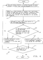
One embodiment of a method 400 performed by
controller 136 that controls robot motion by determining
which end effectors to be used to transfer objects
between certain process chambers is depicted in FIG. 4.
Controller 136 controls the processing necessary to
transfer objects between multiple process chambers in
the cluster tool 100 or 200, including the operation of
the robots 124, 132 (shown in FIG. 1), and 210 (shown in
FIG. 2). The controller 136 begins method 400 at step
402 by considering the total routing of the wafers
between multiple process chambers in which either a
first end effector or a second end effector can
transport the different objects. In FIG. 1, for
example, robot 132 having multiple end effectors 174,
176 might transfer an object between any ones of
multiple process chambers 104, 106, 108, and 110. By
comparison, in the FIG. 2 embodiment, the twin-dual arm
robot 210 comprising end effectors 302, 304, 306, and
308, may transfer pairs of objects between the process
chambers 202, 204, 206. As such, the total permutations
of routing between the different process chambers 104,
106, 108, and 110 by robot 124, 133, or 210 may be
considered as the "total routing" of the objects.
-
Method 400 continues to step 404 in which the
controller 136 breaks down the total routing of objects
into plurality of individual routes in which a pair of
(or a single) wafer is transferred between two process
chambers. The plurality of routes comprises those first
routes to be performed by the first end effector, and
all other "second" routes to be performed by the second
end effector. The first end effector is limited to
transferring an object or objects between those process
chambers that are at approximately the same temperature.
For example, assume in FIG. 1 that process chambers 104
and 106 operate at nearly the same process chamber 104
and process chamber 106 are at the same temperature,
while process chambers 108 and 110 each operate at
somewhat different temperatures then the process
chambers 104 and 106.
-
The first end effector (which we assume to be 176),
is provided to transfer all wafers between process
chamber 104 to 106, but it is not inserted into process
chambers 108 or 110 that are at different temperatures.
Therefore, the temperature of the first end effector
should be maintained at approximately the temperature of
process chamber 104 and 106.
-
This maintaining the temperature of the end
effector can be enhanced by using the embodiment of end
effector 500 shown in FIG. 5. The end effector 500
includes a first plate 502, a second plate 504, end
plates 505, side plates (not numbered) a honeycomb
structure 506, a fluid inlet 508, and a fluid outlet
510. The honeycomb structure is formed from individual
honeycombs 512 that are constructed from metal. The
honeycombs are typically configured in a closed
geometric shape such as triangles, rectangles, or
pentagons, although any closed geometric shape may be
used for honeycombs. Only a few honeycomb structures
are depicted in the embodiment shown in FIG. 5, wherein
many more honeycomb structures would typically be
provided in such an end effector to enhance the
structural strength of the end effector. The honeycomb
structures are to be sufficiently spaced to enable the
fluid passing into the end effector 500 from the fluid
inlet 508 to pass through the interior of substantially
all of the end effector 500, and then exit via the fluid
outlet 510. The flow rate into the end effector 500
through fluid inlet 508 equals the fluid flow rate out
of fluid outlet 510, and must be sufficient to transfer
the excess heat. The closed geometric shape of each
honeycomb surrounds an interior portion 514, and each
honeycomb is surrounded by an exterior void 516.
-
During operation, a heat transfer fluid is injected
into the exterior void 516 through the fluid inlet 508,
and the heat transfer fluid circulates through the
exterior void 516 to transfer the heat applied to the
end effector 500. The heat transfer fluid present in
the exterior void exits through the fluid outlet 510,
and circulates to a heat transfer device (not shown).
The heat transfer device is preferably a heat transfer
element that maintains the temperature of the heat
transfer fluid to a desired temperature (by sinking the
excessive heat) before returning it into the fluid inlet
508. The fluid outlet 510, heat exchanger, fluid inlet
508, the exterior void 516 in the end effector, and the
various connectors extending between these elements
define a closed loop within which the temperature
maintaining fluid continually circulates.
-
As soon as end effector 500 moves an object from
process chamber 104 to process chamber 106, it can
insert another object in process chamber 104 without
changing the temperature of that object. As such,
processing can begin within process chamber 104 soon
after the robot inserts another object having a suitable
temperature therein.
-
All transfer of objects between process chamber 106
and 108 or between process chambers 108 and 110 (that
are maintained at elevated temperatures) is to be
accomplished by the second and effector 174. The second
end effector can quickly enter process chambers 104 or
106 (after being contained in process chambers 108 or
110) without waiting for thermal equalization since the
end effector is closer to the temperature of the process
chamber that the object is to be processed in, and not
the temperature of the process chamber that the object
is being removed from. As such, the use of first end
effector 176 increases the overall throughput where
compared to transferring each object through all process
chambers with a single end effector. The use of the
second end effector 176 may not effect the overall
throughput when compared to transferring each object
through all process chambers with a single end effector.
-
After step 404 of method 400 is completed, the
controller 136 continues to step 406 in which it
determines those individual routes to be performed
imminently. These are those routes, comprising either
first routes or second routes of step 404, that the
robot is in a position to perform at the present time.
The individual routes to be performed imminently, as
with all other individual routes, are considered as
being made up of transfer of objects between two process
chambers (or alternatively) between a process chamber
and a load lock.
-
The method 400 then continues to decision step 408
in which the controller 136 considers whether the first
route to be performed by the first end effector. If the
answer to decision step 408 is "YES", then the method
continues to step 410 in which the controller 136
authorizes progressing using the first end effector.
Controller 136 causes the robot 132 or 210 to move end
effector 174, 176, or alternatively two pairs of end
effectors 306, 308 or 302, 304 to perform the routes.
A first pair of end effectors 302, 304 will transfer
objects between chambers having approximately the same
temperature.
-
If the answer to decision step 408 is "NO", then
the controller 136 authorizes the second end effector
(or second pair of end effectors 306, 308) to transfer
the objects(s). Controller 136 will then cause robot
132 or 210 to move end effector 174 or 176, or
alternatively a pair of end effectors 306 and 308, or
302 and 304, to perform the routes using the second end
effectors and which will transfer wafers between process
chambers having different temperatures. The presumption
in the operation of the controller 136 is that
maintaining the temperature of the second end effector
is not as important for increasing the throughput of the
corresponding processes as maintaining the temperature
of the first end effector(s).
-
During typical processing, an end effector can be
positioned in a heated process chamber, and the
temperature of the end effector will typically be
maintained at approximately the temperature that it was
when it entered the process chamber since the amount of
time the end effector is in the process chamber is
relatively brief. For example, during typical
processing, an end effector may be in a process chamber
for several seconds to drop off or pick up a wafer. The
amount of time that the end effector is positioned
outside of any one process chamber is typically much
larger compared with the amount of time that the end
effector is contained within the process chamber. It is
actually often repeated insertions of an end effector in
one specific process chamber that can significantly
affect the temperature of the end effector.
-
The controller 136 may base its determination of
temperature of the different process chambers either
upon general known operation of the cluster tool of by
quantitative measurements. An example of general
operation is that the controller 136 may assume that
process chambers 104 and 106 generally operate at
similar temperatures while process chambers 108 and 110
generally operate at higher temperatures. Certain end
effectors may be used for routes between different
process chambers accordingly. The specifics of the
general operation of the controller are input by the
user of the controller based upon knowledge of the
operation of the specific cluster tool and its process
chambers.
-
By comparison, an example of quantitative
measurement as applied to the controller 136 utilized in
the embodiments shown in FIGs. 1 and 2 might be actual
temperature measurements within process chambers 202 and
204 as measured at a specific time during operation of
the cluster tool. The quantitative measurements may be
used to determine, for example, which end effectors can
be used between different ones of the process chambers.
The use of certain end effectors to transfer objects
between certain ones of the process chambers may be
applied accordingly.
-
After either step 410 and step 412 is performed,
the process continues to decision step 414 in which the
controller 136 considers whether all routing to be
performed by the robot has been completed. If the
answer to decision step 414 is NO, then the controller
136 returns to step 402 to loop through the method once
again. During the subsequent looping through method
400, different routes will be determined to be the
routes that are to be performed imminently. In this
manner a continual progression of objects will be
maintained through the different process chambers. If
the answer to step 414 is "YES", then the controller 136
halts method 400. Method 400 is preferably performed at
intervals (e.g. every 30 seconds). The controller 136
will properly handle the routing if any routes have to
be performed imminently.
-
It is noted that while all routes in FIGs. 1 and 2,
relative to FIG. 4, have been shown in the general
clockwise directions, there is no reason that any
combination between different process chambers, other
chambers, and load locks, can be considered as routing.
For example, while the first route in method 400 is
described as being those routes from process chamber 104
to 106 (since process chambers 104 and 106 are at
similar temperatures) the route from process chamber 106
to 104 is also to be considered a first route. Any
route performed between process chambers having
temperatures within the range of the temperature-sensitive
application may be considered as a first
route.
3. Single Blade Robot Embodiment
-
Another embodiment of end effector 600 that
contains a plurality of end effector portions, each end
effector portion may be used to transfer objects between
different process chambers is shown in FIGs. 6 and 7.
In this embodiment, a single end effector element
comprises a first end effector portion 602 and a second
end effector portion 604. End effector portion 602 is
used to transfer objects between one set of process
chambers, while the end effector 600 can be flipped
about an axis to permit end effector portion 604 to be
is used to transfer objects between another set of
process chambers.
-
When considering the end effector 600, FIGs. 6 and
7 should be viewed in combination. The end effector
comprises a first end effector portion formed as outer
layer 602, a second end effector portion formed as outer
layer 604, an insulative layer 606, and a flipper
element 608. The first end effector portion 602 and the
second end effector portion 604 is preferably formed
from an aluminum, a stainless steel, a composite, or
some other material depending largely upon the chemicals
that are applied to the process chamber in which the end
effector 600 will be inserted. The end effector
portions 602, 604 are each configured, and have the
general shape, as a single end effector described above.
The end effector portions 602 and 604 are positioned in
a back-to-back orientation such that the sides of the
end effector portions 602, 604 that are configured to
support an object (such as a wafer 620) face opposite
directions. In this orientation, when the first end
effector portion 602 is facing upwardly the second end
effector portion 604 is facing downward, and vice versa.
The flipper element 608 acts to flip the end effector
600 between the end effector portion 602 or 604 that is
in a position to support the object 620 (for example the
other end effector portion may be inverted and incapable
of supporting the object). While it is most common in
semiconductor processing that the robot supports an
object from below, it is to be understood that there are
those applications that the end effector supports the
top of the object 620 by vacuum chucking (for example in
electroplating, not shown), or even that the object 620
may be supported by the end effector in a sideways
position.
-
The end effector 600 positions only one object at
a time in a process chamber. Assume that the first end
effector portion 602 that is facing up is the one that
is in contact with, and supporting, the wafer. The
assignment of the first end effector portion 602 and the
second end effector portion 604 is arbitrary since both
end effector portions are configured similarly and
perform similar operations. The end effector portion
602 or 604 that is oriented in a particular direction
may also be switched by actuating the flipper element
608.
-
The object will not be contacting the second end
effector portion 604 that is directed downwardly in the
embodiment shown in FIG. 6 when being supported by the
end effector in the orientation shown in FIGs. 6 and 7.
Heat is therefore not being transmitted between the
second end effector portion 604 and the wafer 620 by
thermal conduction. Any heat loss of the end effector
portion that is not contacting the wafer is though
thermal convection. It typically requires a
considerably longer time to transfer thermal energy
contained in an end effector 602 or 604 through thermal
convection than thermal conduction, so the temperature
variation to the second end effector portion 604 when
inserted into a process chamber for several seconds
before removal therefrom, is not significant.
-
Although various embodiments that incorporate the
teachings of the present invention have been shown and
described in detail herein, those skilled in the art can
readily devise many other varied embodiments that still
incorporate these teachings.