EP1152193A1 - Ceiling-embedded type air conditioner - Google Patents
Ceiling-embedded type air conditioner Download PDFInfo
- Publication number
- EP1152193A1 EP1152193A1 EP00955017A EP00955017A EP1152193A1 EP 1152193 A1 EP1152193 A1 EP 1152193A1 EP 00955017 A EP00955017 A EP 00955017A EP 00955017 A EP00955017 A EP 00955017A EP 1152193 A1 EP1152193 A1 EP 1152193A1
- Authority
- EP
- European Patent Office
- Prior art keywords
- ceiling
- air
- horizontal vane
- straightening
- air conditioner
- Prior art date
- Legal status (The legal status is an assumption and is not a legal conclusion. Google has not performed a legal analysis and makes no representation as to the accuracy of the status listed.)
- Withdrawn
Links
Images


Classifications
-
- F—MECHANICAL ENGINEERING; LIGHTING; HEATING; WEAPONS; BLASTING
- F24—HEATING; RANGES; VENTILATING
- F24F—AIR-CONDITIONING; AIR-HUMIDIFICATION; VENTILATION; USE OF AIR CURRENTS FOR SCREENING
- F24F1/00—Room units for air-conditioning, e.g. separate or self-contained units or units receiving primary air from a central station
- F24F1/0007—Indoor units, e.g. fan coil units
- F24F1/0011—Indoor units, e.g. fan coil units characterised by air outlets
-
- F—MECHANICAL ENGINEERING; LIGHTING; HEATING; WEAPONS; BLASTING
- F24—HEATING; RANGES; VENTILATING
- F24F—AIR-CONDITIONING; AIR-HUMIDIFICATION; VENTILATION; USE OF AIR CURRENTS FOR SCREENING
- F24F1/00—Room units for air-conditioning, e.g. separate or self-contained units or units receiving primary air from a central station
- F24F1/0007—Indoor units, e.g. fan coil units
- F24F1/0043—Indoor units, e.g. fan coil units characterised by mounting arrangements
- F24F1/0047—Indoor units, e.g. fan coil units characterised by mounting arrangements mounted in the ceiling or at the ceiling
-
- F—MECHANICAL ENGINEERING; LIGHTING; HEATING; WEAPONS; BLASTING
- F24—HEATING; RANGES; VENTILATING
- F24F—AIR-CONDITIONING; AIR-HUMIDIFICATION; VENTILATION; USE OF AIR CURRENTS FOR SCREENING
- F24F13/00—Details common to, or for air-conditioning, air-humidification, ventilation or use of air currents for screening
- F24F13/08—Air-flow control members, e.g. louvres, grilles, flaps or guide plates
- F24F13/10—Air-flow control members, e.g. louvres, grilles, flaps or guide plates movable, e.g. dampers
- F24F13/14—Air-flow control members, e.g. louvres, grilles, flaps or guide plates movable, e.g. dampers built up of tilting members, e.g. louvre
-
- F—MECHANICAL ENGINEERING; LIGHTING; HEATING; WEAPONS; BLASTING
- F24—HEATING; RANGES; VENTILATING
- F24F—AIR-CONDITIONING; AIR-HUMIDIFICATION; VENTILATION; USE OF AIR CURRENTS FOR SCREENING
- F24F13/00—Details common to, or for air-conditioning, air-humidification, ventilation or use of air currents for screening
- F24F13/02—Ducting arrangements
- F24F13/06—Outlets for directing or distributing air into rooms or spaces, e.g. ceiling air diffuser
- F24F2013/0616—Outlets that have intake openings
-
- F—MECHANICAL ENGINEERING; LIGHTING; HEATING; WEAPONS; BLASTING
- F24—HEATING; RANGES; VENTILATING
- F24F—AIR-CONDITIONING; AIR-HUMIDIFICATION; VENTILATION; USE OF AIR CURRENTS FOR SCREENING
- F24F13/00—Details common to, or for air-conditioning, air-humidification, ventilation or use of air currents for screening
- F24F13/08—Air-flow control members, e.g. louvres, grilles, flaps or guide plates
- F24F13/082—Grilles, registers or guards
- F24F2013/088—Air-flow straightener
Definitions
- This invention relates to an arrangement and structure of an air outlet of a ceiling-embedded type air conditioner, and particularly relates to the field of an anti-contamination technique for controlling the supply direction of a conditioned air, for example, during cooling operation to prevent particulate dust contained in the conditioned air from adhering to a ceiling surface.
- a conventional ceiling-embedded type air conditioner is provided at its air outlet with a horizontal vane capable of up and down change in the supply direction of a conditioned air.
- the horizontal vane makes the supply direction of the conditioned air relatively downward during heating operation and makes it relatively upward during cooling operation so that the supplied airflow will be approximately parallel to the ceiling surface (a so-called horizontal air supply), thereby uniformizing the temperature profile in a room in each operation mode for enhancement in air conditioning efficiency.
- the airflow supplied in the horizontal air supply condition through the air outlet ( a ) is substantially in V form as viewed along the airflow. Since the initial rate of air supply is higher at a longitudinally middle portion of the air outlet ( a ), the airflow at that portion will pass through a region away from the ceiling surface ( b ). Further, since particulate dust contained in such a supply air has a high inertia force; such dust seldom adheres to the ceiling surface ( b ).
- Japanese Unexamined Patent Publication 3-160266 has proposed that the horizontal vane is provided with a detachable auxiliary fin for shifting the air supply direction toward the ceiling surface and the auxiliary fin is attached or detached depending upon ease of production of contamination at the ceiling.
- the auxiliary fin may be detached to orient the horizontal vane downwards under environments where the room air contains much dust to readily produce contamination of the ceiling or at locations such as hospitals where demands for anti-contamination are particularly great, whereas the auxiliary fin may be attached to allow a horizontal air supply under environments where contamination of the ceiling may be hard to occur or at locations where demands for anti-contamination are small.
- the present invention has been made in view of the above points and therefore has its object of preventing contamination of the ceiling surface while obtaining a suitable air supply direction in accordance with each operation mode of the air conditioner by exercising ingenuity on the design of the air outlet for the conditioned air.
- the present invention takes the following measures to solve the above problems.
- a first invention is directed to a ceiling-embedded type air conditioner (1) embedded in a ceiling surface (70) and provided with a laterally elongated air outlet (16) for supplying a conditioned air therethrough toward a room space and with a guide means ( 18 ) that is located in the air outlet (16) and has the ability to guide a supply of the conditioned air so that a supply direction of the conditioned air forms substantially 45° or less with respect to the ceiling surface (70).
- the air outlet (16) is provided at least substantially at both longitudinal ends thereof with straightening members (19) for straightening the flow of the conditioned air into a two-dimensional flow along a vertical plane.
- the guide means (18) is preferably adapted to curve an air passage upstream of the air outlet (16) so that the direction of the conditioned air to be supplied makes substantially 45 ° or less with the ceiling surface ( 70 ).
- the conditioned air supplied through the air outlet (16) of the air conditioner (1) during cooling operation is guided by the guiding means (18) to form a jet blown out toward the room space at 45° or less with respect to the ceiling surface (70).
- the axis of the jet is turned toward the ceiling surface (70) due to Coanda effect.
- the straightening members (19) are disposed at least substantially at both longitudinal ends of the air outlet (16), respectively, and straightens the flows of the conditioned air at both lateral side portions of the air outlet into two-dimensional flows along the vertical plane, the initial rate of supply of the conditioned air becomes as high also at both the lateral side portions as at the middle portion of the air outlet.
- the airflows will not reach the ceiling surface (70) but will gradually go down in the course of time due to a temperature difference from the room air. Accordingly, even if the supply direction of the conditioned air is made upward so that the airflow will be approximately parallel to the ceiling surface, the airflow can be suppressed from traveling along the ceiling surface, thereby preventing contamination of the ceiling surface in a so-called horizontal air supply condition.
- the guide means (18) comprises a horizontal vane that allows up and down change in the supply direction of the conditioned air and straightening plates as the straightening members (19) are disposed on the horizontal vane (18).
- an extension height ( ⁇ h) at which the straightening plate (19) extends from the horizontal vane (18) is 5mm or more and 30 mm or less (a third invention).
- the extension height ( ⁇ h) is 22.5 mm (a fourth invention).
- the flow direction of the conditioned air from the air outlet (16) can be changed up and down by the horizontal vane (18)
- the flow of the supply air can be oriented relatively downward during heating operation, while it can be put into a horizontal air supply condition during cooling operation.
- the air conditioning efficiency can be thereby enhanced in each operation mode.
- the flow of the supply air can be effectively straightened by the straightening plates (19) provided on the horizontal vane ( 18 ).
- the horizontal vane (18) is formed of an elongated plate member that curves over the width thereof and the plurality of straightening plates (19) are fixedly arranged on an inner curved surface of the horizontal vane (18) at a predetermined pitch over the entire length in a longitudinal direction of the horizontal vane (18).
- the pitch ( ⁇ p) of the straightening plates (19) in respect of the longitudinal direction of the horizontal vane (18) is 10 mm or more and 60 mm or less (a sixth invention).
- the pitch ( ⁇ p) of the straightening plates (19) is 50 mm (a seventh invention).
- the number of the straightening plates (19) to be arranged on each single horizontal vane (18) is 10 (an eighth invention).
- the widthwise curved, elongated horizontal vane (18) can smoothly change the flow of the conditioned air to change the supply direction thereof. Further, since the straightening plates are fixedly arranged on the inner curved surface of the horizontal vane (18) over the entire length thereof, the flow of the supply air can entirely be straightened by these straightening plates.
- the guide means (18) comprises a horizontal vane that allows up and down change in the supply direction of the conditioned air and straightening plates as the straightening members (19) are disposed on an inclined surface (16b) opposed to a front face of the horizontal vane in an air passage connecting to the air outlet (16) .
- a tenth invention is directed to a ceiling-embedded type air conditioner (1) embedded in a ceiling surface (70) and provided with a laterally elongated air outlet (16) for supplying a conditioned air therethrough toward a room space and with a horizontal vane (18) that is located in the air outlet (16) and has the ability to guide a supply of the conditioned air.
- the horizontal vane (18) is formed of an elongated plate member that curves over the width thereof, a plurality of straightening plates (19) are fixedly arranged on an inner curved surface of the horizontal vane (18) over the entire length thereof, and each of the straightening plates (19) is disposed to be substantially orthogonal to the inner surface of the horizontal vane (18) and extend over the width thereof.
- the flow direction of the conditioned air from the air outlet (16) of the air conditioner (1) can be changed up and down by the horizontal vane (18). Therefore, if the flow of the supply air is relatively downward during heating operation while it is put into a horizontal air supply condition during cooling operation, the air conditioning efficiency can be enhanced in each operation mode. Further, the widthwise curved, elongated horizontal vane (18) can smoothly change the flow of the conditioned air.
- the straightening plates (19) fixedly arranged on the inner curved surface of the horizontal vane (18) can straighten the flow of the supply air so that the entire flow thereof including partial flows at both the lateral sides of the air outlet (16) can be formed into a two-dimensional flow along the vertical plane.
- the partial airflows at both the lateral sides of the air outlet (16) also increase in the initial rate of supply of the conditioned air like the partial airflow at the middle of the air outlet (16). Accordingly, even in a so-called horizontal air supply condition during for example the cooling operation, it can be suppressed that the flow of the conditioned air travels along the ceiling surface (70), which can prevent contamination of the ceiling surface.
- the air outlet (16) is provided at least substantially at both longitudinal ends thereof with straightening members (19) for straightening the flow of the conditioned air into a two-dimensional flow along the vertical plane.
- the supply direction of the conditioned air can be changed up and down by the horizontal vane (18) in accordance with each operation mode of the air conditioner, resulting in enhanced air conditioning efficiency.
- the straightening plates (19) disposed on the horizontal vane (18) can effectively straighten the flow of the supply air.
- the flow of the conditioned air can be smoothly changed by the horizontal vane (18) and at the same time, can be effectively straightened over the entire length of the air outlet (16).
- FIG 1 is a longitudinal cross-sectional view showing the structure of an embodiment of a ceiling-embedded type air conditioner (1) according to the present invention.
- this air conditioner (1) is composed so that a fan (20) and a heat exchanger (30) are contained in a casing (10), and is installed in a space at the back of a ceiling so as to be set in an installation opening (71) formed in a ceiling board (70).
- the casing (10) is formed of a container-like body casing (11) that opens downward and a decorative panel (14) that covers a bottom opening of the body casing (11), and is fixed so as to be suspended from a beam or the like located above through a hanger although they are not shown.
- the body casing (11) is composed of a top board (12) shaped in an octagon by cutting away four corners of a square and a side board (13) extending downward from an outer edge of the top board (12).
- the decorative panel (14) is formed in a substantially square plate and attached to a lower end of the side board (13), and the top face of its peripheral portion engages against the bottom face of the ceiling board (70).
- the decorative panel (14) is formed at its substantially middle portion with an air inlet (15) that opens in the form of a square, and formed with four elongated, rectangular air outlets (16) immediately outside and along the respective four sides of the air inlet (15). Furthermore, an air filter (17) for removing floating substances such as particulate dust contained in the room air is provided over the entire area of the air inlet (5), and its entire bottom face is supported on a lattice-like filter cover. On the other hand, horizontal vanes (18) that can change the supply direction of the conditioned air up and down are disposed in the respective air outlets (16).
- the sidewall on the side of the outer periphery of the decorative panel (14) (right-hand side of the figures) is formed of: a vertical surface (16a) extending substantially vertically downward; and an inclined surface (16b) that is inclined from the lower end of the vertical surface (16a) downwardly in the direction toward the panel outer periphery and connects with the bottom face of the decorative panel (14).
- the sidewall on the side of the inner periphery of the decorative panel (14) (left-hand side of the figures) is formed of: a curved surface (16c) that gradually extends toward the panel outer periphery as it goes downward; and a vertical surface (16d) that extends from the lower end of the curved surface (16c) substantially vertically downward.
- These two opposed wall surfaces having such surface forms are formed over the entire length of the air outlet (16) in the longitudinal direction (a direction orthogonal to the paper).
- the air passage interposed between both the wall surfaces has a function as a run-up passage that changes the flow direction of the conditioned air while straightening the flow of the conditioned air toward the outlet (16). Further, in the run-up passage, the run-up distance of the conditioned air up to the outlet (16) is set at substantially 30 mm or more.
- the horizontal vane (18) is formed of an elongated plate member and slightly curved over the width so that the inner curved surface (18a) forms a front face while the outer curved surface (18b) forms a back face. Both lengthwise ends of the horizontal vane (18) are provided integrally with respective shell-shaped extensions (18c, 18c) that extends on the front face side, and ends of the extensions ( 18c ) are provided with respective connecting pins (18d, 18d) to extend outward along the length of the horizontal vane (18).
- the horizontal vane (18), with attached to the outlet (16), is connected and supported for free rotation to the decorative cover (14) by the two connecting pins (18d, 18d) located inside of the air outlet (16) (on the upstream side of the conditioned air flow), and arranged to rotate about a support axis x by a drive of an unshown motor.
- a plurality of (ten in the illustrated example) straightening plates (19, 19, ...) for straightening the flow of the conditioned air are fixedly arranged on the inner curved front face (18a) of the horizontal vane (18) at a predetermined pitch ( ⁇ p) over the entire length in the longitudinal direction of the horizontal vane (18).
- Each of these straightening plates (19) is placed over the width of the horizontal vane (18) so as to be substantially orthogonal to the front face (18a) of the horizontal vane (18).
- the conditioned air that flows between respective adjacent straightening plates (19) along the front face (18a) of the horizontal vane (18) will be thereby straightened over the entire length of the horizontal vane (18).
- the pitch ( ⁇ p) of the straightening plates (19) in respect of the longitudinal direction of the horizontal vane (18) is 10 mm or more and 60 mm or less. In this embodiment, however, the pitch ( ⁇ p) of the straightening plates (19) is set at 50 mm as a more preferable value. Further, it is preferable that the extension height ( ⁇ h) at which each straightening plate (19) extends from the horizontal vane (18) is 5 mm or more and 30 mm or less. In this embodiment, however, the extension height ( ⁇ h) is set at 22.5 mm as a more preferable value.
- the horizontal vane (18) is oriented downward so that its back face (8b) overlies the vertical surface (16d) on the panel inner periphery side as shown in Figure 4.
- the horizontal vane (18) is oriented upward so that its front face (18b) is substantially parallel to the inclined surface (16b) of the sidewall on the panel outer periphery side.
- the fan (20) is provided at a substantially middle position inside of the body casing (11) and serves as a so-called turbo fan in which blades (23) are held between a shroud (21) and a hub (22).
- a drive shaft (26) of a fan motor (25) mounted on the top board (12) of the body casing (11) is fixedly inserted into the hub (22) of this fan (20).
- the fan (20) is driven into rotation by a driving force of the fan motor (25) to feed an air, having been sucked from below the fan (20), diametrically sideward.
- a bellmouth (27) for guiding the air, having flowed into the casing (10) through the air inlet (15), to the fan (20) is provided below the fan (20).
- the heat exchanger (30) is a so-called finned tube heat exchanger composed of a number of plate-shaped fins (31) arranged in parallel with each other and a heat-transfer pipe (32) provided through the fins (31).
- the heat exchanger (30) is formed in a rectangular cylinder when viewed in a plane to surround the fan (20), and connected to an outdoor unit via an unshown refrigerant pipe to perform a function as an evaporator during cooling operation and a function as a condenser during heating operation thereby controlling the temperature conditions of the air fed from the fan (20).
- a drain pan (33) for receiving drainage is provided below the heat exchanger (30).
- the body casing (11) of the air conditioner (1) forms thereinside an airflow passage (W) leading from the air inlet (15) of the decorative panel (14) to the air outlet (16) through the air filter (17), the bellmounth (27), the fan (20) and the heat exchanger (30).
- temperature control i.e., to be cooled during cooling operation or to be heated during heating operation
- the horizontal vane (18) is oriented substantially vertically downward as shown in Figure 4 so that the conditioned air is supplied substantially vertically downward along the horizontal vane (18) and the vertical surface (16a) of the air outlet (16) on the panel outer periphery side as shown in the arrow S in the same figure.
- the horizontal vane (18) is upwardly rotated as shown in Figure 3 so that the front face (18a) of the horizontal vane (18) is made substantially parallel with the inclined surface (16b) of the sidewall of the air outlet (16) on the panel outer peripheral side.
- the conditioned air flows along the sidewalls of the guide passage communicating with the air outlet (16), i.e., flows in a curved path along the curved surface (6c) and then front face (18a) of the horizontal vane (18), changes widely and smoothly its direction of the flux line, passes between the inclined surface (16b) of the air outlet (16) on the panel outer periphery side and the horizontal vane (18) as shown in the arrow S in the figure, and is then blown out through the air outlet (16) at an angle approximately parallel to the bottom face of the ceiling board (70) (for example, an angle of approximately 25 ° to 35 ° with the bottom face of the ceiling board (70) ).
- the conditioned air supplied to the room space through the air outlet (16) forms a jet.
- the axis of the jet will be bent upward by Coanda effect.
- the straightening plates (19, 19, ...) are provided on the front face (18a) of the horizontal vane (18) as described above and therefore the flow guided by the horizontal vane (18) is straightened by the straightening plates (19, 19, ).
- the airflow is restrained from laterally diffusing or forming vortex flows even at both lateral side portions of the air outlet (16) and instead supplied to the room space as a two-dimensional flow generally traveling along the vertical plane (a plane including the section in the figure).
- the initial rate of supply of the conditioned air becomes sufficiently high as at the middle portion thereof.
- the airflow does not reach the ceiling surface (70) but gradually goes down in the course of time due to a temperature difference from the room air.
- the airflow is easy to approach the bottom face of the ceiling board (70) by Coanda effect. If the supply direction of the conditioned air is oriented relatively upward by the horizontal vane (18) during cooling operation so as to be set at for example 40 to 45 degrees with respect to the bottom face of the ceiling board (70), the airflow will flow along the bottom face of the ceiling board (70) so that ceiling contamination occurs in the regions ( D ) as shown in imaginary lines in Figure 2.
- the horizontal vane (18) is provided with the straightening plates ( 19, 19, ...) to straighten the flow of the conditioned air into a two-dimensional flow along the vertical plane.
- the horizontal vane ( 18 ) can make the supply direction of the conditioned air approach up to about 25 to about 35 degrees with respect to the bottom face of the ceiling board (70) to thereby ensure a high air conditioning efficiency and eliminate an uncomfortable feeling (drafty feeling) of a person lived in the room.
- the flow of the conditioned air can be restrained from flowing along the bottom face of the ceiling board (70) , which prevents the occurrence of ceiling contamination that has conventionally been a problem.
- the present invention is not limited to the above embodiment but includes a variety of other embodiments.
- the straightening plates (19, 19, ...) as straightening members are arranged on the front face (18a) of the horizontal vane (18) .
- the straightening plates (19, 19, ...) are not limited to the above arrangement but, for example, may be arranged on the inclined surface (16b) of the air outlet (16) that is opposed to the front face (18a) of the horizontal vane (18).
- the straightening plates (19, 19, ...) are not necessarily arranged over the entire length in the longitudinal direction of the air outlet (16) but may only be arranged to correspond substantially to both the ends of the air outlet (16).
- the horizontal vane (18) is disposed in the air outlet (16) to change the flow direction of the conditioned air up and down.
- the flow of the conditioned air may be guided only by the curved design of the air passage leading to the air outlet (16) without the horizontal vane (18) being disposed.
- the air passage itself constitutes a guide means.
- the present invention is applied to a so-called ceiling-embedded 4-directional supply type air conditioner (1) that includes a turbo fan to supply the conditioned air in four directions.
- the present invention is not limited to this type but can be applied to, for example, a so-called ceiling-embedded bidirectional supply type air conditioner that includes a silocco fan to supply in two directions.
- the ceiling-embedded type air conditioner can prevent contamination of the ceiling surface while providing a suitable air supply direction in accordance with its operation mode and is therefore suitable for use at locations such as hospitals where demands for anti-contamination are particularly great.
Landscapes
- Engineering & Computer Science (AREA)
- Chemical & Material Sciences (AREA)
- Combustion & Propulsion (AREA)
- Mechanical Engineering (AREA)
- General Engineering & Computer Science (AREA)
- Air-Flow Control Members (AREA)
- Duct Arrangements (AREA)
- Air Filters, Heat-Exchange Apparatuses, And Housings Of Air-Conditioning Units (AREA)
Abstract
Description
- This invention relates to an arrangement and structure of an air outlet of a ceiling-embedded type air conditioner, and particularly relates to the field of an anti-contamination technique for controlling the supply direction of a conditioned air, for example, during cooling operation to prevent particulate dust contained in the conditioned air from adhering to a ceiling surface.
- A conventional ceiling-embedded type air conditioner is provided at its air outlet with a horizontal vane capable of up and down change in the supply direction of a conditioned air. The horizontal vane makes the supply direction of the conditioned air relatively downward during heating operation and makes it relatively upward during cooling operation so that the supplied airflow will be approximately parallel to the ceiling surface (a so-called horizontal air supply), thereby uniformizing the temperature profile in a room in each operation mode for enhancement in air conditioning efficiency.
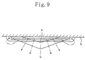
- In the aforementioned horizontal air supply condition, however, particulate dust contained in the conditioned air having been supplied may adhere to the ceiling surface to partially contaminate it. Specifically, in a horizontal view of the air conditioner as shown in Figure 9, the airflow supplied in the horizontal air supply condition through the air outlet (a) is substantially in V form as viewed along the airflow. Since the initial rate of air supply is higher at a longitudinally middle portion of the air outlet (a), the airflow at that portion will pass through a region away from the ceiling surface (b). Further, since particulate dust contained in such a supply air has a high inertia force; such dust seldom adheres to the ceiling surface (b).
- On the other hand, at both lateral side portions of the air outlet (a), the airflow diffuses laterally or forms vortex flows, i.e., the initial rate of air supply is lower as compared with the middle portion of the air outlet. Therefore, the airflow will travel along the ceiling surface (b) by Coanda effect. Further, in this case, since dust contained in the supply air has a low inertia force and therefore easily adheres to the ceiling surface (b), regions (D) of the ceiling surface (b) close to both lateral sides of the air outlet (a) can readily adhere dust in the air thereto resulting in ease contamination.
- To avoid such contamination, Japanese Unexamined Patent Publication 3-160266 has proposed that the horizontal vane is provided with a detachable auxiliary fin for shifting the air supply direction toward the ceiling surface and the auxiliary fin is attached or detached depending upon ease of production of contamination at the ceiling. Specifically, for example, the auxiliary fin may be detached to orient the horizontal vane downwards under environments where the room air contains much dust to readily produce contamination of the ceiling or at locations such as hospitals where demands for anti-contamination are particularly great, whereas the auxiliary fin may be attached to allow a horizontal air supply under environments where contamination of the ceiling may be hard to occur or at locations where demands for anti-contamination are small.
- However, even if such an auxiliary fin as used in the above prior art is provided, the auxiliary fin cannot help being detached under environments where contamination of the ceiling may readily occur and in this case, eventually, the conditioned air will always be blown out downwards from the air outlet. This not only incurs reduced air conditioning efficiency during cooling operation where a horizontal air supply should actually be conducted, but also causes a problem of an uncomfortable feeling (a so-called drafty feeling) of a person in the room resulting from direct blow of a cooled air.
- The present invention has been made in view of the above points and therefore has its object of preventing contamination of the ceiling surface while obtaining a suitable air supply direction in accordance with each operation mode of the air conditioner by exercising ingenuity on the design of the air outlet for the conditioned air.
- The present invention takes the following measures to solve the above problems.
- A first invention is directed to a ceiling-embedded type air conditioner (1) embedded in a ceiling surface (70) and provided with a laterally elongated air outlet (16) for supplying a conditioned air therethrough toward a room space and with a guide means (18) that is located in the air outlet (16) and has the ability to guide a supply of the conditioned air so that a supply direction of the conditioned air forms substantially 45° or less with respect to the ceiling surface (70). Further, the air outlet (16) is provided at least substantially at both longitudinal ends thereof with straightening members (19) for straightening the flow of the conditioned air into a two-dimensional flow along a vertical plane. It is to be noted that the guide means (18) is preferably adapted to curve an air passage upstream of the air outlet (16) so that the direction of the conditioned air to be supplied makes substantially 45 ° or less with the ceiling surface (70).
- With this invention, the conditioned air supplied through the air outlet (16) of the air conditioner (1) during cooling operation is guided by the guiding means (18) to form a jet blown out toward the room space at 45° or less with respect to the ceiling surface (70). The axis of the jet is turned toward the ceiling surface (70) due to Coanda effect. In this case, since the straightening members (19) are disposed at least substantially at both longitudinal ends of the air outlet (16), respectively, and straightens the flows of the conditioned air at both lateral side portions of the air outlet into two-dimensional flows along the vertical plane, the initial rate of supply of the conditioned air becomes as high also at both the lateral side portions as at the middle portion of the air outlet. Therefore, the airflows will not reach the ceiling surface (70) but will gradually go down in the course of time due to a temperature difference from the room air. Accordingly, even if the supply direction of the conditioned air is made upward so that the airflow will be approximately parallel to the ceiling surface, the airflow can be suppressed from traveling along the ceiling surface, thereby preventing contamination of the ceiling surface in a so-called horizontal air supply condition.
- In a second invention, it is arranged that in the first invention, the guide means (18) comprises a horizontal vane that allows up and down change in the supply direction of the conditioned air and straightening plates as the straightening members (19) are disposed on the horizontal vane (18). Further, it is preferable that an extension height (ωh) at which the straightening plate (19) extends from the horizontal vane (18) is 5mm or more and 30 mm or less (a third invention). Furthermore, it is further preferable that the extension height (ωh) is 22.5 mm (a fourth invention).
- With this invention, since the flow direction of the conditioned air from the air outlet (16) can be changed up and down by the horizontal vane (18), the flow of the supply air can be oriented relatively downward during heating operation, while it can be put into a horizontal air supply condition during cooling operation. The air conditioning efficiency can be thereby enhanced in each operation mode. Further, the flow of the supply air can be effectively straightened by the straightening plates (19) provided on the horizontal vane (18).
- In a fifth invention, it is arranged that in any one of the second to fourth inventions, the horizontal vane (18) is formed of an elongated plate member that curves over the width thereof and the plurality of straightening plates (19) are fixedly arranged on an inner curved surface of the horizontal vane (18) at a predetermined pitch over the entire length in a longitudinal direction of the horizontal vane (18). It is preferable that the pitch ( ωp) of the straightening plates (19) in respect of the longitudinal direction of the horizontal vane (18) is 10 mm or more and 60 mm or less (a sixth invention). Also, it is further preferable that the pitch (ωp) of the straightening plates (19) is 50 mm (a seventh invention). Further, it is preferable that the number of the straightening plates (19) to be arranged on each single horizontal vane (18) is 10 (an eighth invention).
- With this invention, the widthwise curved, elongated horizontal vane (18) can smoothly change the flow of the conditioned air to change the supply direction thereof. Further, since the straightening plates are fixedly arranged on the inner curved surface of the horizontal vane (18) over the entire length thereof, the flow of the supply air can entirely be straightened by these straightening plates.
- In a ninth invention, it is arranged that in the first invention, the guide means (18) comprises a horizontal vane that allows up and down change in the supply direction of the conditioned air and straightening plates as the straightening members (19) are disposed on an inclined surface (16b) opposed to a front face of the horizontal vane in an air passage connecting to the air outlet (16).
- With this invention, the same operations and effects as those of the second invention can be achieved.
- A tenth invention is directed to a ceiling-embedded type air conditioner (1) embedded in a ceiling surface (70) and provided with a laterally elongated air outlet (16) for supplying a conditioned air therethrough toward a room space and with a horizontal vane (18) that is located in the air outlet (16) and has the ability to guide a supply of the conditioned air. Further, the horizontal vane (18) is formed of an elongated plate member that curves over the width thereof, a plurality of straightening plates (19) are fixedly arranged on an inner curved surface of the horizontal vane (18) over the entire length thereof, and each of the straightening plates (19) is disposed to be substantially orthogonal to the inner surface of the horizontal vane (18) and extend over the width thereof.
- With this invention, the flow direction of the conditioned air from the air outlet (16) of the air conditioner (1) can be changed up and down by the horizontal vane (18). Therefore, if the flow of the supply air is relatively downward during heating operation while it is put into a horizontal air supply condition during cooling operation, the air conditioning efficiency can be enhanced in each operation mode. Further, the widthwise curved, elongated horizontal vane (18) can smoothly change the flow of the conditioned air.
- Furthermore, the straightening plates (19) fixedly arranged on the inner curved surface of the horizontal vane (18) can straighten the flow of the supply air so that the entire flow thereof including partial flows at both the lateral sides of the air outlet (16) can be formed into a two-dimensional flow along the vertical plane. Thus, the partial airflows at both the lateral sides of the air outlet (16) also increase in the initial rate of supply of the conditioned air like the partial airflow at the middle of the air outlet (16). Accordingly, even in a so-called horizontal air supply condition during for example the cooling operation, it can be suppressed that the flow of the conditioned air travels along the ceiling surface (70), which can prevent contamination of the ceiling surface.
- According to the present invention, in the ceiling-embedded type air conditioner (1) embedded in the ceiling surface (70) and provided with the air outlet (16) for supplying a conditioned air therethrough at substantially 45° or less with respect to the ceiling surface (70), the air outlet (16) is provided at least substantially at both longitudinal ends thereof with straightening members (19) for straightening the flow of the conditioned air into a two-dimensional flow along the vertical plane. Thus, even when the conditioned air is supplied through the air outlet (16) of the air conditioner (1) during for example cooling operation so as to be as parallel to the ceiling surface as possible, the flow of the conditioned air can be suppressed from traveling along the ceiling surface thereby preventing the occurrence of contamination at the ceiling.
- Further, according to the second invention, the supply direction of the conditioned air can be changed up and down by the horizontal vane (18) in accordance with each operation mode of the air conditioner, resulting in enhanced air conditioning efficiency. In addition, the straightening plates (19) disposed on the horizontal vane (18) can effectively straighten the flow of the supply air.
- Furthermore, according to the fifth invention, the flow of the conditioned air can be smoothly changed by the horizontal vane (18) and at the same time, can be effectively straightened over the entire length of the air outlet (16).
- Further, according to the ninth invention, the same effects can be obtained as those of the second invention.
- Still further, according to the tenth invention, the same effects can be obtained as those of the first to third inventions.
-
- Figure 1 is a schematic cross-sectional view of an air conditioner according to an embodiment of the present invention when viewed from sideward.
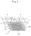
- Figure 2 is a perspective view of the air conditioner embedded in a ceiling when viewed from below.
- Figure 3 is an enlarged view showing detailed structures of an air outlet and a horizontal vane.
- Figure 4 is a view corresponding to Figure 3 when the supply direction of a conditioned air is oriented downward.
- Figure 5 is a perspective view of the horizontal vane.
- Figure 6 is a front view of the horizontal vane.
- Figure 7 is a top view of Figure 6.
- Figure 8 is a side view of Figure 6.
- Figure 9 is an explanatory diagram showing an airflow state of a conditioned air supplied through an air outlet of a conventional air conditioner when viewed from sideward.
-
- Below, embodiments of the present invention will be described in detail with reference to the drawings.
- Figure 1 is a longitudinal cross-sectional view showing the structure of an embodiment of a ceiling-embedded type air conditioner (1) according to the present invention. As shown in this figure, this air conditioner (1) is composed so that a fan (20) and a heat exchanger (30) are contained in a casing (10), and is installed in a space at the back of a ceiling so as to be set in an installation opening (71) formed in a ceiling board (70).
- The casing (10) is formed of a container-like body casing (11) that opens downward and a decorative panel (14) that covers a bottom opening of the body casing (11), and is fixed so as to be suspended from a beam or the like located above through a hanger although they are not shown. Specifically, the body casing (11) is composed of a top board (12) shaped in an octagon by cutting away four corners of a square and a side board (13) extending downward from an outer edge of the top board (12). On the other hand, the decorative panel (14) is formed in a substantially square plate and attached to a lower end of the side board (13), and the top face of its peripheral portion engages against the bottom face of the ceiling board (70).
- Further, as also shown in Figure 2, the decorative panel (14) is formed at its substantially middle portion with an air inlet (15) that opens in the form of a square, and formed with four elongated, rectangular air outlets (16) immediately outside and along the respective four sides of the air inlet (15). Furthermore, an air filter (17) for removing floating substances such as particulate dust contained in the room air is provided over the entire area of the air inlet (5), and its entire bottom face is supported on a lattice-like filter cover. On the other hand, horizontal vanes (18) that can change the supply direction of the conditioned air up and down are disposed in the respective air outlets (16).
- Specifically, as shown in enlarged manner in Figures 3 and 4, out of sidewalls of an air passage that communicates with the air outlet (16) of the decorative panel (14), the sidewall on the side of the outer periphery of the decorative panel (14) (right-hand side of the figures) is formed of: a vertical surface (16a) extending substantially vertically downward; and an inclined surface (16b) that is inclined from the lower end of the vertical surface (16a) downwardly in the direction toward the panel outer periphery and connects with the bottom face of the decorative panel (14). On the other hand, out of the sidewalls of the same air passage that communicates with the air outlet (16), the sidewall on the side of the inner periphery of the decorative panel (14) (left-hand side of the figures) is formed of: a curved surface (16c) that gradually extends toward the panel outer periphery as it goes downward; and a vertical surface (16d) that extends from the lower end of the curved surface (16c) substantially vertically downward. These two opposed wall surfaces having such surface forms are formed over the entire length of the air outlet (16) in the longitudinal direction (a direction orthogonal to the paper). The air passage interposed between both the wall surfaces has a function as a run-up passage that changes the flow direction of the conditioned air while straightening the flow of the conditioned air toward the outlet (16). Further, in the run-up passage, the run-up distance of the conditioned air up to the outlet (16) is set at substantially 30 mm or more.
- Further, as each shown in Figures 5 to 8, the horizontal vane (18) is formed of an elongated plate member and slightly curved over the width so that the inner curved surface (18a) forms a front face while the outer curved surface (18b) forms a back face. Both lengthwise ends of the horizontal vane (18) are provided integrally with respective shell-shaped extensions (18c, 18c) that extends on the front face side, and ends of the extensions (18c) are provided with respective connecting pins (18d, 18d) to extend outward along the length of the horizontal vane (18). Furthermore, the horizontal vane (18), with attached to the outlet (16), is connected and supported for free rotation to the decorative cover (14) by the two connecting pins (18d, 18d) located inside of the air outlet (16) (on the upstream side of the conditioned air flow), and arranged to rotate about a support axis x by a drive of an unshown motor.
- Furthermore, as a feature of the present invention, a plurality of (ten in the illustrated example) straightening plates (19, 19, ...) for straightening the flow of the conditioned air are fixedly arranged on the inner curved front face (18a) of the horizontal vane (18) at a predetermined pitch (ωp) over the entire length in the longitudinal direction of the horizontal vane (18). Each of these straightening plates (19) is placed over the width of the horizontal vane (18) so as to be substantially orthogonal to the front face (18a) of the horizontal vane (18). As shown in the arrow S in Figure 5, the conditioned air that flows between respective adjacent straightening plates (19) along the front face (18a) of the horizontal vane (18) will be thereby straightened over the entire length of the horizontal vane (18).
- As shown in Figures 6 and 7, it is preferable that the pitch (ωp) of the straightening plates (19) in respect of the longitudinal direction of the horizontal vane (18) is 10 mm or more and 60 mm or less. In this embodiment, however, the pitch (ωp) of the straightening plates (19) is set at 50 mm as a more preferable value. Further, it is preferable that the extension height (ωh) at which each straightening plate (19) extends from the horizontal vane (18) is 5 mm or more and 30 mm or less. In this embodiment, however, the extension height (ωh) is set at 22.5 mm as a more preferable value.
- Furthermore, when the conditioned air is blown out most downwardly through the air outlet (16), the horizontal vane (18) is oriented downward so that its back face (8b) overlies the vertical surface (16d) on the panel inner periphery side as shown in Figure 4. On the other hand, when the conditioned air is in its horizontal air supply condition, the horizontal vane (18) is oriented upward so that its front face (18b) is substantially parallel to the inclined surface (16b) of the sidewall on the panel outer periphery side.
- The fan (20) is provided at a substantially middle position inside of the body casing (11) and serves as a so-called turbo fan in which blades (23) are held between a shroud (21) and a hub (22). A drive shaft (26) of a fan motor (25) mounted on the top board (12) of the body casing (11) is fixedly inserted into the hub (22) of this fan (20). The fan (20) is driven into rotation by a driving force of the fan motor (25) to feed an air, having been sucked from below the fan (20), diametrically sideward. Furthermore, a bellmouth (27) for guiding the air, having flowed into the casing (10) through the air inlet (15), to the fan (20) is provided below the fan (20).
- Further, the heat exchanger (30) is a so-called finned tube heat exchanger composed of a number of plate-shaped fins (31) arranged in parallel with each other and a heat-transfer pipe (32) provided through the fins (31). The heat exchanger (30) is formed in a rectangular cylinder when viewed in a plane to surround the fan (20), and connected to an outdoor unit via an unshown refrigerant pipe to perform a function as an evaporator during cooling operation and a function as a condenser during heating operation thereby controlling the temperature conditions of the air fed from the fan (20). Furthermore, a drain pan (33) for receiving drainage is provided below the heat exchanger (30).
- In short, the body casing (11) of the air conditioner (1) forms thereinside an airflow passage (W) leading from the air inlet (15) of the decorative panel (14) to the air outlet (16) through the air filter (17), the bellmounth (27), the fan (20) and the heat exchanger (30). When the fan (20) is driven during air conditioning, the room air taken into the casing (10) via the air filter (17) through the air inlet (15) flows through the airflow passage (W) in the order of the bellmouth (27), the fan (20) and the heat exchanger (30), exchanges heat with refrigerant in the heat exchanger (30) to experience temperature control (i.e., to be cooled during cooling operation or to be heated during heating operation), and is then supplied to the room space through the air outlet (16), thus performing air conditioning of the room space.
- More specifically, first, if there is a demand for the conditioned air being supplied comparatively downward during for example heating operation, the horizontal vane (18) is oriented substantially vertically downward as shown in Figure 4 so that the conditioned air is supplied substantially vertically downward along the horizontal vane (18) and the vertical surface (16a) of the air outlet (16) on the panel outer periphery side as shown in the arrow S in the same figure.
- On the other hand, if the supply air is put into a so-called horizontal air supply condition during for example cooling operation, the horizontal vane (18) is upwardly rotated as shown in Figure 3 so that the front face (18a) of the horizontal vane (18) is made substantially parallel with the inclined surface (16b) of the sidewall of the air outlet (16) on the panel outer peripheral side. In this manner, the conditioned air flows along the sidewalls of the guide passage communicating with the air outlet (16), i.e., flows in a curved path along the curved surface (6c) and then front face (18a) of the horizontal vane (18), changes widely and smoothly its direction of the flux line, passes between the inclined surface (16b) of the air outlet (16) on the panel outer periphery side and the horizontal vane (18) as shown in the arrow S in the figure, and is then blown out through the air outlet (16) at an angle approximately parallel to the bottom face of the ceiling board (70) (for example, an angle of approximately 25 ° to 35 ° with the bottom face of the ceiling board (70)).
- In this case, the conditioned air supplied to the room space through the air outlet (16) forms a jet. When the supply angle of the air is approximately parallel to the bottom face of the ceiling board (70), the axis of the jet will be bent upward by Coanda effect. In this embodiment, however, the straightening plates (19, 19, ...) are provided on the front face (18a) of the horizontal vane (18) as described above and therefore the flow guided by the horizontal vane (18) is straightened by the straightening plates (19, 19, ...).
- Accordingly, the airflow is restrained from laterally diffusing or forming vortex flows even at both lateral side portions of the air outlet (16) and instead supplied to the room space as a two-dimensional flow generally traveling along the vertical plane (a plane including the section in the figure). As a result, also at both lateral side portions of the air outlet (16), the initial rate of supply of the conditioned air becomes sufficiently high as at the middle portion thereof. The airflow does not reach the ceiling surface (70) but gradually goes down in the course of time due to a temperature difference from the room air.
- In the portion of the conventional ceiling-embedded type air conditioner where the rate of air supply is low, the airflow is easy to approach the bottom face of the ceiling board (70) by Coanda effect. If the supply direction of the conditioned air is oriented relatively upward by the horizontal vane (18) during cooling operation so as to be set at for example 40 to 45 degrees with respect to the bottom face of the ceiling board (70), the airflow will flow along the bottom face of the ceiling board (70) so that ceiling contamination occurs in the regions (D) as shown in imaginary lines in Figure 2. On the other hand, in the air conditioner (1) according to this embodiment, the horizontal vane (18) is provided with the straightening plates (19, 19, ...) to straighten the flow of the conditioned air into a two-dimensional flow along the vertical plane. Therefore, particularly during cooling operation which needs a horizontal supply of the conditioned air, the horizontal vane (18) can make the supply direction of the conditioned air approach up to about 25 to about 35 degrees with respect to the bottom face of the ceiling board (70) to thereby ensure a high air conditioning efficiency and eliminate an uncomfortable feeling (drafty feeling) of a person lived in the room. In addition, at the same time, the flow of the conditioned air can be restrained from flowing along the bottom face of the ceiling board (70), which prevents the occurrence of ceiling contamination that has conventionally been a problem.
- The present invention is not limited to the above embodiment but includes a variety of other embodiments. Specifically, in the above embodiment, the straightening plates (19, 19, ...) as straightening members are arranged on the front face (18a) of the horizontal vane (18).However, the straightening plates (19, 19, ...) are not limited to the above arrangement but, for example, may be arranged on the inclined surface (16b) of the air outlet (16) that is opposed to the front face (18a) of the horizontal vane (18). Further, the straightening plates (19, 19, ...) are not necessarily arranged over the entire length in the longitudinal direction of the air outlet (16) but may only be arranged to correspond substantially to both the ends of the air outlet (16).
- Further, in the above embodiment, the horizontal vane (18) is disposed in the air outlet (16) to change the flow direction of the conditioned air up and down. However, the flow of the conditioned air may be guided only by the curved design of the air passage leading to the air outlet (16) without the horizontal vane (18) being disposed. In this case, the air passage itself constitutes a guide means.
- In addition, in the above embodiment, the present invention is applied to a so-called ceiling-embedded 4-directional supply type air conditioner (1) that includes a turbo fan to supply the conditioned air in four directions. The present invention, however, is not limited to this type but can be applied to, for example, a so-called ceiling-embedded bidirectional supply type air conditioner that includes a silocco fan to supply in two directions.
- As can be seen from the above, the ceiling-embedded type air conditioner can prevent contamination of the ceiling surface while providing a suitable air supply direction in accordance with its operation mode and is therefore suitable for use at locations such as hospitals where demands for anti-contamination are particularly great.
Claims (10)
- A ceiling-embedded type air conditioner embedded in a ceiling surface (70) and provided with a laterally elongated air outlet (16) for supplying a conditioned air therethrough toward a room space and with guide means (18) that is located in the air outlet (16) and has the ability to guide a supply of the conditioned air so that a supply direction of the conditioned air forms substantially 45° or less with respect to the ceiling surface (70), characterized in that
the air outlet (16) is provided at least substantially at both longitudinal ends thereof with straightening members (19) for straightening the flow of the conditioned air into a two-dimensional flow along a vertical plane. - The ceiling-embedded type air conditioner of Claim 1, characterized in thatthe guide means (18) comprises a horizontal vane that allows up and down change in the supply direction of the conditioned air, andthe straightening member (19) comprises a straightening plate disposed on the horizontal vane (18).
- The ceiling-embedded type air conditioner of Claim 2, characterized in that
an extension height (ωh) at which the straightening plate (19) extends from the horizontal vane (18) is set at 5mm or more and 30 mm or less. - The ceiling-embedded type air conditioner of Claim 3, characterized in that
the extension height (ωh) of the straightening plate (19) from the horizontal vane (18) is 22.5 mm. - The ceiling-embedded type air conditioner of any one of Claims 2 to 4, characterized in thatthe horizontal vane (18) is formed of an elongated plate member that curves over the width thereof, andthe plurality of straightening plates (19) are fixedly arranged on an inner curved surface of the horizontal vane (18) at a predetermined pitch over the entire length in a longitudinal direction of the horizontal vane (18).
- The ceiling-embedded type air conditioner of Claim 5, characterized in that
the pitch (ωp) of the straightening plates (19) in respect of the longitudinal direction of the horizontal vane (18) is 10 mm or more and 60 mm or less. - The ceiling-embedded type air conditioner of Claim 6, characterized in that
the pitch (ωp) of the straightening plates (19) is 50 mm. - The ceiling-embedded type air conditioner of Claim 5, characterized in that
the number of the straightening plates (19) to be arranged on each single horizontal vane (18) is 10. - The ceiling-embedded type air conditioner of Claim 1, characterized in thatthe guide means (18) comprises a horizontal vane that allows up and down change in the supply direction of the conditioned air, andthe straightening member (19) comprises a straightening plate that is disposed on an inclined surface (16b) opposed to a front face of the horizontal vane in an air passage connecting to the air outlet (16).
- A ceiling-embedded type air conditioner embedded in a ceiling surface (70) and provided with a laterally elongated air outlet (16) for supplying a conditioned air therethrough toward a room space and with a horizontal vane (18) that is located in the air outlet (16) and has the ability to guide a supply of the conditioned air, characterized in thatthe horizontal vane (18) is formed of an elongated plate member that curves over the width thereof,a plurality of the straightening plates (19) are fixedly arranged on an inner curved surface of the horizontal vane (18) over the entire length thereof, andeach of the straightening plates (19) is disposed to be substantially orthogonal to the inner surface of the horizontal vane (18) and extend over the width thereof.
Applications Claiming Priority (3)
| Application Number | Priority Date | Filing Date | Title |
|---|---|---|---|
| JP31582699A JP3282616B2 (en) | 1999-11-05 | 1999-11-05 | Ceiling-mounted air conditioner |
| JP31582699 | 1999-11-05 | ||
| PCT/JP2000/005736 WO2001035032A1 (en) | 1999-11-05 | 2000-08-25 | Ceiling-embedded type air conditioner |
Publications (2)
| Publication Number | Publication Date |
|---|---|
| EP1152193A1 true EP1152193A1 (en) | 2001-11-07 |
| EP1152193A4 EP1152193A4 (en) | 2003-05-14 |
Family
ID=18070040
Family Applications (1)
| Application Number | Title | Priority Date | Filing Date |
|---|---|---|---|
| EP00955017A Withdrawn EP1152193A4 (en) | 1999-11-05 | 2000-08-25 | Ceiling-embedded type air conditioner |
Country Status (5)
| Country | Link |
|---|---|
| EP (1) | EP1152193A4 (en) |
| JP (1) | JP3282616B2 (en) |
| CN (2) | CN1162661C (en) |
| AU (1) | AU755459B2 (en) |
| WO (1) | WO2001035032A1 (en) |
Cited By (15)
| Publication number | Priority date | Publication date | Assignee | Title |
|---|---|---|---|---|
| EP1319900A1 (en) * | 2001-12-13 | 2003-06-18 | Lg Electronics Inc. | Air conditioner and method for controlling the same |
| NL1022895C2 (en) * | 2003-03-11 | 2004-09-14 | Inteco B V | Ceiling connector for emitting cold or warm air, includes valve for altering direction of air in response to need for cooling or heating of room |
| EP1589292A1 (en) * | 2004-04-23 | 2005-10-26 | Unico Consumer Products Co., Ltd. | Ceiling-recessed air treatment apparatus |
| EP1619452A1 (en) * | 2004-07-23 | 2006-01-25 | Biddle B.V. | Ventilation apparatus with peripheral outflow |
| EP1688678A1 (en) * | 2003-11-27 | 2006-08-09 | Daikin Industries, Ltd. | Air conditioner |
| EP1816404A3 (en) * | 2006-02-07 | 2012-02-01 | LG Electronics, Inc. | Indoor unit of air conditioner |
| CN104807081A (en) * | 2014-01-27 | 2015-07-29 | Lg电子株式会社 | Indoor device for air conditioner having wind visors |
| EP3086051A4 (en) * | 2013-12-20 | 2017-08-30 | Mitsubishi Electric Corporation | Air conditioner |
| WO2017218108A1 (en) * | 2016-06-15 | 2017-12-21 | Roca Richard | Improved led heating lamp and fan |
| US10047972B2 (en) | 2013-10-02 | 2018-08-14 | Lg Electronics Inc. | Indoor device for cassette type air conditioner |
| US10197298B2 (en) | 2013-10-02 | 2019-02-05 | Lg Electronics Inc. | Indoor device for cassette type air conditioner |
| US10203150B2 (en) | 2013-10-11 | 2019-02-12 | Lg Electronics Inc. | Indoor device for air conditioner |
| EP3450870A4 (en) * | 2016-04-27 | 2019-04-10 | Mitsubishi Electric Corporation | Air conditioner |
| EP3805657A4 (en) * | 2018-09-14 | 2021-08-18 | Gree Electric Appliances, Inc. of Zhuhai | Air-out duct structure, air-out panel and ceiling air conditioner indoor unit |
| DE102020118766A1 (en) | 2020-07-16 | 2022-01-20 | Denis Limburg | Plenum independent modular recirculation device |
Families Citing this family (11)
| Publication number | Priority date | Publication date | Assignee | Title |
|---|---|---|---|---|
| JP4513548B2 (en) * | 2004-12-22 | 2010-07-28 | パナソニック株式会社 | Air conditioner indoor unit |
| JP5745480B2 (en) * | 2012-09-12 | 2015-07-08 | 三菱電機株式会社 | Air conditioner |
| CN105264300B (en) * | 2013-06-12 | 2018-09-28 | 松下知识产权经营株式会社 | Air conditioner |
| AU2015226832B2 (en) | 2014-03-06 | 2019-05-16 | Dometic Sweden Ab | Improved air conditioning system |
| CN103939984A (en) * | 2014-03-31 | 2014-07-23 | 美的集团武汉制冷设备有限公司 | Indoor unit of air conditioner |
| CN104266264B (en) * | 2014-10-16 | 2016-09-21 | 上海圣峰建材科技有限公司 | A kind of Integral ceiling air-conditioning and mounting structure thereof |
| US10288302B2 (en) * | 2015-03-31 | 2019-05-14 | Fujitsu General Limited | Ceiling-embedded air conditioner with airflow guide vane |
| JP6504349B2 (en) * | 2015-03-31 | 2019-04-24 | 株式会社富士通ゼネラル | Ceiling-mounted air conditioner |
| KR102508221B1 (en) | 2015-11-20 | 2023-03-10 | 삼성전자주식회사 | Indoor unit of air conditioner |
| WO2018216415A1 (en) * | 2017-05-24 | 2018-11-29 | ダイキン工業株式会社 | Indoor unit for air conditioner |
| JP7065271B2 (en) * | 2017-11-30 | 2022-05-12 | パナソニックIpマネジメント株式会社 | Blower and bathroom heater / dryer equipped with it |
Citations (4)
| Publication number | Priority date | Publication date | Assignee | Title |
|---|---|---|---|---|
| JPH08285303A (en) * | 1995-04-11 | 1996-11-01 | Daikin Ind Ltd | Air conditioning equipment |
| JPH0914742A (en) * | 1995-06-29 | 1997-01-17 | Mitsubishi Heavy Ind Ltd | Air conditioner |
| JPH10160238A (en) * | 1996-11-29 | 1998-06-19 | Mitsubishi Electric Corp | Flush type air-conditioner |
| JPH10238806A (en) * | 1997-02-24 | 1998-09-08 | Matsushita Electric Ind Co Ltd | Ceiling embedded air conditioner |
Family Cites Families (2)
| Publication number | Priority date | Publication date | Assignee | Title |
|---|---|---|---|---|
| JP3240854B2 (en) * | 1994-09-26 | 2001-12-25 | 三菱電機株式会社 | Air conditioner outlet |
| JP3061026B2 (en) * | 1997-12-18 | 2000-07-10 | ダイキン工業株式会社 | Air conditioner indoor unit |
-
1999
- 1999-11-05 JP JP31582699A patent/JP3282616B2/en not_active Expired - Fee Related
-
2000
- 2000-08-25 AU AU67303/00A patent/AU755459B2/en not_active Ceased
- 2000-08-25 WO PCT/JP2000/005736 patent/WO2001035032A1/en not_active Application Discontinuation
- 2000-08-25 EP EP00955017A patent/EP1152193A4/en not_active Withdrawn
- 2000-08-30 CN CNB001268015A patent/CN1162661C/en not_active Expired - Fee Related
- 2000-08-31 CN CN00248330U patent/CN2442168Y/en not_active Expired - Lifetime
Patent Citations (4)
| Publication number | Priority date | Publication date | Assignee | Title |
|---|---|---|---|---|
| JPH08285303A (en) * | 1995-04-11 | 1996-11-01 | Daikin Ind Ltd | Air conditioning equipment |
| JPH0914742A (en) * | 1995-06-29 | 1997-01-17 | Mitsubishi Heavy Ind Ltd | Air conditioner |
| JPH10160238A (en) * | 1996-11-29 | 1998-06-19 | Mitsubishi Electric Corp | Flush type air-conditioner |
| JPH10238806A (en) * | 1997-02-24 | 1998-09-08 | Matsushita Electric Ind Co Ltd | Ceiling embedded air conditioner |
Non-Patent Citations (5)
| Title |
|---|
| PATENT ABSTRACTS OF JAPAN vol. 1997, no. 03, 31 March 1997 (1997-03-31) -& JP 08 285303 A (DAIKIN IND LTD), 1 November 1996 (1996-11-01) * |
| PATENT ABSTRACTS OF JAPAN vol. 1997, no. 05, 30 May 1997 (1997-05-30) -& JP 09 014742 A (MITSUBISHI HEAVY IND LTD), 17 January 1997 (1997-01-17) * |
| PATENT ABSTRACTS OF JAPAN vol. 1998, no. 11, 30 September 1998 (1998-09-30) & JP 10 160238 A (MITSUBISHI ELECTRIC CORP), 19 June 1998 (1998-06-19) * |
| PATENT ABSTRACTS OF JAPAN vol. 1998, no. 14, 31 December 1998 (1998-12-31) -& JP 10 238806 A (MATSUSHITA ELECTRIC IND CO LTD), 8 September 1998 (1998-09-08) * |
| See also references of WO0135032A1 * |
Cited By (21)
| Publication number | Priority date | Publication date | Assignee | Title |
|---|---|---|---|---|
| EP1319900A1 (en) * | 2001-12-13 | 2003-06-18 | Lg Electronics Inc. | Air conditioner and method for controlling the same |
| NL1022895C2 (en) * | 2003-03-11 | 2004-09-14 | Inteco B V | Ceiling connector for emitting cold or warm air, includes valve for altering direction of air in response to need for cooling or heating of room |
| EP1688678A1 (en) * | 2003-11-27 | 2006-08-09 | Daikin Industries, Ltd. | Air conditioner |
| EP1688678A4 (en) * | 2003-11-27 | 2009-02-25 | Daikin Ind Ltd | Air conditioner |
| US8006512B2 (en) | 2003-11-27 | 2011-08-30 | Daikin Industries, Ltd. | Air conditioner |
| EP1589292A1 (en) * | 2004-04-23 | 2005-10-26 | Unico Consumer Products Co., Ltd. | Ceiling-recessed air treatment apparatus |
| EP1619452A1 (en) * | 2004-07-23 | 2006-01-25 | Biddle B.V. | Ventilation apparatus with peripheral outflow |
| EP1816404A3 (en) * | 2006-02-07 | 2012-02-01 | LG Electronics, Inc. | Indoor unit of air conditioner |
| US10197298B2 (en) | 2013-10-02 | 2019-02-05 | Lg Electronics Inc. | Indoor device for cassette type air conditioner |
| US10047972B2 (en) | 2013-10-02 | 2018-08-14 | Lg Electronics Inc. | Indoor device for cassette type air conditioner |
| US10203150B2 (en) | 2013-10-11 | 2019-02-12 | Lg Electronics Inc. | Indoor device for air conditioner |
| EP3086051A4 (en) * | 2013-12-20 | 2017-08-30 | Mitsubishi Electric Corporation | Air conditioner |
| CN104807081A (en) * | 2014-01-27 | 2015-07-29 | Lg电子株式会社 | Indoor device for air conditioner having wind visors |
| US10203124B2 (en) | 2014-01-27 | 2019-02-12 | Lg Electronics Inc. | Indoor device for air conditioner having wind visors |
| EP3450870A4 (en) * | 2016-04-27 | 2019-04-10 | Mitsubishi Electric Corporation | Air conditioner |
| US11029058B2 (en) | 2016-04-27 | 2021-06-08 | Mitsubishi Electric Corporation | Air conditioner |
| WO2017218108A1 (en) * | 2016-06-15 | 2017-12-21 | Roca Richard | Improved led heating lamp and fan |
| US10208946B2 (en) | 2016-06-15 | 2019-02-19 | Richard Roca | LED heating lamp and fan |
| EP3805657A4 (en) * | 2018-09-14 | 2021-08-18 | Gree Electric Appliances, Inc. of Zhuhai | Air-out duct structure, air-out panel and ceiling air conditioner indoor unit |
| US11988400B2 (en) | 2018-09-14 | 2024-05-21 | Gree Electric Appliances, Inc. Of Zhuhai | Air-outlet duct structure, air-outlet panel and patio type air conditioner indoor unit |
| DE102020118766A1 (en) | 2020-07-16 | 2022-01-20 | Denis Limburg | Plenum independent modular recirculation device |
Also Published As
| Publication number | Publication date |
|---|---|
| CN2442168Y (en) | 2001-08-08 |
| WO2001035032A1 (en) | 2001-05-17 |
| JP2001132976A (en) | 2001-05-18 |
| JP3282616B2 (en) | 2002-05-20 |
| AU755459B2 (en) | 2002-12-12 |
| CN1295222A (en) | 2001-05-16 |
| EP1152193A4 (en) | 2003-05-14 |
| CN1162661C (en) | 2004-08-18 |
| AU6730300A (en) | 2001-06-06 |
Similar Documents
| Publication | Publication Date | Title |
|---|---|---|
| EP1152193A1 (en) | Ceiling-embedded type air conditioner | |
| EP1326054B1 (en) | Decorative panel for air conditioning system, air outlet unit, and air conditioning system | |
| JP6022003B2 (en) | Air conditioner indoor unit | |
| JP3438684B2 (en) | Ceiling embedded air conditioner | |
| EP1310743B1 (en) | Decorative panel and diffuser unit of air conditioner, and air conditioner | |
| WO2014199590A1 (en) | Air conditioner | |
| EP1316760B1 (en) | Decorative panel for air conditioning system, air outlet blow-off unit, and air conditioning system | |
| JP3285023B2 (en) | Ceiling-mounted air conditioner | |
| JP6739619B2 (en) | Indoor unit of air conditioner | |
| EP1052457B1 (en) | Indoor unit for air conditioner | |
| JP7022739B2 (en) | Air conditioner | |
| JP2910628B2 (en) | Air conditioner | |
| JPH0972300A (en) | Blower | |
| JP2010216750A (en) | Air conditioner | |
| JP5112239B2 (en) | Air conditioner | |
| KR20230106451A (en) | Air conditioner | |
| JPH08313040A (en) | Wind-direction adjusting mechanism of air conditioner | |
| JP2005241069A (en) | Air conditioner | |
| JP2000018632A (en) | Air conditioner | |
| JPS5845422A (en) | Integral type air conditioner |
Legal Events
| Date | Code | Title | Description |
|---|---|---|---|
| PUAI | Public reference made under article 153(3) epc to a published international application that has entered the european phase |
Free format text: ORIGINAL CODE: 0009012 |
|
| 17P | Request for examination filed |
Effective date: 20010726 |
|
| AK | Designated contracting states |
Kind code of ref document: A1 Designated state(s): AT BE CH CY DE DK ES FI FR GB GR IE IT LI LU MC NL PT SE |
|
| AX | Request for extension of the european patent |
Free format text: AL;LT;LV;MK;RO;SI |
|
| A4 | Supplementary search report drawn up and despatched |
Effective date: 20030331 |
|
| RBV | Designated contracting states (corrected) |
Designated state(s): BE DE ES FR GB IT |
|
| 17Q | First examination report despatched |
Effective date: 20050314 |
|
| GRAP | Despatch of communication of intention to grant a patent |
Free format text: ORIGINAL CODE: EPIDOSNIGR1 |
|
| STAA | Information on the status of an ep patent application or granted ep patent |
Free format text: STATUS: THE APPLICATION IS DEEMED TO BE WITHDRAWN |
|
| 18D | Application deemed to be withdrawn |
Effective date: 20061229 |