EP1152182A1 - Surgical microscope - Google Patents
Surgical microscope Download PDFInfo
- Publication number
- EP1152182A1 EP1152182A1 EP00108786A EP00108786A EP1152182A1 EP 1152182 A1 EP1152182 A1 EP 1152182A1 EP 00108786 A EP00108786 A EP 00108786A EP 00108786 A EP00108786 A EP 00108786A EP 1152182 A1 EP1152182 A1 EP 1152182A1
- Authority
- EP
- European Patent Office
- Prior art keywords
- microscope
- sensors
- stand according
- axis
- tripod
- Prior art date
- Legal status (The legal status is an assumption and is not a legal conclusion. Google has not performed a legal analysis and makes no representation as to the accuracy of the status listed.)
- Granted
Links
- 230000003287 optical effect Effects 0.000 claims abstract description 6
- 230000005484 gravity Effects 0.000 claims description 6
- 239000000725 suspension Substances 0.000 claims description 3
- 230000001939 inductive effect Effects 0.000 claims description 2
- 230000003750 conditioning effect Effects 0.000 claims 1
- 230000000694 effects Effects 0.000 description 4
- 230000007935 neutral effect Effects 0.000 description 3
- 230000008859 change Effects 0.000 description 2
- 230000001965 increasing effect Effects 0.000 description 2
- 238000001356 surgical procedure Methods 0.000 description 2
- 230000009471 action Effects 0.000 description 1
- 230000008901 benefit Effects 0.000 description 1
- 210000004556 brain Anatomy 0.000 description 1
- 238000006073 displacement reaction Methods 0.000 description 1
- 238000011156 evaluation Methods 0.000 description 1
- 238000000034 method Methods 0.000 description 1
- 238000004091 panning Methods 0.000 description 1
- 230000004044 response Effects 0.000 description 1
- 230000000630 rising effect Effects 0.000 description 1
- 210000000278 spinal cord Anatomy 0.000 description 1
- 230000001360 synchronised effect Effects 0.000 description 1
Images
Classifications
-
- F—MECHANICAL ENGINEERING; LIGHTING; HEATING; WEAPONS; BLASTING
- F16—ENGINEERING ELEMENTS AND UNITS; GENERAL MEASURES FOR PRODUCING AND MAINTAINING EFFECTIVE FUNCTIONING OF MACHINES OR INSTALLATIONS; THERMAL INSULATION IN GENERAL
- F16M—FRAMES, CASINGS OR BEDS OF ENGINES, MACHINES OR APPARATUS, NOT SPECIFIC TO ENGINES, MACHINES OR APPARATUS PROVIDED FOR ELSEWHERE; STANDS; SUPPORTS
- F16M11/00—Stands or trestles as supports for apparatus or articles placed thereon ; Stands for scientific apparatus such as gravitational force meters
- F16M11/42—Stands or trestles as supports for apparatus or articles placed thereon ; Stands for scientific apparatus such as gravitational force meters with arrangement for propelling the support stands on wheels
-
- A—HUMAN NECESSITIES
- A61—MEDICAL OR VETERINARY SCIENCE; HYGIENE
- A61B—DIAGNOSIS; SURGERY; IDENTIFICATION
- A61B90/00—Instruments, implements or accessories specially adapted for surgery or diagnosis and not covered by any of the groups A61B1/00 - A61B50/00, e.g. for luxation treatment or for protecting wound edges
- A61B90/20—Surgical microscopes characterised by non-optical aspects
- A61B90/25—Supports therefor
-
- A—HUMAN NECESSITIES
- A61—MEDICAL OR VETERINARY SCIENCE; HYGIENE
- A61B—DIAGNOSIS; SURGERY; IDENTIFICATION
- A61B90/00—Instruments, implements or accessories specially adapted for surgery or diagnosis and not covered by any of the groups A61B1/00 - A61B50/00, e.g. for luxation treatment or for protecting wound edges
- A61B90/50—Supports for surgical instruments, e.g. articulated arms
-
- F—MECHANICAL ENGINEERING; LIGHTING; HEATING; WEAPONS; BLASTING
- F16—ENGINEERING ELEMENTS AND UNITS; GENERAL MEASURES FOR PRODUCING AND MAINTAINING EFFECTIVE FUNCTIONING OF MACHINES OR INSTALLATIONS; THERMAL INSULATION IN GENERAL
- F16M—FRAMES, CASINGS OR BEDS OF ENGINES, MACHINES OR APPARATUS, NOT SPECIFIC TO ENGINES, MACHINES OR APPARATUS PROVIDED FOR ELSEWHERE; STANDS; SUPPORTS
- F16M11/00—Stands or trestles as supports for apparatus or articles placed thereon ; Stands for scientific apparatus such as gravitational force meters
- F16M11/02—Heads
- F16M11/18—Heads with mechanism for moving the apparatus relatively to the stand
-
- F—MECHANICAL ENGINEERING; LIGHTING; HEATING; WEAPONS; BLASTING
- F16—ENGINEERING ELEMENTS AND UNITS; GENERAL MEASURES FOR PRODUCING AND MAINTAINING EFFECTIVE FUNCTIONING OF MACHINES OR INSTALLATIONS; THERMAL INSULATION IN GENERAL
- F16M—FRAMES, CASINGS OR BEDS OF ENGINES, MACHINES OR APPARATUS, NOT SPECIFIC TO ENGINES, MACHINES OR APPARATUS PROVIDED FOR ELSEWHERE; STANDS; SUPPORTS
- F16M11/00—Stands or trestles as supports for apparatus or articles placed thereon ; Stands for scientific apparatus such as gravitational force meters
- F16M11/20—Undercarriages with or without wheels
- F16M11/2007—Undercarriages with or without wheels comprising means allowing pivoting adjustment
- F16M11/2014—Undercarriages with or without wheels comprising means allowing pivoting adjustment around a vertical axis
-
- F—MECHANICAL ENGINEERING; LIGHTING; HEATING; WEAPONS; BLASTING
- F16—ENGINEERING ELEMENTS AND UNITS; GENERAL MEASURES FOR PRODUCING AND MAINTAINING EFFECTIVE FUNCTIONING OF MACHINES OR INSTALLATIONS; THERMAL INSULATION IN GENERAL
- F16M—FRAMES, CASINGS OR BEDS OF ENGINES, MACHINES OR APPARATUS, NOT SPECIFIC TO ENGINES, MACHINES OR APPARATUS PROVIDED FOR ELSEWHERE; STANDS; SUPPORTS
- F16M11/00—Stands or trestles as supports for apparatus or articles placed thereon ; Stands for scientific apparatus such as gravitational force meters
- F16M11/20—Undercarriages with or without wheels
- F16M11/2092—Undercarriages with or without wheels comprising means allowing depth adjustment, i.e. forward-backward translation of the head relatively to the undercarriage
-
- F—MECHANICAL ENGINEERING; LIGHTING; HEATING; WEAPONS; BLASTING
- F16—ENGINEERING ELEMENTS AND UNITS; GENERAL MEASURES FOR PRODUCING AND MAINTAINING EFFECTIVE FUNCTIONING OF MACHINES OR INSTALLATIONS; THERMAL INSULATION IN GENERAL
- F16M—FRAMES, CASINGS OR BEDS OF ENGINES, MACHINES OR APPARATUS, NOT SPECIFIC TO ENGINES, MACHINES OR APPARATUS PROVIDED FOR ELSEWHERE; STANDS; SUPPORTS
- F16M11/00—Stands or trestles as supports for apparatus or articles placed thereon ; Stands for scientific apparatus such as gravitational force meters
- F16M11/20—Undercarriages with or without wheels
- F16M11/24—Undercarriages with or without wheels changeable in height or length of legs, also for transport only, e.g. by means of tubes screwed into each other
-
- G—PHYSICS
- G02—OPTICS
- G02B—OPTICAL ELEMENTS, SYSTEMS OR APPARATUS
- G02B7/00—Mountings, adjusting means, or light-tight connections, for optical elements
- G02B7/001—Counterbalanced structures, e.g. surgical microscopes
-
- A—HUMAN NECESSITIES
- A61—MEDICAL OR VETERINARY SCIENCE; HYGIENE
- A61B—DIAGNOSIS; SURGERY; IDENTIFICATION
- A61B90/00—Instruments, implements or accessories specially adapted for surgery or diagnosis and not covered by any of the groups A61B1/00 - A61B50/00, e.g. for luxation treatment or for protecting wound edges
- A61B90/50—Supports for surgical instruments, e.g. articulated arms
- A61B2090/502—Headgear, e.g. helmet, spectacles
-
- A—HUMAN NECESSITIES
- A61—MEDICAL OR VETERINARY SCIENCE; HYGIENE
- A61B—DIAGNOSIS; SURGERY; IDENTIFICATION
- A61B90/00—Instruments, implements or accessories specially adapted for surgery or diagnosis and not covered by any of the groups A61B1/00 - A61B50/00, e.g. for luxation treatment or for protecting wound edges
- A61B90/50—Supports for surgical instruments, e.g. articulated arms
- A61B2090/506—Supports for surgical instruments, e.g. articulated arms using a parallelogram linkage, e.g. panthograph
-
- A—HUMAN NECESSITIES
- A61—MEDICAL OR VETERINARY SCIENCE; HYGIENE
- A61B—DIAGNOSIS; SURGERY; IDENTIFICATION
- A61B90/00—Instruments, implements or accessories specially adapted for surgery or diagnosis and not covered by any of the groups A61B1/00 - A61B50/00, e.g. for luxation treatment or for protecting wound edges
- A61B90/20—Surgical microscopes characterised by non-optical aspects
-
- F—MECHANICAL ENGINEERING; LIGHTING; HEATING; WEAPONS; BLASTING
- F16—ENGINEERING ELEMENTS AND UNITS; GENERAL MEASURES FOR PRODUCING AND MAINTAINING EFFECTIVE FUNCTIONING OF MACHINES OR INSTALLATIONS; THERMAL INSULATION IN GENERAL
- F16M—FRAMES, CASINGS OR BEDS OF ENGINES, MACHINES OR APPARATUS, NOT SPECIFIC TO ENGINES, MACHINES OR APPARATUS PROVIDED FOR ELSEWHERE; STANDS; SUPPORTS
- F16M2200/00—Details of stands or supports
- F16M2200/04—Balancing means
- F16M2200/044—Balancing means for balancing rotational movement of the undercarriage
-
- F—MECHANICAL ENGINEERING; LIGHTING; HEATING; WEAPONS; BLASTING
- F16—ENGINEERING ELEMENTS AND UNITS; GENERAL MEASURES FOR PRODUCING AND MAINTAINING EFFECTIVE FUNCTIONING OF MACHINES OR INSTALLATIONS; THERMAL INSULATION IN GENERAL
- F16M—FRAMES, CASINGS OR BEDS OF ENGINES, MACHINES OR APPARATUS, NOT SPECIFIC TO ENGINES, MACHINES OR APPARATUS PROVIDED FOR ELSEWHERE; STANDS; SUPPORTS
- F16M2200/00—Details of stands or supports
- F16M2200/06—Arms
- F16M2200/063—Parallelogram arms
Definitions
- the invention relates to a surgical microscope with a stand, with the microscope up to a total of six degrees of freedom has and about elements of the tripod on the microscope suspension is attached, the tripod two vertical Swivel axes that are not subject to gravity and a parallelogram linkage for height adjustment with weight balance, which with smooth running Agility and trained with brakes for locking are.
- the object of the invention is to create a microscope with a tripod where the setting of the place of the microscope can be done quickly by hand, then but a fine adjustment of the observable field of view can be made without this handling disturbed by gravity or moments caused by it becomes.
- the solution according to the invention is that the microscope over a third vertical axis that is unaffected by Subjected to gravity, a first further perpendicular to it Axis and a second further to the first further vertical axis is mounted on the tripod, the others Axes essentially perpendicular to the optical axis of the microscope objective and are motor-adjustable and the further axis closer to the microscope is a lateral one Panning the viewing direction (X direction) enables and between the third vertical axis and that of the microscope closer axis arranged further axis a pivot the direction of view forwards / backwards or upwards / downwards (Y direction) enables.
- the mobility of surgical microscopes is known on carrier units with buttons on handles, which are arranged on the microscope. When actuated the buttons become electromotive brakes on the tripod joints solved.
- the invention is not limited to the fact that the movement around these axes is done quickly by hand can be blocked and then the axes in this position can be.
- the invention is rather characterized by a Combination of this adjustment by hand with a motor adjustment.
- the larger adjustment ranges of the tripod become the user / surgeon Weight balanced in a manner known per se released in the so-called "free floating mode". He leads the device on a handle, for example with an integrated button, with which the movement can be released. It is a fine weight balance on the parallelogram arm been. This total weight balance must be as accurate as possible be so that only very small forces for the settings required are. An imbalance in the two directly adjustment axes on the microscope do not interfere, if motorized adjustment is provided for these axes and the motors are powerful enough, the corresponding ones Absorb the forces of imbalance.
- the optical axis of the surgical microscope is namely for different operations (e.g. brain operations, Spinal cord surgery, eye surgery) completely different aligned to the vertical. If you choose the order the other axis is different, so this is cheap Changing the field of vision is no longer possible.
- the motor drives are expediently used as servo drives educated. These servo functions are specified preferably from electrical force or moment sensors between the microscope and the control element for the corresponding directions.
- the sensors are like this executed that they are one by the user with the on the control element moment exerted around an axis rising and at Give change of direction in the sign changing signal.
- the controls are expediently adjustable, so that the user adjust them to the most convenient position for them can without the position of the sensors to the microscope and so that the relationship between the signals and direction of action changes becomes.
- the sensors are in pairs arranged that when by an operator force exerted on the control element by a sensor is relieved, the other is burdened. Both sensors are with regard to the torque to be detected or the one to be detected Force arranged on both sides of a neutral line. Both sensor elements are under pressure and are in one Bridge circuit switched against each other, so that the signals cancel each other out by the pressure. Becomes a Moment or force is introduced into the control element, that tries to make a rotation around this line, arises on one side of the neutral line increasing Pressure, falling pressure on the other side. Corresponding the bridge becomes out of tune and delivers the moment corresponding output signal. Piezo elements, inductive sensors, capacitive sensors, resistive and optical force / displacement transducers can be used.
- the signals are processed in order to control make the adjustments via motor drivers and servomotors. With sufficient dynamics of the two servo controls together with the "free floating" of the others The response times are reduced by four degrees of freedom. While the user uses the microscope in the four to move released degrees of freedom act simultaneously those initiated for setting the direction of the microscope axis Moments on the control element and effect with the servo controls the corresponding adjustment. Through the synchronous free adjustment of the microscope with larger paths and the The servo overrun of the small rotary movements is no longer necessary pure servo systems known effect that the user long must wait until the adjustment is finished.
- the arrangement is expediently such that the possible movements around the individual axes or degrees of freedom are so limited that the microscope cannot hit parts of the tripod.
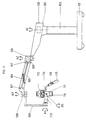
- Fig. 1 is the arrangement of a surgical microscope on one Floor stand shown.
- the tripod is on one Base part or foot 101, which generally with rollers for Procedure is equipped.
- the base part 101 also designed for ceiling or wall mounting his.
- a column 102 is attached to this base part 101, the attached fixed arm 103 rotates about its axis A1 leaves. It has a joint that can be rotated about axis A2 a parallelogram arm 105 is attached.
- the height adjustment of the Microscope connector 108 on the parallelogram 105 is with a Weight balanced gas spring or a spring assembly 106.
- the microscope consists of a microscope body 111, the insight 112 and the lens 116 and is with the arms 110 and 109 rotatable about the axis A3 at the microscope connection of the stand attached. It can be rotated around axes A1, A2 and A3 as well as the weight-balanced height adjustment with the parallelogram arm 105 in the mechanically predetermined Space except for frictional resistances free from the influence of gravity move.
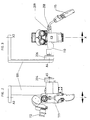
- Microscope 111 with the servo drive 204 around the axis A5 rotatable This corresponds to a rotation in the field of view from the side Direction (X direction). Together with the arm 110 can the microscope 111 is rotated about the axis A4 by the servo drive 206 become. This corresponds to a movement in the field of view up / down (Y direction).
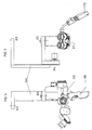
- the arrangement is in a similar representation as shown in FIGS. 2 and 3, the microscope 111 however, is rotated about the axis A4 by 90 °, so that the lens axis is horizontal.
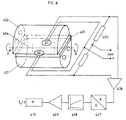
- a force and torque sensor is shown schematically and by way of example in FIG. 6 shown for the Y adjustment.
- Between Bodies 401 and 402 are stretched an elastic plate 403.
- Two pressure sensors S1 and S2 are arranged therein. If there is a moment M between the two bodies 401 and 402 Comes into effect, the result is in the elastic plate 403 intensified on both sides of a neutral phase 404 and weakened compressive forces in sensors S1 and S2 Cause changes in resistance.
- the further processing of the Signals are made with the bridge circuit 405, the amplifier 406, the analog / digital converter 407, control engineering processing 408 and a driver 409 for stepper motor 410 for servo adjustment of the A4 axis.
Landscapes
- Engineering & Computer Science (AREA)
- General Engineering & Computer Science (AREA)
- Health & Medical Sciences (AREA)
- Mechanical Engineering (AREA)
- Life Sciences & Earth Sciences (AREA)
- Surgery (AREA)
- Molecular Biology (AREA)
- Animal Behavior & Ethology (AREA)
- Oral & Maxillofacial Surgery (AREA)
- Pathology (AREA)
- Veterinary Medicine (AREA)
- Public Health (AREA)
- Biomedical Technology (AREA)
- Heart & Thoracic Surgery (AREA)
- Medical Informatics (AREA)
- Physics & Mathematics (AREA)
- Nuclear Medicine, Radiotherapy & Molecular Imaging (AREA)
- General Health & Medical Sciences (AREA)
- General Physics & Mathematics (AREA)
- Optics & Photonics (AREA)
- Microscoopes, Condenser (AREA)
Abstract
Description
Die Erfindung betrifft ein Operationsmikroskop mit einem Stativ, wobei das Mikroskop insgesamt bis zu sechs Freiheitsgrade aufweist und über Elemente des Stativs an der Mikroskopaufhängung befestigt ist, wobei das Stativ zwei vertikale Schwenkachsen, die keinem Einfluß durch Schwerkraft unterworfen sind, und für die Höhenverstellung ein Parallelogrammgestänge mit Gewichtsausgleich aufweist, die mit leichtgängiger Beweglichkeit und mit Bremsen für die Arretierung ausgebildet sind.The invention relates to a surgical microscope with a stand, with the microscope up to a total of six degrees of freedom has and about elements of the tripod on the microscope suspension is attached, the tripod two vertical Swivel axes that are not subject to gravity and a parallelogram linkage for height adjustment with weight balance, which with smooth running Agility and trained with brakes for locking are.
Bei einem solchen Stativ (US 5,213,293 A) kann das Mikroskop mit Hilfe des Stativs in die für die Operation gewünschte Stellung gebracht werden. Es weist einen Gewichtsausgleich auf, so daß es auch bei schwach gebremsten Gelenken in dieser Stellung verbleibt. Es ist aber sehr aufwendig, diesen Gewichtsausgleich zu bewirken. Eine anschließende Verstellung des Mikroskops, um das Bildfeld zu ändern, muß per Hand erfolgen.With such a tripod (US 5,213,293 A), the microscope with the help of the tripod into the desired one for the operation Position. It has a weight balance on, so that even with weakly braked joints in this Position remains. But it is very expensive to do this weight balancing to effect. A subsequent adjustment of the microscope to change the field of view must be done by hand.
Bei einem anderen bekannten Mikroskop (US 5,332,181) findet die Verstellung um alle Achsen motorisch statt. Dazu ist nur ein grober Gewichtsausgleich erforderlich, was selbstverständlich leichter zu bewirken ist, als der feine Ausgleich der erstgenannten Anordnung. Das Problem bei der Einstellung des Mikroskops auf eine neue Aufgabe bzw. neue Bedingungen erfolgt durch die Motoren nur sehr langsam, da schnelle automatische Bewegungen um die einzelnen Freiheitsgrade zu große Motoren erfordern würden und insbesondere auch gefährlich sind. Der Operateur muß daher sehr lange warten, bis die von ihm gewünschte Einstellung erreicht worden ist. Dadurch wird der Vorteil, daß nur eine grobe Ausbalancierung erforderlich ist, zunichte gemacht.In another known microscope (US 5,332,181) the adjustment around all axes by motor. This is only a rough balance is required, which goes without saying is easier to achieve than the fine balance the former arrangement. The problem with hiring the microscope for a new task or new conditions is done very slowly by the motors because fast automatic Movements too large for the individual degrees of freedom Engines would require and especially dangerous are. The surgeon must therefore wait a very long time for the desired setting has been achieved. This will the advantage that only a rough balance is required is nullified.
Zur manuellen Handhebung eines OP-Mikroskops an einem Stativ ist eine Ausbalancierung immer erforderlich. Es ist nicht nur ein Gewichtsausgleich durch Gegengewichte, Federn und Gasfedern notwendig, da die Arme des Stativs ein gewisses Gewicht haben, das natürlich immer den gleichen Wert hat. Bei Verstellungen an Zubehörteilen des Mikroskops, die bei der Ausführung von Operationen notwendig werden, verschiebt sich aber der Schwerpunkt am Mikroskop. Es muß dann eine erneute Gewichtskompensation um die Drehachsen vorgenommen werden. Der mechanische Aufwand bei mehreren Drehachsen ist unter Berücksichtigung der notwendigen Steifigkeit der Mikroskopaufhängung erheblich und wird durch motorische Antriebe noch erhöht, wenn man dem Anwender die Gewichtskompensation erleichtern will. Es sind sogar Ausführungen bekannt (DE 4320443 A, DE 43 34 069 A), bei denen die Gewichtskompensation mit Sensoren, Reglern und Stellgliedern auf Abruf automatisch durchgeführt werden.For manual lifting of an operating microscope on a tripod balancing is always necessary. It is not just a counterbalance by means of counterweights, springs and gas springs necessary because the arms of the tripod have a certain weight have, of course, always the same value. With adjustments on microscope accessories that are included in the execution of operations become necessary shifts but the focus on the microscope. Then there must be another Weight compensation can be made around the axes of rotation. The mechanical effort for several axes of rotation is taken into account the necessary rigidity of the microscope suspension considerably and is further increased by motor drives, if you make weight compensation easier for the user want. There are even known designs (DE 4320443 A, DE 43 34 069 A), in which the weight compensation with sensors, Controllers and actuators carried out automatically on demand become.
Die Aufgabe der Erfindung besteht in der Schaffung eines Mikroskops mit einem Stativ, bei dem die Einstellung des Ortes des Mikroskops schnell von Hand vorgenommen werden kann, anschließend aber eine Feineinstellung des beobachtbaren Bildfeldes vorgenommen werden kann, ohne daß diese Handhabung durch Schwerkräfte oder dadurch verursachte Momente gestört wird.The object of the invention is to create a microscope with a tripod where the setting of the place of the microscope can be done quickly by hand, then but a fine adjustment of the observable field of view can be made without this handling disturbed by gravity or moments caused by it becomes.
Die erfindungsgemäße Lösung besteht darin, daß das Mikroskop über eine dritte vertikale Achse, die keinem Einfluß durch Schwerkraft unterworfen ist, eine erste weitere dazu senkrechte Achse und eine zweite weitere zur ersten weiteren senkrechte Achse am Stativ gelagert ist, wobei die weiteren Achsen im wesentlichen senkrecht zur optischen Achse des Mikroskopobjektivs und motorisch verstellbar ausgebildet sind und die dem Mikroskop nähere weitere Achse eine seitliche Schwenkung der Blickrichtung (X-Richtung) ermöglicht und die zwischen der dritten vertikalen Achse und der dem Mikroskop näheren weiteren Achse angeordnete weitere Achse eine Schwenkung der Blickrichtung vor/zurück oder nach oben/unten (Y-Richtung) ermöglicht.The solution according to the invention is that the microscope over a third vertical axis that is unaffected by Subjected to gravity, a first further perpendicular to it Axis and a second further to the first further vertical axis is mounted on the tripod, the others Axes essentially perpendicular to the optical axis of the microscope objective and are motor-adjustable and the further axis closer to the microscope is a lateral one Panning the viewing direction (X direction) enables and between the third vertical axis and that of the microscope closer axis arranged further axis a pivot the direction of view forwards / backwards or upwards / downwards (Y direction) enables.
Es ist zwar bekannt, die Beweglichkeit von Operationsmikroskopen an Trägereinheiten mit Tasten an Handgriffen freizuschalten, die am Mikroskop angeordnet sind. Bei Betätigung der Tasten werden elektromotorische Bremsen der Stativgelenke gelöst. Die Erfindung erschöpft sich aber nicht darin, daß die Bewegung um diese Achsen schnell von Hand vorgenommen werden kann und dann die Achsen in dieser Stellung blockiert werden können. Die Erfindung zeichnet sich vielmehr durch eine Kombination dieser Verstellmöglichkeit von Hand mit einer motorischen Einstellung aus.The mobility of surgical microscopes is known on carrier units with buttons on handles, which are arranged on the microscope. When actuated the buttons become electromotive brakes on the tripod joints solved. The invention is not limited to the fact that the movement around these axes is done quickly by hand can be blocked and then the axes in this position can be. The invention is rather characterized by a Combination of this adjustment by hand with a motor adjustment.
Die größeren Verstellwege des Stativs werden dem Anwender/Operateur in an sich bekannter Weise gewichtsausgeglichen im sogenannten "free floating modus" freigegeben. Er führt das Gerät an einem Handgriff bspw. mit einer integrierten Taste, mit der die Bewegung freigegeben werden kann. Dabei ist ein feiner Gewichtsausgleich am Parallelogrammarm vorgenommen worden. Dieser Gesamtgewichtsausgleich muß möglichst genau sein, so daß für die Einstellungen nur sehr geringe Kräfte erforderlich sind. Ein Ungleichgewicht an den beiden direkt am Mikroskop vorhandenen Einstellachsen stört dann nicht, wenn bei diesen Achsen eine motorische Verstellung vorgesehen ist und die Motoren kräftig genug sind, die entsprechenden Kräfte des Ungleichgewichts aufzunehmen.The larger adjustment ranges of the tripod become the user / surgeon Weight balanced in a manner known per se released in the so-called "free floating mode". He leads the device on a handle, for example with an integrated button, with which the movement can be released. It is a fine weight balance on the parallelogram arm been. This total weight balance must be as accurate as possible be so that only very small forces for the settings required are. An imbalance in the two directly adjustment axes on the microscope do not interfere, if motorized adjustment is provided for these axes and the motors are powerful enough, the corresponding ones Absorb the forces of imbalance.
Durch die Drehungen um die dritte vertikale Achse sowie die beiden weiteren Achsen kann der Operateur das Blickfeld an die Erfordernisse anpassen. Durch die besondere Reihenfolge der beiden weiteren Achsen ist dabei eine sehr zweckmäßige Verstellbarkeit für unterschiedliche Operationsbedingungen gegeben. Die optische Achse des Operationsmikroskops wird nämlich für unterschiedliche Operationen (z. B. Gehirnoperationen, Rückenmarkoperationen, Augenoperationen) völlig unterschiedlich zur Vertikalen ausgerichtet. Wählt man die Reihenfolge der weiteren Achse anders, so ist diese günstige Veränderung des Blickfeldes nicht mehr möglich.Through the rotations around the third vertical axis as well as the The operator can see the other two axes adjust the requirements. Because of the special order the other two axes are very useful Adjustability for different operating conditions given. The optical axis of the surgical microscope is namely for different operations (e.g. brain operations, Spinal cord surgery, eye surgery) completely different aligned to the vertical. If you choose the order the other axis is different, so this is cheap Changing the field of vision is no longer possible.
Zweckmäßigerweise sind die motorischen Antriebe als Servoantriebe ausgebildet. Die Vorgabe für diese Servofunktionen erfolgt in bevorzugter Weise von elektrischen Kraft- oder Momentensensoren zwischen dem Mikroskop und dem Bedienungselement für die entsprechenden Richtungen. Die Sensoren sind so ausgeführt, daß sie ein vom Benutzer mit dem am Bedienungselement um eine Achse ausgeübtes Moment steigendes und bei Richtungswechsel im Vorzeichen wechselndes Signal abgeben. Zweckmäßigerweise sind die Bedienungselemente verstellbar, so daß der Benutzer sie in die für ihn bequemste Lage verstellen kann, ohne daß dabei die Lage der Sensoren zum Mikroskop und damit der Bezug zwischen den Signalen und Wirkrichtung verändert wird.The motor drives are expediently used as servo drives educated. These servo functions are specified preferably from electrical force or moment sensors between the microscope and the control element for the corresponding directions. The sensors are like this executed that they are one by the user with the on the control element moment exerted around an axis rising and at Give change of direction in the sign changing signal. The controls are expediently adjustable, so that the user adjust them to the most convenient position for them can without the position of the sensors to the microscope and so that the relationship between the signals and direction of action changes becomes.
Bei Längs- und Querkräften und bei Momenten senkrecht zur Sensorachse wird kein Signal abgegeben. Bei einer besonders zwechmäßigen Ausführungsform sind die Sensoren paarweise so angeordnet, daß, wenn durch eine von einer Bedienungsperson auf das Bedienungselement ausgeübte Kraft der eine Sensor entlastet wird, der andere belastet wird. Beide Sensoren sind bezüglich des zu detektierenden Moments bzw. der zu detektierenden Kraft beiderseits einer neutralen Linie angeordnet. Beide Sensorelemente stehen unter einem Druck und sind in einer Brückenschaltung gegeneinander geschaltet, so daß sich die Signale durch den Druck gegenseitig aufheben. Wird ein Moment oder eine Kraft in das Bedienungselement eingeleitet, das bzw. die eine Drehung um diese Linie zu bewirken versucht, entsteht auf der einen Seite der neutralen Linie steigender Druck, auf der anderen Seite fallender Druck. Entsprechend wird die Brücke verstimmt und liefert ein dem Moment entsprechendes Ausgangssignal. Als Sensoren können Piezoelemente, induktive Sensoren, kapazitive Aufnehmer, resistive und optische Kraft/Wegaufnehmer verwendet werden. With longitudinal and transverse forces and with moments perpendicular to No signal is emitted from the sensor axis. With one particularly two embodiment, the sensors are in pairs arranged that when by an operator force exerted on the control element by a sensor is relieved, the other is burdened. Both sensors are with regard to the torque to be detected or the one to be detected Force arranged on both sides of a neutral line. Both sensor elements are under pressure and are in one Bridge circuit switched against each other, so that the signals cancel each other out by the pressure. Becomes a Moment or force is introduced into the control element, that tries to make a rotation around this line, arises on one side of the neutral line increasing Pressure, falling pressure on the other side. Corresponding the bridge becomes out of tune and delivers the moment corresponding output signal. Piezo elements, inductive sensors, capacitive sensors, resistive and optical force / displacement transducers can be used.
Die Signale werden steuerungstechnisch weiterverarbeitet, um über Motortreiber und Servomotoren die Verstellungen vorzunehmen. Bei einer ausreichenden Dynamik der beiden Servosteuerungen zusammen mit dem "free floating" der anderen vier Freiheitsgrade werden die Einstellzeiten verkleinert. Während der Anwender das Mikroskop in den vier zur Bewegung freigegebenen Freiheitsgraden verstellt, wirken gleichzeitig die zur Richtungseinstellung der Mikroskopachse eingeleiteten Momente am Bedienungselement und bewirken mit den Servosteuerungen die entsprechende Verstellung. Durch die synchrone freie Verstellung des Mikroskops mit größeren Wegen und den Servonachlauf der kleinen Drehbewegungen entfällt der von reinen Servosystemen bekannte Effekt, daß der Anwender lange warten muß, bis die Verstellung beendet ist.The signals are processed in order to control make the adjustments via motor drivers and servomotors. With sufficient dynamics of the two servo controls together with the "free floating" of the others The response times are reduced by four degrees of freedom. While the user uses the microscope in the four to move released degrees of freedom act simultaneously those initiated for setting the direction of the microscope axis Moments on the control element and effect with the servo controls the corresponding adjustment. Through the synchronous free adjustment of the microscope with larger paths and the The servo overrun of the small rotary movements is no longer necessary pure servo systems known effect that the user long must wait until the adjustment is finished.
Zweckmäßigerweise ist die Anordnung so getroffen, daß die möglichen Bewegungen um die einzelnen Achsen bzw. Freiheitsgrade so begrenzt sind, daß das Mikroskop nicht gegen Teile des Stativs anstoßen kann.The arrangement is expediently such that the possible movements around the individual axes or degrees of freedom are so limited that the microscope cannot hit parts of the tripod.
Die Erfindung wird im folgenden anhand vorteilhafter Ausführungsformen unter Bezugnahme auf die beigefügten Zeichnungen beschrieben. Es zeigen:
- Fig. 1
- den prinzipiellen Aufbau des erfindungsgemäßen Stativs in einer Seitenansicht;
- Fig. 2
- in Seitenansicht das Mikroskop;
- Fig. 3
- in Frontansicht das Mikroskop;
- Fig. 4
- in ähnlicher Darstellung wie in Fig. 2 das Mikroskop, nachdem es um 90° gedreht ist;
- Fig. 5
- in ähnlicher Darstellung wie in Fig. 3 das Mikroskop, nachdem es um 90° gedreht ist; und
- Fig. 6
- den prinzipiellen Aufbau der Sensoren und elektrischen Auswertungsschaltungen.
- Fig. 1
- the basic structure of the tripod according to the invention in a side view;
- Fig. 2
- in side view the microscope;
- Fig. 3
- the microscope in front view;
- Fig. 4
- in a similar representation as in Figure 2, the microscope after it is rotated by 90 °.
- Fig. 5
- in a similar representation as in Figure 3, the microscope after it is rotated by 90 °. and
- Fig. 6
- the basic structure of the sensors and electrical evaluation circuits.
In Fig. 1 ist die Anordnung eines Operationsmikroskops an einem
Fußbodenstativ dargestellt. Das Stativ steht auf einem
Basisteil oder Fuß 101, der im allgemeinen mit Rollen zum
Verfahren ausgestattet ist. Selbstverständlich kann der Basisteil
101 auch für Decken- oder Wandbefestigung ausgebildet
sein. Auf diesem Basisteil 101 ist eine Säule 102 angebracht,
um deren Achse A1 sich der aufgesetzte feste Arm 103 drehen
läßt. Mit einem um die Achse A2 drehbaren Gelenk ist daran
ein Parallelogrammarm 105 befestigt. Die Höhenverstellung des
Mikroskopanschlusses 108 am Parallelogramm 105 ist mit einer
Gasfeder oder einem Federpaket 106 gewichtsausgeglichen.In Fig. 1 is the arrangement of a surgical microscope on one
Floor stand shown. The tripod is on one
Base part or
Das Mikroskop besteht aus einem Mikroskopkörper 111, dem Einblick
112 und dem Objektiv 116 und ist mit den Armen 110 und
109 drehbar um die Achse A3 am Mikroskopanschluß des Stativs
befestigt. Es läßt sich mit den Drehungen um die Achsen A1,
A2 und A3 sowie durch die gewichtsausgeglichene Höhenverstellung
mit dem Parallelogrammarm 105 im mechanisch vorgegebenen
Raum bis auf Reibungswiderstände frei von Schwerkrafteinfluß
bewegen.The microscope consists of a
Wie dies in den Fig. 1-3 dargestellt ist, ist das dort dargestellte
Mikroskop 111 mit dem Servoantrieb 204 um die Achse
A5 drehbar. Dies entspricht einer Drehung im Sehfeld in seitlicher
Richtung (X-Richtung). Zusammen mit dem Arm 110 kann
das Mikroskop 111 vom Servoantrieb 206 um die Achse A4 gedreht
werden. Dies entspricht einer Bewegung im Sehfeld nach
oben/unten (Y-Richtung).As shown in Figs. 1-3, that is shown there
In den Fig. 4 und 5 ist die Anordnung in ähnlicher Darstellung
wie in den Fig. 2 und 3 gezeigt, wobei das Mikroskop 111
allerdings um die Achse A4 um 90° gedreht ist, so daß die Objektivachse
waagerecht ist. 4 and 5, the arrangement is in a similar representation
as shown in FIGS. 2 and 3, the
In Fig. 6 ist schematisch und beispielhaft ein Kraft- und Momentsensor
für die Y-Verstellung dargestellt. Zwischen den
Körpern 401 und 402 ist eine elastische Platte 403 angespannt.
Darin sind zwei Drucksensoren S1 und S2 angeordnet.
Wenn zwischen den beiden Körpern 401 und 402 ein Moment M zur
Wirkung kommt, so ergeben sich in der elastischen Platte 403
auf den beiden Seiten einer neutralen Phase 404 verstärkte
und abgeschwächte Druckkräfte, die in den Sensoren S1 und S2
Widerstandsänderungen hervorrufen. Die Weiterverarbeitung der
Signale erfolgt mit der Brückenschaltung 405, dem Verstärker
406, dem Analog/Digitalwandler 407, regelungstechnischer Bearbeitung
408 und einem Treiber 409 für den Schrittmotor 410
zur Servoverstellung der Achse A4.A force and torque sensor is shown schematically and by way of example in FIG. 6
shown for the Y adjustment. Between
Wie dies erwähnt wurde, ist die Bewegung um die Achsen A1, A2
und A3 sowie diejenige des Parallelogrammgestänges 105
leichtgängig, so daß einfach eine Verstellung vorgenommen
werden kann. Arretierung findet dann durch die Bremsen 120
statt, die in Fig. 1 gestrichelt angedeutet sind. Diese Bremsen
können für die Grobverstellung gelöst werden, indem eine
entsprechende Taste 113 am Bedienungselement 115 betätigt
wird. Der Antrieb der Motoren kann direkt auf die entsprechenden
Achsen wirken. Es ist jedoch auch möglich, ein Getriebe
zwischenzuschalten, das in Fig. 6 bei 411 angedeutet
ist.As mentioned, the movement is about the axes A1, A2
and A3 and that of the
Claims (14)
Priority Applications (5)
| Application Number | Priority Date | Filing Date | Title |
|---|---|---|---|
| DE50012038T DE50012038D1 (en) | 2000-04-25 | 2000-04-25 | Tripod with a surgical microscope |
| EP00108786A EP1152182B1 (en) | 2000-04-25 | 2000-04-25 | Stand with a surgical microscope |
| AT00108786T ATE315762T1 (en) | 2000-04-25 | 2000-04-25 | TRIPOD WITH A SURGICAL MICROSCOPE |
| US09/841,338 US6471165B2 (en) | 2000-04-25 | 2001-04-24 | Surgical microscope and stand assembly |
| JP2001128182A JP2001309928A (en) | 2000-04-25 | 2001-04-25 | Surgical microscope |
Applications Claiming Priority (1)
| Application Number | Priority Date | Filing Date | Title |
|---|---|---|---|
| EP00108786A EP1152182B1 (en) | 2000-04-25 | 2000-04-25 | Stand with a surgical microscope |
Publications (2)
| Publication Number | Publication Date |
|---|---|
| EP1152182A1 true EP1152182A1 (en) | 2001-11-07 |
| EP1152182B1 EP1152182B1 (en) | 2006-01-11 |
Family
ID=8168548
Family Applications (1)
| Application Number | Title | Priority Date | Filing Date |
|---|---|---|---|
| EP00108786A Expired - Lifetime EP1152182B1 (en) | 2000-04-25 | 2000-04-25 | Stand with a surgical microscope |
Country Status (5)
| Country | Link |
|---|---|
| US (1) | US6471165B2 (en) |
| EP (1) | EP1152182B1 (en) |
| JP (1) | JP2001309928A (en) |
| AT (1) | ATE315762T1 (en) |
| DE (1) | DE50012038D1 (en) |
Cited By (10)
| Publication number | Priority date | Publication date | Assignee | Title |
|---|---|---|---|---|
| US4663375A (en) * | 1984-05-15 | 1987-05-05 | Mitsubishi Petrochemical Co., Ltd. | Process for producing heat-resisting moldings |
| EP1958587A1 (en) * | 2007-02-13 | 2008-08-20 | University of Dundee | Holder for medicinal purposes |
| EP2495462A1 (en) * | 2011-03-01 | 2012-09-05 | Karl Storz GmbH & Co. KG | Adjustable holding device for an endoscope |
| WO2014039084A1 (en) * | 2012-09-05 | 2014-03-13 | Raytheon Company | Optical switching assembly with over-center lock |
| DE102004008381B4 (en) * | 2003-06-30 | 2014-09-25 | Carl Zeiss Meditec Ag | Holding device, in particular for a medical-optical instrument, with means for compensating a load torque and a method for setting a state of equilibrium in a holding device |
| EP2853798A1 (en) * | 2013-09-25 | 2015-04-01 | Brunson Instrument Company | Four bar linkage imaging stand assembly system and method |
| DE102004063606B4 (en) * | 2004-02-20 | 2015-10-22 | Carl Zeiss Meditec Ag | Holding device, in particular for a medical-optical instrument, with a device for active vibration damping |
| DE102016200214A1 (en) * | 2016-01-11 | 2017-07-13 | Carl Zeiss Meditec Ag | Tripod and method for torque compensation |
| WO2017182341A1 (en) * | 2016-04-19 | 2017-10-26 | Carl Zeiss Meditec Ag | Ophthalmologic examining and/or therapeutic device having articulated arms that can be coupled |
| DE102005031557B4 (en) | 2005-07-06 | 2021-08-05 | Carl Zeiss Meditec Ag | Surgical microscope carrier system |
Families Citing this family (70)
| Publication number | Priority date | Publication date | Assignee | Title |
|---|---|---|---|---|
| US20040189847A1 (en) * | 2000-03-08 | 2004-09-30 | Dazor Manufacturing Corp. | Video magnification inspection system |
| USD503732S1 (en) * | 2003-07-31 | 2005-04-05 | Dazor Manufacturing Corp. | Video magnification system |
| US20030101677A1 (en) * | 2000-07-12 | 2003-06-05 | Hewett Frank W. | Joining system for tubular members |
| EP1191379B1 (en) * | 2000-09-22 | 2008-03-19 | Leica Microsystems Schweiz AG | Microscope with a handle particularly handle for a microscope |
| DE50111444D1 (en) * | 2000-09-28 | 2006-12-28 | Leica Microsystems Schweiz Ag | tripod |
| DE10133018A1 (en) * | 2001-07-06 | 2003-01-16 | Leica Mikroskopie Systeme Ag H | tripod |
| ES2256529T3 (en) * | 2001-10-03 | 2006-07-16 | Steris, Inc. | QUICK VIDEO / DATA CONNECTION SYSTEM FOR MONITOR SUSPENSION ARMS. |
| EP1326115B1 (en) * | 2002-01-04 | 2007-02-21 | Leica Microsystems (Schweiz) AG | Stand with an automatic balancing device |
| DE10300620B4 (en) * | 2002-05-18 | 2017-04-13 | Carl Zeiss Meditec Ag | Carrier device for a medical-optical device |
| US7207531B2 (en) * | 2002-12-17 | 2007-04-24 | Piontkowski Paul K | Head manipulable binocular microscope support |
| JP4270889B2 (en) * | 2003-01-15 | 2009-06-03 | オリンパス株式会社 | Medical instrument holding device |
| US7170250B2 (en) * | 2003-06-30 | 2007-01-30 | Carl Zeiss Surgical Gmbh | Holding arrangement having a device for actively damping vibration |
| US7109678B2 (en) * | 2003-06-30 | 2006-09-19 | Carl-Zeiss-Stiftung | Holding arrangement having an apparatus for balancing a load torque |
| KR20060057603A (en) * | 2003-08-06 | 2006-05-26 | 인테스트 코포레이션 | Test Head Positioning System |
| US20050052531A1 (en) * | 2003-09-04 | 2005-03-10 | Chapman/Leonard Studio Equipment | Stabilized camera platform system |
| US7849978B2 (en) * | 2003-10-13 | 2010-12-14 | Hill-Rom Services, Inc. | Brake system for patient care equipment support arm |
| JP4486381B2 (en) * | 2004-02-27 | 2010-06-23 | 株式会社コーナン・メディカル | Microscope arm for otolaryngological examination equipment |
| US7420731B2 (en) * | 2004-12-14 | 2008-09-02 | Piontkowski Paul K | Surgical microscope support system |
| US7770247B2 (en) * | 2005-05-02 | 2010-08-10 | Hill-Rom Services, Inc. | Brake system for wall arm |
| US7364127B2 (en) * | 2005-06-07 | 2008-04-29 | Ming-Hua Huang | Support arm for a monitor |
| DE102007009543A1 (en) * | 2007-02-27 | 2008-08-28 | Leica Microsystems (Schweiz) Ag | Microscope device with position detection |
| US8025078B2 (en) * | 2008-04-29 | 2011-09-27 | Illinois Tool Works Inc. | Vehicle mountable arm for valve operating machine |
| DE102008059331B4 (en) * | 2008-11-27 | 2012-05-31 | Siemens Aktiengesellschaft | Tripod, especially ground stand |
| KR20120030358A (en) * | 2009-05-14 | 2012-03-28 | 웨스팅하우스 일렉트릭 컴퍼니 엘엘씨 | Tetherless tube inspection system |
| USD634344S1 (en) * | 2009-06-26 | 2011-03-15 | Carl Zeiss Surgical Gmbh | Combination of a stand and an assembly connected thereto of an XY-coupling supporting a carrier arm holding a housing containing one or two microscope bodies equipped with oculars |
| USD649992S1 (en) | 2009-12-22 | 2011-12-06 | Carl Zeiss Meditec Ag | Stand for microscope assembly |
| DE102010010133A1 (en) * | 2010-03-04 | 2011-09-08 | Leica Microsystems (Schweiz) Ag | Tripod for a microscope, in particular for a surgical microscope |
| US9392931B2 (en) * | 2010-03-22 | 2016-07-19 | Brainlab Ag | Controlling a surgical microscope |
| TW201200316A (en) * | 2010-06-21 | 2012-01-01 | Univ Nat Taiwan | Sustaining manipulator arm |
| US8922884B2 (en) | 2010-10-07 | 2014-12-30 | Global Surgical Corporation | Flexible objective lens assembly and microscope |
| US8851121B2 (en) | 2010-12-06 | 2014-10-07 | Illlinois Tool Works Inc. | Torque multiplier for valve turning machine |
| DE102011003589B4 (en) * | 2011-02-03 | 2017-10-26 | Carl Zeiss Meditec Ag | Tripod for a medical device |
| US8960632B2 (en) | 2011-07-05 | 2015-02-24 | Mediamounts, Ltd. | Dual bar linkage monitor support with adustment feature |
| US8584994B2 (en) * | 2011-10-21 | 2013-11-19 | Endure Medical, Inc. | Floor stand with angled arm for microscope |
| USD685405S1 (en) * | 2011-10-21 | 2013-07-02 | Endure Medical, Inc. | Floor stand with angled arm for microscope |
| DE102012209594B3 (en) * | 2012-06-06 | 2013-06-06 | Leica Microsystems (Schweiz) Ag | Stand for e.g. spatial positioning of surgical microscope, has actuator comprising set of pivot bearings that is smaller than or equal to set of pivot bearings of another actuator, where pivot bearings are pivotable at pivot axes |
| US9487100B2 (en) * | 2012-09-14 | 2016-11-08 | General Electric Company | Electrical vehicle charging device having a brake to prevent extension and retraction of the power conduit |
| DE102013016369A1 (en) * | 2013-09-30 | 2015-04-02 | Karl Kaps Gmbh & Co. Kg | Adjustable tripod for an optical observation device |
| WO2015142930A1 (en) * | 2014-03-17 | 2015-09-24 | Intuitive Surgical Operations, Inc. | System and method for breakaway clutching in an articulated arm |
| USD836692S1 (en) * | 2014-06-30 | 2018-12-25 | Carl Zeiss Meditec Ag | Surgical microscope |
| USD836693S1 (en) * | 2014-06-30 | 2018-12-25 | Carl Zeiss Meditec Ag | Stand for a surgical microscope |
| EP3175810B1 (en) * | 2014-08-01 | 2024-10-30 | Sony Olympus Medical Solutions Inc. | Medical observation device |
| EP3212148B1 (en) | 2014-10-27 | 2025-07-09 | Intuitive Surgical Operations, Inc. | System for integrated surgical table icons |
| CN115444567A (en) | 2014-10-27 | 2022-12-09 | 直观外科手术操作公司 | System and method for instrument interference compensation |
| CN111358652B (en) | 2014-10-27 | 2022-08-16 | 直观外科手术操作公司 | System and method for integrated surgical table motion |
| EP4541305A3 (en) | 2014-10-27 | 2025-07-30 | Intuitive Surgical Operations, Inc. | System and method for integrated surgical table |
| KR102476611B1 (en) | 2014-10-27 | 2022-12-12 | 인튜어티브 서지컬 오퍼레이션즈 인코포레이티드 | System and method for registering to a surgical table |
| CN107072727B (en) | 2014-10-27 | 2020-01-24 | 直观外科手术操作公司 | Medical device with active brake release control |
| KR102628659B1 (en) | 2014-10-27 | 2024-01-25 | 인튜어티브 서지컬 오퍼레이션즈 인코포레이티드 | System and method for monitoring control points during reactive motion |
| CN105982679A (en) * | 2015-02-04 | 2016-10-05 | 深圳迈瑞生物医疗电子股份有限公司 | X-ray photography system and rocker arm mechanism thereof |
| WO2016164438A1 (en) * | 2015-04-07 | 2016-10-13 | Brown Garrett W | Balancing support interface for payload stabilizers |
| US10767811B2 (en) * | 2016-02-24 | 2020-09-08 | Stryker Corporation | Brake control system for suspensions |
| US10203064B2 (en) * | 2016-04-29 | 2019-02-12 | GCX Corporation | Locking release mechanism for an articulated support arm |
| US9772497B1 (en) * | 2016-09-23 | 2017-09-26 | Robert Troy Hewlett | Customized viewing system for an optical device |
| US11864958B2 (en) | 2017-05-03 | 2024-01-09 | Lsi Solutions, Inc. | Surgical equipment holder |
| WO2018204612A1 (en) * | 2017-05-03 | 2018-11-08 | Lsi Solutions, Inc. | Surgical equipment holder |
| JP1623665S (en) * | 2018-02-13 | 2019-02-04 | ||
| CN108591791B (en) * | 2018-07-13 | 2023-06-23 | 桂林智神信息技术股份有限公司 | Frame subassembly and stabilizer for stabilizer |
| EP3826569B1 (en) * | 2018-07-25 | 2022-12-14 | American Sterilizer Company | Brake assembly for medical device support system |
| USD947919S1 (en) * | 2018-09-18 | 2022-04-05 | Carl Zeiss Meditec Ag | Stand for a surgical instrument |
| EP3693642B1 (en) | 2019-01-17 | 2022-06-15 | Illinois Tool Works, Inc. | Valve operating device having a movable arm for use in exercising valves |
| USD1010315S1 (en) | 2019-09-06 | 2024-01-09 | Carl Zeiss Meditec Ag | Surgical microscope |
| CN113040911B (en) * | 2019-12-27 | 2022-08-19 | 重庆海扶医疗科技股份有限公司 | Surgical system, surgical system control method and surgical system control method |
| CN113040905B (en) * | 2019-12-27 | 2025-06-27 | 重庆海扶医疗科技股份有限公司 | Manipulator for controlling the end effector of surgical instruments |
| USD934937S1 (en) | 2020-03-11 | 2021-11-02 | Carl Zeiss Meditec Ag | Surgical microscope |
| USD934327S1 (en) | 2020-03-11 | 2021-10-26 | Carl Zeiss Meditec Ag | Surgical microscope |
| CN111772823B (en) * | 2020-06-23 | 2021-05-11 | 苏州昊信精密机械有限公司 | Operating microscope support arm |
| CN112013217A (en) * | 2020-08-25 | 2020-12-01 | 杭州新汉杰科技有限公司 | Computer display support adjustment mechanism |
| JP2023544317A (en) * | 2020-09-30 | 2023-10-23 | オーリス ヘルス インコーポレイテッド | Guided and coordinated bed movements for intraoperative patient positioning in robotic surgery |
| WO2024180528A1 (en) * | 2023-03-02 | 2024-09-06 | Alcon Inc. | Visualization robot with ophthalmic surgery-optimized kinematics |
Citations (8)
| Publication number | Priority date | Publication date | Assignee | Title |
|---|---|---|---|---|
| US5213293A (en) | 1989-07-04 | 1993-05-25 | Leica Heerbrugg Ag | Stand equipped with accessory devices for supporting a freely orientable apparatus |
| EP0552524A1 (en) * | 1992-01-17 | 1993-07-28 | Sahara, Kesanori | Stand apparatus for medical optical instrument |
| US5273039A (en) * | 1989-10-16 | 1993-12-28 | Olympus Optical Co., Ltd. | Surgical microscope apparatus having a function to display coordinates of observation point |
| US5332181A (en) | 1992-02-01 | 1994-07-26 | Carl Zeiss-Stiftung | Motorized stand |
| DE4320443A1 (en) | 1993-06-21 | 1994-12-22 | Zeiss Carl Fa | Balanceable stand |
| DE4334069A1 (en) | 1993-06-21 | 1995-04-13 | Zeiss Carl Fa | Balanced tripod |
| EP0849053A1 (en) * | 1996-12-16 | 1998-06-24 | Kabushiki Kaisha Sankyo Seiki Seisakusho | Method of controlling force assisting device and control apparatus using the same |
| DE19732212A1 (en) * | 1997-07-26 | 1999-01-28 | Zeiss Carl Fa | Operation microscope |
Family Cites Families (9)
| Publication number | Priority date | Publication date | Assignee | Title |
|---|---|---|---|---|
| DE7930125U1 (en) * | 1979-07-24 | 1980-01-24 | Contraves Ag, Zuerich (Schweiz) | ADDITIONAL DEVICE ON A TRIPOD FOR AN OPTICAL OBSERVATION DEVICE |
| DE7930126U1 (en) * | 1979-07-24 | 1980-01-24 | Contraves Ag, Zuerich (Schweiz) | TRIPOD FOR AN OPTICAL OBSERVATION DEVICE |
| US4548373A (en) * | 1983-03-22 | 1985-10-22 | Tokyo Kogaku Kikai Kabushiki Kaisha | Medical equipment supporting device |
| JPS63296743A (en) * | 1987-05-29 | 1988-12-02 | Mitaka Koki Kk | Stand apparatus for medical optical machinery |
| US5609316A (en) * | 1995-09-05 | 1997-03-11 | Tigliev; George S. | Suspension system for surgical microscope |
| JP3022760B2 (en) * | 1996-02-26 | 2000-03-21 | 三鷹光器株式会社 | Equipment support structure for medical stand device |
| JP3377740B2 (en) * | 1996-12-16 | 2003-02-17 | 株式会社三協精機製作所 | Control method of force assist device and control device using this method |
| JP4083316B2 (en) * | 1998-10-01 | 2008-04-30 | オリンパス株式会社 | Surgical microscope |
| EP1067419B1 (en) * | 1999-07-03 | 2008-01-30 | Leica Microsystems AG | Ceiling mount |
-
2000
- 2000-04-25 EP EP00108786A patent/EP1152182B1/en not_active Expired - Lifetime
- 2000-04-25 DE DE50012038T patent/DE50012038D1/en not_active Expired - Lifetime
- 2000-04-25 AT AT00108786T patent/ATE315762T1/en not_active IP Right Cessation
-
2001
- 2001-04-24 US US09/841,338 patent/US6471165B2/en not_active Expired - Lifetime
- 2001-04-25 JP JP2001128182A patent/JP2001309928A/en active Pending
Patent Citations (8)
| Publication number | Priority date | Publication date | Assignee | Title |
|---|---|---|---|---|
| US5213293A (en) | 1989-07-04 | 1993-05-25 | Leica Heerbrugg Ag | Stand equipped with accessory devices for supporting a freely orientable apparatus |
| US5273039A (en) * | 1989-10-16 | 1993-12-28 | Olympus Optical Co., Ltd. | Surgical microscope apparatus having a function to display coordinates of observation point |
| EP0552524A1 (en) * | 1992-01-17 | 1993-07-28 | Sahara, Kesanori | Stand apparatus for medical optical instrument |
| US5332181A (en) | 1992-02-01 | 1994-07-26 | Carl Zeiss-Stiftung | Motorized stand |
| DE4320443A1 (en) | 1993-06-21 | 1994-12-22 | Zeiss Carl Fa | Balanceable stand |
| DE4334069A1 (en) | 1993-06-21 | 1995-04-13 | Zeiss Carl Fa | Balanced tripod |
| EP0849053A1 (en) * | 1996-12-16 | 1998-06-24 | Kabushiki Kaisha Sankyo Seiki Seisakusho | Method of controlling force assisting device and control apparatus using the same |
| DE19732212A1 (en) * | 1997-07-26 | 1999-01-28 | Zeiss Carl Fa | Operation microscope |
Cited By (14)
| Publication number | Priority date | Publication date | Assignee | Title |
|---|---|---|---|---|
| US4663375A (en) * | 1984-05-15 | 1987-05-05 | Mitsubishi Petrochemical Co., Ltd. | Process for producing heat-resisting moldings |
| DE102004008381B4 (en) * | 2003-06-30 | 2014-09-25 | Carl Zeiss Meditec Ag | Holding device, in particular for a medical-optical instrument, with means for compensating a load torque and a method for setting a state of equilibrium in a holding device |
| DE102004063606B4 (en) * | 2004-02-20 | 2015-10-22 | Carl Zeiss Meditec Ag | Holding device, in particular for a medical-optical instrument, with a device for active vibration damping |
| DE102005031557B4 (en) | 2005-07-06 | 2021-08-05 | Carl Zeiss Meditec Ag | Surgical microscope carrier system |
| EP1958587A1 (en) * | 2007-02-13 | 2008-08-20 | University of Dundee | Holder for medicinal purposes |
| US8409173B2 (en) | 2007-02-13 | 2013-04-02 | University Of Dundee | Holding device for medical purposes |
| US8870141B2 (en) | 2011-03-01 | 2014-10-28 | Karl Storz Gmbh & Co. Kg | Adjustable holding apparatus for an endoscope |
| EP2495462A1 (en) * | 2011-03-01 | 2012-09-05 | Karl Storz GmbH & Co. KG | Adjustable holding device for an endoscope |
| WO2014039084A1 (en) * | 2012-09-05 | 2014-03-13 | Raytheon Company | Optical switching assembly with over-center lock |
| EP2853798A1 (en) * | 2013-09-25 | 2015-04-01 | Brunson Instrument Company | Four bar linkage imaging stand assembly system and method |
| US10082240B2 (en) | 2013-09-25 | 2018-09-25 | Brunson Instrument Company | Four bar linkage imaging stand assembly system and method |
| DE102016200214A1 (en) * | 2016-01-11 | 2017-07-13 | Carl Zeiss Meditec Ag | Tripod and method for torque compensation |
| DE102016200214B4 (en) * | 2016-01-11 | 2021-06-10 | Carl Zeiss Meditec Ag | Stand and procedure for torque compensation |
| WO2017182341A1 (en) * | 2016-04-19 | 2017-10-26 | Carl Zeiss Meditec Ag | Ophthalmologic examining and/or therapeutic device having articulated arms that can be coupled |
Also Published As
| Publication number | Publication date |
|---|---|
| EP1152182B1 (en) | 2006-01-11 |
| JP2001309928A (en) | 2001-11-06 |
| ATE315762T1 (en) | 2006-02-15 |
| US6471165B2 (en) | 2002-10-29 |
| DE50012038D1 (en) | 2006-04-06 |
| US20020014562A1 (en) | 2002-02-07 |
Similar Documents
| Publication | Publication Date | Title |
|---|---|---|
| EP1152182A1 (en) | Surgical microscope | |
| DE602004012744T2 (en) | ARMREST FOR USE WITH A VEHICLE SEAT | |
| DE102008011638B4 (en) | Balancing device for surgical microscope | |
| DE3728527C2 (en) | ||
| DE602005000651T2 (en) | Weight balance mechanism for a surgical microscope | |
| DE3316460A1 (en) | Gravity-compensating device for a deflection arm | |
| DE2200848A1 (en) | SAFETY DEVICE FOR AN X-RAY EXAMINATION DEVICE WITH A SWIVELING PATIENT POSITIONING TABLE | |
| EP0476552A1 (en) | Slewing mechanism for supporting devices for optical observation instruments | |
| EP1336885B1 (en) | Microsurgical microscope system | |
| EP1336884B1 (en) | Microsurgical microscope system | |
| DE10163354A1 (en) | Device for holding an optical viewing device | |
| DE7315186U (en) | ADJUSTABLE TRIPOD FOR AN OPTICAL OBSERVATION DEVICE, IN PARTICULAR A BINOCULAR MICROSCOPE | |
| EP1185912B1 (en) | Device for controlling an apparatus | |
| WO2003081337A2 (en) | Device for manipulation of the angular position of an object relative to a fixed structure | |
| DE2640447A1 (en) | Weight compensating frame for manually held power screw driver - has support arm with universal joint and weight equaliser coupled to rear of tool | |
| DE10200845B4 (en) | Dither correction device and optical device with dither correction function | |
| CH685653A5 (en) | Stand with a mechanical control unit for an associated surgical microscope. | |
| DE102021119530B4 (en) | Surgical instrument, steering gear therefor and method for controlling the position of a steering ring of the steering gear | |
| DE3637311C2 (en) | Arrangement for adjusting the direction of a binocular microscope | |
| DE102012222578A1 (en) | surgical microscope | |
| EP1037085B1 (en) | Suspension system for surgical microscope | |
| DE10314156B9 (en) | Swivel bracket assembly and method for controlling such | |
| DE2416106C3 (en) | Device for adjusting an optical observation device | |
| CH670320A5 (en) | ||
| DE4316037A1 (en) | Adapter for positioning a medical therapeutic and/or diagnostic instrument arranged on a stand |
Legal Events
| Date | Code | Title | Description |
|---|---|---|---|
| PUAI | Public reference made under article 153(3) epc to a published international application that has entered the european phase |
Free format text: ORIGINAL CODE: 0009012 |
|
| AK | Designated contracting states |
Kind code of ref document: A1 Designated state(s): AT BE CH CY DE DK ES FI FR GB GR IE IT LI LU MC NL PT SE |
|
| AX | Request for extension of the european patent |
Free format text: AL;LT;LV;MK;RO;SI |
|
| 17P | Request for examination filed |
Effective date: 20011213 |
|
| AKX | Designation fees paid |
Free format text: AT BE CH CY DE DK ES FI FR GB GR IE IT LI LU MC NL PT SE |
|
| 17Q | First examination report despatched |
Effective date: 20041110 |
|
| GRAP | Despatch of communication of intention to grant a patent |
Free format text: ORIGINAL CODE: EPIDOSNIGR1 |
|
| RTI1 | Title (correction) |
Free format text: STAND WITH A SURGICAL MICROSCOPE |
|
| GRAS | Grant fee paid |
Free format text: ORIGINAL CODE: EPIDOSNIGR3 |
|
| GRAA | (expected) grant |
Free format text: ORIGINAL CODE: 0009210 |
|
| AK | Designated contracting states |
Kind code of ref document: B1 Designated state(s): AT BE CH CY DE DK ES FI FR GB GR IE IT LI LU MC NL PT SE |
|
| PG25 | Lapsed in a contracting state [announced via postgrant information from national office to epo] |
Ref country code: NL Free format text: LAPSE BECAUSE OF FAILURE TO SUBMIT A TRANSLATION OF THE DESCRIPTION OR TO PAY THE FEE WITHIN THE PRESCRIBED TIME-LIMIT Effective date: 20060111 Ref country code: FI Free format text: LAPSE BECAUSE OF FAILURE TO SUBMIT A TRANSLATION OF THE DESCRIPTION OR TO PAY THE FEE WITHIN THE PRESCRIBED TIME-LIMIT Effective date: 20060111 Ref country code: IE Free format text: LAPSE BECAUSE OF FAILURE TO SUBMIT A TRANSLATION OF THE DESCRIPTION OR TO PAY THE FEE WITHIN THE PRESCRIBED TIME-LIMIT Effective date: 20060111 |
|
| REG | Reference to a national code |
Ref country code: CH Ref legal event code: EP |
|
| REG | Reference to a national code |
Ref country code: IE Ref legal event code: FG4D Free format text: LANGUAGE OF EP DOCUMENT: GERMAN |
|
| REG | Reference to a national code |
Ref country code: CH Ref legal event code: NV Representative=s name: TROESCH SCHEIDEGGER WERNER AG |
|
| REF | Corresponds to: |
Ref document number: 50012038 Country of ref document: DE Date of ref document: 20060406 Kind code of ref document: P |
|
| PG25 | Lapsed in a contracting state [announced via postgrant information from national office to epo] |
Ref country code: SE Free format text: LAPSE BECAUSE OF FAILURE TO SUBMIT A TRANSLATION OF THE DESCRIPTION OR TO PAY THE FEE WITHIN THE PRESCRIBED TIME-LIMIT Effective date: 20060411 Ref country code: DK Free format text: LAPSE BECAUSE OF FAILURE TO SUBMIT A TRANSLATION OF THE DESCRIPTION OR TO PAY THE FEE WITHIN THE PRESCRIBED TIME-LIMIT Effective date: 20060411 |
|
| PG25 | Lapsed in a contracting state [announced via postgrant information from national office to epo] |
Ref country code: ES Free format text: LAPSE BECAUSE OF FAILURE TO SUBMIT A TRANSLATION OF THE DESCRIPTION OR TO PAY THE FEE WITHIN THE PRESCRIBED TIME-LIMIT Effective date: 20060422 |
|
| PG25 | Lapsed in a contracting state [announced via postgrant information from national office to epo] |
Ref country code: AT Free format text: LAPSE BECAUSE OF NON-PAYMENT OF DUE FEES Effective date: 20060425 |
|
| GBT | Gb: translation of ep patent filed (gb section 77(6)(a)/1977) |
Effective date: 20060405 |
|
| PG25 | Lapsed in a contracting state [announced via postgrant information from national office to epo] |
Ref country code: MC Free format text: LAPSE BECAUSE OF NON-PAYMENT OF DUE FEES Effective date: 20060430 Ref country code: BE Free format text: LAPSE BECAUSE OF NON-PAYMENT OF DUE FEES Effective date: 20060430 |
|
| PG25 | Lapsed in a contracting state [announced via postgrant information from national office to epo] |
Ref country code: PT Free format text: LAPSE BECAUSE OF FAILURE TO SUBMIT A TRANSLATION OF THE DESCRIPTION OR TO PAY THE FEE WITHIN THE PRESCRIBED TIME-LIMIT Effective date: 20060612 |
|
| NLV1 | Nl: lapsed or annulled due to failure to fulfill the requirements of art. 29p and 29m of the patents act | ||
| ET | Fr: translation filed | ||
| REG | Reference to a national code |
Ref country code: IE Ref legal event code: FD4D |
|
| PLBE | No opposition filed within time limit |
Free format text: ORIGINAL CODE: 0009261 |
|
| STAA | Information on the status of an ep patent application or granted ep patent |
Free format text: STATUS: NO OPPOSITION FILED WITHIN TIME LIMIT |
|
| 26N | No opposition filed |
Effective date: 20061012 |
|
| BERE | Be: lapsed |
Owner name: MOLLER-WEDEL G.M.B.H. Effective date: 20060430 |
|
| PG25 | Lapsed in a contracting state [announced via postgrant information from national office to epo] |
Ref country code: GR Free format text: LAPSE BECAUSE OF FAILURE TO SUBMIT A TRANSLATION OF THE DESCRIPTION OR TO PAY THE FEE WITHIN THE PRESCRIBED TIME-LIMIT Effective date: 20060412 |
|
| PG25 | Lapsed in a contracting state [announced via postgrant information from national office to epo] |
Ref country code: LU Free format text: LAPSE BECAUSE OF NON-PAYMENT OF DUE FEES Effective date: 20060425 |
|
| PG25 | Lapsed in a contracting state [announced via postgrant information from national office to epo] |
Ref country code: CY Free format text: LAPSE BECAUSE OF FAILURE TO SUBMIT A TRANSLATION OF THE DESCRIPTION OR TO PAY THE FEE WITHIN THE PRESCRIBED TIME-LIMIT Effective date: 20060111 |
|
| REG | Reference to a national code |
Ref country code: DE Ref legal event code: R082 Ref document number: 50012038 Country of ref document: DE Representative=s name: GLAWE DELFS MOLL PARTNERSCHAFT MBB VON PATENT-, DE |
|
| REG | Reference to a national code |
Ref country code: DE Ref legal event code: R082 Ref document number: 50012038 Country of ref document: DE Representative=s name: GLAWE DELFS MOLL PARTNERSCHAFT MBB VON PATENT-, DE Effective date: 20140211 Ref country code: DE Ref legal event code: R081 Ref document number: 50012038 Country of ref document: DE Owner name: MOELLER-WEDEL GMBH & CO. KG, DE Free format text: FORMER OWNER: MOELLER-WEDEL GMBH, 22880 WEDEL, DE Effective date: 20140211 |
|
| PGFP | Annual fee paid to national office [announced via postgrant information from national office to epo] |
Ref country code: IT Payment date: 20140428 Year of fee payment: 15 Ref country code: FR Payment date: 20140416 Year of fee payment: 15 |
|
| PGFP | Annual fee paid to national office [announced via postgrant information from national office to epo] |
Ref country code: DE Payment date: 20150623 Year of fee payment: 16 Ref country code: GB Payment date: 20150423 Year of fee payment: 16 Ref country code: CH Payment date: 20150422 Year of fee payment: 16 |
|
| PG25 | Lapsed in a contracting state [announced via postgrant information from national office to epo] |
Ref country code: IT Free format text: LAPSE BECAUSE OF NON-PAYMENT OF DUE FEES Effective date: 20150425 |
|
| REG | Reference to a national code |
Ref country code: FR Ref legal event code: ST Effective date: 20151231 |
|
| PG25 | Lapsed in a contracting state [announced via postgrant information from national office to epo] |
Ref country code: FR Free format text: LAPSE BECAUSE OF NON-PAYMENT OF DUE FEES Effective date: 20150430 |
|
| REG | Reference to a national code |
Ref country code: DE Ref legal event code: R119 Ref document number: 50012038 Country of ref document: DE |
|
| REG | Reference to a national code |
Ref country code: CH Ref legal event code: PL |
|
| GBPC | Gb: european patent ceased through non-payment of renewal fee |
Effective date: 20160425 |
|
| PG25 | Lapsed in a contracting state [announced via postgrant information from national office to epo] |
Ref country code: DE Free format text: LAPSE BECAUSE OF NON-PAYMENT OF DUE FEES Effective date: 20161101 Ref country code: GB Free format text: LAPSE BECAUSE OF NON-PAYMENT OF DUE FEES Effective date: 20160425 Ref country code: LI Free format text: LAPSE BECAUSE OF NON-PAYMENT OF DUE FEES Effective date: 20160430 Ref country code: CH Free format text: LAPSE BECAUSE OF NON-PAYMENT OF DUE FEES Effective date: 20160430 |