EP1152107A1 - Systéme a anti-piratage pour l'accès mains libres d'un véhicule automobile - Google Patents
Systéme a anti-piratage pour l'accès mains libres d'un véhicule automobile Download PDFInfo
- Publication number
- EP1152107A1 EP1152107A1 EP01400875A EP01400875A EP1152107A1 EP 1152107 A1 EP1152107 A1 EP 1152107A1 EP 01400875 A EP01400875 A EP 01400875A EP 01400875 A EP01400875 A EP 01400875A EP 1152107 A1 EP1152107 A1 EP 1152107A1
- Authority
- EP
- European Patent Office
- Prior art keywords
- signal
- vehicle
- identification device
- bit
- piracy
- Prior art date
- Legal status (The legal status is an assumption and is not a legal conclusion. Google has not performed a legal analysis and makes no representation as to the accuracy of the status listed.)
- Granted
Links
- 238000004891 communication Methods 0.000 claims abstract description 36
- 230000004044 response Effects 0.000 claims abstract description 36
- 230000005540 biological transmission Effects 0.000 claims description 14
- 238000005259 measurement Methods 0.000 claims description 5
- 230000003111 delayed effect Effects 0.000 claims description 3
- 238000012545 processing Methods 0.000 claims description 3
- 230000002457 bidirectional effect Effects 0.000 claims description 2
- 230000015654 memory Effects 0.000 description 14
- 230000006870 function Effects 0.000 description 12
- 238000010586 diagram Methods 0.000 description 10
- 238000000034 method Methods 0.000 description 3
- 239000000203 mixture Substances 0.000 description 3
- 238000004904 shortening Methods 0.000 description 3
- 230000008054 signal transmission Effects 0.000 description 3
- 230000033228 biological regulation Effects 0.000 description 2
- 230000004913 activation Effects 0.000 description 1
- 230000003466 anti-cipated effect Effects 0.000 description 1
- 238000013459 approach Methods 0.000 description 1
- 230000001934 delay Effects 0.000 description 1
- 238000003708 edge detection Methods 0.000 description 1
- 230000006698 induction Effects 0.000 description 1
- 238000012423 maintenance Methods 0.000 description 1
- 244000045947 parasite Species 0.000 description 1
- 238000003825 pressing Methods 0.000 description 1
- 230000008569 process Effects 0.000 description 1
Images



Classifications
-
- G—PHYSICS
- G07—CHECKING-DEVICES
- G07C—TIME OR ATTENDANCE REGISTERS; REGISTERING OR INDICATING THE WORKING OF MACHINES; GENERATING RANDOM NUMBERS; VOTING OR LOTTERY APPARATUS; ARRANGEMENTS, SYSTEMS OR APPARATUS FOR CHECKING NOT PROVIDED FOR ELSEWHERE
- G07C9/00—Individual registration on entry or exit
- G07C9/00174—Electronically operated locks; Circuits therefor; Nonmechanical keys therefor, e.g. passive or active electrical keys or other data carriers without mechanical keys
- G07C9/00309—Electronically operated locks; Circuits therefor; Nonmechanical keys therefor, e.g. passive or active electrical keys or other data carriers without mechanical keys operated with bidirectional data transmission between data carrier and locks
Definitions
- the present invention relates to a so-called hand access system free for motor vehicle, i.e. a system of wireless communication allowing entry into the vehicle without key.
- This system can also be applied to hands-free starting of the vehicle, i.e. when starting without a key.
- Such a system generally includes a device identification intended to be worn by a user and capable of establishing wireless two-way remote communication with a unit control unit on board the vehicle to authenticate the user and order locking means / unlocking the door locks when the user has been recognized as authentic.
- Communication protocol initialization can be activated by operating the exterior door handle, to hands-free access, or by pressing a start button, in hands-free start mode.
- the system is able to establish said two-way communication when the identification device is located at a distance less than a predetermined limit distance from the vehicle, generally of the order of a few meters, to avoid, on the one hand, interference with other signal sources from the environment, and, on the other hand, to avoid the functioning of the system at a distance such that the user is too far from the vehicle to be aware of the operations carried out by said system.
- a such a system allows communication only at very short distance from the vehicle in the order of a few cm.
- Another commonly used system proposed is to use low frequency carrier waves, around 125 kHz for communication from the vehicle to the identification device, and ultra high carrier waves frequency, for example of the order of 434 or 868 MHz, for the area Europe, and 315 or 902 MHz for the USA zone.
- the identification device must include a battery to power its own electronic circuits. To minimize consumption electric, we can provide, for example, that the device identification is dormant for 9 ms and awake 1 ms, during periods of 10 ms.
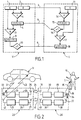
- FIG. 1 of the accompanying drawings there is shown a example of an already known encryption system.
- a vehicle V which comprises in its central unit a memory 1 containing a secret key K and a number generator 2, the generated random numbers R having, for example, a length of 56 bits.
- This random number R is transmitted towards the identification device I, as indicated by arrow 3.
- this same random number R is mixed with the key secret K following a complex associative function f, in a mixer 4 which is connected to its input to memory 1 and to the generator of random numbers 2.
- Mixer 4 outputs a signal representative of the mixture of the secret key K and the random number R, at know the signal f (R, K). This signal is stored in a memory 5 connected to the output of mixer 4. This signal is sent to the device of identification I, in the form of a signal of length by 28-bit example, as shown by arrow 6.
- the signal f (R, K) is mixed again with the secret key K in a mixer 7, which is connected at its input to memories 1 and 5 above.
- This mixer 7 mixes the two signals according to a function complex associative g.
- Vehicle V then stores in a memory 8 connected to the mixer output 7 the signal representative of the mixture, namely the signal g (R, f, K).
- the same secret key K is stored in a memory 11 and a mixer 14 having the same associative function f receives as input the secret key provided by the memory 11 of the identification device I and the random number R received by the identification device from the vehicle.
- the identification device I stores the signal at the mixer output 14 in a memory 15 and compare this signal in a comparator 16 with the signal received according to arrow 6 from vehicle V. If the two signals are not identical, subject to the time of hardware and signal transmission delay in the area of authorized transmission, the identification device interrupts the communication as unauthorized. On the other hand, if the two signals match, the signal is mixed in a mixer 17 with the secret key provided by memory 11 of the device identification I, following the same associative function g above.
- the mixer 17 output signal is stored in memory 18 of the identification device to then be sent to the vehicle according to arrow 9 in the form of a signal having a length by 20 bit example.
- the signal received by arrow 9 is compared with the signal received from the vehicle memory 8 in a comparator 10. If these two signals match, subject to delays due to hardware response time and signal transmission in the authorized zone, the rest of the communication is authorized and the unit vehicle center may, if necessary, order the condemnation or unlocking of the door locks of the vehicle.
- another encryption protocol could be used to secure data transmission.
- This signal 21 sent by the vehicle is received by a coil 22 of the relay box 20, which is connected to a receiver 23 at 125 kHz.
- This receiver 23 is connected to a transmitter at broadband at high frequency, of the order of several MHz.
- the transmitter 24 transmits via its antenna 25, as represented by the arrow 26, to a second relay box 30, which is carried by another pirate which closely follows user U.
- the exchange of information between the two relay boxes 20 and 30 being carried out at very high frequency, it is possible to make this communication from a long distance.
- the second relay box 30 includes an antenna 31 for receiving the signal 26 emitted by the relay box 20.
- the antenna 31 is connected to a broadband receiver at the same frequency as transmitter 24 of the first relay box 20.
- the signal thus received is retransmitted at low frequency at 125 kHz by a transmitter 33 which is connected to a coil 34 to send a signal 35 to the device identification I which conforms to signal 21 emitted by the vehicle.
- the signal 35 being the repetition of the authentic signal of the vehicle, the identification device I will recognize it and in turn issue its response signal 36, said response signal 36 being sent at high frequency and received by an antenna 37 of the second relay box 30, by example at 434 MHz.
- the antenna 37 is connected to a receiver 38, which goes convert the signal at 434 MHz to a signal at a different frequency, for example at 315 MHz.
- the signal is then transmitted by a transmitter at broadband 39 via an antenna 40 to the first relay box 20, this difference in frequency being necessary for the different signals do not interfere with each other.
- the frequency of signal 41 sent back by the second relay box 30 is different both the frequency of signal 26 and signal 36.
- This signal 41 is received by an antenna 27 of the first relay box 20, said antenna 27 being connected to a broadband receiver 28 of the same frequency as the transmitter 39.
- the receiver 28 is connected to a transmitter 29 which transforms the 315 MHz signal into a 434 MHz signal which is sent via the antenna 42 of the first relay box 20 to the vehicle V, as represented by the zigzag arrow 43.
- the hackers use relay boxes having broadband links, for example greater than 50 MHz, which is possible because pirate systems do not have to respect regulations; additional transit time due to distance can be of the order of a few nanoseconds, which is negligible compared to the necessary time constants for normal transmission allowed.
- the total communication can be of the order of 20 to 40 ms, and the duration total operation of the system to trigger the unlocking or locking electric locks can be of the order of 100 ms.
- one solution could be to measure the propagation time of UHF radio waves, comparing this measured time with a time predetermined corresponding to a communication in an area limited allowed around the vehicle.
- a time predetermined corresponding to a communication in an area limited allowed around the vehicle For example, to detect the time delay due to distance, compared to communication time overall, it is necessary to have broad bandwidth, which corresponds to a rapid communication rate, for example of in the range of 20 to 40 Mb / s. With such a communication rate, it is necessary to operate at very high frequency, for example at 2.4 GHz. But to measure very short times, it is necessary to have a very high bandwidth, which comes up against applicable regulations that severely limit bandwidths allowed, to avoid saturation of the environment with waves electromagnetic.
- the object of the invention is to eliminate the aforementioned drawbacks and to propose a so-called hands-free access system for a motor vehicle, allowing to detect a hacking of the system, in particular by through relay boxes, taking into account the time of propagation of the signal between the vehicle and the identification device.
- the invention relates to an access system called hands free for motor vehicle, comprising a device identification intended to be worn by a user and capable of establishing wireless two-way remote communication with a unit control unit on board the vehicle to authenticate the user and order locking means / unlocking the door locks when the user has been recognized as authentic, said system being capable of establishing said two-way communication when the identification device is located at a distance less than a predetermined limit distance from the vehicle, characterized in that said central unit is able to generate, at a predetermined high clock rate, when communication, an anti-piracy bit stream, each bit of said train being transmitted to the identification device in the form of a signal radio frequency interrogation representative of said bit, so only after reception of said interrogation signal by the device identification, the latter transmits, with a delay at least equal to one useful bit time, a response signal to the central control unit, the latter comprising at least one mixer capable of mixing, on the one hand, the response signal received from the device of identification and, on the other hand, the anti-piracy
- “Useful transmission time” means the transmission time of the binary information of said bit with respect to the total time of the cell at which is associated with said bit which generally includes said time useful and a time of silence to allow reception of the signal re-emitted by the identification device during said time of silence.
- the sum of the response times performed by the integrator is stopped when the central control unit detects receiving the last bit of the anti-piracy train.
- the output of the integrator is linked to at least a second comparator to compare said sum response time with another predetermined threshold value lower than said first predetermined threshold value, beyond which communication is detected beyond said distance predetermined limit.
- the device identification includes a digital signal timer capable of delay the interrogation signal received by a useful bit time from the vehicle, a carrier wave oscillator in radio frequency, connected at output to a phase modulator or amplitude, which is controlled by the signal at the output of said retarder, for outputting said response signal to said modulator to be issued to the vehicle.
- the identification device may have a falling edge detector to detect the edge descending from the interrogation signal received from the vehicle, said detector being able to tilt said oscillator of the device of identification between a stop state corresponding to the reception mode of the identification device and a corresponding operating state to its mode of transmission.
- the anti-piracy bit stream is generated by the central processing unit after the data transmission authentication methods encrypted to the identification device.
- the identification device may include a mixer for mix the signal at the output of said self-timer with a digital signal of encrypted authentication response from the identification device, to a slower than the anti-piracy bitstream, the signal output of this mixer being able to control the aforementioned modulator of the identification device.
- the central unit of the vehicle comprises a phase or amplitude demodulator to demodulate the signal received by the vehicle from the identification device, a exclusive OR logic gate whose inputs are connected respectively said phase demodulator and a digital signal retarder, said retarder being capable of delaying by bit useful time each bit of the anti-piracy train generated by the central unit, said logic gate being able to output a digital signal representative of the encrypted identification device response signal.
- the signal delivered in output of the aforementioned exclusive OR logic gate is compared by the unit central to an encrypted digital authentication signal generated by the central unit, in order to authenticate the identification device.
- the exit from said door exclusive OR logic is connected to an input of a second door exclusive OR logic whose other input receives a digital signal encrypted authentication generated by the central unit, in order to deliver at output said signal representative of successive time offsets of every bit of the anti-piracy train.
- the central unit is able to alternately control the stop and start of the oscillator the central unit according to said predetermined high clock rate to switch the central unit respectively to reception mode and program. Since we use a very high oscillator frequency, for example around 2.4 GHz, it is possible to stop and restart the oscillator for each bit of the anti-piracy train, because the relaxation time of this type of oscillator is short.
- the central control unit includes a radio carrier wave oscillator frequency, connected to a phase or amplitude modulator, which is controlled by the anti-piracy bit stream generated by the unit vehicle center.
- the identification device may include a unit of measurement of average length of the bits received, for measure, after demodulation of the interrogation signal received in origin of the vehicle, the average length of the anti-piracy bits received, said measurement unit being capable of causing the interruption of the communication when said average length is less than one predetermined value, for example 90% of the useful bit length emitted by the vehicle.
- the purpose of this unit is to prevent a pirate bypasses the anti-piracy device constituted by the integrator, by shortening the reception of the signal sent from the vehicle, so cause an early response signal from the device of identification, this anticipated response intended to compensate for the duration of signal propagation due to distance.
- the central unit is able to control the stop or operation of a receiver at said high clock rate, so that said receiver delivers to the mixer from the central unit a digital signal representative of the interpretation the start of the response signal received from the vehicle.
- the end of the response signal is not processed by the central unit, because said end overlaps with the emission of the anti-piracy bit next, due to the delay due to signal propagation.
- the useful bit time can be between 50 ns and 1 ⁇ s, for example of the order of 200 ns.
- the motor vehicle V has in its central unit a microcontroller 50, which is usually in a semi-sleep state or waiting for an alarm clock.
- a microcontroller 50 which is usually in a semi-sleep state or waiting for an alarm clock.
- an activation signal is sent to the micro-controller 50, as indicated by arrow 51.
- the microcontroller sends a general power signal, as shown by arrow 52, to supply the various electronic components of the central unit.
- the microcontroller 50 generates a series of signals at low rate sk, for example of the order of 2 to 100 Kb / s on line V5.
- the data carried on line V5 is successively an awakening signal, a signal representative of a number random R with a length for example of 56 bits, a signal representative of the function f (R, K) of a length for example of 28 bits, and of a signal representative of service data s, for example with a length of 100 to 5,000 bits, for example data on the maintenance, vehicle adjustment, etc. (see Figure 5).
- Line V5 is connected to a transmitter 53 to transmit signals via an antenna 54 towards the identification device I as represented by the arrow E.
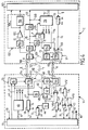
- the transmitter 53 includes, as best seen in FIG. 4, a oscillator 55 to generate an ultra high carrier wave frequency, for example at 2.4 GHz, said oscillator being powered by line 52.
- the oscillator 55 is connected to a phase modulator 56 or an amplitude modulator of the 50% and 100% modulation type depending on whether the value of the transmitted bit is 0 or 1, the output of which is linked to the above-mentioned antenna 54.
- the signal emitted E for example with an amplitude of the order of 2V efficient, is received by an antenna 100 of the identification device I with an attenuation of the order of -40 dBm, which represents a attenuation coefficient of 100 times, i.e. the signal received by the identification device has an amplitude of the order of 20 mV.
- the antenna 100 is connected to a radio frequency filter 101 (only shown in Figure 4) to eliminate frequencies parasites.
- the output of the filter 101 is connected to a branch, of a hand, to a low-speed, low-consumption receiver 102 and, on the other hand, to a logarithmic amplifier 103 which allows output an effective signal of the order of 2V, and serves as high frequency receiver.
- Low speed sk signals are not transmitted by the amplifier 103, but pass essentially via the receiver 102.
- the receiver 102 successively includes a radio frequency envelope detector 104 to reconstruct the low cadence signals on line I5, which correspond to those of line V5.
- Detector output envelope 104 is connected to a low frequency amplifier 105, of which the output is connected in parallel, on the one hand, to a sequence decoder awakening 106 and, on the other hand, to a microcontroller 107 of the device identification I via line 108.
- the decoder 106 is permanently supplied by the battery of the identification device.
- the awakening data e are decoded by the decoder 106, in order to send an awakening command to the micro-controller 107, at the output of the decoder 106.
- the micro-controller 107 then awakens all the other electronic components of the device identification.
- the following data namely the signals R, f and s, are transmitted directly to the microcontroller 107 via the line in parallel 108.
- the microcontroller 50 of vehicle V After transmission of the service data s, the microcontroller 50 of vehicle V generates anti-piracy bits h at the slow rate sk of the microprocessor, said anti-piracy bits being received by a 58 random binary sequence generator buffer output the high-speed anti-piracy bits fk, on a line V7.
- the output of buffer memory 58 is connected to a branch, on the one hand, with the phase modulator or amplitude 56 to phase-modulate the carrier wave generated by oscillator 55, and on the other hand, with a digital self-timer useful bit time 59, the function of which will be explained later. Every bit anti-piracy is transmitted as a radio frequency signal via antenna 54 towards the identification device I.
- each anti-piracy bit is carried by a very high oscillating wave frequency having a bit time Ta for example of the order of 200 ns.
- the emission of the anti-piracy bits h1, h2 ... hn is authorized or prohibited, as a function of a control signal V1 which is emitted by a vehicle V time base management unit 60, which unit 60 is capable of delivering clock signals at low cadence sk, at medium cadence mk and high cadence fk.
- the unit 60 is connected to the microcontroller 50, as indicated by the double arrow 61.
- the signal V1 is generated at the predetermined high rate fk and controls alternatively, on the one hand, stopping and starting the oscillator 55 and, on the other hand, a receiver 62 of the central unit.
- the identification device I receives via its antenna 100 on the line I1 (see figure 6) a signal which corresponds to the anti-piracy bit h1 emitted by vehicle V, with a delay time ⁇ which corresponds to signal propagation time between vehicle and device identification.
- the signal then passes through the amplifier 103, the output is connected to a branch between, on the one hand, a unit of measurement of average bit length 124 and, on the other hand, a timer digital 125 to delay the signal by a useful bit time Tb, at the frequency fk.
- FIG. 8 shows the signal I2 which corresponds to the digital signal at the output of the self-timer 125, said signal being delayed by a useful bit time Tb, Tb possibly being equal or different from Ta.
- the output of the self-timer 125 is connected to an input an exclusive OR logic gate 109, the other input of which receives a encrypted authentication control signal g, the frame of which is shown on line I6.
- the bit rate of the signals g is at medium rate mk, lower than the high rate fk of the anti-piracy bits h.
- the microcontroller 107 of the device identification transmits signal g at low speed sk to a memory buffer 110 which outputs the signal g at the average rate mk to mixer 109.
- the mixer 109 outputs a digital signal of control shown in 17.
- the output of the mixer 109 is connected to a transmitter 111 for transmitting a response signal R via an antenna 112, at an amplitude of the order of 2V effective, towards the vehicle V, as represented by arrow R.
- the identification device When receiving each signal representative of a bit anti-piracy, the identification device is able to detect the front descending F of the signal at the output of amplifier 103, in a Falling edge detector 113, as visible in FIG. 4. This last one is able to control a scale 114 with a slight delay of safety ⁇ to avoid any overlap between reception and the emission of the signal at the identification device.
- This flip-flop 114 controls the start of a high frequency oscillator 115 of the transmitter 111, after the slight delay ⁇ , which oscillator 115 is connected at output to a phase or amplitude modulator 118 of said transmitter 111, said modulator 118 being controlled by signal 17 in mixer 109 output.
- detector 113 sends a bit synchronization signal via line 119 to a time base management unit 116 which delivers the aforementioned clock signals sk, mk and fk, said unit 116 being connected to the microcontroller 107 via line 117.
- Said unit 116 is suitable for command rocker 114 to switch it to its stop state of oscillator 115, at the end of time bit Tb, as visible on the Figure 4.
- ⁇ near from 0 s.
- the duration of signal transmission is of the order of 3 ns per meter of distance between the vehicle and the identification device I.
- the propagation time ⁇ would be around 30 ns.
- the response time of the electronic circuits which could be of the order of a few ns, or tens of ns, depending on the bandwidth allocated to the carrier.
- the signal re-transmitted by the identification device is received by a receiver 62 via an antenna 63, with an attenuation of the order of - 40 dBm, which represents an attenuation coefficient of 100 times, that is, the signal received by the vehicle has an amplitude of around 20 mV.
- the receiver 62 includes a radio frequency filter 64 connected to the antenna 63, whose output signal is represented by line V3, this signal being delivered to the input of a logarithmic amplifier 65 which has a gain of 80 dB, which achieves a coefficient of multiplication of up to 10,000 times, and in particular to deliver in output of said amplifier 65 a signal of the order of 2V effective.
- Amplifier 65 is controlled by signal V1 and is connected at output to a phase or amplitude demodulator 67.
- the amplifier 65 Since the amplifier 65 is controlled by the signal V1, said amplifier switches to its inactive state when it starts the emission of the second bit of anti-piracy h2, as indicated on the line V1 in figure 6.
- the central unit receives the response signal from the identification device I with a delay equal to 2 ⁇ + ⁇ , only the start of the response signal is processed by the receiver 65 and therefore demodulated by demodulator 67, as indicated on line V9, whose demodulated signal has a duration Tc which is less than the duration Ta of the transmit bit and the duration Tb of the transmit bit reply.
- the duration Tc of the bit analyzed in response by the central unit is of the order of 150 ns, which corresponds to 75% of the initial signal.
- the phase demodulator 67 delivers a signal representative of the hog function on line V9 which is connected to an input of a door exclusive OR logic 70.
- This logic gate 70 receives on its other input a signal V8 representative of the function h, delivered at the output of the digital self-timer 59.
- Logic gate 70 could be replaced by another type of mixer, as shown in Figure 3.
- the signal V8 corresponds to signal V7 with a delay corresponding to Tb offset of digital self-timer 125 of the identification device I.
- the logic gate 70 outputs a signal V10, which is representative of the offset between the V8 and V9 signals, i.e. a signal representative of the encrypted authentication signal g emitted by the identification device I, with a small offset corresponding to the signal propagation time which is equal to 2 ⁇ , as visible on the figure 8.
- the output of logic gate 70 is connected to a branch between, on the one hand, a low-pass filter 71 at the average rate mk which is the cadence corresponding to the signal g and, on the other hand, another exclusive OR logic gate 73.
- the low-pass filter 71 is connected to a buffer 72, which transforms said signal from cadence mk to cadence sk before sending it to the microcontroller 50 which will compare the signal g received from the authentication device with the g signal generated at vehicle level, for authentication of communication, which corresponds to the last step 10 illustrated on the diagram in Figure 1. Note that this comparison between the two functions g are performed by auto-correlation between the signals, the acceptable auto-correlation threshold being for example set at 90%, knowing that a level of autocorrelation of 50% corresponds to the comparison of two random signals.
- the microcontroller 50 delivers the signal g specific to the vehicle to a buffer memory 74 at the rate sk, so that it sends it back to the cadence mk at the other input of the aforementioned logic gate 73.
- a buffer memory 74 at the rate sk, so that it sends it back to the cadence mk at the other input of the aforementioned logic gate 73.
- the logic gate 73 mixes the V10 and V11 signals in order to output only the offsets due at the signal propagation time between vehicle V and the device identification I, as shown on line V12. Leaving the logic gate 73 is connected to the input of an integrator 75, which goes output a signal V13 which will go up by stairs in function of time, for each slot C representative of the propagation time of the signal.
- Line V13 is connected to a branch line between, share, a first comparator 76 receiving on another input a threshold limit value 76a which corresponds to the propagation time maximum acceptable, for example 50 ns x n, n being the number of bits anti-piracy, and, on the other hand, a second comparator 77 receiving on another entry another threshold limit value 77a lower than the value 76a and which corresponds to the propagation time over the distance authorized.
- a threshold limit value 76a which corresponds to the propagation time maximum acceptable, for example 50 ns x n, n being the number of bits anti-piracy
- a second comparator 77 receiving on another entry another threshold limit value 77a lower than the value 76a and which corresponds to the propagation time over the distance authorized.
- an attempt to hack will be sent or not via line 78 by the first comparator 76 to the microcontroller 50.
- the second comparator 77 will send to the microcontroller 50 via line 79, a signal indicating that communication is done outside the authorized distance, without however constituting a hacking attempt.
- the integrator 75 will sum the elementary time offsets until the end of the anti-piracy frame, as indicated by arrow 75a, unless the communication is interrupted beforehand by the first and second comparators 76 and 77 above.
- microcontroller 50 can deliver different signals from output to the other vehicle components via track 80 shown on Figures 3 and 4.
- the invention by shortening the reception of the signal emitted by the vehicle. AT as an example, as soon as the hacker detects with a relay box the emission by the vehicle of an anti-piracy bit, it can re-issue to the other relay box only the start of said signal, in order to cause the device to send the response signal early identification.
- the signal is shortened by a duration which would correspond to the duration of propagation of the signal over the distance between the identification device and the vehicle, for example compared to the maximum distance allowed.
- the detector 113 of the identification device I is able to detect the front descending from the signal received from the vehicle, shortening the signal emitted by the vehicle makes it possible to anticipate the emission by the response signal identification device, thereby removing any unauthorized delay between sending and receiving the signal anti-piracy by the vehicle, which can thus trap the system.
- the measurement of average bit length 124 of the identification device I allows to measure the average length of the bits received by the device identification from the vehicle. For example if the average length thus measured is less than 90% of the length expected from the bit sent by the vehicle, the unit 124 will then send a hacking attempt signal via line 131 to the microcontroller 107 and a stop signal via line 130 to the basic management unit of time 116. In other words, the unit 124 makes it possible to verify the integrity of the bit received by the identification device and thus makes it possible to detect a hacking attempt, even if the hacker shortens the re-transmission of the signal to the identification device. Indeed, if this shortened signal can trap the integrator 75 of the central processing unit vehicle control, however unit 124 will interpret this signal shortened as an erroneous signal and will thus interrupt the communication.
- the intermediate clock rate mk is between 20 and 60 times lower than the rate fk.
- antennas 54 and 63 of the vehicle V could replace the antennas 54 and 63 of the vehicle V by a single antenna 82 shown in broken lines in FIG. 4, which antenna 82 would be connected to a diplexer 81 shown in broken lines in Figure 4, to switch between the reception mode and the transmission mode as appropriate.
- the diplexers 81 and 120 could thus communicate with each other, as indicated by the double arrow T.
- the vehicle V receives from the device identifying a hos signal where s represents service data which come to modulate the signal h by phase inversion, as it was the case for signal g whose length is less than that of signal h.
Landscapes
- Engineering & Computer Science (AREA)
- Computer Networks & Wireless Communication (AREA)
- Physics & Mathematics (AREA)
- General Physics & Mathematics (AREA)
- Lock And Its Accessories (AREA)
- Selective Calling Equipment (AREA)
- Mobile Radio Communication Systems (AREA)
Abstract
Description
- la figure 1 est un schéma synoptique fonctionnel représentant le protocole d'encryptage pour sécuriser la transmission bidirectionnelle de données entre un véhicule et un dispositif d'identification ;
- la figure 2 est un schéma synoptique fonctionnel illustrant un moyen de piratage du système d'encryptage par l'intermédiaire de deux boítiers relais ;
- la figure 3 est un schéma synoptique fonctionnel simplifié d'un système d'accès mains libres conforme à l'invention ;
- la figure 4 est un schéma synoptique fonctionnel plus détaillé correspondant au schéma de la figure 3 ;
- la figure 5 représente plusieurs chronogrammes illustrant les trames complètes d'interrogation émises par le véhicule et reçues en réponse par le véhicule ;
- la figure 6 est une vue partielle et agrandie d'une portion des chronogrammes de la figure 5, indiquée par la flèche VI, correspondant au début de la séquence d'anti-piratage ;
- la figure 7 reprend les deux premiers chronogrammes de la figure 5 ; et
- la figure 8 est une vue partielle et agrandie d'une portion des chronogrammes de la figure 7, indiquée par la flèche VIII, au cours de la séquence d'anti-piratage.
Claims (14)
- Système d'accès dit mains libres pour véhicule automobile (V), comportant un dispositif d'identification (I) destiné à être porté par un utilisateur (U) et apte à établir une communication bidirectionnelle à distance et sans fil avec une unité centrale de commande embarquée sur le véhicule, pour authentifier l'utilisateur et commander des moyens de condamnation/décondamnation des serrures des ouvrants lorsque l'utilisateur a été reconnu authentique, ledit système étant apte à établir ladite communication bidirectionnelle lorsque le dispositif d'identification est situé à une distance inférieure à une distance limite prédéterminée du véhicule, caractérisé par le fait que ladite unité centrale est apte à engendrer, à une cadence d'horloge haute prédéterminée (fk), lors de la communication, un train de bits d'anti-piratage (h), chaque bit (h1, h2, h3) dudit train étant émis vers le dispositif d'identification (I) sous la forme d'un signal d'interrogation radio-fréquence (E) représentatif dudit bit, de façon qu'après réception dudit signal d'interrogation par le dispositif d'identification, ce dernier émet, avec un retard au moins égal à un temps bit utile (Tb), un signal de réponse vers l'unité centrale de commande, cette dernière comportant au moins un mélangeur (70) apte à mélanger, d'une part, le signal de réponse (R) reçu en provenance du dispositif d'identification et, d'autre part, le train de bits d'anti-piratage (h) engendré par l'unité centrale et retardé d'un temps bit utile (Tb), pour délivrer en sortie dudit mélangeur un signal (V12) représentatif des décalages temporels successifs de chaque bit dudit train d'anti-piratage, ce dernier signal étant reçu à l'entrée d'un intégrateur (75) pour faire la somme des temps de réponse liés à chaque créneau (C) de décalage temporel de bit d'anti-piratage, la sortie dudit intégrateur étant reliée à au moins un premier comparateur (76) pour comparer ladite somme de temps de réponse avec une première valeur de seuil prédéterminée (76a), au-delà de laquelle est détectée une tentative de piratage provoquant l'arrêt de ladite communication.
- Système selon la revendication 1, caractérisé par le fait que la somme des temps de réponse effectuée par l'intégrateur (75), est arrêtée lorsque l'unité centrale de commande détecte la réception du dernier bit du train d'anti-piratage (75a).
- Système selon la revendication 1 ou 2, caractérisé par le fait que la sortie de l'intégrateur (75) est reliée à au moins un second comparateur (77) pour comparer ladite somme de temps de réponse avec une autre valeur de seuil prédéterminée (77a) inférieure à ladite première valeur de seuil prédéterminée (76a), au-delà de laquelle est détectée une communication au-delà de ladite distance limite prédéterminée.
- Système selon l'une des revendications 1 à 3, caractérisé par le fait que le dispositif d'identification (I) comporte un retardateur de signal numérique (125) apte à retarder d'un temps bit utile (Tb) le signal d'interrogation reçu en provenance du véhicule (V), un oscillateur (115) générateur d'ondes porteuses en radio fréquence, relié en sortie à un modulateur de phase ou d'amplitude (118), qui est commandé par le signal en sortie dudit retardateur, pour délivrer en sortie dudit modulateur ledit signal de réponse (I4) destiné à être émis vers le véhicule.
- Système selon la revendication 4, caractérisé par le fait que le dispositif d'identification (I) comporte un détecteur de front descendant (113) pour détecter le front descendant (F) du signal d'interrogation reçu en provenance du véhicule (V), ledit détecteur étant apte à faire basculer ledit oscillateur (115) du dispositif d'identification entre un état d'arrêt correspondant au mode réception du dispositif d'identification et un état de fonctionnement correspondant à son mode d'émission.
- Système selon la revendication 4 ou 5, caractérisé par le fait que le train de bits d'anti-piratage (h) est engendré par l'unité centrale après l'émission des données d'authentification cryptées (R, f) vers le dispositif d'identification (I).
- Système selon la revendication 6, caractérisé par le fait que le dispositif d'identification comporte un mélangeur (109) pour mélanger le signal en sortie dudit retardateur (125) avec un signal numérique d'authentification crypté de réponse (g) du dispositif d'identification, à une cadence (mk) plus lente que celle du train de bits d'anti-piratage (h), le signal de sortie (I7) de ce mélangeur étant apte à commander le modulateur (118) précité du dispositif d'identification.
- Système selon la revendication 7, caractérisé par le fait que l'unité centrale du véhicule (V) comporte un démodulateur de phase ou d'amplitude (67) pour démoduler le signal reçu par le véhicule en provenance du dispositif d'identification (I), une porte logique OU exclusif (70) dont les entrées sont reliées respectivement audit démodulateur de phase et à un retardateur de signal numérique (59), ledit retardateur étant apte à retarder d'un temps bit utile (Tb) chaque bit du train d'anti-piratage (h) engendré par l'unité centrale, ladite porte logique (70) étant apte à délivrer en sortie un signal numérique (V10) représentatif du signal crypté de réponse du dispositif d'identification.
- Système selon la revendication 8, caractérisé par le fait que le signal (V10) délivré en sortie de la porte logique OU exclusif (70) précitée est comparé par l'unité centrale à un signal numérique crypté d'authentification engendré par l'unité centrale, afin d'authentifier le dispositif d'identification.
- Système selon la revendication 8 ou 9, caractérisé par le fait que la sortie de ladite porte logique OU exclusif (70) est reliée à une entrée d'une deuxième porte logique OU exclusif (73) dont l'autre entrée reçoit un signal numérique crypté d'authentification (g) engendré par l'unité centrale, afin de délivrer en sortie ledit signal (V12) représentatif des décalages temporels successifs de chaque bit du train d'anti-piratage.
- Système selon l'une des revendications 1 à 10, caractérisé par le fait que l'unité centrale de commande comporte un oscillateur (55) générateur d'ondes porteuses en radio fréquence, relié à un modulateur de phase ou d'amplitude (56), qui est commandé par le train de bits d'anti-piratage (h) engendré par l'unité centrale du véhicule (V).
- Système selon la revendication 11, caractérisé par le fait que l'unité centrale est apte à commander alternativement l'arrêt et le démarrage de l'oscillateur (55) de l'unité centrale suivant ladite haute cadence d'horloge prédéterminée (fk) pour faire basculer l'unité centrale respectivement en mode réception et émission.
- Système selon la revendication 12, caractérisé par le fait que l'unité centrale est apte à commander l'arrêt ou le fonctionnement d'un récepteur (62) à ladite haute cadence d'horloge (hk), de façon que ledit récepteur (62) délivre au mélangeur (70) de l'unité centrale un signal numérique (V9) représentatif de l'interprétation du début du signal de réponse reçu en provenance du véhicule.
- Système selon l'une des revendications 1 à 13, caractérisé par le fait que le dispositif d'identification (I) comporte une unité (124) de mesure de longueur moyenne des bits reçus, pour mesurer, après démodulation du signal d'interrogation (E) reçu en provenance du véhicule (V), la longueur moyenne des bits d'anti-piratage reçus, ladite unité de mesure étant apte à provoquer l'interruption de la communication lorsque ladite longueur moyenne est inférieure à une valeur prédéterminée, par exemple 90 % de la longueur utile Ta du bit émis par le véhicule.
Applications Claiming Priority (2)
| Application Number | Priority Date | Filing Date | Title |
|---|---|---|---|
| FR0005630 | 2000-05-03 | ||
| FR0005630A FR2808551B1 (fr) | 2000-05-03 | 2000-05-03 | Systeme a anti-piratage pour l'acces mains libres d'un vehicule automobile |
Publications (2)
| Publication Number | Publication Date |
|---|---|
| EP1152107A1 true EP1152107A1 (fr) | 2001-11-07 |
| EP1152107B1 EP1152107B1 (fr) | 2004-06-16 |
Family
ID=8849832
Family Applications (1)
| Application Number | Title | Priority Date | Filing Date |
|---|---|---|---|
| EP20010400875 Expired - Lifetime EP1152107B1 (fr) | 2000-05-03 | 2001-04-05 | Systéme a anti-piratage pour l'accès mains libres d'un véhicule automobile |
Country Status (3)
| Country | Link |
|---|---|
| EP (1) | EP1152107B1 (fr) |
| DE (1) | DE60103804T2 (fr) |
| FR (1) | FR2808551B1 (fr) |
Cited By (1)
| Publication number | Priority date | Publication date | Assignee | Title |
|---|---|---|---|---|
| FR2863989A1 (fr) * | 2003-12-22 | 2005-06-24 | Thomas Dominique Leandr Buriez | Procede et dispositif de protection contre le vol pour un vehicule |
Families Citing this family (2)
| Publication number | Priority date | Publication date | Assignee | Title |
|---|---|---|---|---|
| DE10158200A1 (de) * | 2001-11-28 | 2003-06-12 | Kostal Leopold Gmbh & Co Kg | Verfahren zum Durchführen einer schlüssellosen Zugangsberechtigungskontrolle bei einem Kraftfahrzeug |
| DE10158202A1 (de) * | 2001-11-28 | 2003-06-12 | Kostal Leopold Gmbh & Co Kg | Verfahren zum Durchführen einer schlüssellosen Nutzungsberechtigungskontrolle bei einem Kraftfahrzeug |
Citations (4)
| Publication number | Priority date | Publication date | Assignee | Title |
|---|---|---|---|---|
| DE4020445A1 (de) * | 1990-02-03 | 1992-01-02 | Bayerische Motoren Werke Ag | Sicherheitseinrichtung fuer kraftfahrzeuge |
| DE19632025A1 (de) * | 1996-08-08 | 1998-04-02 | Daimler Benz Ag | Authentikationseinrichtung mit elektronischer Authentikationskommunikation |
| EP0983916A1 (fr) * | 1998-09-02 | 2000-03-08 | Marquardt GmbH | Système de verrouillage, notamment pour véhicule à moteur |
| WO2000012848A1 (fr) * | 1998-09-01 | 2000-03-09 | Leopold Kostal Gmbh & Co. Kg | Procede pour effectuer un controle d'autorisation d'acces sans cle, et unite de controle d'autorisation d'acces sans cle |
-
2000
- 2000-05-03 FR FR0005630A patent/FR2808551B1/fr not_active Expired - Fee Related
-
2001
- 2001-04-05 DE DE2001603804 patent/DE60103804T2/de not_active Expired - Fee Related
- 2001-04-05 EP EP20010400875 patent/EP1152107B1/fr not_active Expired - Lifetime
Patent Citations (4)
| Publication number | Priority date | Publication date | Assignee | Title |
|---|---|---|---|---|
| DE4020445A1 (de) * | 1990-02-03 | 1992-01-02 | Bayerische Motoren Werke Ag | Sicherheitseinrichtung fuer kraftfahrzeuge |
| DE19632025A1 (de) * | 1996-08-08 | 1998-04-02 | Daimler Benz Ag | Authentikationseinrichtung mit elektronischer Authentikationskommunikation |
| WO2000012848A1 (fr) * | 1998-09-01 | 2000-03-09 | Leopold Kostal Gmbh & Co. Kg | Procede pour effectuer un controle d'autorisation d'acces sans cle, et unite de controle d'autorisation d'acces sans cle |
| EP0983916A1 (fr) * | 1998-09-02 | 2000-03-08 | Marquardt GmbH | Système de verrouillage, notamment pour véhicule à moteur |
Cited By (1)
| Publication number | Priority date | Publication date | Assignee | Title |
|---|---|---|---|---|
| FR2863989A1 (fr) * | 2003-12-22 | 2005-06-24 | Thomas Dominique Leandr Buriez | Procede et dispositif de protection contre le vol pour un vehicule |
Also Published As
| Publication number | Publication date |
|---|---|
| EP1152107B1 (fr) | 2004-06-16 |
| DE60103804T2 (de) | 2005-07-14 |
| DE60103804D1 (de) | 2004-07-22 |
| FR2808551B1 (fr) | 2002-07-26 |
| FR2808551A1 (fr) | 2001-11-09 |
Similar Documents
| Publication | Publication Date | Title |
|---|---|---|
| EP1152109B1 (fr) | Système pour le démarrage et/ou l'accès mains libres d'un véhicule automobile | |
| EP3306576A1 (fr) | Procede et systeme d'acces securise a un espace determine au moyen d'un objet portable | |
| FR3084495A1 (fr) | Système passif d’entrée sans clé | |
| FR2552957A1 (fr) | Poste emetteur-recepteur pour un systeme de transmission d'informations par evasion de frequences | |
| FR2794603A1 (fr) | Procede de transmission bidirectionnelle de donnees, et systeme pour sa mise en oeuvre | |
| FR2745539A1 (fr) | Procede de commande d'un dispositif antivol et dispositif antivol commande par un tel procede | |
| WO2019155167A1 (fr) | Procédé de détection d'un équipement portable d'utilisateur dans une zone prédéterminée, à l'intérieur ou à l'extérieur d'un véhicule par ultra haute fréquence, dispositif de détection et équipement d'utilisateur associés | |
| EP1152108B1 (fr) | Système d'accès dit mains libres pour véhicule automobile | |
| WO2018154211A1 (fr) | Détection de présence d'une main humaine sur un ouvrant de véhicule | |
| EP1152107B1 (fr) | Systéme a anti-piratage pour l'accès mains libres d'un véhicule automobile | |
| FR2793562A1 (fr) | Systeme securise pour la commande du deverrouillage d'au moins un ouvrant de vehicule automobile | |
| EP3301838B1 (fr) | Procédé et système de determination d'une distance entre un objet portable et une station de base | |
| FR2797727A1 (fr) | Dispositif d'identification d'habilitation et de declenchement/mise en disponibilite d'une action, notamment pour vehicule automobile | |
| WO2009010470A1 (fr) | Procede de detection du brouillage d'un reseau de radiocommunication, produit programme d'ordinateur, moyen de stockage et circuit correspondants | |
| FR2828967A1 (fr) | Procede d'autorisation de deverrouillage et/ou de demarrage d'un vehicule automobile et dispositif associe | |
| EP1348204A1 (fr) | Systeme de detection du passage d'individus ou objets par une entree-sortie a un espace delimite | |
| EP1378865B1 (fr) | Procédé de contrôle d'accès d'un objet portable personnalisé à un espace déterminé, et objet portable pour la mise en oeuvre du procédé | |
| EP1178169B1 (fr) | Procédé anti-piratage de commande à distance pour véhicule automobile et système pour sa mise en oeuvre | |
| EP1061211B1 (fr) | Procédé pour sécuriser une transmission bidirectionnelle de données avec un identifiant et système pour sa mise en oeuvre | |
| FR2651941A1 (fr) | Dispositif de synchronisation a deux modes, notamment pour la recuperation de la phase de l'horloge trame dans un systeme de transmission a l'alternat. | |
| EP1320080A1 (fr) | Système et procédé de détection du passage d'un individu ou d'un objet par une entrée-sortie à un espace délimité | |
| EP0532409A1 (fr) | Système de transmission d'information à spectre étalé bidirectionnel | |
| FR3161828A1 (fr) | Procédé de détection de présence d’un transpondeur NFC | |
| FR2891519A1 (fr) | Systeme d'ajustement d'informations d'etat d'un vehicule entre au moins deux transmetteurs d'identification | |
| EP1041225B1 (fr) | Système pour sécuriser une transmission bidirectionnelle de données entre un identifiant et un identifieur |
Legal Events
| Date | Code | Title | Description |
|---|---|---|---|
| PUAI | Public reference made under article 153(3) epc to a published international application that has entered the european phase |
Free format text: ORIGINAL CODE: 0009012 |
|
| AK | Designated contracting states |
Kind code of ref document: A1 Designated state(s): AT BE CH CY DE DK ES FI FR GB GR IE IT LI LU MC NL PT SE TR Kind code of ref document: A1 Designated state(s): DE FR GB IT SE |
|
| AX | Request for extension of the european patent |
Free format text: AL;LT;LV;MK;RO;SI |
|
| 17P | Request for examination filed |
Effective date: 20011205 |
|
| AKX | Designation fees paid |
Free format text: DE FR GB IT SE |
|
| GRAP | Despatch of communication of intention to grant a patent |
Free format text: ORIGINAL CODE: EPIDOSNIGR1 |
|
| GRAS | Grant fee paid |
Free format text: ORIGINAL CODE: EPIDOSNIGR3 |
|
| GRAA | (expected) grant |
Free format text: ORIGINAL CODE: 0009210 |
|
| AK | Designated contracting states |
Kind code of ref document: B1 Designated state(s): DE FR GB IT SE |
|
| REG | Reference to a national code |
Ref country code: GB Ref legal event code: FG4D Free format text: NOT ENGLISH |
|
| GBT | Gb: translation of ep patent filed (gb section 77(6)(a)/1977) |
Effective date: 20040616 |
|
| REF | Corresponds to: |
Ref document number: 60103804 Country of ref document: DE Date of ref document: 20040722 Kind code of ref document: P |
|
| REG | Reference to a national code |
Ref country code: SE Ref legal event code: TRGR |
|
| PLBE | No opposition filed within time limit |
Free format text: ORIGINAL CODE: 0009261 |
|
| STAA | Information on the status of an ep patent application or granted ep patent |
Free format text: STATUS: NO OPPOSITION FILED WITHIN TIME LIMIT |
|
| 26N | No opposition filed |
Effective date: 20050317 |
|
| PGFP | Annual fee paid to national office [announced via postgrant information from national office to epo] |
Ref country code: DE Payment date: 20090402 Year of fee payment: 9 Ref country code: FR Payment date: 20090417 Year of fee payment: 9 Ref country code: IT Payment date: 20090424 Year of fee payment: 9 Ref country code: SE Payment date: 20090407 Year of fee payment: 9 |
|
| PGFP | Annual fee paid to national office [announced via postgrant information from national office to epo] |
Ref country code: GB Payment date: 20090401 Year of fee payment: 9 |
|
| EUG | Se: european patent has lapsed | ||
| GBPC | Gb: european patent ceased through non-payment of renewal fee |
Effective date: 20100405 |
|
| REG | Reference to a national code |
Ref country code: FR Ref legal event code: ST Effective date: 20101230 |
|
| PG25 | Lapsed in a contracting state [announced via postgrant information from national office to epo] |
Ref country code: DE Free format text: LAPSE BECAUSE OF NON-PAYMENT OF DUE FEES Effective date: 20101103 |
|
| PG25 | Lapsed in a contracting state [announced via postgrant information from national office to epo] |
Ref country code: GB Free format text: LAPSE BECAUSE OF NON-PAYMENT OF DUE FEES Effective date: 20100405 Ref country code: IT Free format text: LAPSE BECAUSE OF NON-PAYMENT OF DUE FEES Effective date: 20100405 |
|
| PG25 | Lapsed in a contracting state [announced via postgrant information from national office to epo] |
Ref country code: FR Free format text: LAPSE BECAUSE OF NON-PAYMENT OF DUE FEES Effective date: 20100430 |
|
| PG25 | Lapsed in a contracting state [announced via postgrant information from national office to epo] |
Ref country code: SE Free format text: LAPSE BECAUSE OF NON-PAYMENT OF DUE FEES Effective date: 20100406 |