EP1150111A1 - Headspace sampling and monitoring devices and methods - Google Patents
Headspace sampling and monitoring devices and methods Download PDFInfo
- Publication number
- EP1150111A1 EP1150111A1 EP01303612A EP01303612A EP1150111A1 EP 1150111 A1 EP1150111 A1 EP 1150111A1 EP 01303612 A EP01303612 A EP 01303612A EP 01303612 A EP01303612 A EP 01303612A EP 1150111 A1 EP1150111 A1 EP 1150111A1
- Authority
- EP
- European Patent Office
- Prior art keywords
- sparger
- sample
- wastewater
- headspace
- sample receptacle
- Prior art date
- Legal status (The legal status is an assumption and is not a legal conclusion. Google has not performed a legal analysis and makes no representation as to the accuracy of the status listed.)
- Withdrawn
Links
- 238000005070 sampling Methods 0.000 title claims abstract description 104
- 238000000034 method Methods 0.000 title claims description 41
- 238000012806 monitoring device Methods 0.000 title 1
- 239000002351 wastewater Substances 0.000 claims abstract description 112
- 239000000463 material Substances 0.000 claims abstract description 106
- 238000004891 communication Methods 0.000 claims abstract description 65
- 239000006185 dispersion Substances 0.000 claims abstract description 27
- 239000011261 inert gas Substances 0.000 claims abstract description 26
- 238000012544 monitoring process Methods 0.000 claims description 38
- 238000004817 gas chromatography Methods 0.000 claims description 7
- 239000007789 gas Substances 0.000 claims description 5
- 229910044991 metal oxide Inorganic materials 0.000 claims description 5
- 150000004706 metal oxides Chemical class 0.000 claims description 5
- 239000004065 semiconductor Substances 0.000 claims description 5
- 239000012530 fluid Substances 0.000 claims description 3
- 238000007405 data analysis Methods 0.000 abstract 3
- 239000012855 volatile organic compound Substances 0.000 description 33
- YXFVVABEGXRONW-UHFFFAOYSA-N Toluene Chemical compound CC1=CC=CC=C1 YXFVVABEGXRONW-UHFFFAOYSA-N 0.000 description 9
- 230000008569 process Effects 0.000 description 8
- 239000013049 sediment Substances 0.000 description 8
- 230000004044 response Effects 0.000 description 7
- OKKJLVBELUTLKV-UHFFFAOYSA-N Methanol Chemical compound OC OKKJLVBELUTLKV-UHFFFAOYSA-N 0.000 description 6
- 238000004519 manufacturing process Methods 0.000 description 6
- 230000003068 static effect Effects 0.000 description 5
- CSCPPACGZOOCGX-UHFFFAOYSA-N Acetone Chemical compound CC(C)=O CSCPPACGZOOCGX-UHFFFAOYSA-N 0.000 description 4
- -1 but not limited to Substances 0.000 description 4
- 230000010267 cellular communication Effects 0.000 description 4
- 229910052751 metal Inorganic materials 0.000 description 4
- 239000002184 metal Substances 0.000 description 4
- TWNQGVIAIRXVLR-UHFFFAOYSA-N oxo(oxoalumanyloxy)alumane Chemical compound O=[Al]O[Al]=O TWNQGVIAIRXVLR-UHFFFAOYSA-N 0.000 description 4
- 239000002594 sorbent Substances 0.000 description 4
- 239000004575 stone Substances 0.000 description 4
- UHOVQNZJYSORNB-UHFFFAOYSA-N Benzene Chemical compound C1=CC=CC=C1 UHOVQNZJYSORNB-UHFFFAOYSA-N 0.000 description 3
- 238000004458 analytical method Methods 0.000 description 3
- 230000008901 benefit Effects 0.000 description 3
- 230000001934 delay Effects 0.000 description 3
- VLKZOEOYAKHREP-UHFFFAOYSA-N n-Hexane Chemical compound CCCCCC VLKZOEOYAKHREP-UHFFFAOYSA-N 0.000 description 3
- 239000004800 polyvinyl chloride Substances 0.000 description 3
- 229910001220 stainless steel Inorganic materials 0.000 description 3
- 239000010935 stainless steel Substances 0.000 description 3
- 239000000126 substance Substances 0.000 description 3
- 239000006227 byproduct Substances 0.000 description 2
- 230000003750 conditioning effect Effects 0.000 description 2
- 230000001276 controlling effect Effects 0.000 description 2
- 238000010586 diagram Methods 0.000 description 2
- 238000000642 dynamic headspace extraction Methods 0.000 description 2
- 229930195733 hydrocarbon Natural products 0.000 description 2
- 150000002430 hydrocarbons Chemical class 0.000 description 2
- 238000012423 maintenance Methods 0.000 description 2
- 239000013618 particulate matter Substances 0.000 description 2
- 229920000915 polyvinyl chloride Polymers 0.000 description 2
- 229920002545 silicone oil Polymers 0.000 description 2
- 239000008096 xylene Substances 0.000 description 2
- 150000003738 xylenes Chemical class 0.000 description 2
- 150000001298 alcohols Chemical class 0.000 description 1
- 150000001338 aliphatic hydrocarbons Chemical class 0.000 description 1
- 239000012491 analyte Substances 0.000 description 1
- 238000011088 calibration curve Methods 0.000 description 1
- NEHMKBQYUWJMIP-NJFSPNSNSA-N chloro(114C)methane Chemical compound [14CH3]Cl NEHMKBQYUWJMIP-NJFSPNSNSA-N 0.000 description 1
- 238000004140 cleaning Methods 0.000 description 1
- 230000008878 coupling Effects 0.000 description 1
- 238000010168 coupling process Methods 0.000 description 1
- 238000005859 coupling reaction Methods 0.000 description 1
- 238000011156 evaluation Methods 0.000 description 1
- 238000001914 filtration Methods 0.000 description 1
- 239000011521 glass Substances 0.000 description 1
- 238000010438 heat treatment Methods 0.000 description 1
- 238000002347 injection Methods 0.000 description 1
- 239000007924 injection Substances 0.000 description 1
- 230000007774 longterm Effects 0.000 description 1
- 239000000203 mixture Substances 0.000 description 1
- 238000004886 process control Methods 0.000 description 1
- 238000012545 processing Methods 0.000 description 1
- 230000001105 regulatory effect Effects 0.000 description 1
- 238000007789 sealing Methods 0.000 description 1
- 238000000638 solvent extraction Methods 0.000 description 1
- 238000013022 venting Methods 0.000 description 1
Images

Classifications
-
- G—PHYSICS
- G01—MEASURING; TESTING
- G01N—INVESTIGATING OR ANALYSING MATERIALS BY DETERMINING THEIR CHEMICAL OR PHYSICAL PROPERTIES
- G01N33/00—Investigating or analysing materials by specific methods not covered by groups G01N1/00 - G01N31/00
- G01N33/0004—Gaseous mixtures, e.g. polluted air
- G01N33/0009—General constructional details of gas analysers, e.g. portable test equipment
- G01N33/0027—General constructional details of gas analysers, e.g. portable test equipment concerning the detector
- G01N33/0036—General constructional details of gas analysers, e.g. portable test equipment concerning the detector specially adapted to detect a particular component
- G01N33/0047—Organic compounds
-
- G—PHYSICS
- G01—MEASURING; TESTING
- G01N—INVESTIGATING OR ANALYSING MATERIALS BY DETERMINING THEIR CHEMICAL OR PHYSICAL PROPERTIES
- G01N1/00—Sampling; Preparing specimens for investigation
- G01N1/02—Devices for withdrawing samples
- G01N1/22—Devices for withdrawing samples in the gaseous state
- G01N1/2226—Sampling from a closed space, e.g. food package, head space
-
- G—PHYSICS
- G01—MEASURING; TESTING
- G01N—INVESTIGATING OR ANALYSING MATERIALS BY DETERMINING THEIR CHEMICAL OR PHYSICAL PROPERTIES
- G01N33/00—Investigating or analysing materials by specific methods not covered by groups G01N1/00 - G01N31/00
- G01N33/18—Water
-
- G—PHYSICS
- G01—MEASURING; TESTING
- G01N—INVESTIGATING OR ANALYSING MATERIALS BY DETERMINING THEIR CHEMICAL OR PHYSICAL PROPERTIES
- G01N1/00—Sampling; Preparing specimens for investigation
- G01N1/02—Devices for withdrawing samples
- G01N1/22—Devices for withdrawing samples in the gaseous state
- G01N1/2226—Sampling from a closed space, e.g. food package, head space
- G01N2001/2229—Headspace sampling, i.e. vapour over liquid
-
- Y—GENERAL TAGGING OF NEW TECHNOLOGICAL DEVELOPMENTS; GENERAL TAGGING OF CROSS-SECTIONAL TECHNOLOGIES SPANNING OVER SEVERAL SECTIONS OF THE IPC; TECHNICAL SUBJECTS COVERED BY FORMER USPC CROSS-REFERENCE ART COLLECTIONS [XRACs] AND DIGESTS
- Y10—TECHNICAL SUBJECTS COVERED BY FORMER USPC
- Y10T—TECHNICAL SUBJECTS COVERED BY FORMER US CLASSIFICATION
- Y10T436/00—Chemistry: analytical and immunological testing
- Y10T436/25—Chemistry: analytical and immunological testing including sample preparation
- Y10T436/25375—Liberation or purification of sample or separation of material from a sample [e.g., filtering, centrifuging, etc.]
-
- Y—GENERAL TAGGING OF NEW TECHNOLOGICAL DEVELOPMENTS; GENERAL TAGGING OF CROSS-SECTIONAL TECHNOLOGIES SPANNING OVER SEVERAL SECTIONS OF THE IPC; TECHNICAL SUBJECTS COVERED BY FORMER USPC CROSS-REFERENCE ART COLLECTIONS [XRACs] AND DIGESTS
- Y10—TECHNICAL SUBJECTS COVERED BY FORMER USPC
- Y10T—TECHNICAL SUBJECTS COVERED BY FORMER US CLASSIFICATION
- Y10T436/00—Chemistry: analytical and immunological testing
- Y10T436/25—Chemistry: analytical and immunological testing including sample preparation
- Y10T436/25875—Gaseous sample or with change of physical state
Definitions
- the invention relates to sampling and monitoring systems.
- the invention relates to headspace sampling and monitoring systems and methods.
- sampling system is typically used to monitor manufacturing processes, in which the sampling system may include analyzing capabilities.
- the sampling system should obtain a representative sample with minimal operations and time. While such sampling systems have been used in industry, these sampling systems may experience analytical problems, some of which may be attributed to sampling system features and mechanics.
- Manufacturing processes may produce by-products, which need monitoring, such as by sampling and analyzing.
- a manufacturing process may produce volatile organic compound (VOCs) by-products and volatile silicone oils at a process discharge, such as, but not limited to, an aqueous discharge.
- VOCs can comprise mixtures of polar and non-polar hydrocarbons.
- VOCs can pose analytical problems for conventional monitoring and sampling systems.
- Polar and non-polar hydrocarbons generally require two different and distinct processes for sampling from an aqueous discharge.
- Non-polar VOCs such as, but not limited to, benzene, toluene, and aliphatic hydrocarbons including hexane, are generally sampled with a purge-and-trap method.
- polar VOCs including but not limited to acetone, methanol, and other alcohols, are typically sampled by sparging or dynamic headspace sampling.
- polar VOCs can be sampled by direct injection gas chromatography (gc).
- sampling and monitoring systems are known in the art. These systems include on-line systems in which sampling and monitoring is conducted in the "normal" course of manufacturing processes. For example, a representative portion of some wastewater may be directed to a sampling and monitoring system for analyzing that often conducted by purge-and-trap gas chromatography (gc) systems and techniques. While an on-line system has several advantages, it is not always possible to access the wastewater in a manufacturing process. Further, the wastewater that is to be sampled and monitored may not be wastewater that is capable of being sampled on-line. For example, the wastewater may be only accessible after processing is complete, in which the wastewater is collected manually for monitoring.
- gc purge-and-trap gas chromatography
- the manual collection of wastewater can present several problems for sampling and monitoring. These problems include relatively high costs for collecting samples needed for the sampling and monitoring. Further, given the manual aspect of the collecting of samples for monitoring, sediment and other particulate matter may be captured in the sample. Sediments and other particulate matter are undesirable in most monitoring systems. Conduits in conventional sampling systems may be configured too narrowly and be constricted so that fouling and blockage by sediments or particulates often occurs and interrupts monitoring. Thus, filtering of influent aqueous discharge is needed. The filters in monitoring systems need to be cleaned and replaced, which is both inefficient and un-economical.
- a headspace sampling system to monitor materials in wastewater comprises a sample receptacle that can contain a wastewater sample; a sparger chamber vapor column; a sample receptacle cover assembly that connects the sparger chamber vapor column to the sample receptacle; a sparger tube; at least one sensing device; and at least one analytic device.
- the sparger tube and the sample receptacle define a headspace.
- the sparger chamber vapor column is in communication with the sample receptacle and is closed by a sparger chamber vapor column cover at a second end that is opposed to the sample receptacle.
- the sparger tube extends into the sample receptacle and the wastewater sample in the sample receptacle.
- the sparger tube is connected to a source of inert gas at a first end opposed to the sample receptacle and comprises a dispersion device at an end opposed to the first end.
- the sensing device is disposed in the headspace sampling system in the headspace.
- the analytic device is in communication with the at least one sensing device. Inert gas can flow through the sparger tube into the wastewater sample to separate materials from the wastewater, the sparged materials entering the headspace of the headspace sampling system.
- the sparged materials are sensed by the sensing device thus providing material signal characteristics, which can be analyzed by the analytic device to determine characteristics of the material from the material signal characteristics and provide information about the characteristics of the material.
- Another aspect of the invention provides a method for monitoring materials in wastewater.
- the method comprising steps of providing a wastewater sample in a receptacle, in which the wastewater sample is to be monitored; providing a sparger chamber vapor column; disposing the receptacle and sparger chamber vapor column in fluid cooperation so as to define a headspace in the receptacle and sparger chamber vapor column; providing a sparger tube extending into the receptacle and the wastewater sample therein, the sparger tube comprising a dispersion device to expel air into the wastewater sample; providing a flow of inert gas to the dispersion device to separate materials from the wastewater sample into the headspace; sensing the separated materials; and analyzing the separated materials to provide information about the characteristics of the material.
- a further aspect of the invention sets forth a headspace sampling system for separating materials from wastewater, for monitoring the materials separated from the wastewater, analyzing the materials, and communicating results of the analyzing.
- the headspace sampling system comprises a sample receptacle that can contain a wastewater sample that is to be monitored; a sparger chamber vapor column; a sample receptacle cover assembly comprising a sample receptacle cover and a mounting ring, the sample receptacle cover assembly connects the sparger chamber vapor column to the sample receptacle, the sparger tube and the sample receptacle defining a headspace, the sparger chamber vapor column being in communication with the sample receptacle at a first sparger chamber vapor column end and being closed by a sparger chamber vapor column cover at a second end opposed to the sample receptacle; a sparger tube that extends into the sample receptacle and the wastewater sample in the sample receptacle, the sparger tube being connected to a source of iner
- the inert gas can flow through the sparger tube into the wastewater sample to separate materials from the wastewater.
- the materials enter the headspace of the headspace sampling system, and can be sensed by the at least one sensing device.
- the at least one sensing device provides material signal characteristics, which can be analyzed by the analytic device to determine characteristics of the material from the material signal characteristics and provide information about the characteristics of the material.
- a headspace sampling and monitoring system 1 can quickly and accurately determine concentrations of analyte materials, such as, but not limited to, volatile organic compounds, including non-polar and polar VOCs (hereinafter collectively referred to as "VOCs"), toluene, xylenes, methyl chloride, and volatile silicone oils, in waste water samples.
- VOCs non-polar and polar VOCs
- toluene toluene
- xylenes xylenes
- methyl chloride methyl chloride
- volatile silicone oils volatile silicone oils
- the headspace sampling and monitoring system 1 (hereinafter “headspace sampling system”) comprises at least a device for sparging samples of static wastewater, in which the term “static” means that the wastewater is not flowing, as compared to flowing wastewater that is often encountered in a manufacturing system or environment.
- the sparging can separate VOCs from the wastewater, so the VOCs can be detected by a sensing system of the headspace sampling system 1.
- the headspace sampling system 1 can further comprise a sensing system and analytic system for analyzing and evaluating sparged wastewater.
- the sensing system which analyzes and evaluates, can also provide sparged analyzed and evaluated information (hereinafter "sparged information") to at least one user.
- Sparged information can be provided by appropriate communication links, as described below.
- the headspace sampling system 1, as embodied by the invention, comprises a sample receptacle 2.
- the sample receptacle 2 can comprise any appropriately formed receptacle that can cooperate with the features of the headspace sampling system 1, as described hereinafter.
- the sample receptacle 2 can comprise a receptacle that is formed from a non-reactive and non-sorbent material, such as but not limited to at least one of glass and polyvinyl chloride (PVC). These materials are merely exemplary of non-reactive and non-sorbent materials within the scope of the invention.
- PVC polyvinyl chloride
- the sample receptacle 2 is closed by a sample receptacle cover assembly that comprises a sample receptacle cover 3 and a mounting ring 11.
- the sample receptacle cover 3 can define a sample receptacle interior 4 within the sample receptacle 2.
- the sample receptacle cover 3 can be connected to the sample receptacle 2 by any appropriate connection, for example, but not limited to, screw threads, bayonet couplings, friction fits, and combinations thereof.
- a wastewater sample 42 is disposed in the sample receptacle 2.
- the wastewater sample 42 can be provided in the sample receptacle 2 by manual collection.
- headspace sampling system 1 is described herein with respect to static collected wastewater samples 42, this description is merely for illustrative purposes.
- the headspace sampling system 1 is adapted for use with other sampling and monitoring systems, such as, but not limited to, automated sample collection systems.
- the headspace sampling system 1 comprises a sparger tube 5 that extends into the interior of the sample receptacle 2 and into the wastewater sample 42 contained therein.
- the sparger tube 5 can be formed of sturdy non-reactive materials, such as, but not limited to, stainless steel.
- An end 7 of the sparger tube 5 comprises a dispersion device 6.
- the dispersion device 6 can comprise a porous member through which gas for sparging and separating (often referred to as "partitioning") the VOCs can readily pass, for example a spherical porous, fused aluminum oxide diffuser.
- Other exemplary materials for the dispersion device 6 comprise, but are not limited to, porous stone, sintered metal, and other such materials.
- the dispersion device 6 comprises a structure that is not readily clogged by at least one of particulate and sediments in the wastewater. Further, dispersion device 6 comprises a device onto which particulate and sediments in the wastewater do not tend to accumulate.
- the headspace sampling system 1 does not require the time consuming and costly endeavor of wastewater sample conditioning that is normally required by conventional sampling and monitoring systems to remove particulates and sediments.
- the other end of the sparger tube 5 is connected to a source of inert gas 8, for example but not limited to, filtered air.
- the sparger tube 5 comprises a passage therein so that a stream 9 of inert gas from the source of inert gas 8 can flow down the sparger tube 5 to the dispersion device 6.
- the inert gas will exit the dispersion device 6, enter the wastewater sample 42, and separate VOCs and other such materials from the wastewater sample 42 into a headspace 41 in the sample receptacle 2.
- the flow and rate of flow stream 9 of inert gas can be controlled by a flow control device, such as, but not limited to, a flow control meter 10 that is in communication with the sparger tube 5.
- a flow meter 10 can control the flow of the stream 9 of inert gas and also provide a flow rate of the inert gas that enhances separating VOCs from the wastewater sample 42.
- the headspace 41 can communicate with a headspace extension 141 that is located in a sparger chamber vapor column 12.
- the sparger chamber vapor column 12 (hereinafter “sparger column”) comprises a generally cylindrical tubular element that is connected to the sample receptacle cover 3 on the sample receptacle 2.
- a mounting ring 11 of the sample receptacle cover assembly can be used to connect the sparger column 12 to the sample receptacle cover 3 and the sample receptacle 2.
- the sample receptacle cover 3 comprises at least one passage therethrough, so separated VOCs from the waste water sample 42 can communicate with and flow into the headspace extension 141 in the sparger column 12.
- the sparger column 12 is closed at an end opposed to its connection to the sample receptacle cover 3.
- a sparger column cover 13 is disposed on the sparger column 12 that can sealingly engage the sparger column 12. Thus, any separated VOCs in the sparger column 12 will not escape to the ambient atmosphere.
- the sparger column cover 13 comprises at least one fitting or port (hereinafter "port") and can comprise a plurality of ports.
- the sparger column cover 13 comprises a sparger tube port 51 through which the sparger tube 5 can extend into the system 1.
- the sparger column cover 13 can further comprise an exhaust port 14 so that pressure in the sparger column 12 can be vented or exhausted.
- the exhaust port 14 may be vented, connected to an exhaust treatment system, or connected to a condensing system, if desired.
- the sparger column cover 13 may also comprise a sensor port 15 for the sensing system.
- the sensor port 15 permits a sensor lead 276 to extend from a sensing device 275.
- the sensing device 275 can comprise, but is not limited to, at least one of a robust metal-oxide semiconductor (MOS) sensor and micro-gas chromatography (micro-gc) unit, to pass therethrough and connected with analytic devices (as discussed hereinafter).
- MOS metal-oxide semiconductor
- micro-gc micro-gas chromatography
- the term “robust” means that long-term performance occurs with little or no upkeep or maintenance and is not prone to failure. The following description of the invention will refer to a MOS sensor, however, this description is merely exemplary, and is not intended to limit the invention in any manner.
- the sensing device 275 is disposed in the sparger column and is connected through sensor port 15 (Fig. 1) to an analytic device 20.
- the lead 276 from the sensing device 275 can be connected by communication links 301 to an appropriate analytic device 20, and if desired a display 21 and printer 23.
- the analytic device 20 can be selected from a variety of available process analyzers.
- a MOS sensor when in communication with the headspace 41 and 141 and connected to the analytic device 20, can provide real-time and near real-time monitoring and analyzing.
- real-time is used with its accepted meaning in the art, and means that any delays from the time the process variable information is monitored, evaluated and analyzed, and then made available to the machine operator is minimal, for example on the order of minutes, and possibly a few seconds, or even longer if the need for the information is defined as such and the data may still be relevant and of value to the interested party, if any delay is present.
- real-time can mean a time required by a headspace sampling system 1 user to obtain data.
- the headspace sampling system 1 can be connected by communication links 301 to provide data to authorized parties or users of the headspace sampling system 1.
- Fig. 2 illustrates a block diagram of the headspace sampling system 1 static headspace sampling and monitoring system 1.
- the sparged information from the analytic device 20 can be transferred directly to a party, for example by communication link 301.
- the sparged information from the analytic device 20 can be transferred directly to a party, for example by communication links 301 that lead to a common data gathering location 305, such as, but not limited to, a web page.
- the communication links 301 include, but are not limited to, at least one of a phone modem, network connection, communication, radio communication and other wireless communication systems, cellular communication, satellite communication, web access communication, Internet access communication, and Intranet access communication, and combinations thereof.
- the use of a web page with the headspace sampling system 1 provides real-time monitoring and analysis data to parties 320 who can readily benefit from the information.
- evaluations occurred randomly, irregularly, and may not normally be transmitted in an expedited manner.
- parties that are actually located at the headspace sampling system 1 can quickly obtain analyzed and evaluated information, which is provided in a form that is valuable and easy to use.
- other parties 320 that may not be located at the headspace sampling system 1 for example but not limited to regulatory agencies, can also obtain monitored data in real-time, so as to avoid undesirable time delays.
- a party 320 may take immediate steps in response to the data.
- feedback from a party can be provided and received via the communication links.
- the headspace sampling system 1 enhances robustness of sampling and monitoring systems, as the maintenance typically associated with such systems for conditioning sediments and cleaning of the dispersion device is reduced.
- the non-reactive and non-sorbent materials discussed above are merely exemplary. Although, PVC and stainless steel are disclosed, other non-reactive and non-sorbent materials are within the scope of the invention.
- a static wastewater sample 42 is collected in the sample receptacle 2, for example by a manual collection process.
- the wastewater sample 42 and the sample receptacle 2 are placed in cooperation with the other features of the headspace sampling system 1.
- the other features of the headspace sampling system 1 including but not limited to the sparger chamber vapor column 12, the sample receptacle cover 3, the mounting ring 11, the sparger chamber cover 13, and the features associated with the headspace sampling system 1 through the sparger chamber cover 13, can be desk or bench mounted.
- These features of the headspace sampling system 1, as embodied by the invention can be attached to a ring stand, wall, or other support (not illustrated) for the desk or bench operation.
- wastewater samples can be easily placed into the headspace sampling system 1.
- air can be passed through the sparger tube 5 and dispersion device 6 and enter the wastewater sample 42.
- the air separates VOCs from the wastewater sample 42, and the VOCs enter the headspace 41 and the head space extension 141.
- the sensing device 275 can then detect VOCs in the headspace.
- VOCs can then be analyzed by the associated analytic device 20 that can determine a VOC type from the VOC signal characteristics. Further, the VOC type determined by the analytic device 20 can be communicated over the communications link 301, if desired.
- the wastewater sample 42 can be removed from the headspace sampling system 1.
- VOC signals from the sensing device for example a MOS sensor, will return to a zero signal, which indicates absence of VOCs.
- a second wastewater sample may be provided to the headspace sampling system 1, for analyzing.
- Table 1 (below) and Figure 3 provide exemplary data obtained from the headspace sampling system 1 during analyzing processes for various analytes.
- Table 1 (below) and Figure 3 provide expedited monitoring and analysis of the wastewater samples.
- the analyzed data from the analytic device 20 can be compared with response or calibration curves (Fig. 3), which may have been created by measuring known concentrations of VOCs. The comparison may provide indications of a nature of chemicals that are present in the wastewater sample.
- the analytic device 20 of the headspace sampling system 1 can be loaded with and calibrated for known VOC concentrations under conditions for future analyses. Thus, the analytic device 20 can provide future monitoring and sampling operations for the headspace sampling system 1.
- the headspace sampling system 1 may additionally comprise an air influent tube 25 to dilute the VOCs that have been separated from the wastewater sample by the headspace sampling system 1.
- the air influent tube 25 can be connected to at least one of the headspace 41 and headspace extension 141, for example by passing through the cover 3 and a wall of the sparger chamber vapor column 12, respectively.
- the air influent tube 25 is illustrated in dashed lines in Fig. 1 in both positions.
- the air influent tube 25 can add air, for example, but not limited to, filtered air to the headspace 41 or the headspace extension 141 if concentrations of separated VOCs exceed sensing limits of the MOS sensor.
- the headspace sampling system 1 may also include a heater system for heating the wastewater in the sample receptacle 2.
- the heater system 26 is illustrated in phantom in Fig. 1 and can comprise any heater device that can apply heat to the wastewater sample 42. The heat can to facilitate the separating of VOCs from the wastewater sample 42 into the headspace of the headspace sampling system 1.
- the headspace sampling system 1 provides sampling of both non-polar and polar VOCs together without separate monitoring setups. Further, the headspace sampling system 1 can be configured for real-time monitoring and can be coupled to continuous or automated process analyzers. Thus, the headspace sampling system 1 can provide real-time data for process control and feedback, without time delays experienced by conventional sampling and monitoring systems.
Landscapes
- Life Sciences & Earth Sciences (AREA)
- Chemical & Material Sciences (AREA)
- Health & Medical Sciences (AREA)
- Engineering & Computer Science (AREA)
- Analytical Chemistry (AREA)
- Physics & Mathematics (AREA)
- Biochemistry (AREA)
- General Health & Medical Sciences (AREA)
- General Physics & Mathematics (AREA)
- Immunology (AREA)
- Pathology (AREA)
- Food Science & Technology (AREA)
- Medicinal Chemistry (AREA)
- Combustion & Propulsion (AREA)
- Biomedical Technology (AREA)
- Molecular Biology (AREA)
- Sampling And Sample Adjustment (AREA)
Abstract
Description
- The invention relates to sampling and monitoring systems. In particular, the invention relates to headspace sampling and monitoring systems and methods.
- A sampling system is typically used to monitor manufacturing processes, in which the sampling system may include analyzing capabilities. The sampling system should obtain a representative sample with minimal operations and time. While such sampling systems have been used in industry, these sampling systems may experience analytical problems, some of which may be attributed to sampling system features and mechanics.
- Manufacturing processes may produce by-products, which need monitoring, such as by sampling and analyzing. A manufacturing process may produce volatile organic compound (VOCs) by-products and volatile silicone oils at a process discharge, such as, but not limited to, an aqueous discharge. Typically, VOCs can comprise mixtures of polar and non-polar hydrocarbons. VOCs can pose analytical problems for conventional monitoring and sampling systems. Polar and non-polar hydrocarbons generally require two different and distinct processes for sampling from an aqueous discharge. Non-polar VOCs, such as, but not limited to, benzene, toluene, and aliphatic hydrocarbons including hexane, are generally sampled with a purge-and-trap method. However, polar VOCs, including but not limited to acetone, methanol, and other alcohols, are typically sampled by sparging or dynamic headspace sampling. Alternatively, polar VOCs can be sampled by direct injection gas chromatography (gc).
- Various sampling and monitoring systems are known in the art. These systems include on-line systems in which sampling and monitoring is conducted in the "normal" course of manufacturing processes. For example, a representative portion of some wastewater may be directed to a sampling and monitoring system for analyzing that often conducted by purge-and-trap gas chromatography (gc) systems and techniques. While an on-line system has several advantages, it is not always possible to access the wastewater in a manufacturing process. Further, the wastewater that is to be sampled and monitored may not be wastewater that is capable of being sampled on-line. For example, the wastewater may be only accessible after processing is complete, in which the wastewater is collected manually for monitoring.
- The manual collection of wastewater can present several problems for sampling and monitoring. These problems include relatively high costs for collecting samples needed for the sampling and monitoring. Further, given the manual aspect of the collecting of samples for monitoring, sediment and other particulate matter may be captured in the sample. Sediments and other particulate matter are undesirable in most monitoring systems. Conduits in conventional sampling systems may be configured too narrowly and be constricted so that fouling and blockage by sediments or particulates often occurs and interrupts monitoring. Thus, filtering of influent aqueous discharge is needed. The filters in monitoring systems need to be cleaned and replaced, which is both inefficient and un-economical.
- Therefore, a need exists for a headspace sampling system that can adequately and accurately monitor and sparge wastewater samples. Further, a need exists for a headspace sampling system that can provide precise and reproducible data. Furthermore, a need exists for a headspace sampling system that avoids problems with particulates and sediments in manually collected wastewater.
- A headspace sampling system to monitor materials in wastewater is provided in an aspect of the invention. The headspace sampling system comprises a sample receptacle that can contain a wastewater sample; a sparger chamber vapor column; a sample receptacle cover assembly that connects the sparger chamber vapor column to the sample receptacle; a sparger tube; at least one sensing device; and at least one analytic device. The sparger tube and the sample receptacle define a headspace. The sparger chamber vapor column is in communication with the sample receptacle and is closed by a sparger chamber vapor column cover at a second end that is opposed to the sample receptacle. The sparger tube extends into the sample receptacle and the wastewater sample in the sample receptacle. The sparger tube is connected to a source of inert gas at a first end opposed to the sample receptacle and comprises a dispersion device at an end opposed to the first end. The sensing device is disposed in the headspace sampling system in the headspace. The analytic device is in communication with the at least one sensing device. Inert gas can flow through the sparger tube into the wastewater sample to separate materials from the wastewater, the sparged materials entering the headspace of the headspace sampling system. The sparged materials are sensed by the sensing device thus providing material signal characteristics, which can be analyzed by the analytic device to determine characteristics of the material from the material signal characteristics and provide information about the characteristics of the material.
- Another aspect of the invention provides a method for monitoring materials in wastewater. The method comprising steps of providing a wastewater sample in a receptacle, in which the wastewater sample is to be monitored; providing a sparger chamber vapor column; disposing the receptacle and sparger chamber vapor column in fluid cooperation so as to define a headspace in the receptacle and sparger chamber vapor column; providing a sparger tube extending into the receptacle and the wastewater sample therein, the sparger tube comprising a dispersion device to expel air into the wastewater sample; providing a flow of inert gas to the dispersion device to separate materials from the wastewater sample into the headspace; sensing the separated materials; and analyzing the separated materials to provide information about the characteristics of the material.
- A further aspect of the invention sets forth a headspace sampling system for separating materials from wastewater, for monitoring the materials separated from the wastewater, analyzing the materials, and communicating results of the analyzing. The headspace sampling system comprises a sample receptacle that can contain a wastewater sample that is to be monitored; a sparger chamber vapor column; a sample receptacle cover assembly comprising a sample receptacle cover and a mounting ring, the sample receptacle cover assembly connects the sparger chamber vapor column to the sample receptacle, the sparger tube and the sample receptacle defining a headspace, the sparger chamber vapor column being in communication with the sample receptacle at a first sparger chamber vapor column end and being closed by a sparger chamber vapor column cover at a second end opposed to the sample receptacle; a sparger tube that extends into the sample receptacle and the wastewater sample in the sample receptacle, the sparger tube being connected to a source of inert gas at a first end opposed to the sample receptacle, sparger tube comprising a dispersion device at an end opposed to the first end; at least one sensing device disposed in the headspace sampling system in the headspace; at least one analytic device in communication with the at least one sensing device; and communications links that can communicate information about the characteristics of the material. The inert gas can flow through the sparger tube into the wastewater sample to separate materials from the wastewater. The materials enter the headspace of the headspace sampling system, and can be sensed by the at least one sensing device. The at least one sensing device provides material signal characteristics, which can be analyzed by the analytic device to determine characteristics of the material from the material signal characteristics and provide information about the characteristics of the material.
- These and other aspects, advantages and salient features of the invention will become apparent from the following detailed description, which, when taken in conjunction with the annexed drawings, where like parts are designated by like reference characters throughout the drawings, disclose embodiments of the invention.
-
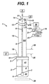
- Figure 1 is a schematic part-sectional illustration of an exemplary headspace sampling and monitoring system, as embodied by the invention;
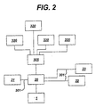
- Figure 2 is a schematic a block diagram of a headspace sampling and monitoring system, as embodied by the invention, connected to analytic and communication devices; and
- Figure 3 is a graph of response curves for various materials measured by an exemplary headspace sampling and monitoring system, as embodied by the invention, illustrating signal versus aqueous concentration.
-
- A headspace sampling and
monitoring system 1, as embodied by the invention, can quickly and accurately determine concentrations of analyte materials, such as, but not limited to, volatile organic compounds, including non-polar and polar VOCs (hereinafter collectively referred to as "VOCs"), toluene, xylenes, methyl chloride, and volatile silicone oils, in waste water samples. The description of the invention will refer to the materials as VOCs in the wastewater, however, this description is merely exemplary of materials to be separated from the wastewater, and is not intended to limit the invention in any manner. - The headspace sampling and monitoring system 1 (hereinafter "headspace sampling system") comprises at least a device for sparging samples of static wastewater, in which the term "static" means that the wastewater is not flowing, as compared to flowing wastewater that is often encountered in a manufacturing system or environment. The sparging can separate VOCs from the wastewater, so the VOCs can be detected by a sensing system of the
headspace sampling system 1. - The
headspace sampling system 1 can further comprise a sensing system and analytic system for analyzing and evaluating sparged wastewater. The sensing system, which analyzes and evaluates, can also provide sparged analyzed and evaluated information (hereinafter "sparged information") to at least one user. The sparged information can be provided by appropriate communication links, as described below. - The
headspace sampling system 1, as embodied by the invention, comprises asample receptacle 2. Thesample receptacle 2 can comprise any appropriately formed receptacle that can cooperate with the features of theheadspace sampling system 1, as described hereinafter. For example, and not intending to limit the invention, thesample receptacle 2 can comprise a receptacle that is formed from a non-reactive and non-sorbent material, such as but not limited to at least one of glass and polyvinyl chloride (PVC). These materials are merely exemplary of non-reactive and non-sorbent materials within the scope of the invention. - The
sample receptacle 2 is closed by a sample receptacle cover assembly that comprises asample receptacle cover 3 and amounting ring 11. Thesample receptacle cover 3 can define asample receptacle interior 4 within thesample receptacle 2. Thesample receptacle cover 3 can be connected to thesample receptacle 2 by any appropriate connection, for example, but not limited to, screw threads, bayonet couplings, friction fits, and combinations thereof. Awastewater sample 42 is disposed in thesample receptacle 2. For example, as discussed above, thewastewater sample 42 can be provided in thesample receptacle 2 by manual collection. Although theheadspace sampling system 1 is described herein with respect to static collectedwastewater samples 42, this description is merely for illustrative purposes. Theheadspace sampling system 1 is adapted for use with other sampling and monitoring systems, such as, but not limited to, automated sample collection systems. - The
headspace sampling system 1 comprises asparger tube 5 that extends into the interior of thesample receptacle 2 and into thewastewater sample 42 contained therein. Thesparger tube 5 can be formed of sturdy non-reactive materials, such as, but not limited to, stainless steel. Anend 7 of thesparger tube 5 comprises adispersion device 6. Thedispersion device 6 can comprise a porous member through which gas for sparging and separating (often referred to as "partitioning") the VOCs can readily pass, for example a spherical porous, fused aluminum oxide diffuser. Other exemplary materials for thedispersion device 6 comprise, but are not limited to, porous stone, sintered metal, and other such materials. Thedispersion device 6 comprises a structure that is not readily clogged by at least one of particulate and sediments in the wastewater. Further,dispersion device 6 comprises a device onto which particulate and sediments in the wastewater do not tend to accumulate. Thus, theheadspace sampling system 1 does not require the time consuming and costly endeavor of wastewater sample conditioning that is normally required by conventional sampling and monitoring systems to remove particulates and sediments. - The other end of the
sparger tube 5 is connected to a source ofinert gas 8, for example but not limited to, filtered air. Thesparger tube 5 comprises a passage therein so that astream 9 of inert gas from the source ofinert gas 8 can flow down thesparger tube 5 to thedispersion device 6. The inert gas will exit thedispersion device 6, enter thewastewater sample 42, and separate VOCs and other such materials from thewastewater sample 42 into aheadspace 41 in thesample receptacle 2. The flow and rate offlow stream 9 of inert gas can be controlled by a flow control device, such as, but not limited to, aflow control meter 10 that is in communication with thesparger tube 5. Thus, aflow meter 10 can control the flow of thestream 9 of inert gas and also provide a flow rate of the inert gas that enhances separating VOCs from thewastewater sample 42. - The
headspace 41 can communicate with aheadspace extension 141 that is located in a spargerchamber vapor column 12. The sparger chamber vapor column 12 (hereinafter "sparger column") comprises a generally cylindrical tubular element that is connected to thesample receptacle cover 3 on thesample receptacle 2. A mountingring 11 of the sample receptacle cover assembly can be used to connect thesparger column 12 to thesample receptacle cover 3 and thesample receptacle 2. Thesample receptacle cover 3 comprises at least one passage therethrough, so separated VOCs from thewaste water sample 42 can communicate with and flow into theheadspace extension 141 in thesparger column 12. - The
sparger column 12 is closed at an end opposed to its connection to thesample receptacle cover 3. A sparger column cover 13 is disposed on thesparger column 12 that can sealingly engage thesparger column 12. Thus, any separated VOCs in thesparger column 12 will not escape to the ambient atmosphere. The sparger column cover 13 comprises at least one fitting or port (hereinafter "port") and can comprise a plurality of ports. The sparger column cover 13 comprises asparger tube port 51 through which thesparger tube 5 can extend into thesystem 1. The sparger column cover 13 can further comprise anexhaust port 14 so that pressure in thesparger column 12 can be vented or exhausted. Theexhaust port 14 may be vented, connected to an exhaust treatment system, or connected to a condensing system, if desired. - The sparger column cover 13 may also comprise a
sensor port 15 for the sensing system. Thesensor port 15 permits asensor lead 276 to extend from asensing device 275. Thesensing device 275 can comprise, but is not limited to, at least one of a robust metal-oxide semiconductor (MOS) sensor and micro-gas chromatography (micro-gc) unit, to pass therethrough and connected with analytic devices (as discussed hereinafter). The term "robust" means that long-term performance occurs with little or no upkeep or maintenance and is not prone to failure. The following description of the invention will refer to a MOS sensor, however, this description is merely exemplary, and is not intended to limit the invention in any manner. Thesensing device 275 is disposed in the sparger column and is connected through sensor port 15 (Fig. 1) to ananalytic device 20. - The lead 276 from the
sensing device 275 can be connected bycommunication links 301 to an appropriateanalytic device 20, and if desired adisplay 21 andprinter 23. Theanalytic device 20 can be selected from a variety of available process analyzers. A MOS sensor when in communication with theheadspace analytic device 20, can provide real-time and near real-time monitoring and analyzing. The term "real-time" is used with its accepted meaning in the art, and means that any delays from the time the process variable information is monitored, evaluated and analyzed, and then made available to the machine operator is minimal, for example on the order of minutes, and possibly a few seconds, or even longer if the need for the information is defined as such and the data may still be relevant and of value to the interested party, if any delay is present. Also, the term "real-time" can mean a time required by aheadspace sampling system 1 user to obtain data. - The
headspace sampling system 1 can be connected bycommunication links 301 to provide data to authorized parties or users of theheadspace sampling system 1. For example, Fig. 2 illustrates a block diagram of theheadspace sampling system 1 static headspace sampling andmonitoring system 1. Further, the sparged information from theanalytic device 20 can be transferred directly to a party, for example bycommunication link 301. Alternatively, the sparged information from theanalytic device 20 can be transferred directly to a party, for example bycommunication links 301 that lead to a commondata gathering location 305, such as, but not limited to, a web page. The communication links 301 include, but are not limited to, at least one of a phone modem, network connection, communication, radio communication and other wireless communication systems, cellular communication, satellite communication, web access communication, Internet access communication, and Intranet access communication, and combinations thereof. - The use of a web page with the
headspace sampling system 1 provides real-time monitoring and analysis data toparties 320 who can readily benefit from the information. In the past, evaluations occurred randomly, irregularly, and may not normally be transmitted in an expedited manner. With theheadspace sampling system 1, as embodied by the invention, parties that are actually located at theheadspace sampling system 1 can quickly obtain analyzed and evaluated information, which is provided in a form that is valuable and easy to use. Also,other parties 320 that may not be located at theheadspace sampling system 1, for example but not limited to regulatory agencies, can also obtain monitored data in real-time, so as to avoid undesirable time delays. With the real-time monitored data, aparty 320 may take immediate steps in response to the data. Also, with the real-time monitored data via communication links, feedback from a party can be provided and received via the communication links. - The
headspace sampling system 1, as embodied by the invention, enhances robustness of sampling and monitoring systems, as the maintenance typically associated with such systems for conditioning sediments and cleaning of the dispersion device is reduced. The non-reactive and non-sorbent materials discussed above are merely exemplary. Although, PVC and stainless steel are disclosed, other non-reactive and non-sorbent materials are within the scope of the invention. - In operation, a
static wastewater sample 42 is collected in thesample receptacle 2, for example by a manual collection process. Thewastewater sample 42 and thesample receptacle 2 are placed in cooperation with the other features of theheadspace sampling system 1. For example, the other features of theheadspace sampling system 1, including but not limited to the spargerchamber vapor column 12, thesample receptacle cover 3, the mountingring 11, thesparger chamber cover 13, and the features associated with theheadspace sampling system 1 through thesparger chamber cover 13, can be desk or bench mounted. These features of theheadspace sampling system 1, as embodied by the invention, can be attached to a ring stand, wall, or other support (not illustrated) for the desk or bench operation. Thus, wastewater samples can be easily placed into theheadspace sampling system 1. - Once the
sample receptacle 2 is connected to the other features of theheadspace sampling system 1, air can be passed through thesparger tube 5 anddispersion device 6 and enter thewastewater sample 42. The air separates VOCs from thewastewater sample 42, and the VOCs enter theheadspace 41 and thehead space extension 141. Thesensing device 275 can then detect VOCs in the headspace. VOCs can then be analyzed by the associatedanalytic device 20 that can determine a VOC type from the VOC signal characteristics. Further, the VOC type determined by theanalytic device 20 can be communicated over the communications link 301, if desired. - Once one
wastewater sample 42 has been analyzed and the analyzing process is complete, thewastewater sample 42 can be removed from theheadspace sampling system 1. VOC signals from the sensing device, for example a MOS sensor, will return to a zero signal, which indicates absence of VOCs. If desired, a second wastewater sample may be provided to theheadspace sampling system 1, for analyzing. - Table 1 (below) and Figure 3 provide exemplary data obtained from the
headspace sampling system 1 during analyzing processes for various analytes. As is evidenced from Table 1, an initial response time is short, thus theheadspace sampling system 1 can provide expedited monitoring and analysis of the wastewater samples. The analyzed data from theanalytic device 20 can be compared with response or calibration curves (Fig. 3), which may have been created by measuring known concentrations of VOCs. The comparison may provide indications of a nature of chemicals that are present in the wastewater sample. Theanalytic device 20 of theheadspace sampling system 1 can be loaded with and calibrated for known VOC concentrations under conditions for future analyses. Thus, theanalytic device 20 can provide future monitoring and sampling operations for theheadspace sampling system 1. The values in Table 1 are approximate, unless specified otherwise.Response of MOS Sensor* in Benchtop Vapor Sampler to Select Chemicals Chemical Conc. (ppb) Max. Signal Time to initial response Time to max. Response Toluene 57 2.7 <5 sec. ∼1 min 114 5.8 <5 sec. ∼1 min 228 13.0 <5 sec. ∼1 min 1142 59.0 <5 sec. ∼1 min Xylenes 114 6.0 <5 sec. ∼1 min 227 10.4 <5 sec. ∼1 min 1136 44.0 <5 sec. ∼1 min D4 505 3.4 <5 sec. ∼1 min 2525 5.1 <5 sec. ∼1 min 25,250 57.8 <5 sec. ∼1 min SF 9600 101,000 0.1 - - MM 202 0.2 <5 sec. ∼1 min 404 2.2 <5 sec. ∼1 min 20,180 42.9 <5 sec. ∼1 min MeOH 4179 0.8 <10 sec. ∼2 min 41,792 8.3 <10 sec. ∼2 min IPA 4150 0.7 <10 sec. ∼2 min 41,475 11.6 <10 sec. ∼2 min Acetone 4180 5.0 <10 sec. ∼2 min 41,800 50.2 <10 sec. ∼2 min Calibration range: 0-100 ppmv - The
headspace sampling system 1 may additionally comprise an airinfluent tube 25 to dilute the VOCs that have been separated from the wastewater sample by theheadspace sampling system 1. The airinfluent tube 25 can be connected to at least one of theheadspace 41 andheadspace extension 141, for example by passing through thecover 3 and a wall of the spargerchamber vapor column 12, respectively. The airinfluent tube 25 is illustrated in dashed lines in Fig. 1 in both positions. The airinfluent tube 25 can add air, for example, but not limited to, filtered air to theheadspace 41 or theheadspace extension 141 if concentrations of separated VOCs exceed sensing limits of the MOS sensor. - Further, the
headspace sampling system 1 may also include a heater system for heating the wastewater in thesample receptacle 2. Theheater system 26 is illustrated in phantom in Fig. 1 and can comprise any heater device that can apply heat to thewastewater sample 42. The heat can to facilitate the separating of VOCs from thewastewater sample 42 into the headspace of theheadspace sampling system 1. - The
headspace sampling system 1 provides sampling of both non-polar and polar VOCs together without separate monitoring setups. Further, theheadspace sampling system 1 can be configured for real-time monitoring and can be coupled to continuous or automated process analyzers. Thus, theheadspace sampling system 1 can provide real-time data for process control and feedback, without time delays experienced by conventional sampling and monitoring systems. - While various embodiments are described herein, it will be appreciated from the specification that various combinations of elements, variations or improvements therein may be made by those skilled in the art, and are within the scope of the invention.
- For completeness, various aspects of the invention are set out in the following numbered clauses:
- 1. A headspace sampling system for monitoring materials in
wastewater, the headspace sampling system comprising:
- a sample receptacle that can contain a wastewater sample that is to be monitored;
- a sparger chamber vapor column;
- a sample receptacle cover assembly comprising a sample receptacle cover and a mounting ring, the sample receptacle cover assembly connects the sparger chamber vapor column to the sample receptacle, the sparger tube and the sample receptacle defining a headspace, the sparger chamber vapor column being in communication with the sample receptacle at a first sparger chamber vapor column end and being closed by a sparger chamber vapor column cover at a second end opposed to the sample receptacle;
- a sparger tube that extends into the sample receptacle and the wastewater sample in the sample receptacle, the sparger tube being connected to a source of inert gas at a first end opposed to the sample receptacle, sparger tube comprising a dispersion device at an end opposed to the first end;
- at least one sensing device disposed in the headspace; and
- at least one analytic device in communication with the at least one sensing device;
- wherein inert gas can flow through the sparger tube into the wastewater sample to separate materials from the wastewater, the sparged materials entering the headspace of the headspace sampling system, the sparged materials being sensed by the at least one sensing device, the at least one sensing device providing material signal characteristics, and the material signal characteristics can be analyzed by the analytic device to determine the material type from the material signal characteristics.
- 2. A system according to
clause 1, the headspace sampling system further comprising communications links that can communicate information about the material. - 3. A system according to
clause 2, wherein the communications links can be connected to a monitor. - 4. A system according to
clause 2, wherein the communications links can be connected to a printer. - 5. A system according to
clause 2, wherein the communications links can be connected to at a network. - 6. A system according to
clause 2, wherein the communications links comprise at least one of: a phone modem, network connection, communication, radio communication and other wireless communication systems, cellular communication, satellite communication, web access communication, Internet access communication, and Intranet access communication, and combinations thereof. - 7. A system according to
clause 1, the headspace sampling system further comprising a heater device, the heater device can apply heat to the wastewater sample in the sample receptacle, the heat can facilitate separating of materials from the wastewater sample into the headspace of the headspace sampling system. - 8. A system according to
clause 1, the headspace sampling system further comprising an air influent tube connected to the headspace to dilute materials that have been separated from the wastewater sample. - 9. A system according to
clause 1, wherein the sparger tube comprises a stainless steel. - 10. A system according to
clause 1, wherein the dispersion comprises a porous member through which gas for sparging can pass. - 11. A system according to
clause 10, wherein the dispersion device comprises at least one of a fused aluminum oxide diffuser, a porous stone diffuser, and a sintered metal diffuser. - 12. A system according to
clause 1, wherein at least one of the sample container, sparger chamber vapor column, and a sample receptacle cover assembly comprise polyvinyl chloride. - 13. A system according to
clause 1, wherein the sparger column cover is disposed on the sparger column to sealingly engage the sparger column to prevent escape of materials. - 14. A system according to
clause 1, wherein the sparger column cover comprises at least one of a sparger tube port through which the sparger tube can extend, and an exhaust port that can vent the headspace. - 15. A system according to
clause 14, wherein the exhaust port may vent the headspace to at least one of an exhaust treatment system and a condensing system. - 16. A system according to
clause 14, wherein the sparger column cover comprises a sensor port for the sensing system. - 17. A system according to
clause 1, wherein the sensor port permits a sensor lead to extend from the at least one a sensing device to the at least one analytic device. - 18. A system according to
clause 16, wherein the at least one sensing device comprises at least one of a metal-oxide semiconductor (MOS) sensor and micro-gas chromatography (micro-gc) sensor unit. - 19. A system according to
clause 1, the headspace sampling system further comprises a flow control meter that can control the flow of the inert gas in the sparger tube, the flow control meter also being able to control a flow rate of the inert gas to the wastewater sample. - 20. A method for separating from wastewater and monitoring the a
material separated from the wastewater, the method comprising:
- providing a wastewater sample in receptacle, in which the wastewater sample is to be monitored;
- providing a sparger chamber vapor column;
- disposing the receptacle and sparger chamber vapor column in fluid cooperation so as to define a headspace in the receptacle and sparger chamber vapor column;
- providing a sparger tube extending into the receptacle and the wastewater sample therein, the sparger tube comprising a dispersion device to expel air into the wastewater sample;
- providing a flow of inert gas to the dispersion device for separating a material from the wastewater sample into the headspace;
- sensing a separated material; and
- analyzing separated materials to provide information about the material.
- 21. A method according to
clause 20, the method further comprising communicating information about the material. - 22. A method according to
clause 21, wherein the step of communicating comprises communicating the information via a monitor. - 23. A method according to
clause 21, wherein the step of communicating comprises communicating the information via a printer. - 24. A method according to
clause 21, wherein the step of communicating comprises communicating the information via a network. - 25. A method according to
clause 21, wherein the step of communicating comprises communicating the information via a communications links selected from at least one of: a phone modem, network connection, communication, radio communication and other wireless communication systems, cellular communication, satellite communication, web access communication, Internet access communication, and Intranet access communication, and combinations thereof. - 26. A method according to
clause 20, the method further comprising a step of applying heat to the wastewater sample to facilitate separating of a material from the wastewater. - 27. A method according to
clause 20, the method further comprising a step of adding air to the headspace to dilute a material. - 28. A method according to
clause 20, the method further comprising a step of selecting the dispersion device from at least one of: a fused aluminum oxide diffuser, a porous stone diffuser, and a sintered metal diffuser. - 29. A method according to
clause 20, the method further comprising a step of sealing the sparger column to prevent escape of a material. - 30. A method according to
clause 20, the method further comprising a step of providing at least one of: a sparger tube port, through which the sparger tube can extend, and an exhaust port that can vent the headspace. - 31. A method according to
clause 30, the method further comprising a step of venting the headspace to at least one of an exhaust treatment system and a condensing system. - 32. A method according to
clause 20, wherein the step of sensing comprises providing a sensing device, the sensing device communicating with the headspace by a sensor port. - 33. A method according to clause 32, wherein the step of analyzing comprises providing an analytic device, wherein the sensor port permits a sensor lead to extend from the sensing device to the analytic device.
- 34. A method according to clause 32, wherein the sensing device comprises at least one of a metal-oxide semiconductor (MOS) sensor and micro-gas chromatography (micro-gc) sensor unit.
- 35. A method according to
clause 20, the method further comprising at least one of a step of controlling a flow of gas and a step of controlling a flow rate of gas. - 36. A headspace sampling system for separating materials from
wastewater, for monitoring the materials separated from the wastewater, analyzing the
materials, and communicating results of the analyzing, the headspace sampling system
comprising:
- a sample receptacle that can contain a wastewater sample that is to be monitored;
- a sparger chamber vapor column;
- a sample receptacle cover assembly comprising a sample receptacle cover and a mounting ring, the sample receptacle cover assembly connects the sparger chamber vapor column to the sample receptacle, the sparger tube and the sample receptacle defining a headspace, the sparger chamber vapor column being in communication with the sample receptacle at a first sparger chamber vapor column end and being closed by a sparger chamber vapor column cover at a second end opposed to the sample receptacle;
- a sparger tube that extends into the sample receptacle and the wastewater sample in the sample receptacle, the sparger tube being connected to a source of inert gas at a first end opposed to the sample receptacle, sparger tube comprising a dispersion device at an end opposed to the first end;
- at least one sensing device disposed in the headspace;
- at least one analytic device in communication with the at least one sensing device; and
- communications links that can communicate information about the characteristics of the material;
- wherein inert gas can flow through the sparger tube into the wastewater sample to separate materials from the wastewater, the sparged materials entering the headspace of the headspace sampling system, the sparged materials being sensed by the at least one sensing device, the at least one sensing device providing material signal characteristics, and the material signal characteristics can be analyzed by the analytic device to determine characteristics of the material from the material signal characteristics and provide information about the characteristics of the material.
- 37. A system according to clause 36, wherein the communications links can be connected to at least one at least one of a monitor, a network, and a printer.
- 38. A system according to clause 36, wherein the communications links comprise at least one of: a phone modem, network connection, communication, radio communication and other wireless communication systems, cellular communication, satellite communication, web access communication, Internet access communication, and Intranet access communication, and combinations thereof.
- 39. A system according to clause 36, the headspace sampling system further comprises a heater device, the heater device can apply heat to the wastewater sample in the sample receptacle, the heat can facilitate separating of materials from the wastewater.
- 40. A system according to clause 36, the headspace sampling system further comprises an air influent tube connected to the headspace to dilute materials that have been separated from the wastewater.
- 41. A system according to clause 36, wherein the dispersion device comprises at least one of a fused aluminum oxide diffuser, a porous stone diffuser, and a sintered metal diffuser.
- 42. A system according to clause 36, wherein the sparger column cover is disposed on the sparger column and sealingly engages the sparger column to prevent escape of materials.
- 43. A system according to clause 36, wherein the sparger column cover comprises a sparger tube port through which the sparger tube can extend, an exhaust port that can vent the headspace, and sensor port for the sensing device.
- 44. A system according to clause 43, wherein the sensor port permits a sensor lead to extend from the at least one a sensing device to the at least one analytic device.
- 45. A system according to clause 36, wherein the sensing device comprises at least one of a metal-oxide semiconductor (MOS) sensor and micro-gas chromatography (micro-gc) sensor unit.
-
Claims (10)
- A headspace sampling system (1) for monitoring materials in wastewater, the headspace sampling system comprising:a sample receptacle (2) that can contain a wastewater sample (4) that is to be monitored;a sparger chamber vapor column (12);a sample receptacle cover assembly comprising a sample receptacle cover (3) and a mounting ring (11), the sample receptacle cover assembly connects the sparger chamber vapor column to the sample receptacle, the sparger tube and the sample receptacle defining a headspace, the sparger chamber vapor column being in communication with the sample receptacle at a first sparger chamber vapor column end and being closed by a sparger chamber vapor column cover at a second end opposed to the sample receptacle;a sparger tube (5) that extends into the sample receptacle and the wastewater sample in the sample receptacle, the sparger tube being connected to a source of inert gas at a first end opposed to the sample receptacle, sparger tube comprising a dispersion device (6) at an end opposed to the first end;at least one sensing device (275) disposed in the headspace; andat least one analytic device (20) in communication with the at least one sensing device;wherein inert gas can flow through the sparger tube into the wastewater sample to separate materials from the wastewater, the sparged materials entering the headspace of the headspace sampling system, the sparged materials being sensed by the at least one sensing device, the at least one sensing device providing material signal characteristics, and the material signal characteristics can be analyzed by the analytic device to determine the material type from the material signal characteristics.
- A headspace sampling system (1) for separating materials from wastewater, for monitoring the materials separated from the wastewater, analyzing the materials, and communicating results of the analyzing, the headspace sampling system comprising:a sample receptacle (2) that can contain a wastewater sample (4) that is to be monitored;a sparger chamber vapor column (12);a sample receptacle cover assembly comprising a sample receptacle cover (3) and a mounting ring (11), the sample receptacle cover assembly connects the sparger chamber vapor column to the sample receptacle, the sparger tube and the sample receptacle defining a headspace, the sparger chamber vapor column being in communication with the sample receptacle at a first sparger chamber vapor column end and being closed by a sparger chamber vapor column cover at a second end opposed to the sample receptacle;a sparger tube (5) that extends into the sample receptacle and the wastewater sample in the sample receptacle, the sparger tube being connected to a source of inert gas at a first end opposed to the sample receptacle, sparger tube comprising a dispersion device (6) at an end opposed to the first end;at least one sensing device (275) disposed in the headspace;at least one analytic device (20) in communication with the at least one sensing device; andcommunications links that can communicate information about the characteristics of the material;wherein inert gas can flow through the sparger tube into the wastewater sample to separate materials from the wastewater, the sparged materials entering the headspace of the headspace sampling system, the sparged materials being sensed by the at least one sensing device, the at least one sensing device providing material signal characteristics, and the material signal characteristics can be analyzed by the analytic device to determine characteristics of the material from the material signal characteristics and provide information about the characteristics of the material.
- A system according to claim 1 or claim 2, the headspace sampling system further comprises a heater device, the heater device can apply heat to the wastewater sample in the sample receptacle, the heat can facilitate separating of materials from the wastewater.
- A system according to any preceding claim, the headspace sampling system further comprises an air influent tube connected to the headspace to dilute materials that have been separated from the wastewater.
- A system according to claim 1, wherein the dispersion device (6) comprises a porous member through which gas for sparging can pass.
- A system according to any preceding claim, wherein the sparger column cover comprises at least one of a sparger tube port (51) through which the sparger tube can extend, and an exhaust port (14) that can vent the headspace.
- A system according to claim 6, wherein the sparger column cover comprises a sensor port for the sensing system.
- A system according to claim 7, wherein the sensor port permits a sensor lead (276) to extend from the at least one sensing device to the at least one analytic device.
- A system according to any preceding claim, wherein the at least one sensing device comprises at least one of a metal-oxide semiconductor (MOS) sensor and micro-gas chromatography (micro-gc) sensor unit.
- A method for separating from wastewater and monitoring the material separated from the wastewater, the method comprising:providing a wastewater sample (4) in receptacle (2), in which the wastewater sample is to be monitored;providing a sparger chamber vapor column (12);disposing the receptacle and sparger chamber vapor column in fluid cooperation so as to define a headspace in the receptacle and sparger chamber vapor column;providing a sparger tube (5) extending into the receptacle and the wastewater sample therein, the sparger tube comprising a dispersion device (6) to expel air into the wastewater sample;providing a flow of inert gas to the dispersion device for separating a material from the wastewater sample into the headspace;sensing a separated material; andanalyzing separated materials to provide information about the material.
Applications Claiming Priority (2)
| Application Number | Priority Date | Filing Date | Title |
|---|---|---|---|
| US556287 | 2000-04-24 | ||
| US09/556,287 US6436710B1 (en) | 2000-04-24 | 2000-04-24 | Headspace sampling and monitoring systems and methods |
Publications (1)
| Publication Number | Publication Date |
|---|---|
| EP1150111A1 true EP1150111A1 (en) | 2001-10-31 |
Family
ID=24220697
Family Applications (1)
| Application Number | Title | Priority Date | Filing Date |
|---|---|---|---|
| EP01303612A Withdrawn EP1150111A1 (en) | 2000-04-24 | 2001-04-20 | Headspace sampling and monitoring devices and methods |
Country Status (3)
| Country | Link |
|---|---|
| US (1) | US6436710B1 (en) |
| EP (1) | EP1150111A1 (en) |
| JP (1) | JP2002005796A (en) |
Cited By (2)
| Publication number | Priority date | Publication date | Assignee | Title |
|---|---|---|---|---|
| WO2007076792A3 (en) * | 2005-12-14 | 2007-12-27 | Univ Kassel | Method and device for the continuous reduction of the odor pollution caused by the waste water in sewers and device for determining the pollution of a water sample with odorous substances |
| CN104583770A (en) * | 2012-09-05 | 2015-04-29 | 株式会社岛津制作所 | Head space sample introduction device and gas chromatograph including same |
Families Citing this family (9)
| Publication number | Priority date | Publication date | Assignee | Title |
|---|---|---|---|---|
| FR2829945B1 (en) * | 2001-09-25 | 2003-10-31 | Geoservices | MODULE FOR EXTRACTING GAS FROM A BASEMENT LIQUID AND INSTALLATION PROVIDED WITH THE MODULE |
| US20040083889A1 (en) * | 2002-11-05 | 2004-05-06 | Rawls Nathan C. | Immersion heater for sparge vessel |
| US20040110299A1 (en) * | 2002-12-10 | 2004-06-10 | Sivavec Timothy Mark | Systems and methods to control humidity effects on sensor performance |
| AU2003213934A1 (en) * | 2003-01-28 | 2004-08-23 | Al Be Farm Research And Development Ltd. | A method and system for treating water |
| US20070184553A1 (en) * | 2006-02-06 | 2007-08-09 | Hartlein Thomas M | Method of automatically regulating and measuring pressure during sampling and analysis of headspace gas |
| US7404311B2 (en) * | 2006-09-11 | 2008-07-29 | Guth Laboratories, Inc. | Breath test simulator |
| KR100880871B1 (en) | 2007-08-28 | 2009-01-30 | 한국해양연구원 | Automatic sampling device and method of sample using headspace |
| ES2369311T3 (en) | 2008-04-18 | 2011-11-29 | Basf Se | TEMPERATE OF A PRODUCT TO BE MEASURED IN A DEPLOYER THROUGH A DIRECT STEAM INJECTION. |
| US9746399B2 (en) | 2012-08-24 | 2017-08-29 | The Unites States of America as represented by the Secretary of Commerce, The National Institute of Standards and Technology | Headspace sampling device and method for sampling |
Citations (3)
| Publication number | Priority date | Publication date | Assignee | Title |
|---|---|---|---|---|
| DE3900799A1 (en) * | 1988-08-05 | 1990-06-07 | Meta Messtechnische Systeme Gm | Measuring apparatus for determining volatile constituents in a liquid by the headspace method |
| DE4007064A1 (en) * | 1990-03-07 | 1991-09-12 | Bayer Ag | DEVICE FOR DETERMINING VOLATILE SUBSTANCES IN A LIQUID |
| JP2000028617A (en) * | 1998-07-14 | 2000-01-28 | Horiba Ltd | Analysis system |
Family Cites Families (7)
| Publication number | Priority date | Publication date | Assignee | Title |
|---|---|---|---|---|
| WO1991013350A2 (en) * | 1990-03-02 | 1991-09-05 | Tekmar Company | Analyzer transport device |
| US5258057A (en) * | 1990-07-02 | 1993-11-02 | Bruker-Franzen Analytik Gmbh | Method and apparatus for extracting dissolved, volatile substances from liquids into the vapor phase |
| US5222032A (en) * | 1990-10-26 | 1993-06-22 | E. I. Du Pont De Nemours And Company | System and method for monitoring the concentration of volatile material dissolved in a liquid |
| US5266496A (en) * | 1992-04-10 | 1993-11-30 | Dacruz Amelia L | Headspace analysis |
| US5363707A (en) * | 1992-05-01 | 1994-11-15 | Hewlett-Packard Company | Headspace sampling system |
| US5792423A (en) * | 1993-06-07 | 1998-08-11 | Markelov; Michael | Headspace autosampler apparatus and method |
| US5693538A (en) * | 1995-08-31 | 1997-12-02 | Olin Corporation | System and method for monitoring volatile species in liquids |
-
2000
- 2000-04-24 US US09/556,287 patent/US6436710B1/en not_active Expired - Fee Related
-
2001
- 2001-04-20 EP EP01303612A patent/EP1150111A1/en not_active Withdrawn
- 2001-04-23 JP JP2001123742A patent/JP2002005796A/en not_active Withdrawn
Patent Citations (3)
| Publication number | Priority date | Publication date | Assignee | Title |
|---|---|---|---|---|
| DE3900799A1 (en) * | 1988-08-05 | 1990-06-07 | Meta Messtechnische Systeme Gm | Measuring apparatus for determining volatile constituents in a liquid by the headspace method |
| DE4007064A1 (en) * | 1990-03-07 | 1991-09-12 | Bayer Ag | DEVICE FOR DETERMINING VOLATILE SUBSTANCES IN A LIQUID |
| JP2000028617A (en) * | 1998-07-14 | 2000-01-28 | Horiba Ltd | Analysis system |
Non-Patent Citations (3)
| Title |
|---|
| CONVERSE J G ET AL: "STATIC HEADSPACE TECHNIQUE APPLIED TO VOLATILE CHEMICALS ANALYSIS IN DIRTY WASTEWATER STREAMS", ADVANCES IN INSTRUMENTATION AND CONTROL, INSTRUMENT SOCIETY OF AMERICA, RESEARCH TRIANGLE PARK, US, vol. 51, no. PART 1, 1996, pages 119 - 130, XP000640488, ISSN: 1054-0032 * |
| PATENT ABSTRACTS OF JAPAN vol. 2000, no. 04 31 August 2000 (2000-08-31) * |
| W. BURGEOIS AND R.M.STUETZ: "Measuring wastewater quality using a sensor array: prospects for real time monitoring", WATER SCIENCE AND TECHNOLOGY, vol. 41, no. 12, 2000, pages 107 - 112, XP002174565 * |
Cited By (3)
| Publication number | Priority date | Publication date | Assignee | Title |
|---|---|---|---|---|
| WO2007076792A3 (en) * | 2005-12-14 | 2007-12-27 | Univ Kassel | Method and device for the continuous reduction of the odor pollution caused by the waste water in sewers and device for determining the pollution of a water sample with odorous substances |
| CN104583770A (en) * | 2012-09-05 | 2015-04-29 | 株式会社岛津制作所 | Head space sample introduction device and gas chromatograph including same |
| CN104583770B (en) * | 2012-09-05 | 2017-06-23 | 株式会社岛津制作所 | Head space sample introduction device and the gas chromatograph for possessing the head space sample introduction device |
Also Published As
| Publication number | Publication date |
|---|---|
| US6436710B1 (en) | 2002-08-20 |
| JP2002005796A (en) | 2002-01-09 |
Similar Documents
| Publication | Publication Date | Title |
|---|---|---|
| US6485688B1 (en) | On-line sparging sampling and monitoring systems and methods | |
| US6436710B1 (en) | Headspace sampling and monitoring systems and methods | |
| US6272938B1 (en) | Monitoring of volatile organic compounds in groundwater with an in-situ sampling device | |
| US6491828B1 (en) | Method and system to remotely monitor groundwater treatment | |
| US6494077B2 (en) | Odor identifying apparatus | |
| CN105353056B (en) | Volatile organic matter on-line monitoring system | |
| US5736654A (en) | Self-contained on-line sampling apparatus | |
| JP3414758B2 (en) | Liquid handler and method for treating liquid | |
| JPH07306127A (en) | Method and equipment for measurement of gas medium using chemical sensor | |
| CN1524063A (en) | Method and system for remote monitoring of carbon adsorption process | |
| JP3282586B2 (en) | Odor measurement device | |
| GB2304891A (en) | Collection and analysis of contaminants in an atmosphere | |
| US5261937A (en) | Sample concentrator filter | |
| CN108061786B (en) | Automatic change water quality testing device of collection, categorised detection and record | |
| US6520033B1 (en) | Apparatus for sampling & analysis of thermally-labile species and a method relating thereto | |
| JP2006337158A (en) | Sample concentrator | |
| KR20240090888A (en) | Gas chromatography instrument for automatically determining the concentration of volatile markers in liquid samples | |
| US20120247188A1 (en) | Gas Sample Collection and Analysis | |
| JPH11226341A (en) | Method and apparatus for clarification of gas | |
| JPH08233797A (en) | Continuous measurement device for carbonyl compounds in the atmosphere | |
| RU2229122C1 (en) | Procedure establishing summary content of hydrocarbons in analyzed mixture | |
| CN117480371A (en) | Systems for separating analytes from samples | |
| JP4089646B2 (en) | Organic volatile matter collection tube and organic volatile matter measurement method | |
| Kostiainen et al. | Purge-and-membrane with ECD. A new screening method for chlorinated aliphatic hydrocarbons | |
| KR200401194Y1 (en) | Device for Pretreating Gas Sample |
Legal Events
| Date | Code | Title | Description |
|---|---|---|---|
| PUAI | Public reference made under article 153(3) epc to a published international application that has entered the european phase |
Free format text: ORIGINAL CODE: 0009012 |
|
| AK | Designated contracting states |
Kind code of ref document: A1 Designated state(s): AT BE CH CY DE DK ES FI FR GB GR IE IT LI LU MC NL PT SE TR Kind code of ref document: A1 Designated state(s): DE FR GB |
|
| AX | Request for extension of the european patent |
Free format text: AL;LT;LV;MK;RO;SI |
|
| 17P | Request for examination filed |
Effective date: 20020502 |
|
| AKX | Designation fees paid |
Free format text: DE FR GB |
|
| STAA | Information on the status of an ep patent application or granted ep patent |
Free format text: STATUS: THE APPLICATION IS DEEMED TO BE WITHDRAWN |
|
| 18D | Application deemed to be withdrawn |
Effective date: 20071101 |