EP1149987B1 - Boítier de turbine - Google Patents
Boítier de turbine Download PDFInfo
- Publication number
- EP1149987B1 EP1149987B1 EP01303799A EP01303799A EP1149987B1 EP 1149987 B1 EP1149987 B1 EP 1149987B1 EP 01303799 A EP01303799 A EP 01303799A EP 01303799 A EP01303799 A EP 01303799A EP 1149987 B1 EP1149987 B1 EP 1149987B1
- Authority
- EP
- European Patent Office
- Prior art keywords
- ring
- strut
- radially
- disposed
- turbine frame
- Prior art date
- Legal status (The legal status is an assumption and is not a legal conclusion. Google has not performed a legal analysis and makes no representation as to the accuracy of the status listed.)
- Expired - Lifetime
Links
Images


Classifications
-
- F—MECHANICAL ENGINEERING; LIGHTING; HEATING; WEAPONS; BLASTING
- F01—MACHINES OR ENGINES IN GENERAL; ENGINE PLANTS IN GENERAL; STEAM ENGINES
- F01D—NON-POSITIVE DISPLACEMENT MACHINES OR ENGINES, e.g. STEAM TURBINES
- F01D25/00—Component parts, details, or accessories, not provided for in, or of interest apart from, other groups
- F01D25/24—Casings; Casing parts, e.g. diaphragms, casing fastenings
-
- F—MECHANICAL ENGINEERING; LIGHTING; HEATING; WEAPONS; BLASTING
- F01—MACHINES OR ENGINES IN GENERAL; ENGINE PLANTS IN GENERAL; STEAM ENGINES
- F01D—NON-POSITIVE DISPLACEMENT MACHINES OR ENGINES, e.g. STEAM TURBINES
- F01D25/00—Component parts, details, or accessories, not provided for in, or of interest apart from, other groups
- F01D25/16—Arrangement of bearings; Supporting or mounting bearings in casings
- F01D25/162—Bearing supports
Landscapes
- Engineering & Computer Science (AREA)
- Mechanical Engineering (AREA)
- General Engineering & Computer Science (AREA)
- Turbine Rotor Nozzle Sealing (AREA)
- Gasket Seals (AREA)
- Connection Of Plates (AREA)
Claims (9)
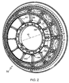
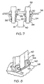
- Cadre de turbine annulaire (32) comprenant :caractérisé en ce que chacun desdits colliers (52) comprend :un premier anneau disposé de manière coaxiale autour d'un axe central axial (12) et comportant une pluralité de premiers orifices circonférentiellement espacés (48) ; etune pluralité de jambes circonférentiellement espacées (40) reliées de façon radiale audit premier anneau par une pluralité correspondante de colliers (52), chaque jambe (40) ayant des première et deuxième extrémités radialement opposées, et un canal traversant (46) qui s'étend entre elles ;chacun desdits colliers (52) étant disposé entre une extrémité respective parmi lesdites premières extrémités de jambe et ledit premier anneau en alignement avec un orifice respectif parmi lesdits premiers orifices (48) pour lier de façon amovible lesdites jambes (40) audit premier anneau ;une base (54) disposée contre ledit premier anneau et comportant une pluralité de trous de montage (56) de collier pour recevoir des boulons d'assemblage (58) dedans afin de lier ladite base (54) de façon amovible audit premier anneau, ladite base (54) comportant une ouverture centrale alignée avec ledit premier orifice (48) ;chaque trou de montage (56) de collier comporte un contre-alésage de trou (80) pratiqué à travers une partie radialement extérieure (82) dudit trou de montage (56) de collier ;une partie radialement intérieure (90) dudit trou de montage (56) de collier est filetée pour recevoir et tenir un insert fileté ;l'insert creux fileté comporte des surfaces filetées intérieure et extérieure ;une rondelle (94) est disposée dans ledit contre-alésage de trou (80) ; etles boulons d'assemblage (58) passent dans des premiers trous d'anneau pratiqués dans ledit premier anneau, dans ladite rondelle (94) puis sont vissés dans ladite surface intérieure filetée dudit insert.
- Cadre de turbine annulaire (32) selon la revendication 1, dans lequel lesdits colliers (52) sont formés d'un seul tenant avec lesdites premières extrémités des jambes.
- Cadre de turbine annulaire (32) selon la revendication 2, comprenant en outre ledit premier anneau ayant des nervures de renforcement annulaires, continues et ininterrompues (72) disposées sur les côtés axiaux opposés desdits colliers (52).
- Cadre de turbine annulaire (32) selon la revendication 1, comprenant en outre un deuxième anneau (38) disposé coaxialement autour dudit axe central avec ledit premier anneau, ledit premier anneau étant un anneau radialement extérieur et ledit deuxième anneau étant un anneau radialement intérieur ;
lesdites premières et deuxièmes extrémités des jambes étant respectivement des extrémités radialement extérieures et intérieures (41, 43) ;
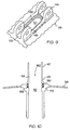
ledit deuxième anneau comportant une pluralité de deuxièmes orifices circonférentiellement espacés (50) s'étendant radialement à travers celui-ci, ladite pluralité de jambes circonférentiellement espacées (40) étant liées auxdits anneaux extérieur et intérieur, ledit canal (46) étant aligné avec un orifice correspondant parmi lesdits premiers et deuxièmes orifices (48, 50) ;
chacun desdits deuxièmes orifices (50) ayant un contre-alésage d'orifice qui traverse une partie radialement extérieure (82) desdits deuxièmes orifices (50) formant un épaulement (156) dans chacun des deuxièmes orifices ; et
un joint (150) placé dans ledit contre-alésage de deuxième orifice, entre ledit épaulement (156) et ladite extrémité intérieure (43) de ladite jambe (40). - Cadre de turbine annulaire (32) selon la revendication 4, dans lequel ledit contre-alésage d'orifice est en forme de champ de courses.
- Cadre de turbine annulaire (32) selon la revendication 4, dans lequel ledit joint (150) est métallique et déformable.
- Cadre de turbine annulaire (32) selon la revendication 6, dans lequel ledit joint (150) est capable de supporter des températures allant jusqu'à 538 °C (1 000 degrés Fahrenheit) et de fonctionner à ces températures.
- Cadre de turbine annulaire (32) selon la revendication 4, dans lequel lesdites jambes circonférentiellement espacées (40) sont reliées radialement par lesdits boulons (58) à des chapes (144) prévues sur ledit anneau intérieur.
- Cadre de turbine annulaire (32) selon la revendication 8, dans lequel ledit anneau extérieur est un carter (36) et ledit anneau intérieur est un moyeu (38).
Applications Claiming Priority (2)
| Application Number | Priority Date | Filing Date | Title |
|---|---|---|---|
| US561771 | 2000-04-29 | ||
| US09/561,771 US6358001B1 (en) | 2000-04-29 | 2000-04-29 | Turbine frame assembly |
Publications (3)
| Publication Number | Publication Date |
|---|---|
| EP1149987A2 EP1149987A2 (fr) | 2001-10-31 |
| EP1149987A3 EP1149987A3 (fr) | 2003-11-19 |
| EP1149987B1 true EP1149987B1 (fr) | 2005-11-09 |
Family
ID=24243390
Family Applications (1)
| Application Number | Title | Priority Date | Filing Date |
|---|---|---|---|
| EP01303799A Expired - Lifetime EP1149987B1 (fr) | 2000-04-29 | 2001-04-26 | Boítier de turbine |
Country Status (4)
| Country | Link |
|---|---|
| US (1) | US6358001B1 (fr) |
| EP (1) | EP1149987B1 (fr) |
| JP (1) | JP4582471B2 (fr) |
| DE (1) | DE60114697T2 (fr) |
Cited By (2)
| Publication number | Priority date | Publication date | Assignee | Title |
|---|---|---|---|---|
| RU2494265C2 (ru) * | 2007-11-09 | 2013-09-27 | Снекма | Устройство соединения радиальных стоек с круглой обечайкой при помощи осей и распорок и газотурбинный двигатель, содержащий такое устройство |
| EP2809919B1 (fr) | 2012-01-30 | 2016-12-14 | United Technologies Corporation | Rayon refroidi de manière interne |
Families Citing this family (70)
| Publication number | Priority date | Publication date | Assignee | Title |
|---|---|---|---|---|
| US6796765B2 (en) * | 2001-12-27 | 2004-09-28 | General Electric Company | Methods and apparatus for assembling gas turbine engine struts |
| DE10213402A1 (de) * | 2002-03-26 | 2003-12-24 | Mtu Aero Engines Gmbh | Anordnung zur Befestigung von als Lagerträger für den Rotor einer Fluggasturbine dienenden Streben an der Gehäusestruktur der Fluggasturbine |
| US6773228B2 (en) * | 2002-07-03 | 2004-08-10 | General Electric Company | Methods and apparatus for turbine nozzle locks |
| US6935837B2 (en) * | 2003-02-27 | 2005-08-30 | General Electric Company | Methods and apparatus for assembling gas turbine engines |
| US6860716B2 (en) * | 2003-05-29 | 2005-03-01 | General Electric Company | Turbomachine frame structure |
| EP1619354B1 (fr) * | 2004-07-22 | 2008-04-09 | Siemens Aktiengesellschaft | Dispositif pour fixer une aube à un disque rotorique de turbomachine, turbomachine et procédé pour le montage et démontage d'une aube au disque rotorique d'une turbomachine |
| US7124572B2 (en) * | 2004-09-14 | 2006-10-24 | Honeywell International, Inc. | Recuperator and turbine support adapter for recuperated gas turbine engines |
| FR2875855B1 (fr) * | 2004-09-27 | 2006-12-22 | Snecma Moteurs Sa | Turboreacteur avec un bras monobloc de raccord de servitudes et le bras monobloc de raccord de servitudes |
| US7383686B2 (en) * | 2004-12-13 | 2008-06-10 | Honeywell International Inc. | Secondary flow, high pressure turbine module cooling air system for recuperated gas turbine engines |
| GB2448116B (en) * | 2007-04-05 | 2009-05-27 | Rolls Royce Plc | Means for cooling a bearing assembly |
| FR2917458B1 (fr) * | 2007-06-13 | 2009-09-25 | Snecma Sa | Moyeu de carter d'echappement comportant des nervures de repartition de contraintes |
| DE102008019156A1 (de) * | 2008-04-17 | 2009-10-22 | Mtu Aero Engines Gmbh | Strebe für ein Turbinenzwischengehäuse, Turbinenzwischengehäuse und Verfahren zur Herstellung eines Turbinenzwischengehäuses |
| FR2933130B1 (fr) * | 2008-06-25 | 2012-02-24 | Snecma | Carter structural pour turbomachine |
| ES2370307B1 (es) * | 2008-11-04 | 2012-11-27 | Industria De Turbo Propulsores, S.A. | Estructura soporte de rodamiento para turbina. |
| US20100132377A1 (en) * | 2008-11-28 | 2010-06-03 | Pratt & Whitney Canada Corp. | Fabricated itd-strut and vane ring for gas turbine engine |
| US8152451B2 (en) * | 2008-11-29 | 2012-04-10 | General Electric Company | Split fairing for a gas turbine engine |
| US8371812B2 (en) * | 2008-11-29 | 2013-02-12 | General Electric Company | Turbine frame assembly and method for a gas turbine engine |
| US8177488B2 (en) * | 2008-11-29 | 2012-05-15 | General Electric Company | Integrated service tube and impingement baffle for a gas turbine engine |
| US8231142B2 (en) * | 2009-02-17 | 2012-07-31 | Pratt & Whitney Canada Corp. | Fluid conduit coupling with leakage detection |
| US20100275572A1 (en) * | 2009-04-30 | 2010-11-04 | Pratt & Whitney Canada Corp. | Oil line insulation system for mid turbine frame |
| FR2950416B1 (fr) * | 2009-09-23 | 2012-04-20 | Snecma | Dispositif accroche-flammes comprenant un support de bras et un ecran de protection thermique monoblocs |
| US8316523B2 (en) | 2009-10-01 | 2012-11-27 | Pratt & Whitney Canada Corp. | Method for centering engine structures |
| US9097141B2 (en) | 2011-09-15 | 2015-08-04 | Pratt & Whitney Canada Corp. | Axial bolting arrangement for mid turbine frame |
| US9279341B2 (en) | 2011-09-22 | 2016-03-08 | Pratt & Whitney Canada Corp. | Air system architecture for a mid-turbine frame module |
| US9316108B2 (en) * | 2012-03-05 | 2016-04-19 | General Electric Company | Gas turbine frame stiffening rails |
| FR2988777B1 (fr) * | 2012-03-29 | 2014-04-25 | Snecma Propulsion Solide | Integration de pieces d'arriere-corps de moteur aeronautique |
| US9482115B2 (en) * | 2012-08-23 | 2016-11-01 | United Technologies Corporation | Turbine engine support assembly including self anti-rotating bushing |
| EP2719870B1 (fr) * | 2012-10-12 | 2016-12-07 | MTU Aero Engines AG | Supportage de palier en étoile, procédé de fabrication et turbomachine associés |
| US10240532B2 (en) | 2012-12-29 | 2019-03-26 | United Technologies Corporation | Frame junction cooling holes |
| WO2014105577A1 (fr) | 2012-12-29 | 2014-07-03 | United Technologies Corporation | Canalisation de dalot dans des modules de turbine à gaz |
| US9631517B2 (en) | 2012-12-29 | 2017-04-25 | United Technologies Corporation | Multi-piece fairing for monolithic turbine exhaust case |
| WO2014105780A1 (fr) | 2012-12-29 | 2014-07-03 | United Technologies Corporation | Ensemble et support de joint de turbine à gaz à usages multiples |
| US9850774B2 (en) | 2012-12-29 | 2017-12-26 | United Technologies Corporation | Flow diverter element and assembly |
| EP2938857B2 (fr) | 2012-12-29 | 2020-11-25 | United Technologies Corporation | Bouclier thermique pour le refroidissement d'une entretoise |
| WO2014105803A1 (fr) | 2012-12-29 | 2014-07-03 | United Technologies Corporation | Ensemble de joint d'étanchéité de turbine à gaz et support de joint d'étanchéité |
| WO2014137444A2 (fr) | 2012-12-29 | 2014-09-12 | United Technologies Corporation | Joint d'étanchéité à doigt à nappes multiples |
| EP2938845A4 (fr) | 2012-12-29 | 2016-01-13 | United Technologies Corp | Architecture de carter de sortie de turbine |
| WO2014105800A1 (fr) | 2012-12-29 | 2014-07-03 | United Technologies Corporation | Ensemble d'étanchéité de turbine à gaz et support d'étanchéité |
| WO2014105602A1 (fr) | 2012-12-29 | 2014-07-03 | United Technologies Corporation | Bouclier thermique pour carter |
| JP6385955B2 (ja) | 2012-12-29 | 2018-09-05 | ユナイテッド テクノロジーズ コーポレイションUnited Technologies Corporation | タービンフレームアセンブリおよびタービンフレームアセンブリを設計する方法 |
| WO2014105826A1 (fr) | 2012-12-29 | 2014-07-03 | United Technologies Corporation | Disque et ensemble de support d'étanchéité |
| US10329956B2 (en) | 2012-12-29 | 2019-06-25 | United Technologies Corporation | Multi-function boss for a turbine exhaust case |
| US10294819B2 (en) | 2012-12-29 | 2019-05-21 | United Technologies Corporation | Multi-piece heat shield |
| WO2014105512A1 (fr) | 2012-12-29 | 2014-07-03 | United Technologies Corporation | Liaison mécanique destinée à un écran thermique segmenté |
| WO2014105657A1 (fr) | 2012-12-29 | 2014-07-03 | United Technologies Corporation | Monture à pattes pouvant être infléchies |
| WO2014105100A1 (fr) | 2012-12-29 | 2014-07-03 | United Technologies Corporation | Pare-chocs pour joints d'étanchéité dans un carter d'échappement de turbine |
| WO2014105604A1 (fr) | 2012-12-29 | 2014-07-03 | United Technologies Corporation | Découpe oblique permettant de diriger une charge de chaleur par rayonnement |
| US9890663B2 (en) | 2012-12-31 | 2018-02-13 | United Technologies Corporation | Turbine exhaust case multi-piece frame |
| DE112013006315T5 (de) | 2012-12-31 | 2015-09-17 | United Technologies Corporation | Mehrteiliger Rahmen eines Turbinenabgasgehäuses |
| WO2014105716A1 (fr) | 2012-12-31 | 2014-07-03 | United Technologies Corporation | Châssis multipièce de boîtier d'échappement de turbine |
| US10330011B2 (en) * | 2013-03-11 | 2019-06-25 | United Technologies Corporation | Bench aft sub-assembly for turbine exhaust case fairing |
| US9598981B2 (en) * | 2013-11-22 | 2017-03-21 | Siemens Energy, Inc. | Industrial gas turbine exhaust system diffuser inlet lip |
| CN103949686A (zh) * | 2013-12-19 | 2014-07-30 | 重庆赛力盟电机有限责任公司 | 水轮机转轮上冠泄水孔加工工艺 |
| CN106460559B (zh) * | 2014-04-11 | 2018-06-12 | 通用电气公司 | 涡轮中央框架整流罩组件 |
| US20160201512A1 (en) * | 2015-01-09 | 2016-07-14 | United Technologies Corporation | Gas turbine engine mid-turbine frame tie rod arrangement |
| US9995171B2 (en) * | 2015-01-16 | 2018-06-12 | United Technologies Corporation | Cooling passages for a mid-turbine frame |
| FR3034465B1 (fr) * | 2015-04-03 | 2017-05-05 | Snecma | Turbomoteur comportant deux flux de ventilation distincts |
| US10247035B2 (en) | 2015-07-24 | 2019-04-02 | Pratt & Whitney Canada Corp. | Spoke locking architecture |
| US10443449B2 (en) | 2015-07-24 | 2019-10-15 | Pratt & Whitney Canada Corp. | Spoke mounting arrangement |
| WO2017015746A1 (fr) | 2015-07-24 | 2017-02-02 | Pratt & Whitney Canada Corp. | Système et procédé de refroidissement de rayons de cadre de turbine intermédiaire |
| US10378379B2 (en) | 2015-08-27 | 2019-08-13 | General Electric Company | Gas turbine engine cooling air manifolds with spoolies |
| US10273812B2 (en) | 2015-12-18 | 2019-04-30 | Pratt & Whitney Canada Corp. | Turbine rotor coolant supply system |
| US10458339B2 (en) | 2016-01-12 | 2019-10-29 | United Technologies Corporation | Gas turbine engine case flow blocking covers |
| DE102016201863A1 (de) * | 2016-02-08 | 2017-08-24 | MTU Aero Engines AG | Gehäuseelement für ein Turbinenzwischengehäuse |
| GB201612293D0 (en) | 2016-07-15 | 2016-08-31 | Rolls Royce Plc | Assembly for supprting an annulus |
| PL419827A1 (pl) * | 2016-12-16 | 2018-06-18 | General Electric Company | Rozpórki do ram wylotowych systemów turbin |
| US11401835B2 (en) | 2017-06-12 | 2022-08-02 | General Electric Company | Turbine center frame |
| BE1025975B1 (fr) * | 2018-02-02 | 2019-09-03 | Safran Aero Boosters S.A. | Carter structural pour turbomachine axiale |
| US10724390B2 (en) * | 2018-03-16 | 2020-07-28 | General Electric Company | Collar support assembly for airfoils |
| CN112392564A (zh) * | 2020-11-13 | 2021-02-23 | 中国航发沈阳发动机研究所 | 一种外环机匣与辐板的连接结构 |
Family Cites Families (17)
| Publication number | Priority date | Publication date | Assignee | Title |
|---|---|---|---|---|
| US2819871A (en) * | 1954-09-07 | 1958-01-14 | John R Mcveigh | Vane structure |
| US3084849A (en) * | 1960-05-18 | 1963-04-09 | United Aircraft Corp | Inlet and bearing support for axial flow compressors |
| US3371697A (en) * | 1966-04-22 | 1968-03-05 | Newton Insert Co | Threaded elements with locking keys |
| DE3003470C2 (de) * | 1980-01-31 | 1982-02-25 | MTU Motoren- und Turbinen-Union München GmbH, 8000 München | Turbinenleitschaufelaufhängung für Gasturbinenstrahltriebwerke |
| US4987736A (en) * | 1988-12-14 | 1991-01-29 | General Electric Company | Lightweight gas turbine engine frame with free-floating heat shield |
| GB2236809B (en) * | 1989-09-22 | 1994-03-16 | Rolls Royce Plc | Improvements in or relating to gas turbine engines |
| FR2685383B1 (fr) * | 1991-12-18 | 1994-02-11 | Snecma | Bras structural du carter d'une turbomachine. |
| US5232323A (en) * | 1992-09-28 | 1993-08-03 | General Electric Company | Removable threaded fastener with locking plate |
| US5272869A (en) | 1992-12-10 | 1993-12-28 | General Electric Company | Turbine frame |
| US5292227A (en) | 1992-12-10 | 1994-03-08 | General Electric Company | Turbine frame |
| US5273397A (en) | 1993-01-13 | 1993-12-28 | General Electric Company | Turbine casing and radiation shield |
| US5483792A (en) | 1993-05-05 | 1996-01-16 | General Electric Company | Turbine frame stiffening rails |
| US5438756A (en) | 1993-12-17 | 1995-08-08 | General Electric Company | Method for assembling a turbine frame assembly |
| FR2738283B1 (fr) * | 1995-08-30 | 1997-09-26 | Snecma | Agencement de turbomachine comprenant une grille d'aubes et un carter intermediaire |
| US5634767A (en) | 1996-03-29 | 1997-06-03 | General Electric Company | Turbine frame having spindle mounted liner |
| US5630700A (en) * | 1996-04-26 | 1997-05-20 | General Electric Company | Floating vane turbine nozzle |
| US6053680A (en) * | 1998-02-16 | 2000-04-25 | Menke; Manfred | Sleeve nut |
-
2000
- 2000-04-29 US US09/561,771 patent/US6358001B1/en not_active Expired - Lifetime
-
2001
- 2001-04-26 DE DE60114697T patent/DE60114697T2/de not_active Expired - Lifetime
- 2001-04-26 EP EP01303799A patent/EP1149987B1/fr not_active Expired - Lifetime
- 2001-04-27 JP JP2001130539A patent/JP4582471B2/ja not_active Expired - Fee Related
Cited By (2)
| Publication number | Priority date | Publication date | Assignee | Title |
|---|---|---|---|---|
| RU2494265C2 (ru) * | 2007-11-09 | 2013-09-27 | Снекма | Устройство соединения радиальных стоек с круглой обечайкой при помощи осей и распорок и газотурбинный двигатель, содержащий такое устройство |
| EP2809919B1 (fr) | 2012-01-30 | 2016-12-14 | United Technologies Corporation | Rayon refroidi de manière interne |
Also Published As
| Publication number | Publication date |
|---|---|
| EP1149987A3 (fr) | 2003-11-19 |
| DE60114697D1 (de) | 2005-12-15 |
| JP4582471B2 (ja) | 2010-11-17 |
| EP1149987A2 (fr) | 2001-10-31 |
| DE60114697T2 (de) | 2006-07-20 |
| US6358001B1 (en) | 2002-03-19 |
| JP2002047902A (ja) | 2002-02-15 |
Similar Documents
| Publication | Publication Date | Title |
|---|---|---|
| EP1149987B1 (fr) | Boítier de turbine | |
| US6439841B1 (en) | Turbine frame assembly | |
| EP1217169B1 (fr) | Connexion des disques d' un rotor par boulonnage | |
| EP2192271B1 (fr) | Moteur à turbine à gaz | |
| EP0601864B1 (fr) | Cadre pour turbine | |
| US7942635B1 (en) | Twin spool rotor assembly for a small gas turbine engine | |
| US5272869A (en) | Turbine frame | |
| EP2192276B1 (fr) | Turbine à gaz avec structure de support pour palier | |
| EP1775517B1 (fr) | Système à boulons pour attacher une chemise en céramique à une structure en métal | |
| US5483792A (en) | Turbine frame stiffening rails | |
| EP2192275B1 (fr) | Moteur à turbine à gaz | |
| CA2672328A1 (fr) | Bati de mi-turbine a gaz | |
| US8636465B2 (en) | Gas turbine engine thermal expansion joint | |
| EP1484495B1 (fr) | Joint à cardan pour un tuyau à jet | |
| US4840026A (en) | Band clamp apparatus | |
| EP1163429B1 (fr) | Dispositif d'etancheite pour anneau de stator segmente | |
| US20200362707A1 (en) | Turbine section assembly with ceramic matrix composite vane | |
| EP3730738B1 (fr) | Ensemble de turbine pour un moteur à turbine à gaz comprenant une aube composite à matrice céramique | |
| EP1217231B1 (fr) | Assemblage par boulons pour rotors et méthode pour y réduire les gradients thermiques | |
| US10954802B2 (en) | Turbine section assembly with ceramic matrix composite vane | |
| US11193393B2 (en) | Turbine section assembly with ceramic matrix composite vane |
Legal Events
| Date | Code | Title | Description |
|---|---|---|---|
| PUAI | Public reference made under article 153(3) epc to a published international application that has entered the european phase |
Free format text: ORIGINAL CODE: 0009012 |
|
| AK | Designated contracting states |
Kind code of ref document: A2 Designated state(s): AT BE CH CY DE DK ES FI FR GB GR IE IT LI LU MC NL PT SE TR |
|
| AX | Request for extension of the european patent |
Free format text: AL;LT;LV;MK;RO;SI |
|
| PUAL | Search report despatched |
Free format text: ORIGINAL CODE: 0009013 |
|
| AK | Designated contracting states |
Kind code of ref document: A3 Designated state(s): AT BE CH CY DE DK ES FI FR GB GR IE IT LI LU MC NL PT SE TR |
|
| AX | Request for extension of the european patent |
Extension state: AL LT LV MK RO SI |
|
| RIC1 | Information provided on ipc code assigned before grant |
Ipc: 7F 16B 37/12 B Ipc: 7F 16B 39/06 B Ipc: 7F 01D 9/06 A Ipc: 7F 01D 25/24 B Ipc: 7F 16L 23/032 B Ipc: 7F 01D 25/16 B Ipc: 7F 16L 23/00 B |
|
| 17P | Request for examination filed |
Effective date: 20040519 |
|
| AKX | Designation fees paid |
Designated state(s): DE FR GB IT |
|
| 17Q | First examination report despatched |
Effective date: 20040804 |
|
| GRAP | Despatch of communication of intention to grant a patent |
Free format text: ORIGINAL CODE: EPIDOSNIGR1 |
|
| GRAS | Grant fee paid |
Free format text: ORIGINAL CODE: EPIDOSNIGR3 |
|
| GRAA | (expected) grant |
Free format text: ORIGINAL CODE: 0009210 |
|
| AK | Designated contracting states |
Kind code of ref document: B1 Designated state(s): DE FR GB IT |
|
| REG | Reference to a national code |
Ref country code: GB Ref legal event code: FG4D |
|
| REF | Corresponds to: |
Ref document number: 60114697 Country of ref document: DE Date of ref document: 20051215 Kind code of ref document: P |
|
| ET | Fr: translation filed | ||
| PLBE | No opposition filed within time limit |
Free format text: ORIGINAL CODE: 0009261 |
|
| STAA | Information on the status of an ep patent application or granted ep patent |
Free format text: STATUS: NO OPPOSITION FILED WITHIN TIME LIMIT |
|
| 26N | No opposition filed |
Effective date: 20060810 |
|
| PGFP | Annual fee paid to national office [announced via postgrant information from national office to epo] |
Ref country code: FR Payment date: 20070417 Year of fee payment: 7 |
|
| REG | Reference to a national code |
Ref country code: FR Ref legal event code: ST Effective date: 20081231 |
|
| PG25 | Lapsed in a contracting state [announced via postgrant information from national office to epo] |
Ref country code: FR Free format text: LAPSE BECAUSE OF NON-PAYMENT OF DUE FEES Effective date: 20080430 |
|
| PGFP | Annual fee paid to national office [announced via postgrant information from national office to epo] |
Ref country code: GB Payment date: 20160427 Year of fee payment: 16 Ref country code: DE Payment date: 20160427 Year of fee payment: 16 |
|
| PGFP | Annual fee paid to national office [announced via postgrant information from national office to epo] |
Ref country code: IT Payment date: 20160421 Year of fee payment: 16 |
|
| REG | Reference to a national code |
Ref country code: DE Ref legal event code: R119 Ref document number: 60114697 Country of ref document: DE |
|
| GBPC | Gb: european patent ceased through non-payment of renewal fee |
Effective date: 20170426 |
|
| PG25 | Lapsed in a contracting state [announced via postgrant information from national office to epo] |
Ref country code: DE Free format text: LAPSE BECAUSE OF NON-PAYMENT OF DUE FEES Effective date: 20171103 |
|
| PG25 | Lapsed in a contracting state [announced via postgrant information from national office to epo] |
Ref country code: GB Free format text: LAPSE BECAUSE OF NON-PAYMENT OF DUE FEES Effective date: 20170426 |
|
| PG25 | Lapsed in a contracting state [announced via postgrant information from national office to epo] |
Ref country code: IT Free format text: LAPSE BECAUSE OF NON-PAYMENT OF DUE FEES Effective date: 20170426 |