EP1149987B1 - Turbine frame assembly - Google Patents
Turbine frame assembly Download PDFInfo
- Publication number
- EP1149987B1 EP1149987B1 EP01303799A EP01303799A EP1149987B1 EP 1149987 B1 EP1149987 B1 EP 1149987B1 EP 01303799 A EP01303799 A EP 01303799A EP 01303799 A EP01303799 A EP 01303799A EP 1149987 B1 EP1149987 B1 EP 1149987B1
- Authority
- EP
- European Patent Office
- Prior art keywords
- ring
- strut
- radially
- disposed
- turbine frame
- Prior art date
- Legal status (The legal status is an assumption and is not a legal conclusion. Google has not performed a legal analysis and makes no representation as to the accuracy of the status listed.)
- Expired - Lifetime
Links
Images


Classifications
-
- F—MECHANICAL ENGINEERING; LIGHTING; HEATING; WEAPONS; BLASTING
- F01—MACHINES OR ENGINES IN GENERAL; ENGINE PLANTS IN GENERAL; STEAM ENGINES
- F01D—NON-POSITIVE DISPLACEMENT MACHINES OR ENGINES, e.g. STEAM TURBINES
- F01D25/00—Component parts, details, or accessories, not provided for in, or of interest apart from, other groups
- F01D25/24—Casings; Casing parts, e.g. diaphragms, casing fastenings
-
- F—MECHANICAL ENGINEERING; LIGHTING; HEATING; WEAPONS; BLASTING
- F01—MACHINES OR ENGINES IN GENERAL; ENGINE PLANTS IN GENERAL; STEAM ENGINES
- F01D—NON-POSITIVE DISPLACEMENT MACHINES OR ENGINES, e.g. STEAM TURBINES
- F01D25/00—Component parts, details, or accessories, not provided for in, or of interest apart from, other groups
- F01D25/16—Arrangement of bearings; Supporting or mounting bearings in casings
- F01D25/162—Bearing supports
Definitions
- the present invention relates generally to gas turbine engines and, more specifically, to frames therein for supporting bearings and shafts.
- Gas turbine engines include one or more rotor shafts supported by bearings which, in turn, are supported by annular frames.
- Frames include an annular casing spaced radially outwardly from an annular hub, with a plurality of circumferentially spaced apart struts extending therebetween.
- the struts may be integrally formed with the casing and hub in a common casting, for example, or may be suitable bolted thereto. In either configuration, the overall frame must have suitable structural rigidity for supporting the rotor shaft to minimize deflections thereof during operation.
- the struts have a hollow cross section through which pressurized cooling air passes and is routed into a hub.
- the pressurized air provides rotor purge for the high pressure and low pressure turbines through holes in the hub.
- the air also provides cooling for the strut and hub in addition to tubes contained within the struts which service the aft hpt bearing. It is important that the pressurized air within the strut and hub not be lost due to leakage. If leakage occurs, the rotor cavity temperatures will be adversely affected.
- a bolted turbine frame assembly is a GE90 turbine center frame (TCF) which has an outer strut end connected to the outer case by eight bolts at each of the twelve strut ends.
- TCF turbine center frame
- a shear bolt is used at each location which bounds off the hole in the case and strut end.
- each strut is located relative to the case and each hole is machined through the case and strut in a single pass. The struts are then separated from the case and each previously machined through hole is used as a pilot to machine a counter-bore feature for subsequent thread tapping and insert installation. It is desirable to be able to machine the counter-bore from a more accessible side of the strut which results in a more producible, reproducible, and less costly design and manufacture of the turbine frame.
- an annular turbine frame in one embodiment, includes a first ring such as radially outer casing disposed coaxially about an axial centerline axis and having a plurality of circumferentially spaced apart first ports.
- a plurality of circumferentially spaced apart hollow struts are joined radially to the fist ring by a corresponding plurality of collars.
- Each strut has radially opposite first and second ends, and a through channel extending therebetween.
- Each of the collars is disposed between a respective one of the strut first ends and the first ring in alignment with a respective one of the first ports for removably joining the struts to the first ring.
- Each of the collars includes a base disposed against the first ring and has a plurality of mounting holes for receiving mounting bolts therethrough to removably join the base to the first ring.
- the base has a central aperture aligned with the first port.
- Each collar mounting hole has a hole counter-bore though a radially outer portion of the collar mounting hole.
- a radially inner portion of the collar mounting hole is threaded to receive and hold a threaded insert which includes inner and outer threaded surfaces.
- a washer is disposed in the hole counter-bore and the mounting bolts are disposed through first ring holes disposed through the first ring, the washer, and screwed into the inner threaded surface of the insert.
- FIG. 1 Illustrated schematically in FIG. 1 is a portion of an exemplary gas turbine engine 10 having an axial or longitudinal centerline axis 12. Disposed about the centerline axis 12 in serial flow communication are a fan, compressor, and combustor (all not shown), high pressure turbine (HPT) 20 and low pressure turbine (LPT) 22. A first shaft (not shown) joins the compressor to the HPT 20, and a second shaft 26 joins the fan to the LPT. During operation, air enters the fan, a portion of which is compressed in the compressor to flow to the combustor wherein it is mixed with fuel and ignited for generating combustion gases 30 which flow downstream through the HPT 20 and the LPT which extract energy therefrom for rotating the first and second shafts.
- HPT high pressure turbine
- LPT low pressure turbine
- An annular turbine frame 32 illustrated as a turbine center frame in accordance with one embodiment of the present invention, supports a bearing 34 which, in turn, supports one end of the second shaft 26 for allowing rotation thereof.
- Turbine frames are also used to support aft ends of the HPT shaft (not shown).
- the turbine frame 32 is disposed downstream of the HPT 20 and, therefore, must be protected from the combustion gases 30 which flow therethrough.
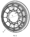
- the turbine frame 32 as illustrated in FIGS. 1 and 2 includes a radially outer first structural ring, illustrated as a casing 36 for example, disposed coaxially about the centerline axis 12.
- the frame 32 also includes a radially inner second structural ring illustrated as a hub 38, for example, disposed coaxially with the first ring or casing 36 about the centerline axis 12 and spaced radially inwardly therefrom.
- a plurality of circumferentially spaced apart hollow struts 40 extend radially between the casing 36 and the hub 38 and are removably fixedly joined thereto.
- the frame 32 also includes a plurality of conventional fairings 42 each of which surrounds a respective one of the struts 40 for protecting the struts from the combustion gases 30 which flow through the turbine frame 32.
- a generally conical sump member 44 which supports the bearing 34 in its central bore is joined to the hub 38.
- Each of the struts 40 includes a first or outer end 41 and a radially opposite second or inner end 43 with an elongate center portion 45 extending therebetween.
- the strut 40 is hollow and includes a through channel 46 extending completely through the strut 40 from the outer end 41 and through the center portion 45 to the inner end 43.
- the casing 36 includes a plurality of circumferentially spaced apart first ports 48 extending radially therethrough and the hub 38 includes a plurality of circumferentially spaced apart second ports 50 extending radially therethrough.
- the inner ends 43 of the struts 40 are removably fixedly joined to the hub 38 with a bolted connection, other embodiments have the inner ends 43 of the struts 40 fixedly attached with welding to or integrally formed with the hub 38 in a common casting.
- the outer ends 41 of the struts 40 are removably fixedly joined to the casing 36.
- the strut outer ends 41 may be integrally joined to the casing 36 in a common casting, for example, with the strut inner ends 43 being removably joined to the hub 38 also in accordance with the present invention.
- a plurality of collars 52 surround and are integrally formed with the strut outer ends 41 and removably join the strut outer ends 41 to the casing 36.
- the collar 52 is illustrated as being integrally formed with the strut outer end 41, the collar can be separate in the form of a clevis as disclosed in U.S. Patent Nos. 5,292,227 and 5,438,756.
- the collar 52 removably joins the strut outer ends 41 to the casing 36.
- collars 52 may be used to removably join the inner ends 43 to the hub 38.
- each of the collars 52 is disposed between a respective one of the strut outer and inner ends 41, 43 and the respective ring, i.e. casing 36 or hub 38, in alignment with respective ones of the first or second ports 48, 50 for removably joining the struts 40 to the first or second ring, i.e. casing 36 or hub 38, for both carrying loads and providing access therethrough.
- each of the collars 52 is an arcuate base 54 disposed against the inner circumference of the casing 36.
- a plurality of casing holes 55 are aligned with a plurality of collar mounting holes 56 in the base 54, eight of each hole being shown for example, for receiving a respective plurality of mounting bolts 58, therethrough to removably fixedly join the base 54 to the casing 36.
- the base 54 includes a central aperture aligned with a respective one of the first ports 48.
- the casing 36 includes a pair of axially spaced apart, annular stiffening ribs 72 disposed on opposite, axial sides of the collars 52 and the first ports 48 for carrying loads between the struts 40 and the casing 36.
- the stiffening ribs 72 are continuous and uninterrupted annular members which carry loads in the hoop-stress direction without interruption by either the ports 48 or the struts 40 joined to the casing 36 so that loads may be transmitted from the hub 38 through the struts 40 and through the collars 52 to the casing 36, with the stiffening ribs 72 ensuring substantially rigid annular members to which the struts 40 are connected.
- each collar mounting hole 56 through the arcuate base 54 of the collar 52 includes a hole counter-bore 80 though a radially outer portion 82 of the mounting hole.
- a threaded hollow insert 84 having inner and outer threaded surfaces, respectively, is used to secure the mounting bolt 58.
- a radially inner portion 90 of the collar mounting hole 56 is threaded to receive and hold the insert 84 disposed therein.
- a washer 94 is disposed in the counter-bore 80 with a press fit.
- the mounting bolts 58 are disposed through the in line-drilled casing holes 55, the washer 94, and mounting holes 56 and screwed into the inner threaded surfaces of the insert 84. This assembly allows an assembler to screw in and tighten the bolts 58 from radially outboard of the casing 36 instead of radially inboard of the casing in a difficult to access area of the frame between the base 54 and the strut outer end 41.
- the mounting bolts 58 seals off the mounting holes 56, thus, preventing leakage of the combustion gases 30 through the casing holes 55 and the casing 36.
- the washer 94 should be made from a material with a higher coefficient of thermal expansion than the strut 40 and base 54 which it is press fit into. The difference in thermal expansion will assure that the washer interference with the hole counter-bore 80 is always present during engine operation.
- One advantage of the present invention is that it enables the hole counter-bore 80 and threads on the inner and outer threaded surfaces to be machined from radially outboard of the casing 36, a more accessible side of the outer strut end 41. This is a more producible and less costly design of the turbine frame.
- the inserts are installed from radially outboard of the casing 36.
- insert keys 120 are radially disposed through aligned radially extending matched key insert hole slots 122 in the insert 84 and hole slots 124 along the inner portion 90 of the casing holes 55 respectively.
- the insert keys 120 are trapped in place by the washer 94 which prevents them from backing out due to engine vibration.
- the washer has tight tolerance diameter and concentricity requirements and this helps the washer take circumferential and axial loads through the struts and transfer them to the annular stiffening ribs 72 on the casing 36.
- the washer will encounter the majority of the assembly/disassembly wear.
- the washer material has a lower hardness than the outer case and will yield/wear before the case if the parts are not aligned during assembly or they are distorted from long term operation. If the washer wears beyond desired limits, it can be easily replaced at a relative low cost as compared to prior art frame assemblies.
- each strut is placed in its assembled position relative to the casing 36 and each pair of the casing holes 55 collar mounting holes 56 is machined through the casing and the strut base 54 in a single pass to assure concentricity between holes in the casing and strut base and that they aligned properly during assembly.
- TCF Turbine Center Frame
- the struts are then separated from the casing and each previously machined through collar mounting hole 56 is used as a pilot to machine the counter-bore 80 though the radially outer portion 82 of the collar hole to a specified depth relative to a reference plane on the strut end for subsequent thread tapping and insert installation.
- the radially inner portion 90 of the collar mounting hole 56 is then enlarged and threaded with a tapping procedure.
- the threaded hollow insert 84 is self broaching and keyed, having at least one key to prevent unwanted rotation.
- the threaded hollow insert 84 is installed flush with the bottom of the counter-bore 80 and the outer threaded surfaces is screwed into the threaded radially inner portion 90 of the collar mounting hole 56.
- the washer 94 is then press fit into the counter-bore 80 and retained by the counter-bore bottom. Once all inserts and washers have been installed, the outer casing is assembled on to the outer strut ends 41. The bolts 58 are then installed through the casing holes 55 and threaded into the inserts 84.
- each of the struts 40 is removably connected to the hub 38 of the frame 32.
- expandable bolts 140 are used to connect the inner end 43 to radially outwardly extending clevises 144 mounted on the casing 36 as shown more particularly in FIG. 9.
- the base 54 has a central aperture 158 aligned with the first port 50 on the hub 38.
- a racetrack shaped hub counter-bore 148 is machined into the base 54 around the second ports 50.
- a seal 150 illustrated in FIG.
- the seal 150 in the exemplary embodiment illustrated herein is metallic and deformable, and is able to withstand and function at temperatures up to and deformable, and is able to withstand and function at temperatures up to 1000 degrees Fahrenheit (538°C).
- the racetrack shaped hub counter-bore148 is machined into the hub 38 at each strut end connection location 170.
- the seal 150 is placed in the hub counter-bore 148 using hand pressure.
- the seal 150 is bowed slightly outward at new part manufacture so that it is retained in the hub counter-bore 148 in the absence of the strut 40. This aids in the assembly of the struts 40 to the hub 38.
- the strut 40 is attached to the hub 38 by first installing a forward one 172 of the expandable bolts 140 then rotating the strut about the forward bolt thus compressing the seal 150 between the strut and hub and then installing an aft one 174 of the expandable bolts. The expandable bolts are then torqued within a specified tolerance.
- the seal 150 is installed, a portion of the seal is visible allowing assembly personal to verify the seal is present.
- the seal is designed to function properly regardless of assembly orientation within the cavity (i.e. the seal can be installed upside down). Due to manufacturing tolerances, the gap between the strut end and hub counter-bore can vary from frame to frame and from strut to strut within a given frame.
- the seal is designed to function properly (meet maximum leakage limits) given the variety of gaps. The seal will also function properly if it is initially installed into a cavity of minimum gap and later installed into a cavity of maximum allowable gap.
Description
- The present invention relates generally to gas turbine engines and, more specifically, to frames therein for supporting bearings and shafts.
- Gas turbine engines include one or more rotor shafts supported by bearings which, in turn, are supported by annular frames. Frames include an annular casing spaced radially outwardly from an annular hub, with a plurality of circumferentially spaced apart struts extending therebetween. The struts may be integrally formed with the casing and hub in a common casting, for example, or may be suitable bolted thereto. In either configuration, the overall frame must have suitable structural rigidity for supporting the rotor shaft to minimize deflections thereof during operation.
- The struts have a hollow cross section through which pressurized cooling air passes and is routed into a hub. The pressurized air provides rotor purge for the high pressure and low pressure turbines through holes in the hub. The air also provides cooling for the strut and hub in addition to tubes contained within the struts which service the aft hpt bearing. It is important that the pressurized air within the strut and hub not be lost due to leakage. If leakage occurs, the rotor cavity temperatures will be adversely affected.
- One example of a bolted turbine frame assembly is a GE90 turbine center frame (TCF) which has an outer strut end connected to the outer case by eight bolts at each of the twelve strut ends. To minimize relative movement between the case and strut end, a shear bolt is used at each location which bounds off the hole in the case and strut end. To assure concentricity between the case hole and strut hole during manufacture, each strut is located relative to the case and each hole is machined through the case and strut in a single pass. The struts are then separated from the case and each previously machined through hole is used as a pilot to machine a counter-bore feature for subsequent thread tapping and insert installation. It is desirable to be able to machine the counter-bore from a more accessible side of the strut which results in a more producible, reproducible, and less costly design and manufacture of the turbine frame.
- In one embodiment of the invention, an annular turbine frame includes a first ring such as radially outer casing disposed coaxially about an axial centerline axis and having a plurality of circumferentially spaced apart first ports. A plurality of circumferentially spaced apart hollow struts are joined radially to the fist ring by a corresponding plurality of collars. Each strut has radially opposite first and second ends, and a through channel extending therebetween. Each of the collars is disposed between a respective one of the strut first ends and the first ring in alignment with a respective one of the first ports for removably joining the struts to the first ring.
- Each of the collars includes a base disposed against the first ring and has a plurality of mounting holes for receiving mounting bolts therethrough to removably join the base to the first ring. The base has a central aperture aligned with the first port. Each collar mounting hole has a hole counter-bore though a radially outer portion of the collar mounting hole. A radially inner portion of the collar mounting hole is threaded to receive and hold a threaded insert which includes inner and outer threaded surfaces. A washer is disposed in the hole counter-bore and the mounting bolts are disposed through first ring holes disposed through the first ring, the washer, and screwed into the inner threaded surface of the insert.
- The invention will now be described in greater detail, by way of example, with reference to the drawings, in which:-
- FIG. 1 is a longitudinal cross-sectional view illustration of a portion of a gas turbine engine having a turbine center frame assembly of an exemplary embodiment of the present invention.
- FIG. 2 is a perspective view illustration of the turbine center frame assembly in FIG. 1.
- FIG. 3 is a perspective view illustration of a strut and casing inside of the turbine center frame assembly in FIG. 2.
- FIG. 4 is a radially outwardly looking perspective view illustration of a radially outer end of the strut in FIG. 3.
- FIG. 5 is a radially inwardly looking perspective view illustration of a radially outer end of the strut in FIG. 3.
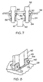
- FIG. 6 is a cross-sectional view illustration of a portion of the casing and strut assembly taken though a bolt and threaded in an insert and a key used to secure the insert in a mounting hole in a strut base illustrated in FIG. 5.
- FIG. 7 is a cross-sectional view illustration of a portion of the casing and strut assembly taken though a bolt and threaded in the insert in the mounting hole in the strut base illustrated in FIG. 5.
- FIG. 8 is a radially inwardly looking perspective view illustration of a radially inner end of the strut and hub in FIG. 2.
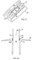
- FIG. 9 is a radially inwardly looking perspective view illustration of the hub in FIG. 8 with the radially inner end of the strut removed.
- FIG. 10 is a diagrammatic cross-sectional perspective view illustration of the hub and the radially inner end of the strut and hub in FIG. 2.
-
- Illustrated schematically in FIG. 1 is a portion of an exemplary
gas turbine engine 10 having an axial orlongitudinal centerline axis 12. Disposed about thecenterline axis 12 in serial flow communication are a fan, compressor, and combustor (all not shown), high pressure turbine (HPT) 20 and low pressure turbine (LPT) 22. A first shaft (not shown) joins the compressor to theHPT 20, and asecond shaft 26 joins the fan to the LPT. During operation, air enters the fan, a portion of which is compressed in the compressor to flow to the combustor wherein it is mixed with fuel and ignited for generatingcombustion gases 30 which flow downstream through theHPT 20 and the LPT which extract energy therefrom for rotating the first and second shafts. - An
annular turbine frame 32, illustrated as a turbine center frame in accordance with one embodiment of the present invention, supports abearing 34 which, in turn, supports one end of thesecond shaft 26 for allowing rotation thereof. Turbine frames are also used to support aft ends of the HPT shaft (not shown). Theturbine frame 32 is disposed downstream of theHPT 20 and, therefore, must be protected from thecombustion gases 30 which flow therethrough. - The
turbine frame 32 as illustrated in FIGS. 1 and 2 includes a radially outer first structural ring, illustrated as acasing 36 for example, disposed coaxially about thecenterline axis 12. Theframe 32 also includes a radially inner second structural ring illustrated as ahub 38, for example, disposed coaxially with the first ring orcasing 36 about thecenterline axis 12 and spaced radially inwardly therefrom. A plurality of circumferentially spaced aparthollow struts 40 extend radially between thecasing 36 and thehub 38 and are removably fixedly joined thereto. - The
frame 32 also includes a plurality ofconventional fairings 42 each of which surrounds a respective one of thestruts 40 for protecting the struts from thecombustion gases 30 which flow through theturbine frame 32. A generallyconical sump member 44 which supports the bearing 34 in its central bore is joined to thehub 38. Each of thestruts 40 includes a first orouter end 41 and a radially opposite second orinner end 43 with anelongate center portion 45 extending therebetween. Thestrut 40 is hollow and includes a throughchannel 46 extending completely through thestrut 40 from theouter end 41 and through thecenter portion 45 to theinner end 43. - The
casing 36 includes a plurality of circumferentially spaced apartfirst ports 48 extending radially therethrough and thehub 38 includes a plurality of circumferentially spaced apartsecond ports 50 extending radially therethrough. In the exemplary embodiment illustrated herein, theinner ends 43 of thestruts 40 are removably fixedly joined to thehub 38 with a bolted connection, other embodiments have theinner ends 43 of thestruts 40 fixedly attached with welding to or integrally formed with thehub 38 in a common casting. In this embodiment, theouter ends 41 of thestruts 40 are removably fixedly joined to thecasing 36. In alternate embodiments, the strutouter ends 41 may be integrally joined to thecasing 36 in a common casting, for example, with the strutinner ends 43 being removably joined to thehub 38 also in accordance with the present invention. - A plurality of
collars 52 surround and are integrally formed with the strutouter ends 41 and removably join the strutouter ends 41 to thecasing 36. Though thecollar 52 is illustrated as being integrally formed with the strutouter end 41, the collar can be separate in the form of a clevis as disclosed in U.S. Patent Nos. 5,292,227 and 5,438,756. Thecollar 52 removably joins the strutouter ends 41 to thecasing 36. In alternative embodiments (not shown),collars 52 may be used to removably join theinner ends 43 to thehub 38. In either configuration, each of thecollars 52 is disposed between a respective one of the strut outer andinner ends casing 36 orhub 38, in alignment with respective ones of the first orsecond ports struts 40 to the first or second ring, i.e.casing 36 orhub 38, for both carrying loads and providing access therethrough. - In the exemplary embodiment, referring to FIG. 3, each of the
collars 52 is anarcuate base 54 disposed against the inner circumference of thecasing 36. - A plurality of
casing holes 55 are aligned with a plurality ofcollar mounting holes 56 in thebase 54, eight of each hole being shown for example, for receiving a respective plurality ofmounting bolts 58, therethrough to removably fixedly join thebase 54 to thecasing 36. Thebase 54 includes a central aperture aligned with a respective one of thefirst ports 48. - Referring back to FIG. 2, the
casing 36 includes a pair of axially spaced apart, annularstiffening ribs 72 disposed on opposite, axial sides of thecollars 52 and thefirst ports 48 for carrying loads between thestruts 40 and thecasing 36. Thestiffening ribs 72 are continuous and uninterrupted annular members which carry loads in the hoop-stress direction without interruption by either theports 48 or thestruts 40 joined to thecasing 36 so that loads may be transmitted from thehub 38 through thestruts 40 and through thecollars 52 to thecasing 36, with thestiffening ribs 72 ensuring substantially rigid annular members to which thestruts 40 are connected. - Referring to FIGS. 3 and 4, the
base 54 is rigidly mounted to thecasing 36 by the eightmounting bolts 58, thus, rigidly connecting thestrut 40 by way of the strutouter end 41 to the casing. Eachcollar mounting hole 56 through thearcuate base 54 of thecollar 52 includes ahole counter-bore 80 though a radiallyouter portion 82 of the mounting hole. A threadedhollow insert 84 having inner and outer threaded surfaces, respectively, is used to secure the mountingbolt 58. A radiallyinner portion 90 of thecollar mounting hole 56 is threaded to receive and hold theinsert 84 disposed therein. Awasher 94 is disposed in the counter-bore 80 with a press fit. The mountingbolts 58 are disposed through the in line-drilled casing holes 55, thewasher 94, and mountingholes 56 and screwed into the inner threaded surfaces of theinsert 84. This assembly allows an assembler to screw in and tighten thebolts 58 from radially outboard of thecasing 36 instead of radially inboard of the casing in a difficult to access area of the frame between the base 54 and the strutouter end 41. - The mounting
bolts 58 seals off the mountingholes 56, thus, preventing leakage of thecombustion gases 30 through the casing holes 55 and thecasing 36. Thewasher 94 should be made from a material with a higher coefficient of thermal expansion than thestrut 40 andbase 54 which it is press fit into. The difference in thermal expansion will assure that the washer interference with thehole counter-bore 80 is always present during engine operation. One advantage of the present invention is that it enables thehole counter-bore 80 and threads on the inner and outer threaded surfaces to be machined from radially outboard of thecasing 36, a more accessible side of theouter strut end 41. This is a more producible and less costly design of the turbine frame. The inserts are installed from radially outboard of thecasing 36. Referring to FIGS. 5 and 6, insertkeys 120 are radially disposed through aligned radially extending matched keyinsert hole slots 122 in theinsert 84 andhole slots 124 along theinner portion 90 of the casing holes 55 respectively. Theinsert keys 120 are trapped in place by thewasher 94 which prevents them from backing out due to engine vibration. The washer has tight tolerance diameter and concentricity requirements and this helps the washer take circumferential and axial loads through the struts and transfer them to theannular stiffening ribs 72 on thecasing 36. - Another advantage of the present invention is that the washer will encounter the majority of the assembly/disassembly wear. The washer material has a lower hardness than the outer case and will yield/wear before the case if the parts are not aligned during assembly or they are distorted from long term operation. If the washer wears beyond desired limits, it can be easily replaced at a relative low cost as compared to prior art frame assemblies.
- As an example of the method of the present invention reference may be had to a GE90 Turbine Center Frame (TCF) outer strut end which is connected to the outer casing by eight shear bolts at each of the twelve strut ends. To minimize relative movement between the case and strut end the shear bolt is used at each location. During manufacture each strut is placed in its assembled position relative to the
casing 36 and each pair of the casing holes 55collar mounting holes 56 is machined through the casing and thestrut base 54 in a single pass to assure concentricity between holes in the casing and strut base and that they aligned properly during assembly. The struts are then separated from the casing and each previously machined throughcollar mounting hole 56 is used as a pilot to machine the counter-bore 80 though the radiallyouter portion 82 of the collar hole to a specified depth relative to a reference plane on the strut end for subsequent thread tapping and insert installation. The radiallyinner portion 90 of thecollar mounting hole 56 is then enlarged and threaded with a tapping procedure. The threadedhollow insert 84 is self broaching and keyed, having at least one key to prevent unwanted rotation. The threadedhollow insert 84 is installed flush with the bottom of the counter-bore 80 and the outer threaded surfaces is screwed into the threaded radiallyinner portion 90 of thecollar mounting hole 56. Thewasher 94 is then press fit into the counter-bore 80 and retained by the counter-bore bottom. Once all inserts and washers have been installed, the outer casing is assembled on to the outer strut ends 41. Thebolts 58 are then installed through the casing holes 55 and threaded into theinserts 84. - Referring to FIGS 1, 2, and 8, the
inner end 43 of each of thestruts 40 is removably connected to thehub 38 of theframe 32. In the exemplary embodiment illustrated hereinexpandable bolts 140 are used to connect theinner end 43 to radially outwardly extendingclevises 144 mounted on thecasing 36 as shown more particularly in FIG. 9. Thebase 54 has acentral aperture 158 aligned with thefirst port 50 on thehub 38. A racetrack shaped hub counter-bore 148 is machined into thebase 54 around thesecond ports 50. Aseal 150, illustrated in FIG. 10, is disposed between theinner end 43 and ashoulder 156 of the hub counter-bore 148 thereby sealing off any leakage ofpressurized cooling air 160 from the hollow throughchannel 46 between theinner end 43 of each of thestruts 40 and thehub 38 of theframe 32. Theseal 150 in the exemplary embodiment illustrated herein is metallic and deformable, and is able to withstand and function at temperatures up to and deformable, and is able to withstand and function at temperatures up to 1000 degrees Fahrenheit (538°C). - The racetrack shaped hub counter-bore148 is machined into the
hub 38 at each strutend connection location 170. Theseal 150 is placed in the hub counter-bore 148 using hand pressure. Theseal 150 is bowed slightly outward at new part manufacture so that it is retained in the hub counter-bore 148 in the absence of thestrut 40. This aids in the assembly of thestruts 40 to thehub 38. Thestrut 40 is attached to thehub 38 by first installing aforward one 172 of theexpandable bolts 140 then rotating the strut about the forward bolt thus compressing theseal 150 between the strut and hub and then installing anaft one 174 of the expandable bolts. The expandable bolts are then torqued within a specified tolerance. Once theseal 150 is installed, a portion of the seal is visible allowing assembly personal to verify the seal is present. The seal is designed to function properly regardless of assembly orientation within the cavity (i.e. the seal can be installed upside down). Due to manufacturing tolerances, the gap between the strut end and hub counter-bore can vary from frame to frame and from strut to strut within a given frame. The seal is designed to function properly (meet maximum leakage limits) given the variety of gaps. The seal will also function properly if it is initially installed into a cavity of minimum gap and later installed into a cavity of maximum allowable gap. - Leakage between the strut and hub is minimized to acceptable levels. Manufacturing tolerances of the strut and hub are accommodated by the deformable nature of the seal. The seal will function properly regardless of assembly orientation, is reusable at other strut locations, and on other similar turbine center frames. Once installed, visual access exists to verify the a seal is present.
Claims (9)
- An annular turbine frame (32) comprising:a first ring disposed coaxially about an axial centerline axis (12) and having a plurality of circumferentially spaced apart first ports (48); anda plurality of circumferentially spaced apart struts (40) joined radially to said fist ring by a corresponding plurality of collars (52), each strut (40) having radially opposite first and second ends, and a through channel (46) extending therebetween;each of said collars (52) being disposed between a respective one of said strut first ends and said first ring in alignment with a respective one of said first ports (48) for removably joining said struts (40) to said first ring; characterised by each of said collars (52) comprising:a base (54) disposed against said first ring and having a plurality of collar mounting holes (56) for receiving mounting bolts (58) therethrough to removably join said base (54) to said first ring, said base (54) having a central aperture aligned with said first port (48);each collar mounting hole (56) has a hole counterbore (80) through a radially outer portion (82) of said collar mounting hole (56);a radially inner portion (90) of said collar mounting hole (56) is threaded to receive and hold a threaded insert;the threaded hollow insert includes inner and outer threaded surfaces;a washer (94) is disposed in said hole counterbore (80); andthe mounting bolts (58) are disposed through first ring holes disposed through said first ring, said washer (94), and screwed into said threaded inner threaded surface of said insert
- An annular turbine frame (32) as claimed in claim 1 wherein said collars (52) are integrally formed with said strut first ends.
- An annular turbine frame (32) as claimed in claim 2 further comprising said first ring having continuous and uninterrupted annular stiffening ribs (72) disposed or opposite axial sides of said collars (52).
- The annular turbine frame (32) recited in claim 1 further comprising a second ring (38) disposed coaxially about said centerline axis with said first ring wherein said first ring is a radially outer ring and said second ring is a radially inner ring;
said strut first and second ends being respectively radially outer and inner ends (41, 43);
said second ring having a plurality of circumferentially spaced apart second ports (50) extending radially there through, said plurality of circumferentially spaced apart struts (40) joined to said outer and inner rings, said channel (46) aligned with a corresponding one of said first and second ports (48, 50);
each of said second ports (50) having a port counterbore through a radially outer portion (82) of said second ports (50) forming a shoulder (156) in each second port; and,
a seal (150) disposed within said second port counterbore between said shoulder (156) and said inner end (43) of said strut (40). - An annular turbine frame (32) as claimed in claim 4 wherein said port counterbore is racetrack shaped.
- An annular turbine frame (32) as claimed in claim 4 wherein said seal (150) is metallic and deformable.
- An annular turbine frame (32) as claimed in claim 6 wherein said seal (150) is able to withstand and function at temperatures up to 538°C (1000 degrees Fahrenheit).
- An annular turbine frame (32) as claimed in claim 4 wherein said circumferentially spaced apart struts (40) are joined radially by said bolts (58) to clevises (144) on said inner ring.
- An annular turbine frame (32) as claimed in claim 8 wherein said outer ring is a casing (36) and said inner ring is a hub (38).
Applications Claiming Priority (2)
| Application Number | Priority Date | Filing Date | Title |
|---|---|---|---|
| US561771 | 1995-11-22 | ||
| US09/561,771 US6358001B1 (en) | 2000-04-29 | 2000-04-29 | Turbine frame assembly |
Publications (3)
| Publication Number | Publication Date |
|---|---|
| EP1149987A2 EP1149987A2 (en) | 2001-10-31 |
| EP1149987A3 EP1149987A3 (en) | 2003-11-19 |
| EP1149987B1 true EP1149987B1 (en) | 2005-11-09 |
Family
ID=24243390
Family Applications (1)
| Application Number | Title | Priority Date | Filing Date |
|---|---|---|---|
| EP01303799A Expired - Lifetime EP1149987B1 (en) | 2000-04-29 | 2001-04-26 | Turbine frame assembly |
Country Status (4)
| Country | Link |
|---|---|
| US (1) | US6358001B1 (en) |
| EP (1) | EP1149987B1 (en) |
| JP (1) | JP4582471B2 (en) |
| DE (1) | DE60114697T2 (en) |
Cited By (2)
| Publication number | Priority date | Publication date | Assignee | Title |
|---|---|---|---|---|
| RU2494265C2 (en) * | 2007-11-09 | 2013-09-27 | Снекма | Connection device of radial posts with round shell by means of axes and braces, and gas-turbine engine containing such device |
| EP2809919B1 (en) | 2012-01-30 | 2016-12-14 | United Technologies Corporation | Internally cooled spoke |
Families Citing this family (70)
| Publication number | Priority date | Publication date | Assignee | Title |
|---|---|---|---|---|
| US6796765B2 (en) * | 2001-12-27 | 2004-09-28 | General Electric Company | Methods and apparatus for assembling gas turbine engine struts |
| DE10213402A1 (en) * | 2002-03-26 | 2003-12-24 | Mtu Aero Engines Gmbh | Arrangement for fastening struts serving as bearing supports for the rotor of an aircraft gas turbine to the housing structure of the aircraft gas turbine |
| US6773228B2 (en) * | 2002-07-03 | 2004-08-10 | General Electric Company | Methods and apparatus for turbine nozzle locks |
| US6935837B2 (en) * | 2003-02-27 | 2005-08-30 | General Electric Company | Methods and apparatus for assembling gas turbine engines |
| US6860716B2 (en) * | 2003-05-29 | 2005-03-01 | General Electric Company | Turbomachine frame structure |
| DE502004006777D1 (en) * | 2004-07-22 | 2008-05-21 | Siemens Ag | Securing device for a arranged on a rotatable rotor blade rotor of a turbomachine, turbomachine and method for assembling and disassembling a blade on a rotor disk of a turbomachine |
| US7124572B2 (en) * | 2004-09-14 | 2006-10-24 | Honeywell International, Inc. | Recuperator and turbine support adapter for recuperated gas turbine engines |
| FR2875855B1 (en) * | 2004-09-27 | 2006-12-22 | Snecma Moteurs Sa | TURBOREACTOR WITH A MONOBLOC SERVITUDE CONNECTION ARM AND THE MONOBLOC SERVITUDE CONNECTION ARM |
| US7383686B2 (en) * | 2004-12-13 | 2008-06-10 | Honeywell International Inc. | Secondary flow, high pressure turbine module cooling air system for recuperated gas turbine engines |
| GB2448116B (en) * | 2007-04-05 | 2009-05-27 | Rolls Royce Plc | Means for cooling a bearing assembly |
| FR2917458B1 (en) * | 2007-06-13 | 2009-09-25 | Snecma Sa | EXHAUST CASING HUB COMPRISING STRESS DISTRIBUTION RIBS |
| DE102008019156A1 (en) * | 2008-04-17 | 2009-10-22 | Mtu Aero Engines Gmbh | Strut for a turbine intermediate housing, turbine intermediate housing and method for producing a turbine intermediate housing |
| FR2933130B1 (en) * | 2008-06-25 | 2012-02-24 | Snecma | STRUCTURAL CASING FOR TURBOMACHINE |
| ES2370307B1 (en) * | 2008-11-04 | 2012-11-27 | Industria De Turbo Propulsores, S.A. | BEARING SUPPORT STRUCTURE FOR TURBINE. |
| US20100132377A1 (en) * | 2008-11-28 | 2010-06-03 | Pratt & Whitney Canada Corp. | Fabricated itd-strut and vane ring for gas turbine engine |
| US8152451B2 (en) * | 2008-11-29 | 2012-04-10 | General Electric Company | Split fairing for a gas turbine engine |
| US8371812B2 (en) * | 2008-11-29 | 2013-02-12 | General Electric Company | Turbine frame assembly and method for a gas turbine engine |
| US8177488B2 (en) * | 2008-11-29 | 2012-05-15 | General Electric Company | Integrated service tube and impingement baffle for a gas turbine engine |
| US8231142B2 (en) * | 2009-02-17 | 2012-07-31 | Pratt & Whitney Canada Corp. | Fluid conduit coupling with leakage detection |
| US20100275572A1 (en) * | 2009-04-30 | 2010-11-04 | Pratt & Whitney Canada Corp. | Oil line insulation system for mid turbine frame |
| FR2950416B1 (en) * | 2009-09-23 | 2012-04-20 | Snecma | FLAME-APPARATUS DEVICE COMPRISING AN ARM SUPPORT AND A MONOBLOCS HEAT PROTECTION SCREEN |
| US8316523B2 (en) | 2009-10-01 | 2012-11-27 | Pratt & Whitney Canada Corp. | Method for centering engine structures |
| US9097141B2 (en) | 2011-09-15 | 2015-08-04 | Pratt & Whitney Canada Corp. | Axial bolting arrangement for mid turbine frame |
| US9279341B2 (en) | 2011-09-22 | 2016-03-08 | Pratt & Whitney Canada Corp. | Air system architecture for a mid-turbine frame module |
| US9316108B2 (en) * | 2012-03-05 | 2016-04-19 | General Electric Company | Gas turbine frame stiffening rails |
| FR2988777B1 (en) * | 2012-03-29 | 2014-04-25 | Snecma Propulsion Solide | INTEGRATION OF REAR BODY PARTS OF AERONAUTICAL MOTOR |
| US9482115B2 (en) | 2012-08-23 | 2016-11-01 | United Technologies Corporation | Turbine engine support assembly including self anti-rotating bushing |
| EP2719870B1 (en) * | 2012-10-12 | 2016-12-07 | MTU Aero Engines AG | Star-shaped bearing support, corresponding method of manufacturing and fluid flow engine |
| WO2014105616A1 (en) | 2012-12-29 | 2014-07-03 | United Technologies Corporation | Turbine exhaust case architecture |
| US10378370B2 (en) | 2012-12-29 | 2019-08-13 | United Technologies Corporation | Mechanical linkage for segmented heat shield |
| WO2014105496A1 (en) | 2012-12-29 | 2014-07-03 | United Technologies Corporation | Flow diverter element and assembly |
| WO2014105603A1 (en) | 2012-12-29 | 2014-07-03 | United Technologies Corporation | Multi-piece heat shield |
| JP6385955B2 (en) | 2012-12-29 | 2018-09-05 | ユナイテッド テクノロジーズ コーポレイションUnited Technologies Corporation | Turbine frame assembly and method for designing a turbine frame assembly |
| EP2938836B1 (en) | 2012-12-29 | 2020-02-05 | United Technologies Corporation | Seal support disk and assembly |
| US10240481B2 (en) | 2012-12-29 | 2019-03-26 | United Technologies Corporation | Angled cut to direct radiative heat load |
| US9982561B2 (en) | 2012-12-29 | 2018-05-29 | United Technologies Corporation | Heat shield for cooling a strut |
| US9903224B2 (en) | 2012-12-29 | 2018-02-27 | United Technologies Corporation | Scupper channelling in gas turbine modules |
| WO2014105800A1 (en) | 2012-12-29 | 2014-07-03 | United Technologies Corporation | Gas turbine seal assembly and seal support |
| WO2014143329A2 (en) | 2012-12-29 | 2014-09-18 | United Technologies Corporation | Frame junction cooling holes |
| WO2014105803A1 (en) | 2012-12-29 | 2014-07-03 | United Technologies Corporation | Gas turbine seal assembly and seal support |
| WO2014105619A1 (en) | 2012-12-29 | 2014-07-03 | United Technologies Corporation | Multi-function boss for a turbine exhaust case |
| EP2938834A1 (en) | 2012-12-29 | 2015-11-04 | United Technologies Corporation | Bumper for seals in a turbine exhaust case |
| US10053998B2 (en) | 2012-12-29 | 2018-08-21 | United Technologies Corporation | Multi-purpose gas turbine seal support and assembly |
| WO2014105602A1 (en) | 2012-12-29 | 2014-07-03 | United Technologies Corporation | Heat shield for a casing |
| US10087843B2 (en) | 2012-12-29 | 2018-10-02 | United Technologies Corporation | Mount with deflectable tabs |
| WO2014137444A2 (en) | 2012-12-29 | 2014-09-12 | United Technologies Corporation | Multi-ply finger seal |
| US9631517B2 (en) | 2012-12-29 | 2017-04-25 | United Technologies Corporation | Multi-piece fairing for monolithic turbine exhaust case |
| WO2014105716A1 (en) | 2012-12-31 | 2014-07-03 | United Technologies Corporation | Turbine exhaust case multi-piece frame |
| US10329957B2 (en) | 2012-12-31 | 2019-06-25 | United Technologies Corporation | Turbine exhaust case multi-piece framed |
| WO2014105688A1 (en) | 2012-12-31 | 2014-07-03 | United Technologies Corporation | Turbine exhaust case multi-piece frame |
| EP2971579B1 (en) * | 2013-03-11 | 2020-04-29 | United Technologies Corporation | Aft fairing sub-assembly for turbine exhaust case fairing |
| US9598981B2 (en) * | 2013-11-22 | 2017-03-21 | Siemens Energy, Inc. | Industrial gas turbine exhaust system diffuser inlet lip |
| CN103949686A (en) * | 2013-12-19 | 2014-07-30 | 重庆赛力盟电机有限责任公司 | Water turbine rotating wheel runner crown drain hole processing process |
| EP3129607B1 (en) * | 2014-04-11 | 2018-08-22 | General Electric Company | Turbine center frame fairing assembly |
| US20160201512A1 (en) * | 2015-01-09 | 2016-07-14 | United Technologies Corporation | Gas turbine engine mid-turbine frame tie rod arrangement |
| US9995171B2 (en) * | 2015-01-16 | 2018-06-12 | United Technologies Corporation | Cooling passages for a mid-turbine frame |
| FR3034465B1 (en) * | 2015-04-03 | 2017-05-05 | Snecma | TURBOMOTEUR COMPRISING TWO DISTINCT VENTILATION FLOWS |
| US10247035B2 (en) | 2015-07-24 | 2019-04-02 | Pratt & Whitney Canada Corp. | Spoke locking architecture |
| US10443449B2 (en) | 2015-07-24 | 2019-10-15 | Pratt & Whitney Canada Corp. | Spoke mounting arrangement |
| US10914193B2 (en) | 2015-07-24 | 2021-02-09 | Pratt & Whitney Canada Corp. | Multiple spoke cooling system and method |
| US10378379B2 (en) | 2015-08-27 | 2019-08-13 | General Electric Company | Gas turbine engine cooling air manifolds with spoolies |
| US10273812B2 (en) | 2015-12-18 | 2019-04-30 | Pratt & Whitney Canada Corp. | Turbine rotor coolant supply system |
| US10458339B2 (en) | 2016-01-12 | 2019-10-29 | United Technologies Corporation | Gas turbine engine case flow blocking covers |
| DE102016201863A1 (en) * | 2016-02-08 | 2017-08-24 | MTU Aero Engines AG | Housing element for a turbine intermediate housing |
| GB201612293D0 (en) * | 2016-07-15 | 2016-08-31 | Rolls Royce Plc | Assembly for supprting an annulus |
| PL419827A1 (en) * | 2016-12-16 | 2018-06-18 | General Electric Company | Spreader for the turbine system outlet frames |
| US11401835B2 (en) | 2017-06-12 | 2022-08-02 | General Electric Company | Turbine center frame |
| BE1025975B1 (en) * | 2018-02-02 | 2019-09-03 | Safran Aero Boosters S.A. | STRUCTURAL CASING FOR AXIAL TURBOMACHINE |
| US10724390B2 (en) * | 2018-03-16 | 2020-07-28 | General Electric Company | Collar support assembly for airfoils |
| CN112392564A (en) * | 2020-11-13 | 2021-02-23 | 中国航发沈阳发动机研究所 | Connection structure of outer loop machine casket and radials |
Family Cites Families (17)
| Publication number | Priority date | Publication date | Assignee | Title |
|---|---|---|---|---|
| US2819871A (en) * | 1954-09-07 | 1958-01-14 | John R Mcveigh | Vane structure |
| US3084849A (en) * | 1960-05-18 | 1963-04-09 | United Aircraft Corp | Inlet and bearing support for axial flow compressors |
| US3371697A (en) * | 1966-04-22 | 1968-03-05 | Newton Insert Co | Threaded elements with locking keys |
| DE3003470C2 (en) * | 1980-01-31 | 1982-02-25 | MTU Motoren- und Turbinen-Union München GmbH, 8000 München | Turbine guide vane suspension for gas turbine jet engines |
| US4987736A (en) * | 1988-12-14 | 1991-01-29 | General Electric Company | Lightweight gas turbine engine frame with free-floating heat shield |
| GB2236809B (en) * | 1989-09-22 | 1994-03-16 | Rolls Royce Plc | Improvements in or relating to gas turbine engines |
| FR2685383B1 (en) * | 1991-12-18 | 1994-02-11 | Snecma | STRUCTURAL ARM OF THE HOUSING OF A TURBOMACHINE. |
| US5232323A (en) * | 1992-09-28 | 1993-08-03 | General Electric Company | Removable threaded fastener with locking plate |
| US5272869A (en) | 1992-12-10 | 1993-12-28 | General Electric Company | Turbine frame |
| US5292227A (en) * | 1992-12-10 | 1994-03-08 | General Electric Company | Turbine frame |
| US5273397A (en) | 1993-01-13 | 1993-12-28 | General Electric Company | Turbine casing and radiation shield |
| US5483792A (en) | 1993-05-05 | 1996-01-16 | General Electric Company | Turbine frame stiffening rails |
| US5438756A (en) | 1993-12-17 | 1995-08-08 | General Electric Company | Method for assembling a turbine frame assembly |
| FR2738283B1 (en) * | 1995-08-30 | 1997-09-26 | Snecma | TURBOMACHINE ARRANGEMENT INCLUDING A VANE GRILLE AND AN INTERMEDIATE HOUSING |
| US5634767A (en) | 1996-03-29 | 1997-06-03 | General Electric Company | Turbine frame having spindle mounted liner |
| US5630700A (en) * | 1996-04-26 | 1997-05-20 | General Electric Company | Floating vane turbine nozzle |
| US6053680A (en) * | 1998-02-16 | 2000-04-25 | Menke; Manfred | Sleeve nut |
-
2000
- 2000-04-29 US US09/561,771 patent/US6358001B1/en not_active Expired - Lifetime
-
2001
- 2001-04-26 DE DE60114697T patent/DE60114697T2/en not_active Expired - Lifetime
- 2001-04-26 EP EP01303799A patent/EP1149987B1/en not_active Expired - Lifetime
- 2001-04-27 JP JP2001130539A patent/JP4582471B2/en not_active Expired - Fee Related
Cited By (2)
| Publication number | Priority date | Publication date | Assignee | Title |
|---|---|---|---|---|
| RU2494265C2 (en) * | 2007-11-09 | 2013-09-27 | Снекма | Connection device of radial posts with round shell by means of axes and braces, and gas-turbine engine containing such device |
| EP2809919B1 (en) | 2012-01-30 | 2016-12-14 | United Technologies Corporation | Internally cooled spoke |
Also Published As
| Publication number | Publication date |
|---|---|
| JP4582471B2 (en) | 2010-11-17 |
| US6358001B1 (en) | 2002-03-19 |
| EP1149987A2 (en) | 2001-10-31 |
| JP2002047902A (en) | 2002-02-15 |
| DE60114697T2 (en) | 2006-07-20 |
| EP1149987A3 (en) | 2003-11-19 |
| DE60114697D1 (en) | 2005-12-15 |
Similar Documents
| Publication | Publication Date | Title |
|---|---|---|
| EP1149987B1 (en) | Turbine frame assembly | |
| US6439841B1 (en) | Turbine frame assembly | |
| EP1217169B1 (en) | Bolted joint for rotor disks | |
| EP2192271B1 (en) | Gas turbine engine | |
| EP0601864B1 (en) | Turbine frame | |
| US7942635B1 (en) | Twin spool rotor assembly for a small gas turbine engine | |
| US5272869A (en) | Turbine frame | |
| EP2192276B1 (en) | Gas turbine engine with a bearing support structure | |
| EP1775517B1 (en) | Bolting configuration for joining ceramic combustor liner to metal mounting attachments | |
| US5483792A (en) | Turbine frame stiffening rails | |
| CA2686654A1 (en) | Mid turbine frame system for gas turbine engine | |
| US8636465B2 (en) | Gas turbine engine thermal expansion joint | |
| EP1484495B1 (en) | Externally gimballed joint of a jet pipe | |
| EP1163429B1 (en) | Sealing device for segmented stator ring | |
| US20200362707A1 (en) | Turbine section assembly with ceramic matrix composite vane | |
| EP3730738B1 (en) | Turbine assembly for a gas turbine engine with ceramic matrix composite vane | |
| EP1217231B1 (en) | Bolted joint for rotor disks and method of reducing thermal gradients therein | |
| US10954802B2 (en) | Turbine section assembly with ceramic matrix composite vane | |
| US11193393B2 (en) | Turbine section assembly with ceramic matrix composite vane |
Legal Events
| Date | Code | Title | Description |
|---|---|---|---|
| PUAI | Public reference made under article 153(3) epc to a published international application that has entered the european phase |
Free format text: ORIGINAL CODE: 0009012 |
|
| AK | Designated contracting states |
Kind code of ref document: A2 Designated state(s): AT BE CH CY DE DK ES FI FR GB GR IE IT LI LU MC NL PT SE TR |
|
| AX | Request for extension of the european patent |
Free format text: AL;LT;LV;MK;RO;SI |
|
| PUAL | Search report despatched |
Free format text: ORIGINAL CODE: 0009013 |
|
| AK | Designated contracting states |
Kind code of ref document: A3 Designated state(s): AT BE CH CY DE DK ES FI FR GB GR IE IT LI LU MC NL PT SE TR |
|
| AX | Request for extension of the european patent |
Extension state: AL LT LV MK RO SI |
|
| RIC1 | Information provided on ipc code assigned before grant |
Ipc: 7F 16B 37/12 B Ipc: 7F 16B 39/06 B Ipc: 7F 01D 9/06 A Ipc: 7F 01D 25/24 B Ipc: 7F 16L 23/032 B Ipc: 7F 01D 25/16 B Ipc: 7F 16L 23/00 B |
|
| 17P | Request for examination filed |
Effective date: 20040519 |
|
| AKX | Designation fees paid |
Designated state(s): DE FR GB IT |
|
| 17Q | First examination report despatched |
Effective date: 20040804 |
|
| GRAP | Despatch of communication of intention to grant a patent |
Free format text: ORIGINAL CODE: EPIDOSNIGR1 |
|
| GRAS | Grant fee paid |
Free format text: ORIGINAL CODE: EPIDOSNIGR3 |
|
| GRAA | (expected) grant |
Free format text: ORIGINAL CODE: 0009210 |
|
| AK | Designated contracting states |
Kind code of ref document: B1 Designated state(s): DE FR GB IT |
|
| REG | Reference to a national code |
Ref country code: GB Ref legal event code: FG4D |
|
| REF | Corresponds to: |
Ref document number: 60114697 Country of ref document: DE Date of ref document: 20051215 Kind code of ref document: P |
|
| ET | Fr: translation filed | ||
| PLBE | No opposition filed within time limit |
Free format text: ORIGINAL CODE: 0009261 |
|
| STAA | Information on the status of an ep patent application or granted ep patent |
Free format text: STATUS: NO OPPOSITION FILED WITHIN TIME LIMIT |
|
| 26N | No opposition filed |
Effective date: 20060810 |
|
| PGFP | Annual fee paid to national office [announced via postgrant information from national office to epo] |
Ref country code: FR Payment date: 20070417 Year of fee payment: 7 |
|
| REG | Reference to a national code |
Ref country code: FR Ref legal event code: ST Effective date: 20081231 |
|
| PG25 | Lapsed in a contracting state [announced via postgrant information from national office to epo] |
Ref country code: FR Free format text: LAPSE BECAUSE OF NON-PAYMENT OF DUE FEES Effective date: 20080430 |
|
| PGFP | Annual fee paid to national office [announced via postgrant information from national office to epo] |
Ref country code: GB Payment date: 20160427 Year of fee payment: 16 Ref country code: DE Payment date: 20160427 Year of fee payment: 16 |
|
| PGFP | Annual fee paid to national office [announced via postgrant information from national office to epo] |
Ref country code: IT Payment date: 20160421 Year of fee payment: 16 |
|
| REG | Reference to a national code |
Ref country code: DE Ref legal event code: R119 Ref document number: 60114697 Country of ref document: DE |
|
| GBPC | Gb: european patent ceased through non-payment of renewal fee |
Effective date: 20170426 |
|
| PG25 | Lapsed in a contracting state [announced via postgrant information from national office to epo] |
Ref country code: DE Free format text: LAPSE BECAUSE OF NON-PAYMENT OF DUE FEES Effective date: 20171103 |
|
| PG25 | Lapsed in a contracting state [announced via postgrant information from national office to epo] |
Ref country code: GB Free format text: LAPSE BECAUSE OF NON-PAYMENT OF DUE FEES Effective date: 20170426 |
|
| PG25 | Lapsed in a contracting state [announced via postgrant information from national office to epo] |
Ref country code: IT Free format text: LAPSE BECAUSE OF NON-PAYMENT OF DUE FEES Effective date: 20170426 |