EP1149782B1 - Method for the use of a distributing device of a conveyor for sliced foodstuffs and distributing device - Google Patents
Method for the use of a distributing device of a conveyor for sliced foodstuffs and distributing device Download PDFInfo
- Publication number
- EP1149782B1 EP1149782B1 EP01108660A EP01108660A EP1149782B1 EP 1149782 B1 EP1149782 B1 EP 1149782B1 EP 01108660 A EP01108660 A EP 01108660A EP 01108660 A EP01108660 A EP 01108660A EP 1149782 B1 EP1149782 B1 EP 1149782B1
- Authority
- EP
- European Patent Office
- Prior art keywords
- distributing unit
- belt
- belts
- drive
- unit according
- Prior art date
- Legal status (The legal status is an assumption and is not a legal conclusion. Google has not performed a legal analysis and makes no representation as to the accuracy of the status listed.)
- Expired - Lifetime
Links
Images


Classifications
-
- B—PERFORMING OPERATIONS; TRANSPORTING
- B65—CONVEYING; PACKING; STORING; HANDLING THIN OR FILAMENTARY MATERIAL
- B65G—TRANSPORT OR STORAGE DEVICES, e.g. CONVEYORS FOR LOADING OR TIPPING, SHOP CONVEYOR SYSTEMS OR PNEUMATIC TUBE CONVEYORS
- B65G47/00—Article or material-handling devices associated with conveyors; Methods employing such devices
- B65G47/52—Devices for transferring articles or materials between conveyors i.e. discharging or feeding devices
- B65G47/64—Switching conveyors
- B65G47/641—Switching conveyors by a linear displacement of the switching conveyor
- B65G47/642—Switching conveyors by a linear displacement of the switching conveyor in a horizontal plane
-
- B—PERFORMING OPERATIONS; TRANSPORTING
- B65—CONVEYING; PACKING; STORING; HANDLING THIN OR FILAMENTARY MATERIAL
- B65G—TRANSPORT OR STORAGE DEVICES, e.g. CONVEYORS FOR LOADING OR TIPPING, SHOP CONVEYOR SYSTEMS OR PNEUMATIC TUBE CONVEYORS
- B65G47/00—Article or material-handling devices associated with conveyors; Methods employing such devices
- B65G47/52—Devices for transferring articles or materials between conveyors i.e. discharging or feeding devices
- B65G47/68—Devices for transferring articles or materials between conveyors i.e. discharging or feeding devices adapted to receive articles arriving in one layer from one conveyor lane and to transfer them in individual layers to more than one conveyor lane or to one broader conveyor lane, or vice versa, e.g. combining the flows of articles conveyed by more than one conveyor
- B65G47/71—Devices for transferring articles or materials between conveyors i.e. discharging or feeding devices adapted to receive articles arriving in one layer from one conveyor lane and to transfer them in individual layers to more than one conveyor lane or to one broader conveyor lane, or vice versa, e.g. combining the flows of articles conveyed by more than one conveyor the articles being discharged or distributed to several distinct separate conveyors or to a broader conveyor lane
Definitions
- the invention relates to a method for operating a maneuvering unit of a transport device for portions of food to be cut that are upstream of those in the transport direction and downstream funding to the shunting unit and led away from this are, the shunting unit a plurality of parallel to each other Has webs, each of at least one traction means guided over deflection rollers are formed, and wherein each path of at least one separate drive direction is driven.
- the invention further relates to a maneuvering unit of a transport device for portions of food to be cut using the above-mentioned method is executable.
- slicing lines for example for sausages or cheese.
- a slicing line consists of a cutting device with which the food in the form of a or several crop strands is fed. With the help of a cutting knife, slices are made cut from the food and transferred to a conveyor belt. The filing of the individual Slices are either stacked or shingled or shingled, with With the help of a weighing device, the generation of equal portions of the material to be cut is monitored.
- a switch is set up, with which, for example a row of the cut portions alternately on the left or right half of a downstream Shunting unit is distributed.
- Such an arrangement of the cut portions is necessary if this is in two rows in a subsequent packaging machine should be packed.
- the packaging machines of such slicing lines are in the Usually designed in such a way that, for example, two cut material portions arranged side by side be inserted into an embossed plastic mold made of a lower film, wherein after insertion into the trays, the packs are sealed with the help of a top film he follows. Then the endlessly hanging packs with the help of Cutting devices separated from each other into individual packs.
- a shunting unit has the function in such a slicing line, the number of side by side arranged portions of material to be cut, such as in a cutting process from the Cutting device are generated to adapt to the number of servings that are side by side should be arranged in a tray of a later packaging.
- the number of side by side arranged portions of material to be cut such as in a cutting process from the Cutting device are generated to adapt to the number of servings that are side by side should be arranged in a tray of a later packaging.
- the Product packaging typically also has one, two, three or four next to each other arranged portion stacks.
- the shunting unit has the task of as generated by the cutter to match the number of rows as it is in the finished product packaging.
- a package should have three portions of cut material next to each other, i.e. a three-row packaging take place, so it is the job of the shunting unit to do the two-row to sort incoming material portions and buffer them so that a timed three-row delivery to the subsequent, to the packaging section of the slicing line leading transport device can take place.
- the maneuvering unit has three mutually independent, parallel to each other arranged tracks, each of which can be driven by a separate drive device are.
- the stack of sliced goods coming from the cutting device, arranged side by side can be moved at right angles to the direction of transport using a switch, whereby optionally transfer from one of the incoming portion lanes to an outer or a middle path of the shunting unit is possible.
- a transverse offset of the two lanes of the Switching is possible - independently of one another - because the tracks consist of a large number are formed by narrow ribbons, which are mounted in deflection or drive rollers, the have grooves matched to the ribbon cross-section.
- the invention has for its object a method for operating a shunting unit propose an adaptation to a change in the number of clipped Slices of sliced material or the portion stack arranged side by side in a packaging can be done with as little effort as possible. At the same time, a shunting unit be proposed with which such a method can be carried out easily.
- this object is achieved according to the invention solved in that a cutting material portion of at least two tracks at the same time is transported.
- Such a procedure enables the maneuvering unit to be divided into so many, parallel to one another to subdivide arranged tracks, such as maximum portions of cut material next to each other should be arranged in packaging.
- Each of these tracks has its own drive own, which can be controlled independently of the drives of the other railways.
- the packaging is arranged in the same way as the tracks in the shunting unit are, for example, in the case of single-row delivery of the cut portions from the cutting device the drive of each of the webs when recording the portions regardless of the other lanes.
- the procedure according to the invention makes it possible, for example, to replace a deflecting roller for a wide web against two deflection rollers for correspondingly narrower webs superfluous, since the synchronization of neighboring tracks is purely based on control technology Ways, i.e. in the case of computer-controlled slicing lines alone by means of a corresponding one Software.
- the synchronization is also canceled in this case purely by software. This can reduce the cost of changing the packaging image as well the time required for this can be drastically reduced.
- there is no special staff required which specializes in a hardware-related modification of the shunting unit and typically must be provided by the manufacturer of such shunting units.
- the speed of each Track is regulated independently.
- a maneuvering unit of a transport device for portions of food to be cut has a plurality of tracks running in parallel next to each other, each of at least one traction means guided over deflection rollers are formed and in each case on the one hand from an upstream conveyor in the direction of transport Portions of the material to be cut can be loaded, which, on the other hand, are connected to a downstream conveyor are dispensable, each web being drivable by a separate drive device, and is characterized according to the invention in that there are four tracks, of which the the two middle webs each have a width that is half the width of the two outer ones Orbits.
- Such a division of the total width of the shunting unit over the four tracks allows in very advantageously also packaging three portions of cut material next to one another, which requires an independent drive of three lanes.
- the two middle tracks are synchronized, which means that three are identical in width Single tracks result. If, on the other hand, two or four rows are to be packaged, then one outer and the adjacent middle track operated synchronously, whereby two result in tracks of equal width that make up half of the total width of the shunting unit.
- Each of these two tracks can be used simultaneously with two smaller or four one larger Stacks of cut goods are loaded.
- the independent operation of all four is also Lanes possible, but in this case the middle lanes are only about half Have width of the two outer panels.
- drive rollers one outer track and the adjacent middle track coaxial with each other are arranged.
- a drive shaft of a drive roller a middle path through the hollow drive roller of the adjacent outer Track led.
- a preferred form of drive for the webs is that of a hollow one Drive roller and a drive shaft guided through this each with a pulley for a flat belt driven by a servo motor.
- Servomotors can be controlled extremely precisely on the individual webs.
- the synchronization Adjacent courses can therefore be extremely good.
- the risk of unintentional twisting of stacks of cut material in the course of their transport through the maneuvering unit is hereby practically excluded. This is not least due to the use of servo motors with which very low speed deviations can be realized.
- the invention also proposes that the hollow drive rollers offset from each other in the horizontal direction are arranged and the servomotors are all on the same side of the shunting unit are located.
- a motor arrangement can approximately on the Corner points of a square can be chosen.
- each Web of a plurality of parallel and equidistant to each other arranged ribbon or straps there is each Web of a plurality of parallel and equidistant to each other arranged ribbon or straps.
- each of one common drive roller are drivable and alternately on the drive side a ribbon of a first section and a ribbon of a second section are arranged is. This avoids a gap between the sections.
- the drive rollers - viewed in the transport direction of the shunting unit - can be Place middle section, due to the division into two sections for each section given a sufficiently large wrap angle in the area of the drive roller is, so that a problem-free introduction of force via a frictional connection is possible.
- the Central arrangement of the drive rollers offers the advantage that there is sufficient space for the arrangement of the drive motors, without this over the length of the maneuvering unit would preside.
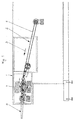
- a transport device forms a part a so-called slicing line, which is a cutting device for cutting food in slices, a weighing device for weighing slice portions, conveyor belts for transporting the cut product portions (aforementioned components not shown) contains.
- the cut line also has a switch designed as a conveyor belt 2, which is connected upstream of a shunting unit 4 in the transport direction (arrow 3).
- a further conveyor belt 5 with which the cut material portions be transferred to a packaging part of the slicing line.
- the shells and the cover film are made of roll-shaped material in the width of the maneuvering unit 4 or the conveyor belt 5 and are formed after the welding of the food portions cut into individual packs.
- the maneuvering unit 4 is responsible for the portions of the material to be cut coming from the cutting device if necessary to change their arrangement so that they match the desired Arrangement in the final packaging matches. For example, with help the cutting device of two material strands arranged side by side in the product shaft Always cut two slices at the same time, so they form on the tray table the cutting device two stacked or shingled disks Disk arrangements from. In this case, however, three such stacks or shingle arrangements should be used placed next to each other in a corresponding plastic tray and packed are, the shunting unit 4 has the task of a two-row product flow in to reshape a three-row.
- the switch 2 upstream of the shunting unit 4 is composed of two parallel to one another running and each consisting of a large number of individual tapes 6 Lanes 7a and 7b put together.
- the ends of both assigned to the shunting unit 4 Tracks 7a and 7b are independent of each other with the help of a carriage 8a and 8b adjustable perpendicular to the longitudinal axis of the transport device 1.
- the maneuvering unit 4 which is divided into three tracks, with portions of cut material to load them so that they hit the center of the web to be loaded.
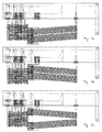
- 3a to 3c illustrate this connection in addition to the basic position according to FIG. 2 three further positions of the switch 2 with its two tracks 7a and 7b.
- the elasticity of the ribbons 6 consisting of a rubber-like plastic material is one Cross offset of the tracks 7a and 7b of the switch 2 while maintaining the vertical orientation of the respective deflection rollers for the tapes 6 and while maintaining their center distance possible by simple transverse displacement of a deflecting roller a certain length change of the ribbon 6 occurs and on the other hand a certain one Kink in connection to the existing grooves in the guide rollers for the Ribbon 6 takes place.
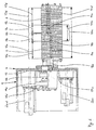
- the structure of the maneuvering unit 4 can be seen in detail from FIGS. 4 to 6.
- the Shunting unit 4 consists of a drive part 9 and a transport part 10, the surface of which 11 is formed by a plurality of ribbons 6. According to the principle of a conveyor belt a transport of cut material portions in the direction of arrow 12 is hereby possible.
- the Transport part 10 is in four parallel to each other and arranged side by side Paths 13a to 13d divided, each of which can be driven independently. Any of these Lanes is seen in the transport direction in a front section 13a / I to 13d / I and divided a rear portion 13a / II to 13d / II.
- each track 13a to 13d are driven by means of the same drive roller 14a to 14c, the width of the width 15a to 15d of the respective Path 13a to 13d corresponds.
- the drive rollers 14a to 14d are alternated Grooves for the ribbons 6 of the front and rear sections positioned side by side. For this reason, the horizontal density of the ribbons in the area of the deflection rollers 14a to 14d twice as large as in the rest of the surface 11 of the transport part 10 of the shunting unit 4.
- the drive rollers 14a and 14c are driven with the aid of a slight height offset having drive shafts 16a and 16c, which are each designed as hollow shafts, in the inside of which are the drive shafts, not visible in the figures, for the coaxially aligned drive shafts Drive rollers 14b and 14d run.
- the drive shaft 16a is connected to a wall 17 inside a housing 9 a pulley 18a is mounted, which is driven by a drive motor 20a via a belt 19a, which is a servo motor, can be driven.
- the shaft for the deflection roller 14b is passed through the pulley 18a and carries a pulley at its end 18b, which can be driven by a drive motor 20b by means of a belt 19b.
- the slight offset in the Height of the axes of rotation of the hollow drive shafts 16a and 16c results from the slightly inclined Course of the surface 11 of the transport part 10 of the maneuvering unit 4, which is the 1 can be seen from the front view.
- the widths 15b, 15c of the two are middle webs 13b, 13c about half the widths 15a, 15d of the outer webs 13a, 13d. In this way, there is approximately a three-way division of the total width 21 of all four lanes 13a to 13d when the two middle lanes 13b, 13c become a middle one Track 13bc with the width 15bc can be interconnected.
- the overall width 21 can be halved if, on the one hand, the webs 13a, 13b to form a path 13ab and, on the other hand, paths 13c and 13d to form a path 13c, d can be interconnected. After all, the independent operation of all four tracks 13a to 13d are possible, in which case the two middle tracks 13b and 13c have a comparatively small width.
- a use of the two combined Paths 13ab and 13cd on the one hand by synchronization of the drive motors 20a and 20b and 20c and 20d, on the other hand, is carried out if two-row or four-row (with two product stacks side by side per row). In this case the switch 2 maintain the position shown in Fig. 2, provided that on each track 7a, 7b Switch 2 a larger or two correspondingly smaller product stacks - from the cutting device and coming to the weighing device.
- the great advantage of the method and the shunting unit 4 according to the invention is that that changes in the number of disc stacks lying side by side in a pack or changes in the number of cut in the cutting device at the same time Disks do not require any conversion measures on the shunting unit 4. Rather can a changed division of the surface 11 of the transport part 10 of the maneuvering unit 4 alone by means of a modified control of the four drive motors 20a to 20d. This changed control is purely software, since the slicing line described here has a freely programmable computer control.
Abstract
Description
Die Erfindung betrifft ein Verfahren zum Betrieb einer Rangiereinheit einer Transportvorrichtung für Schneidgutportionen eines Lebensmittels, die von in Transportrichtung vorgelagerten und nachgelagerten Fördermitteln an die Rangiereinheit übergeben und von dieser weg geführt werden, wobei die Rangiereinheit eine Mehrzahl von parallel nebeneinander verlaufenden Bahnen aufweist, die jeweils von mindestens einem über Umlenkwalzen geführten Zugmittel gebildet sind, und wobei jede Bahn von mindestens einer separaten Antriebsrichtung angetrieben wird. Des weiteren betrifft die Erfindung eine Rangiereinheit einer Transportvorrichtung für Schneidgutportionen eines Lebensmittels, mit der das vorgenannte Verfahren ausführbar ist.The invention relates to a method for operating a maneuvering unit of a transport device for portions of food to be cut that are upstream of those in the transport direction and downstream funding to the shunting unit and led away from this are, the shunting unit a plurality of parallel to each other Has webs, each of at least one traction means guided over deflection rollers are formed, and wherein each path of at least one separate drive direction is driven. The invention further relates to a maneuvering unit of a transport device for portions of food to be cut using the above-mentioned method is executable.
Verfahren der vorgenannten Art sind allgemein bekannt, siehe z.B. EP-A-0 274 229, und werden insbesondere bei Aufschnittlinien, beispielsweise für Wurstwaren oder Käse, angewendet. Eine derartige Aufschnittlinie besteht aus einer Schneidvorrichtung, mit der das Lebensmittel in Form eines oder mehrerer Gutsstränge zugeführt wird. Mit Hilfe eines Abschneidemessers werden Scheiben von dem Lebensmittel abgeschnitten und auf ein Förderband übergeben. Die Ablage der einzelnen Scheiben erfolgt entweder stapelförmig oder geschindelt bzw. geschuppt, wobei mit Hilfe einer Wägeeinrichtung die Erzeugung von gleichgewichtigen Schneidgutportionen überwacht wird.Methods of the aforementioned type are generally known, see e.g. EP-A-0 274 229, and are used in particular with slicing lines, for example for sausages or cheese. Such a slicing line consists of a cutting device with which the food in the form of a or several crop strands is fed. With the help of a cutting knife, slices are made cut from the food and transferred to a conveyor belt. The filing of the individual Slices are either stacked or shingled or shingled, with With the help of a weighing device, the generation of equal portions of the material to be cut is monitored.
Im weiteren Verlauf des Förderbandes ist eine Weiche eingerichtet, mit der die beispielsweise eine Reihe der Schneidgutportionen abwechselnd auf die linke bzw. rechte Hälfte einer nachgeschalteten Rangiereinheit verteilt wird. Eine derartige Anordnung der Schneidgutportionen ist dann erforderlich, wenn diese in einer nachfolgenden Verpackungsmaschine zweireihig verpackt werden sollen. Die Verpackungsmaschinen derartiger Aufschnittlinien sind in der Regel so gestaltet, daß beispielsweise zwei nebeneinander angeordnete Schneidgutportionen in eine darin angepaßte, geprägte Kunststofform aus einer Unterfolie eingelegt werden, wobei nach dem Einlegen in die Schalen ein Zuschweißen der Packungen mit Hilfe einer Oberfolie erfolgt. Anschließend werden die endlos aneinander hängenden Packungen mit Hilfe von Schneidvorrichtungen voneinander zu Einzelpackungen getrennt. In the further course of the conveyor belt, a switch is set up, with which, for example a row of the cut portions alternately on the left or right half of a downstream Shunting unit is distributed. Such an arrangement of the cut portions is necessary if this is in two rows in a subsequent packaging machine should be packed. The packaging machines of such slicing lines are in the Usually designed in such a way that, for example, two cut material portions arranged side by side be inserted into an embossed plastic mold made of a lower film, wherein after insertion into the trays, the packs are sealed with the help of a top film he follows. Then the endlessly hanging packs with the help of Cutting devices separated from each other into individual packs.
Eine Rangiereinheit hat in einer derartigen Aufschnittlinie die Funktion, die Zahl der nebeneinander angeordneten Schneidgutportionen, wie sie bei einem Abschneidevorgang von der Schneidvorrichtung erzeugt werden, an die Zahl der Portionen anzupassen, die nebeneinander in einer Schale einer späteren Verpackung angeordnet sein sollen. Typischerweise werden bei einem Abschneidevorgang in der Schneidvorrichtung von einem, zwei, drei oder vier nebeneinander angeordneten Gutssträngen gleichzeitig jeweils eine Scheibe angeschnitten. Die Produktverpackungen weisen typischerweise ebenfalls einen, zwei, drei oder vier nebeneinander angeordnete Portionsstapel auf. Die Rangiereinheit hat die Aufgabe, die Zahl der Reihen, wie sie von der Schneidvorrichtung erzeugt werden, an die Zahl der Reihen anzupassen, wie sie in den fertigen Produktverpackungen vorhanden ist. Wird beispielsweise zweireihig abgeschnitten und soll eine Verpackung drei Schneidgutportionen nebeneinander aufweisen, d.h. eine dreireihige Verpackung stattfinden, so ist es Aufgabe der Rangiereinheit, die zweireihig ankommenden Schneidgutportionen so zu sortieren und zwischenzupuffern, daß eine getaktete dreireihige Abgabe an die nachfolgende, zum Verpackungsabschnitt der Aufschnittlinie führenden Transporteinrichtung erfolgen kann.A shunting unit has the function in such a slicing line, the number of side by side arranged portions of material to be cut, such as in a cutting process from the Cutting device are generated to adapt to the number of servings that are side by side should be arranged in a tray of a later packaging. Typically, at a cutting process in the cutter of one, two, three or four side by side arranged crop strands cut one slice at a time. The Product packaging typically also has one, two, three or four next to each other arranged portion stacks. The shunting unit has the task of as generated by the cutter to match the number of rows as it is in the finished product packaging. For example, it will be in two rows cut off and a package should have three portions of cut material next to each other, i.e. a three-row packaging take place, so it is the job of the shunting unit to do the two-row to sort incoming material portions and buffer them so that a timed three-row delivery to the subsequent, to the packaging section of the slicing line leading transport device can take place.
Im beschriebenen Fall weist die Rangiereinheit drei voneinander unabhängige, parallel zueinander angeordnete Bahnen auf, die jeweils von einer separaten Antriebseinrichtung antreibbar sind. Die von der Schneidvorrichtung kommenden, nebeneinander angeordneten Schneidgutstapel sind mit Hilfe einer Weiche rechtwinklig zur Transportrichtung versetzbar, wobei wahlweise eine Übergabe von einer der ankommenden Portionsbahnen auf eine äußere oder eine mittlere Bahn der Rangiereinheit möglich ist. Ein Querversatz der beiden Bahnen der Weiche ist - unabhängig voneinander - deshalb möglich, weil die Bahnen aus einer Vielzahl von schmalen Bändchen gebildet sind, die in Umlenk- bzw. Antriebswalzen gelagert sind, die an den Bändchenquerschnitt angepaßte Nuten aufweisen. Aufgrund der Elastizität der Bändchen läßt sich ein Querversatz der Weichenbahnen auf einfache Weise dadurch erzielen, daß die an die Rangiereinheit angrenzende Umlenkwalze der Weiche in Achsrichtung verschiebbar ist, wodurch ein leichtes Abknicken der Bändchen beim Verlassen der Walzen erfolgt.In the case described, the maneuvering unit has three mutually independent, parallel to each other arranged tracks, each of which can be driven by a separate drive device are. The stack of sliced goods coming from the cutting device, arranged side by side can be moved at right angles to the direction of transport using a switch, whereby optionally transfer from one of the incoming portion lanes to an outer or a middle path of the shunting unit is possible. A transverse offset of the two lanes of the Switching is possible - independently of one another - because the tracks consist of a large number are formed by narrow ribbons, which are mounted in deflection or drive rollers, the have grooves matched to the ribbon cross-section. Because of the elasticity of the ribbons a cross offset of the turnouts can be achieved in a simple manner in that the deflecting roller of the switch adjoining the maneuvering unit can be displaced in the axial direction is, which causes the ribbons to bend slightly when leaving the rollers.
Ein Nachteil der bekannten Rangiereinheiten ist darin zu sehen, daß diese mit erheblichem Aufwand umgerüstet werden müssen, wenn ein Wechsel in der Anzahl der gleichzeitig abgeschnittenen Produktscheiben bzw. ein Wechsel in der Anzahl der in der Verpackung nebeneinander angeordneten Produktstapel durchgeführt werden soll. In diesem Fall ist es nämlich nötig, anstelle von beispielsweise drei unabhängig voneinander antreibbaren Bahnen der Rangiereinheit derer zwei oder vier vorzusehen, wozu die Umlenk- bzw. Antriebswalzen ausgewechselt werden müssen. Jeder Wechsel im Verpackungs- bzw. Schneidbild verursacht daher einen erheblichen Umrüstungsaufwand, der mit hohen Kosten einhergeht. Außerdem ist eine derartige Umrüstung lediglich von Fachpersonal des Herstellers derartiger Rangiereinheiten durchführbar, wodurch die Flexibilität des Nutzers derartiger Aufschnittlinien, beispielsweise zum raschen Wechsel zwischen mehreren Verpackungsanordnungen, stark eingeschränkt wird.A disadvantage of the known shunting units can be seen in the fact that these with considerable Effort needs to be retooled when there is a change in the number of cut off at the same time Product slices or a change in the number of juxtaposed in the packaging arranged product stack to be performed. In this case it is necessary, instead of, for example, three independently drivable tracks of the Shunting unit to provide two or four, for which purpose the deflection or drive rollers replaced Need to become. Every change in the packaging or cutting pattern causes therefore a considerable changeover effort, which is associated with high costs. Besides, is such retrofitting only by specialist personnel from the manufacturer of such shunting units feasible, whereby the flexibility of the user of such slicing lines, for example for quickly changing between several packaging arrangements, severely restricted becomes.
Der Erfindung liegt die Aufgabe zugrunde, ein Verfahren zum Betrieb einer Rangiereinheit vorzuschlagen, bei der eine Anpassung an eine Veränderung der Anzahl der abgeschnitten Schneidgutscheiben bzw. der in einer Verpackung nebeneinander angeordneten Portionsstapel mit möglichst geringem Aufwand erfolgen kann. Gleichzeitig soll eine Rangiereinheit vorgeschlagen werden, mit der sich ein derartiges Verfahren einfach durchführen läßt.The invention has for its object a method for operating a shunting unit propose an adaptation to a change in the number of clipped Slices of sliced material or the portion stack arranged side by side in a packaging can be done with as little effort as possible. At the same time, a shunting unit be proposed with which such a method can be carried out easily.
Ausgehend von dem Verfahren der eingangs beschriebenen Art, wird diese Aufgabe erfindungsgemäß dadurch gelöst, daß eine Schneidgutportion von mindestens zwei Bahnen gleichzeitig transportiert wird.Starting from the method of the type described in the introduction, this object is achieved according to the invention solved in that a cutting material portion of at least two tracks at the same time is transported.
Eine derartige Vorgehensweise ermöglicht es, die Rangiereinheit in derart viele, parallel zueinander angeordnete Bahnen zu unterteilen, wie maximal Schneidgutportionen nebeneinander in einer Verpackung angeordnet sein sollen. Jede dieser Bahnen muß einen eigenen Antrieb besitzen, der unabhängig von den Antrieben der übrigen Bahnen ansteuerbar ist.Such a procedure enables the maneuvering unit to be divided into so many, parallel to one another to subdivide arranged tracks, such as maximum portions of cut material next to each other should be arranged in packaging. Each of these tracks has its own drive own, which can be controlled independently of the drives of the other railways.
Werden bei dem erfindungsgemäßen Verfahren ebenso viele Portionen nebeneinander in einer Verpackung angeordnet, wie Bahnen insgesamt nebeneinander in der Rangiereinheit vorhanden sind, so erfolgt beispielsweise im Falle einer einreihigen Anlieferung der Schneidgutportionen von der Schneidvorrichtung der Antrieb jeder einzelnen der Bahnen bei der Aufnahme der Portionen unabhängig von den anderen Bahnen. In the method according to the invention, as many servings are juxtaposed in one The packaging is arranged in the same way as the tracks in the shunting unit are, for example, in the case of single-row delivery of the cut portions from the cutting device the drive of each of the webs when recording the portions regardless of the other lanes.
Wird jedoch beispielsweise nur eine Anzahl von Portionsstapeln nebeneinander angestrebt, die der halben Anzahl der Bahnen der Rangiereinheit entspricht, so werden jeweils zwei benachbarte Bahnen synchron zueinander angetrieben, wodurch eine virtuelle Halbierung der voneinander unabhängigen Bahnen erfolgt. Beispielsweise kann eine Halbierung der Bahnanzahl durch eine Zwangskopplung benachbarter Bahnen erfolgen, die entweder auf mechanischem Wege mittels eines Kopplungselements oder auf steuerungstechnischem Wege durch entsprechend parallele Ansteuerung benachbarter Bahnen erfolgen kann.However, if, for example, only a number of portion stacks are sought next to one another, that corresponds to half the number of tracks in the shunting unit, then two adjacent ones Paths driven synchronously with each other, creating a virtual halving of the mutually independent tracks. For example, the number of webs can be halved by means of a forced coupling of adjacent tracks, which are either mechanical Paths by means of a coupling element or by means of control technology Corresponding parallel control of adjacent tracks can take place.
Durch die erfindungsgemäße Verfahrensweise wird beispielsweise der Austausch einer Umlenkwalze für eine breite Bahn gegen zwei Umlenkwalzen für entsprechend schmalere Bahnen überflüssig, da die Synchronisierung benachbarter Bahnen rein auf steuerungstechnischem Wege, d.h. bei computergesteuerten Aufschnittlinien allein durch eine entsprechende Software, erfolgt. Auch die Aufhebung der Synchronisation erfolgt in diesem Falle rein softwaremäßig. Hierdurch können die Kosten für einen Wechsel des Verpackungsbildes sowie der hierfür erforderliche Zeitaufwand drastisch reduziert werden. Auch ist kein Spezialpersonal erforderlich, das auf einen hardwaremäßigen Umbau der Rangiereinheit spezialisiert ist und typischerweise vom Hersteller derartiger Rangiereinheiten beigestellt werden muß.The procedure according to the invention makes it possible, for example, to replace a deflecting roller for a wide web against two deflection rollers for correspondingly narrower webs superfluous, since the synchronization of neighboring tracks is purely based on control technology Ways, i.e. in the case of computer-controlled slicing lines alone by means of a corresponding one Software. The synchronization is also canceled in this case purely by software. This can reduce the cost of changing the packaging image as well the time required for this can be drastically reduced. Also, there is no special staff required, which specializes in a hardware-related modification of the shunting unit and typically must be provided by the manufacturer of such shunting units.
Gemäß einer Ausgestaltung der Erfindung ist vorgesehen, daß die Geschwindigkeit jeder Bahn unabhängig geregelt wird.According to one embodiment of the invention it is provided that the speed of each Track is regulated independently.
Um beispielsweise leichte Fehler in der Ausrichtung eines länglichen Produktstapels ausgleichen zu können, ist es sinnvoll, daß die Geschwindigkeiten benachbarter Bahnen, mit denen gemeinsam dieselbe Schneidgutportion transportiert wird, zumindest temporär unterschiedlich groß sind, wodurch eine bewußte Veränderung der Ausrichtung, d.h. Verdrehung, eines Schneidgutstapels erreicht werden kann.For example, to compensate for slight errors in the alignment of an elongated stack of products To be able to, it makes sense that the speeds of neighboring tracks with which the same portion of cut material is transported together, at least temporarily differently are large, causing a deliberate change in orientation, i.e. Twisting, one Stack of cuttings can be achieved.
Eine Rangiereinheit einer Transportvorrichtung für Schneidgutportionen eines Lebensmittels weist eine Mehrzahl von parallel nebeneinander verlaufenden Bahnen auf, die jeweils von mindestens einem über Umlenkwalzen geführten Zugmittel gebildet sind und jeweils einerseits von einem in Transportrichtung der Rangiereinheit vorgelagerten Fördermittel mit Schneidgutportionen beschickbar sind, die andererseits an ein nachgelagertes Fördermittel abgebbar sind, wobei jede Bahn von einer separaten Antriebseinrichtung antreibbar ist, und ist erfindungsgemäß dadurch gekennzeichnet, daß vier Bahnen vorhanden sind, von denen die beiden mittleren Bahnen jeweils eine Breite aufweisen, die der halben Breite der beiden äußeren Bahnen entspricht.A maneuvering unit of a transport device for portions of food to be cut has a plurality of tracks running in parallel next to each other, each of at least one traction means guided over deflection rollers are formed and in each case on the one hand from an upstream conveyor in the direction of transport Portions of the material to be cut can be loaded, which, on the other hand, are connected to a downstream conveyor are dispensable, each web being drivable by a separate drive device, and is characterized according to the invention in that there are four tracks, of which the the two middle webs each have a width that is half the width of the two outer ones Orbits.
Eine derartige Aufteilung der Gesamtbreite der Rangiereinheit auf die vier Bahnen erlaubt in sehr vorteilhafter Weise auch ein Verpacken von drei Schneidgutportionen nebeneinander, wozu ein unabhängiger Antrieb von drei Bahnen erforderlich ist. In diesem Fall werden die beiden mittleren Bahnen zwangssynchronisiert, wodurch sich drei in ihrer Breite identische Einzelbahnen ergeben. Soll hingegen zweireihig bzw. vierreihig verpackt werden, so werden jeweils eine äußere und die benachbarte mittlere Bahn synchron betrieben, wodurch sich zwei gleich breite Bahnen ergeben, die die Hälfte der Gesamtbreite der Rangiereinheit ausmachen. Jede dieser beiden Bahnen kann gleichzeitig mit zwei kleineren oder vier einem größeren Schneidgutstapel beschickt werden. Theoretisch ist auch der unabhängige Betrieb aller vier Bahnen möglich, wobei in diesem Fall die mittleren Bahnen jedoch nur ungefähr die halbe Breite der beiden äußeren Bahnen aufweisen.Such a division of the total width of the shunting unit over the four tracks allows in very advantageously also packaging three portions of cut material next to one another, which requires an independent drive of three lanes. In this case, the the two middle tracks are synchronized, which means that three are identical in width Single tracks result. If, on the other hand, two or four rows are to be packaged, then one outer and the adjacent middle track operated synchronously, whereby two result in tracks of equal width that make up half of the total width of the shunting unit. Each of these two tracks can be used simultaneously with two smaller or four one larger Stacks of cut goods are loaded. Theoretically, the independent operation of all four is also Lanes possible, but in this case the middle lanes are only about half Have width of the two outer panels.
Gemäß einer Ausgestaltung der erfindungsgemäßen Rangiereinheit ist vorgesehen, daß Antriebswalzen jeweils einer äußeren Bahn und der benachbarten mittleren Bahn koaxial zueinander angeordnet sind. Vorteilhafterweise ist dabei eine Antriebswelle einer Antriebswalze einer mittleren Bahn durch die hohl ausgeführte Antriebswalze der benachbarten äußeren Bahn geführt. Mit Hilfe eines derartigen Hohlwellenprinzips lassen sich benachbarte Bahnen an miteinander fluchtenden Stellen mit ihrem Antrieb versehen.According to an embodiment of the maneuvering unit according to the invention it is provided that drive rollers one outer track and the adjacent middle track coaxial with each other are arranged. Advantageously, a drive shaft of a drive roller a middle path through the hollow drive roller of the adjacent outer Track led. With the help of such a hollow shaft principle, adjacent tracks can be created Provide their drive at points in line with one another.
Eine zu bevorzugende Antriebsform für die Bahnen besteht darin, daß eine hohl ausgeführte Antriebswalze und eine durch diese geführte Antriebswelle jeweils mit einer Riemenscheibe für einen von einem Servomotor angetriebenen Flachriemen versehen ist. Mit Hilfe derartiger Servomotoren lassen sich die einzelnen Bahnen extrem präzise ansteuern. Der Gleichlauf benachbarter Bahnen kann daher extrem gut sein. Die Gefahr unbeabsichtigter Verdrehungen von Schneidgutstapeln im Verlauf ihres Transports durch die Rangiereinheit ist hierdurch praktisch ausgeschlossen. Dies ist nicht zuletzt auch auf die Verwendung von Servomotoren zurückzuführen, mit denen sich sehr geringe Drehzahlabweichungen realisieren lassen.A preferred form of drive for the webs is that of a hollow one Drive roller and a drive shaft guided through this each with a pulley for a flat belt driven by a servo motor. With the help of such Servomotors can be controlled extremely precisely on the individual webs. The synchronization Adjacent courses can therefore be extremely good. The risk of unintentional twisting of stacks of cut material in the course of their transport through the maneuvering unit is hereby practically excluded. This is not least due to the use of servo motors with which very low speed deviations can be realized.
Um den benötigten Bauraum für die Motoren zu schaffen, wird nach der Erfindung noch vorgeschlagen, daß die hohl ausgeführten Antriebswalzen in horizontale Richtung versetzt zueinander angeordnet sind und sich die Servomotoren alle auf derselben Seite der Rangiereinheit befinden.In order to create the space required for the motors, the invention also proposes that the hollow drive rollers offset from each other in the horizontal direction are arranged and the servomotors are all on the same side of the shunting unit are located.
Wenn die Servomotoren, die auf koaxial zueinander angeordnete Riemenscheiben wirken, jeweils vertikal übereinander angeordnet sind, kann eine Motoranordnung ungefähr auf den Eckpunkten eines Quadrats gewählt werden.If the servomotors, which act on pulleys arranged coaxially to one another, are arranged vertically one above the other, a motor arrangement can approximately on the Corner points of a square can be chosen.
Bei einer bevorzugten Ausführungsform der erfindungsgemäßen Rangiereinheit besteht jede Bahn aus einer Mehrzahl von parallel zueinander verlaufenden und äquidistant zueinander angeordneten Bändchen oder Riemchen. In diesem Fall ist es möglich, jede Bahn aus zwei in Transportrichtung hintereinander angeordneten Abschnitten aufzubauen, die jeweils von einer gemeinsamen Antriebswalze antreibbar sind und wobei auf der Antriebsseite jeweils abwechselnd ein Bändchen eines ersten Abschnitts und ein Bändchen eines zweiten Abschnitts angeordnet ist. Ein Spalt zwischen den Abschnitten wird hierdurch vermieden. Auf diese Weise lassen sich die Antriebswalzen - in Transportrichtung der Rangiereinheit betrachtet - in deren Mittelbereich plazieren, wobei aufgrund der Aufteilung in zwei Abschnitte für jeden Abschnitt im Bereich der Antriebswalze ein hinreichend großer Umschlingungswinkel gegeben ist, so daß eine problemlose Krafteinleitung über eine Reibschlußverbindung möglich ist. Die mittige Anordnung der Antriebswalzen bietet den Vorteil, daß hinreichend Raum für die Anordnung der Antriebsmotoren besteht, ohne daß diese über die Länge der Rangiereinheit vorstehen würden.In a preferred embodiment of the maneuvering unit according to the invention, there is each Web of a plurality of parallel and equidistant to each other arranged ribbon or straps. In this case it is possible to make each lane out of two Transport direction to build up consecutive sections, each of one common drive roller are drivable and alternately on the drive side a ribbon of a first section and a ribbon of a second section are arranged is. This avoids a gap between the sections. In this way the drive rollers - viewed in the transport direction of the shunting unit - can be Place middle section, due to the division into two sections for each section given a sufficiently large wrap angle in the area of the drive roller is, so that a problem-free introduction of force via a frictional connection is possible. The Central arrangement of the drive rollers offers the advantage that there is sufficient space for the arrangement of the drive motors, without this over the length of the maneuvering unit would preside.
Das erfindungsgemäße Verfahren wird nachfolgend anhand eines Ausführungsbeispiels einer Rangiereinheit nach der Erfindung, die in der Zeichnung dargestellt ist, näher erläutert. Es zeigt:
- Fig. 1
- eine Vorderansicht einer Transportvorrichtung als Teileiner Aufschnittlinie;
- Fig. 2
- eine Draufsicht auf die Transportvorrichtung gemäß Fig. 1;
- Fig. 3a bis 3c
- wie Fig. 2, jedoch in unterschiedlichen Stellungen einer Weiche;
- Fig. 4
- eine perspektivische Ansicht einer Rangiereinheit;
- Fig. 5
- eine Draufsicht auf die Rangiereinheit gemäß Fig. 4;
- Fig. 6
- eine Seitenansicht der Rangiereinheit gemäß Fig. 4 und
- Fig. 7
- eine Rückansicht der Rangiereinheit gemäß Fig. 4.
- Fig. 1
- a front view of a transport device as part of a slicing line;
- Fig. 2
- a plan view of the transport device of FIG. 1;
- 3a to 3c
- like FIG. 2, but in different positions of a switch;
- Fig. 4
- a perspective view of a maneuvering unit;
- Fig. 5
- a plan view of the maneuvering unit according to FIG. 4;
- Fig. 6
- a side view of the maneuvering unit according to FIGS. 4 and
- Fig. 7
- a rear view of the maneuvering unit according to FIG. 4.
Eine in den Fig. 1 und 2 insgesamt mit 1 bezeichnete Transporteinrichtung bildet einen Teil
einer sogenannten Aufschnittlinie, die eine Schneideinrichtung zum Schneiden von Lebensmitteln
in Scheiben, eine Wägeeinrichtung zum Abwiegen von Scheibenportionen, Transportbänder
zum Transport der Schneidgutportionen (vorgenannte Komponenten nicht dargestellt)
enthält. Die Aufschnittlinie weist des weiteren eine als Förderband ausgebildete Weiche
2 auf, die in Transportrichtung (Pfeil 3) einer Rangiereinheit 4 vorgeschaltet ist. An die
Rangiereinheit 4 schließt sich ein weiteres Förderband 5 an, mit dem die Schneidgutportionen
in einen verpackungstechnischen Teil der Aufschnittlinie überführt werden. Dort werden die
Portionen in vorgeformte geprägte Schalen aus Kunststoffunterfolie eingelegt und anschließend
mit einer Deckfolie unter Luftabschluß oder unter einer Schutzatmosphäre verschlossen.
Die Schalen und die Deckfolie werden aus rollenförmigem Material in der Breite der Rangiereinheit
4 bzw. des Förderbandes 5 gebildet und werden nach dem Einschweißen der Lebensmittelportionen
zu einzelnen Packungen auseinandergeschnitten. A transport device, generally designated 1 in FIGS. 1 and 2, forms a part
a so-called slicing line, which is a cutting device for cutting food
in slices, a weighing device for weighing slice portions, conveyor belts
for transporting the cut product portions (aforementioned components not shown)
contains. The cut line also has a switch designed as a
Die Rangiereinheit 4 hat die Aufgabe, die von der Schneideinrichtung kommenden Schneidgutportionen
erforderlichenfalls in ihrer Anordnung so zu verändern, daß sie mit der gewünschten
Anordnung in der Endverpackung übereinstimmt. Werden beispielsweise mit Hilfe
der Schneideinrichtung von zwei nebeneinander in dem Produktschacht angeordneten Gutssträngen
immer zwei Scheiben gleichzeitig abgeschnitten, so bilden sich auf dem Ablagetisch
der Schneideinrichtung zwei nebeneinander angeordnete Scheibenstapel bzw. geschindelte
Scheibenanordnungen aus. Sollen in diesem Fall jedoch drei derartige Stapel oder Schindelanordnungen
nebeneinander in eine entsprechende Kunststoffschale eingelegt und verpackt
werden, so kommt der Rangiereinheit 4 die Aufgabe zu, einen zweireihigen Produktstrom in
einen dreireihigen umzuformen.The
Zu diesem Zweck ist die der Rangiereinheit 4 vorgeschaltete Weiche 2 aus zwei parallel zueinander
verlaufenden und jeweils aus einer Vielzahl von einzelnen Bändchen 6 bestehenden
Bahnen 7a und 7b zusammengesetzt. Die der Rangiereinheit 4 zugeordneten Enden beider
Bahnen 7a und 7b sind unabhängig voneinander jeweils mit Hilfe eines Schlittens 8a und 8b
senkrecht zur Längsachse der Transporteinrichtung 1 verstellbar. Auf diese Weise ist es möglich,
beispielsweise die in drei Bahnen unterteilte Rangiereinheit 4 so mit Schneidgutportionen
zu beschicken, daß diese mittig auf die jeweils zu beaufschlagende Bahn auftreffen. In
diesem Zusammenhang verdeutlichen die Fig. 3a bis 3c neben der Grundstellung gemäß Fig.
2 drei weitere Stellungen der Weiche 2 mit ihren beiden Bahnen 7a und 7b. Aufgrund der
Elastizität der aus einem gummiartigen Kunststoffmaterial bestehenden Bändchen 6 ist ein
Querversatz der Bahnen 7a und 7b der Weiche 2 unter Beibehaltung der senkrechten Ausrichtung
der jeweiligen Umlenkwalzen für die Bändchen 6 und unter Beibehaltung deren Achsabstands
durch einfache Querverschiebung jeweils einer Umlenkwalze möglich, wobei zum
einen eine gewisse Längenänderung der Bändchen 6 eintritt und zum anderen eine gewisse
Abknickung im Anschluß an die in den Umlenkwalzen vorhandenen Aufnahmenuten für die
Bändchen 6 stattfindet.For this purpose, the
Aus den Fig. 4 bis 6 läßt sich der Aufbau der Rangiereinheit 4 im einzelnen entnehmen. Die
Rangiereinheit 4 besteht aus einem Antriebsteil 9 und einem Transportteil 10, dessen Oberfläche
11 von einer Vielzahl von Bändchen 6 gebildet wird. Nach dem Prinzip eines Förderbandes
ist hiermit ein Transport von Schneidgutportionen in Richtung des Pfeils 12 möglich. Das
Transportteil 10 ist in vier parallel zueinander verlaufende und nebeneinander angeordnete
Bahnen 13a bis 13d unterteilt, die jeweils unabhängig voneinander antreibbar sind. Jede dieser
Bahnen ist in Transportrichtung gesehen in einen vorderen Abschnitt 13a/I bis 13d/I und
einen hinteren Abschnitt 13a/II bis 13d/II unterteilt. Während im Fall der Bahnen 13a und 13b
die vorderen Abschnitte 13a/I und 13b/I eine größere Länge besitzen als die jeweils hinteren
Abschnitte 13a/II und 13b/II, ist dies bei den Bahnen 13c und 13d genau andersherum.The structure of the
Der Antrieb der vorderen und der hinteren Abschnitte jeder Bahn 13a bis 13d erfolgt mit Hilfe
jeweils derselben Antriebswalze 14a bis 14c, deren Breite der Breite 15a bis 15d der jeweiligen
Bahn 13a bis 13d entspricht. In jeder der Antriebswalzen 14a bis 14d sind abwechselnd
Nuten für die Bändchen 6 der vorderen und der hinteren Abschnitte nebeneinander positioniert.
Aus diesem Grunde ist die horizontale Dichte der Bändchen im Bereich der Umlenkwalzen
14a bis 14d doppelt so groß wie im übrigen Bereich der Oberfläche 11 des Transportteils
10 der Rangiereinheit 4.The front and rear sections of each
Der Antrieb der Antriebswalzen 14a und 14c erfolgt mit Hilfe der einen leichten Höhenversatz
aufweisenden Antriebswellen 16a und 16c, die jeweils als Hohlwellen ausgeführt sind, in
deren Inneren die in den Figuren nicht sichtbaren Antriebswellen für die koaxial hierzu ausgerichteten
Antriebswalzen 14b und 14d verlaufen.The
Auf der Antriebswelle 16a ist im Anschluß an eine Wand 17 im Inneren eines Gehäuses 9
eine Riemenscheibe 18a montiert, die über einen Riemen 19a von einem Antriebsmotor 20a,
bei dem es sich um einen Servomotor handelt, antreibbar ist. Die Welle für die Umlenkwalze
14b ist durch die Riemenscheibe 18a hindurchgeführt und trägt an ihrem Ende eine Riemenscheibe
18b, die mittels eines Riemens 19b von einem Antriebsmotor 20b antreibbar ist. Auf
diese Weise ergibt sich eine Anordnung der Antriebsmotoren 20a bis 20d, bei der deren
Drehachsen ungefähr die Eckpunkte eines Rechtecks markieren. Der leichte Versatz in der
Höhe der Drehachsen der hohlen Antriebswellen 16a und 16c ergibt sich aus dem leicht geneigten
Verlauf der Oberfläche 11 des Transportteils 10 der Rangiereinheit 4, die sich der
Vorderansicht gemäß Fig. 1 entnehmen läßt. The
Wie insbesondere aus den Fig. 5 und 6 ersichtlich ist, betragen die Breiten 15b, 15c der beiden
mittleren Bahnen 13b, 13c ungefähr die Hälfte der Breiten 15a, 15d der äußeren Bahnen
13a, 13d. Auf diese Weise ergibt sich ungefähr eine Dreiteilung der Gesamtbreite 21 sämtlicher
vier Bahnen 13a bis 13d, wenn die beiden mittleren Bahnen 13b, 13c zu einer mittleren
Bahn 13bc mit der Breite 15bc zusammengeschaltet werden.As can be seen in particular from FIGS. 5 and 6, the
Hingegen läßt sich eine Halbierung der Gesamtbreite 21 erreichen, wenn einerseits die Bahnen
13a, 13b zu einer Bahn 13ab und andererseits die Bahnen 13c und 13d zu einer Bahn
13c,d zusammengeschaltet werden. Schließlich ist auch der unabhängige Betrieb von sämtlichen
vier Bahnen 13a bis 13d möglich, wobei in diesem Fall die beiden mittleren Bahnen 13b
und 13c eine vergleichsweise geringe Breite aufweisen. Eine Nutzung der beiden kombinierten
Bahnen 13ab und 13cd durch Synchronisation der Antriebsmotoren 20a und 20b einerseits
und 20c und 20d andererseits wird dann durchgeführt, wenn zweireihig oder auch vierreihig
(mit zwei Produktstapeln nebeneinander pro Reihe) gepackt werden soll. In diesem Fall kann
die Weiche 2 die in Fig. 2 dargestellte Stellung beibehalten, sofern auf jeder Bahn 7a, 7b der
Weiche 2 ein größerer oder zwei entsprechend kleinere Produktstapel - von der Schneideeinrichtung
und der Wägeeinrichtung kommend - abgelegt werden.On the other hand, the
Komplizierter ist der Fall des zweireihigen Schneidens, bei dem auf jeder Bahn 7a, 7b der
Weiche 2 ein Scheibenpaket zur Ablage gelangt, und des anschließenden dreireihigen Verpackens
in der Verpackungsmaschine. In diesem Fall müssen die jeweils von der Weiche 2 an
die Rangiereinheit 4 übergebenen Produktstapel abwechselnd entweder an die Bahnen 13a
und 13bc (Fig. 3a), die Bahnen 13bc und 13d (Fig. 3b) und die Bahnen 13a und 13d übergeben
werden, um während mehrerer Zyklen auf der Oberfläche 11 der Rangiereinheit 4 die für
die Verpackungsmaschine benötigte Stapelanordnung zu erzeugen. In dem von der Verpakkungsmaschine
vorgegebenen Takt muß von der Rangiereinheit 4 ein Paket von drei nebeneinander
angeordneten Scheibenstapeln erzeugt und zu demselben Zeitpunkt an die anschließende
Fördereinrichtung 5 übergeben werden. The case of double-row cutting is more complicated, in which on each path 7a, 7b
Turnout 2 a disc package comes to rest, and the subsequent three-row packaging
in the packaging machine. In this case, they must start at
Der große Vorteil des Verfahrens und der Rangiereinheit 4 gemäß der Erfindung besteht darin,
daß Änderungen in der Anzahl der nebeneinander in einer Packung liegenden Scheibenstapel
bzw. Änderungen in der Anzahl der zeitgleich in der Schneideinrichtung abgeschnittenen
Scheiben keinerlei Umbaumaßnahmen an der Rangiereinheit 4 erfordern. Vielmehr kann
eine geänderte Aufteilung der Oberfläche 11 des Transportteils 10 der Rangiereinheit 4 allein
im Wege einer geänderten Ansteuerung der vier Antriebsmotoren 20a bis 20d erfolgen. Diese
geänderte Ansteuerung erfolgt rein softwaremäßig, da die hier beschriebene Aufschnittlinie
über eine frei programmierbare Rechnersteuerung verfügt.The great advantage of the method and the
Claims (11)
- Method for operating a distributing unit (4) of a conveyor (1) for sliced foodstuffs which are passed from conveying means positioned ahead (2) and behind (5), as seen in the transport direction, to the distributing unit (4) and away from the latter, and the distributing unit comprises a plurality of parallel belts (13a-d) which are formed by at least one pulling means which is guided via diverting rollers (15a-d), and each belt is driven by at least one separate drive (20a-d), characterised in that sliced foodstuff is transported simultaneously by at least two belts.
- Method according to Claim 1, characterised in that the speed of each belt is controlled independently.
- Method according to Claim 1 or 2, characterised in that speeds of adjacent belts, by means of which the same sliced foodstuff is jointly transported, differ at least temporarily.
- Distributing unit (4) of a conveyor (1) for sliced foodstuffs, and the distributing unit (4) comprises a plurality of belts (13a to 13d) which run parallel alongside each other and which are formed by at least one pulling means guided via diverting rollers (15a to 15d) and which are delivered sliced foodstuffs on the one hand by a conveying means upstream of the distributing unit (4), as seen in the transport direction, and which are on the other side passed on to a downstream conveying means (5), and each belt (13a to 13d) is driven by a separate drive (20a-d), characterised in that there are four belts (13a to 13d) of which the two middle belts (13b and 13c) have one respective width (15b, 15c) which equals approximately half the width (15a, 15d) of the two outer belts (13a, 13d).
- Distributing unit according to Claim 4, characterised in that the drive rollers (16a, 16b and 16c, 16d) are arranged coaxially relative to an outer belt (13a, 13d) and the adjacent middle belt (13b, 13c).
- Distributing unit according to Claim 5, characterised in that a driveshaft of a drive roller (14b, 14c) of a middle belt (13b, 13c) is passed through a drive roller (14a, 14d) of tubular design of the adjacent outer belt (13a, 13d).
- Distributing unit according to Claim 6, characterised in that a tubular drive roller (14a, 14c) and a driveshaft which is passed through the latter are respectively provided with a belt pulley (18a to 18d) for a flat belt (19) which is driven by a servo motor.
- Distributing unit according to Claim 7, characterised in that the tubular drive rollers (14a, 14c) are transposed in the horizontal direction, and the servo motors are all on the same side of the distributing unit (4).
- Distributing unit according to Claim 8, characterised in that the servo motors which act on belt pulleys (18a, 18b and 18c, 18d), which are arranged coaxially relative to each other, are respectively arranged vertically above one another.
- Distributing unit according to one of Claims 4 to 9, characterised in that each belt (13a to 13d) is composed of a plurality of little bands (6) or little belts of a rubber-elastic material which extend parallel and equidistantly relative to each other.
- Distributing unit according to Claim 10, characterised in that each belt (13a to 13d) is composed of two sections (13a/I and 13a/II, 13b/I and 13b/II, 13c/I and 13c/II, 13d/I and 13d/II) which are respectively driven by a common driveshaft (14a to 14d), and on the drive roller (14a to 14d) is respectively alternately arranged a little band (6) of a first section (13a/I, 13b/I, 13c/I, 13d/I) and a little band (6) of a second section (13a/II, 13b/II, 13c/II, 13d/II).
Applications Claiming Priority (2)
| Application Number | Priority Date | Filing Date | Title |
|---|---|---|---|
| DE10018568 | 2000-04-14 | ||
| DE10018568A DE10018568C2 (en) | 2000-04-14 | 2000-04-14 | Method for operating a maneuvering unit of a transport device for portions of food to be cut and maneuvering unit |
Publications (2)
| Publication Number | Publication Date |
|---|---|
| EP1149782A1 EP1149782A1 (en) | 2001-10-31 |
| EP1149782B1 true EP1149782B1 (en) | 2002-12-11 |
Family
ID=7638774
Family Applications (1)
| Application Number | Title | Priority Date | Filing Date |
|---|---|---|---|
| EP01108660A Expired - Lifetime EP1149782B1 (en) | 2000-04-14 | 2001-04-06 | Method for the use of a distributing device of a conveyor for sliced foodstuffs and distributing device |
Country Status (4)
| Country | Link |
|---|---|
| EP (1) | EP1149782B1 (en) |
| AT (1) | ATE229466T1 (en) |
| DE (2) | DE10018568C2 (en) |
| ES (1) | ES2188574T3 (en) |
Cited By (1)
| Publication number | Priority date | Publication date | Assignee | Title |
|---|---|---|---|---|
| EP2522474A1 (en) | 2011-05-10 | 2012-11-14 | Bizerba GmbH & Co. KG | Cutting machine |
Families Citing this family (3)
| Publication number | Priority date | Publication date | Assignee | Title |
|---|---|---|---|---|
| US20090188357A1 (en) † | 2007-10-22 | 2009-07-30 | Lindee Scott A | Information Carrier System for a Food Article Slicing Machine |
| DE102012109247A1 (en) | 2012-09-28 | 2014-04-03 | Gea Food Solutions Germany Gmbh | Apparatus and method for the continuous production of portions |
| DE102014111330A1 (en) * | 2014-08-08 | 2016-02-11 | Weber Maschinenbau Gmbh Breidenbach | Device for distributing a stream of products |
Family Cites Families (6)
| Publication number | Priority date | Publication date | Assignee | Title |
|---|---|---|---|---|
| EP0274229B1 (en) * | 1986-12-10 | 1991-10-02 | Thurne Engineering Co Ltd | Conveyor system |
| GB8810057D0 (en) * | 1988-04-28 | 1988-06-02 | Thurne Eng Co Ltd | Conveyor system |
| DE4111837A1 (en) * | 1991-04-11 | 1992-10-15 | Dixie Union Verpackungen Gmbh | DEVICE FOR TRANSPORTING SENSITIVE GOODS |
| DE4220602C2 (en) * | 1992-04-29 | 2001-02-22 | Maschb Heinrich Hajek Gmbh & C | Cutting machine for cutting food products with a length-adjustable conveyor belt |
| DE19617187A1 (en) * | 1996-04-29 | 1997-10-30 | Biforce Anstalt | Method for distributing product flow such as foods in high-speed slicing machines |
| GB9611465D0 (en) * | 1996-06-01 | 1996-08-07 | Thurne Eng Co Ltd | Slicing of products |
-
2000
- 2000-04-14 DE DE10018568A patent/DE10018568C2/en not_active Expired - Lifetime
-
2001
- 2001-04-06 AT AT01108660T patent/ATE229466T1/en active
- 2001-04-06 ES ES01108660T patent/ES2188574T3/en not_active Expired - Lifetime
- 2001-04-06 EP EP01108660A patent/EP1149782B1/en not_active Expired - Lifetime
- 2001-04-06 DE DE50100069T patent/DE50100069D1/en not_active Expired - Lifetime
Cited By (2)
| Publication number | Priority date | Publication date | Assignee | Title |
|---|---|---|---|---|
| EP2522474A1 (en) | 2011-05-10 | 2012-11-14 | Bizerba GmbH & Co. KG | Cutting machine |
| DE102011101101A1 (en) | 2011-05-10 | 2014-01-30 | Bizerba Gmbh & Co Kg | cutting machine |
Also Published As
| Publication number | Publication date |
|---|---|
| DE10018568C2 (en) | 2002-04-11 |
| DE10018568A1 (en) | 2001-10-25 |
| EP1149782A1 (en) | 2001-10-31 |
| ATE229466T1 (en) | 2002-12-15 |
| DE50100069D1 (en) | 2003-01-23 |
| ES2188574T3 (en) | 2003-07-01 |
Similar Documents
| Publication | Publication Date | Title |
|---|---|---|
| EP0403901B2 (en) | Sorting device for cut flat elements | |
| DE69934375T2 (en) | Plant for producing and packaging roll-shaped objects | |
| DE4207725A1 (en) | Continuous packaging system for groups of goods - has support elements for front and rear of each group in running direction during entire process. | |
| DE3008842C2 (en) | ||
| DE102009019512A1 (en) | Plant for the production of slabs of wood laths and process for the production of such slabs | |
| DE60112697T2 (en) | Device for receiving and ejecting flat objects in a machine for their processing | |
| DE2745693C2 (en) | Device for feeding flaked corrugated cardboard sheets to a stacking device | |
| DE4204987A1 (en) | DEVICE FOR CUTTING AND STACKING PRODUCTS PACKED IN A FILM TUBE | |
| DE4013116A1 (en) | Stacking process for flat cardboard blanks - produces gap in overlapping flow for undisturbed removal of stack | |
| EP1291305B1 (en) | Distribution device | |
| DE2702724C2 (en) | Device for sorting and storing blanks in panel dividing systems | |
| EP1149782B1 (en) | Method for the use of a distributing device of a conveyor for sliced foodstuffs and distributing device | |
| DE1929600C3 (en) | Device for transferring workpieces, which are continuously moved forward in a row in the longitudinal direction and intended for the production of sacks, into a continuous conveyance in the transverse direction | |
| EP3502017A1 (en) | Device and method for handling food portions with a rotating device | |
| EP0820943B1 (en) | Device for changing number of conveying streams of food piles | |
| DE3604870A1 (en) | METHOD AND DEVICE FOR STACKING CORRUGATED CARDBOARD SECTIONS ON AT LEAST TWO PACKS ARRANGED TOGETHER | |
| EP1293453B1 (en) | Apparatus for making palletizable layers | |
| WO2006072570A1 (en) | Plant for the production and separation of wafer pieces | |
| DE19715613C1 (en) | Process for the production of groups to be packaged from cylindrical products nesting side by side in several product rows | |
| EP1293432A1 (en) | Rotating station for containers | |
| EP1559669A1 (en) | Method, arrangement and device for the transverse transport of reams | |
| DE4202254A1 (en) | METHOD FOR SUPPLYING PAPERS, TISSUE, NONWOVEN OR THE LIKE TO A FOLDING MACHINE FOR PRODUCING FOLDING SECTIONS FOLDED IN THE LATERAL DIRECTION, AND FOR DELIVERING THE CUT-UP CUTTINGS IN THE PRE-CUTTING SECTION | |
| CH442958A (en) | Device for handling sheets | |
| EP1707520B1 (en) | Continuously operating cross cutter | |
| EP0457720B1 (en) | Feeding device for a machine for assembling veneer sheets to form a continuous veneer strip |
Legal Events
| Date | Code | Title | Description |
|---|---|---|---|
| PUAI | Public reference made under article 153(3) epc to a published international application that has entered the european phase |
Free format text: ORIGINAL CODE: 0009012 |
|
| AK | Designated contracting states |
Kind code of ref document: A1 Designated state(s): AT BE CH CY DE DK ES FI FR GB GR IE IT LI LU MC NL PT SE TR |
|
| AX | Request for extension of the european patent |
Free format text: AL;LT;LV;MK;RO;SI |
|
| 17P | Request for examination filed |
Effective date: 20011107 |
|
| GRAG | Despatch of communication of intention to grant |
Free format text: ORIGINAL CODE: EPIDOS AGRA |
|
| GRAG | Despatch of communication of intention to grant |
Free format text: ORIGINAL CODE: EPIDOS AGRA |
|
| 17Q | First examination report despatched |
Effective date: 20020426 |
|
| GRAG | Despatch of communication of intention to grant |
Free format text: ORIGINAL CODE: EPIDOS AGRA |
|
| GRAH | Despatch of communication of intention to grant a patent |
Free format text: ORIGINAL CODE: EPIDOS IGRA |
|
| AKX | Designation fees paid |
Free format text: AT BE CH CY DE DK ES FI FR GB GR IE IT LI LU MC NL PT SE TR |
|
| GRAH | Despatch of communication of intention to grant a patent |
Free format text: ORIGINAL CODE: EPIDOS IGRA |
|
| GRAA | (expected) grant |
Free format text: ORIGINAL CODE: 0009210 |
|
| AK | Designated contracting states |
Kind code of ref document: B1 Designated state(s): AT BE CH CY DE DK ES FI FR GB GR IE IT LI LU MC NL PT SE TR |
|
| PG25 | Lapsed in a contracting state [announced via postgrant information from national office to epo] |
Ref country code: IE Free format text: LAPSE BECAUSE OF FAILURE TO SUBMIT A TRANSLATION OF THE DESCRIPTION OR TO PAY THE FEE WITHIN THE PRESCRIBED TIME-LIMIT Effective date: 20021211 Ref country code: NL Free format text: LAPSE BECAUSE OF FAILURE TO SUBMIT A TRANSLATION OF THE DESCRIPTION OR TO PAY THE FEE WITHIN THE PRESCRIBED TIME-LIMIT Effective date: 20021211 Ref country code: GR Free format text: LAPSE BECAUSE OF FAILURE TO SUBMIT A TRANSLATION OF THE DESCRIPTION OR TO PAY THE FEE WITHIN THE PRESCRIBED TIME-LIMIT Effective date: 20021211 Ref country code: FI Free format text: LAPSE BECAUSE OF FAILURE TO SUBMIT A TRANSLATION OF THE DESCRIPTION OR TO PAY THE FEE WITHIN THE PRESCRIBED TIME-LIMIT Effective date: 20021211 Ref country code: TR Free format text: LAPSE BECAUSE OF FAILURE TO SUBMIT A TRANSLATION OF THE DESCRIPTION OR TO PAY THE FEE WITHIN THE PRESCRIBED TIME-LIMIT Effective date: 20021211 |
|
| REF | Corresponds to: |
Ref document number: 229466 Country of ref document: AT Date of ref document: 20021215 Kind code of ref document: T |
|
| REG | Reference to a national code |
Ref country code: GB Ref legal event code: FG4D Free format text: NOT ENGLISH |
|
| REG | Reference to a national code |
Ref country code: CH Ref legal event code: EP |
|
| REG | Reference to a national code |
Ref country code: IE Ref legal event code: FG4D Free format text: GERMAN |
|
| REF | Corresponds to: |
Ref document number: 50100069 Country of ref document: DE Date of ref document: 20030123 |
|
| PG25 | Lapsed in a contracting state [announced via postgrant information from national office to epo] |
Ref country code: PT Free format text: LAPSE BECAUSE OF FAILURE TO SUBMIT A TRANSLATION OF THE DESCRIPTION OR TO PAY THE FEE WITHIN THE PRESCRIBED TIME-LIMIT Effective date: 20030311 Ref country code: SE Free format text: LAPSE BECAUSE OF FAILURE TO SUBMIT A TRANSLATION OF THE DESCRIPTION OR TO PAY THE FEE WITHIN THE PRESCRIBED TIME-LIMIT Effective date: 20030311 Ref country code: DK Free format text: LAPSE BECAUSE OF FAILURE TO SUBMIT A TRANSLATION OF THE DESCRIPTION OR TO PAY THE FEE WITHIN THE PRESCRIBED TIME-LIMIT Effective date: 20030311 |
|
| PG25 | Lapsed in a contracting state [announced via postgrant information from national office to epo] |
Ref country code: CY Free format text: LAPSE BECAUSE OF FAILURE TO SUBMIT A TRANSLATION OF THE DESCRIPTION OR TO PAY THE FEE WITHIN THE PRESCRIBED TIME-LIMIT Effective date: 20030406 Ref country code: LU Free format text: LAPSE BECAUSE OF NON-PAYMENT OF DUE FEES Effective date: 20030406 |
|
| PG25 | Lapsed in a contracting state [announced via postgrant information from national office to epo] |
Ref country code: MC Free format text: LAPSE BECAUSE OF NON-PAYMENT OF DUE FEES Effective date: 20030430 Ref country code: BE Free format text: LAPSE BECAUSE OF NON-PAYMENT OF DUE FEES Effective date: 20030430 |
|
| NLV1 | Nl: lapsed or annulled due to failure to fulfill the requirements of art. 29p and 29m of the patents act | ||
| GBT | Gb: translation of ep patent filed (gb section 77(6)(a)/1977) |
Effective date: 20030414 |
|
| REG | Reference to a national code |
Ref country code: ES Ref legal event code: FG2A Ref document number: 2188574 Country of ref document: ES Kind code of ref document: T3 |
|
| REG | Reference to a national code |
Ref country code: IE Ref legal event code: FD4D Ref document number: 1149782E Country of ref document: IE |
|
| ET | Fr: translation filed | ||
| PLBE | No opposition filed within time limit |
Free format text: ORIGINAL CODE: 0009261 |
|
| STAA | Information on the status of an ep patent application or granted ep patent |
Free format text: STATUS: NO OPPOSITION FILED WITHIN TIME LIMIT |
|
| BERE | Be: lapsed |
Owner name: *REIFENHAUSER UWE Effective date: 20030430 |
|
| 26N | No opposition filed |
Effective date: 20030912 |
|
| PG25 | Lapsed in a contracting state [announced via postgrant information from national office to epo] |
Ref country code: LI Free format text: LAPSE BECAUSE OF NON-PAYMENT OF DUE FEES Effective date: 20050430 Ref country code: CH Free format text: LAPSE BECAUSE OF NON-PAYMENT OF DUE FEES Effective date: 20050430 |
|
| REG | Reference to a national code |
Ref country code: CH Ref legal event code: PL |
|
| PGFP | Annual fee paid to national office [announced via postgrant information from national office to epo] |
Ref country code: ES Payment date: 20120530 Year of fee payment: 12 |
|
| PGFP | Annual fee paid to national office [announced via postgrant information from national office to epo] |
Ref country code: AT Payment date: 20120426 Year of fee payment: 12 |
|
| PGFP | Annual fee paid to national office [announced via postgrant information from national office to epo] |
Ref country code: DE Payment date: 20130430 Year of fee payment: 13 Ref country code: GB Payment date: 20130430 Year of fee payment: 13 |
|
| PGFP | Annual fee paid to national office [announced via postgrant information from national office to epo] |
Ref country code: IT Payment date: 20130420 Year of fee payment: 13 Ref country code: FR Payment date: 20130529 Year of fee payment: 13 |
|
| REG | Reference to a national code |
Ref country code: DE Ref legal event code: R119 Ref document number: 50100069 Country of ref document: DE |
|
| REG | Reference to a national code |
Ref country code: AT Ref legal event code: MM01 Ref document number: 229466 Country of ref document: AT Kind code of ref document: T Effective date: 20140406 |
|
| GBPC | Gb: european patent ceased through non-payment of renewal fee |
Effective date: 20140406 |
|
| REG | Reference to a national code |
Ref country code: DE Ref legal event code: R119 Ref document number: 50100069 Country of ref document: DE Effective date: 20141101 |
|
| REG | Reference to a national code |
Ref country code: FR Ref legal event code: ST Effective date: 20141231 |
|
| PG25 | Lapsed in a contracting state [announced via postgrant information from national office to epo] |
Ref country code: GB Free format text: LAPSE BECAUSE OF NON-PAYMENT OF DUE FEES Effective date: 20140406 Ref country code: DE Free format text: LAPSE BECAUSE OF NON-PAYMENT OF DUE FEES Effective date: 20141101 |
|
| PG25 | Lapsed in a contracting state [announced via postgrant information from national office to epo] |
Ref country code: AT Free format text: LAPSE BECAUSE OF NON-PAYMENT OF DUE FEES Effective date: 20140406 Ref country code: FR Free format text: LAPSE BECAUSE OF NON-PAYMENT OF DUE FEES Effective date: 20140430 |
|
| PG25 | Lapsed in a contracting state [announced via postgrant information from national office to epo] |
Ref country code: IT Free format text: LAPSE BECAUSE OF NON-PAYMENT OF DUE FEES Effective date: 20140406 |
|
| REG | Reference to a national code |
Ref country code: ES Ref legal event code: FD2A Effective date: 20150528 |
|
| PG25 | Lapsed in a contracting state [announced via postgrant information from national office to epo] |
Ref country code: ES Free format text: LAPSE BECAUSE OF NON-PAYMENT OF DUE FEES Effective date: 20140407 |