EP1149266B1 - Self-enclosing heat exchanger with crimped turbulizer - Google Patents
Self-enclosing heat exchanger with crimped turbulizer Download PDFInfo
- Publication number
- EP1149266B1 EP1149266B1 EP00904749A EP00904749A EP1149266B1 EP 1149266 B1 EP1149266 B1 EP 1149266B1 EP 00904749 A EP00904749 A EP 00904749A EP 00904749 A EP00904749 A EP 00904749A EP 1149266 B1 EP1149266 B1 EP 1149266B1
- Authority
- EP
- European Patent Office
- Prior art keywords
- plate
- bosses
- plates
- turbulizer
- spaced
- Prior art date
- Legal status (The legal status is an assumption and is not a legal conclusion. Google has not performed a legal analysis and makes no representation as to the accuracy of the status listed.)
- Expired - Lifetime
Links
- 230000002093 peripheral effect Effects 0.000 claims abstract description 70
- 239000012530 fluid Substances 0.000 claims abstract description 66
- 229910052751 metal Inorganic materials 0.000 claims abstract description 6
- 239000002184 metal Substances 0.000 claims abstract description 6
- 230000004888 barrier function Effects 0.000 claims description 18
- XLYOFNOQVPJJNP-UHFFFAOYSA-N water Substances O XLYOFNOQVPJJNP-UHFFFAOYSA-N 0.000 description 19
- 230000013011 mating Effects 0.000 description 4
- 229910052782 aluminium Inorganic materials 0.000 description 3
- XAGFODPZIPBFFR-UHFFFAOYSA-N aluminium Chemical compound [Al] XAGFODPZIPBFFR-UHFFFAOYSA-N 0.000 description 3
- 238000005728 strengthening Methods 0.000 description 3
- 238000004891 communication Methods 0.000 description 2
- 239000002826 coolant Substances 0.000 description 2
- 238000000034 method Methods 0.000 description 2
- OIRDTQYFTABQOQ-UHTZMRCNSA-N Vidarabine Chemical compound C1=NC=2C(N)=NC=NC=2N1[C@@H]1O[C@H](CO)[C@@H](O)[C@@H]1O OIRDTQYFTABQOQ-UHTZMRCNSA-N 0.000 description 1
- 210000000617 arm Anatomy 0.000 description 1
- 230000003416 augmentation Effects 0.000 description 1
- 238000005352 clarification Methods 0.000 description 1
- 238000002788 crimping Methods 0.000 description 1
- 230000000694 effects Effects 0.000 description 1
- 238000012986 modification Methods 0.000 description 1
- 230000004048 modification Effects 0.000 description 1
- 210000002445 nipple Anatomy 0.000 description 1
Images




Classifications
-
- F—MECHANICAL ENGINEERING; LIGHTING; HEATING; WEAPONS; BLASTING
- F28—HEAT EXCHANGE IN GENERAL
- F28F—DETAILS OF HEAT-EXCHANGE AND HEAT-TRANSFER APPARATUS, OF GENERAL APPLICATION
- F28F3/00—Plate-like or laminated elements; Assemblies of plate-like or laminated elements
- F28F3/02—Elements or assemblies thereof with means for increasing heat-transfer area, e.g. with fins, with recesses, with corrugations
-
- F—MECHANICAL ENGINEERING; LIGHTING; HEATING; WEAPONS; BLASTING
- F28—HEAT EXCHANGE IN GENERAL
- F28F—DETAILS OF HEAT-EXCHANGE AND HEAT-TRANSFER APPARATUS, OF GENERAL APPLICATION
- F28F3/00—Plate-like or laminated elements; Assemblies of plate-like or laminated elements
- F28F3/02—Elements or assemblies thereof with means for increasing heat-transfer area, e.g. with fins, with recesses, with corrugations
- F28F3/04—Elements or assemblies thereof with means for increasing heat-transfer area, e.g. with fins, with recesses, with corrugations the means being integral with the element
- F28F3/042—Elements or assemblies thereof with means for increasing heat-transfer area, e.g. with fins, with recesses, with corrugations the means being integral with the element in the form of local deformations of the element
- F28F3/044—Elements or assemblies thereof with means for increasing heat-transfer area, e.g. with fins, with recesses, with corrugations the means being integral with the element in the form of local deformations of the element the deformations being pontual, e.g. dimples
-
- F—MECHANICAL ENGINEERING; LIGHTING; HEATING; WEAPONS; BLASTING
- F28—HEAT EXCHANGE IN GENERAL
- F28D—HEAT-EXCHANGE APPARATUS, NOT PROVIDED FOR IN ANOTHER SUBCLASS, IN WHICH THE HEAT-EXCHANGE MEDIA DO NOT COME INTO DIRECT CONTACT
- F28D9/00—Heat-exchange apparatus having stationary plate-like or laminated conduit assemblies for both heat-exchange media, the media being in contact with different sides of a conduit wall
- F28D9/0012—Heat-exchange apparatus having stationary plate-like or laminated conduit assemblies for both heat-exchange media, the media being in contact with different sides of a conduit wall the apparatus having an annular form
-
- F—MECHANICAL ENGINEERING; LIGHTING; HEATING; WEAPONS; BLASTING
- F28—HEAT EXCHANGE IN GENERAL
- F28D—HEAT-EXCHANGE APPARATUS, NOT PROVIDED FOR IN ANOTHER SUBCLASS, IN WHICH THE HEAT-EXCHANGE MEDIA DO NOT COME INTO DIRECT CONTACT
- F28D9/00—Heat-exchange apparatus having stationary plate-like or laminated conduit assemblies for both heat-exchange media, the media being in contact with different sides of a conduit wall
- F28D9/0031—Heat-exchange apparatus having stationary plate-like or laminated conduit assemblies for both heat-exchange media, the media being in contact with different sides of a conduit wall the conduits for one heat-exchange medium being formed by paired plates touching each other
- F28D9/0043—Heat-exchange apparatus having stationary plate-like or laminated conduit assemblies for both heat-exchange media, the media being in contact with different sides of a conduit wall the conduits for one heat-exchange medium being formed by paired plates touching each other the plates having openings therein for circulation of at least one heat-exchange medium from one conduit to another
- F28D9/005—Heat-exchange apparatus having stationary plate-like or laminated conduit assemblies for both heat-exchange media, the media being in contact with different sides of a conduit wall the conduits for one heat-exchange medium being formed by paired plates touching each other the plates having openings therein for circulation of at least one heat-exchange medium from one conduit to another the plates having openings therein for both heat-exchange media
-
- F—MECHANICAL ENGINEERING; LIGHTING; HEATING; WEAPONS; BLASTING
- F28—HEAT EXCHANGE IN GENERAL
- F28D—HEAT-EXCHANGE APPARATUS, NOT PROVIDED FOR IN ANOTHER SUBCLASS, IN WHICH THE HEAT-EXCHANGE MEDIA DO NOT COME INTO DIRECT CONTACT
- F28D9/00—Heat-exchange apparatus having stationary plate-like or laminated conduit assemblies for both heat-exchange media, the media being in contact with different sides of a conduit wall
- F28D9/0031—Heat-exchange apparatus having stationary plate-like or laminated conduit assemblies for both heat-exchange media, the media being in contact with different sides of a conduit wall the conduits for one heat-exchange medium being formed by paired plates touching each other
- F28D9/0043—Heat-exchange apparatus having stationary plate-like or laminated conduit assemblies for both heat-exchange media, the media being in contact with different sides of a conduit wall the conduits for one heat-exchange medium being formed by paired plates touching each other the plates having openings therein for circulation of at least one heat-exchange medium from one conduit to another
- F28D9/0056—Heat-exchange apparatus having stationary plate-like or laminated conduit assemblies for both heat-exchange media, the media being in contact with different sides of a conduit wall the conduits for one heat-exchange medium being formed by paired plates touching each other the plates having openings therein for circulation of at least one heat-exchange medium from one conduit to another with U-flow or serpentine-flow inside conduits; with centrally arranged openings on the plates
-
- F—MECHANICAL ENGINEERING; LIGHTING; HEATING; WEAPONS; BLASTING
- F28—HEAT EXCHANGE IN GENERAL
- F28F—DETAILS OF HEAT-EXCHANGE AND HEAT-TRANSFER APPARATUS, OF GENERAL APPLICATION
- F28F13/00—Arrangements for modifying heat-transfer, e.g. increasing, decreasing
- F28F13/06—Arrangements for modifying heat-transfer, e.g. increasing, decreasing by affecting the pattern of flow of the heat-exchange media
- F28F13/12—Arrangements for modifying heat-transfer, e.g. increasing, decreasing by affecting the pattern of flow of the heat-exchange media by creating turbulence, e.g. by stirring, by increasing the force of circulation
-
- F—MECHANICAL ENGINEERING; LIGHTING; HEATING; WEAPONS; BLASTING
- F28—HEAT EXCHANGE IN GENERAL
- F28F—DETAILS OF HEAT-EXCHANGE AND HEAT-TRANSFER APPARATUS, OF GENERAL APPLICATION
- F28F3/00—Plate-like or laminated elements; Assemblies of plate-like or laminated elements
- F28F3/02—Elements or assemblies thereof with means for increasing heat-transfer area, e.g. with fins, with recesses, with corrugations
- F28F3/025—Elements or assemblies thereof with means for increasing heat-transfer area, e.g. with fins, with recesses, with corrugations the means being corrugated, plate-like elements
- F28F3/027—Elements or assemblies thereof with means for increasing heat-transfer area, e.g. with fins, with recesses, with corrugations the means being corrugated, plate-like elements with openings, e.g. louvered corrugated fins; Assemblies of corrugated strips
-
- F—MECHANICAL ENGINEERING; LIGHTING; HEATING; WEAPONS; BLASTING
- F28—HEAT EXCHANGE IN GENERAL
- F28F—DETAILS OF HEAT-EXCHANGE AND HEAT-TRANSFER APPARATUS, OF GENERAL APPLICATION
- F28F3/00—Plate-like or laminated elements; Assemblies of plate-like or laminated elements
- F28F3/02—Elements or assemblies thereof with means for increasing heat-transfer area, e.g. with fins, with recesses, with corrugations
- F28F3/04—Elements or assemblies thereof with means for increasing heat-transfer area, e.g. with fins, with recesses, with corrugations the means being integral with the element
-
- F—MECHANICAL ENGINEERING; LIGHTING; HEATING; WEAPONS; BLASTING
- F28—HEAT EXCHANGE IN GENERAL
- F28F—DETAILS OF HEAT-EXCHANGE AND HEAT-TRANSFER APPARATUS, OF GENERAL APPLICATION
- F28F3/00—Plate-like or laminated elements; Assemblies of plate-like or laminated elements
- F28F3/02—Elements or assemblies thereof with means for increasing heat-transfer area, e.g. with fins, with recesses, with corrugations
- F28F3/04—Elements or assemblies thereof with means for increasing heat-transfer area, e.g. with fins, with recesses, with corrugations the means being integral with the element
- F28F3/042—Elements or assemblies thereof with means for increasing heat-transfer area, e.g. with fins, with recesses, with corrugations the means being integral with the element in the form of local deformations of the element
-
- F—MECHANICAL ENGINEERING; LIGHTING; HEATING; WEAPONS; BLASTING
- F28—HEAT EXCHANGE IN GENERAL
- F28F—DETAILS OF HEAT-EXCHANGE AND HEAT-TRANSFER APPARATUS, OF GENERAL APPLICATION
- F28F2250/00—Arrangements for modifying the flow of the heat exchange media, e.g. flow guiding means; Particular flow patterns
- F28F2250/10—Particular pattern of flow of the heat exchange media
- F28F2250/102—Particular pattern of flow of the heat exchange media with change of flow direction
-
- F—MECHANICAL ENGINEERING; LIGHTING; HEATING; WEAPONS; BLASTING
- F28—HEAT EXCHANGE IN GENERAL
- F28F—DETAILS OF HEAT-EXCHANGE AND HEAT-TRANSFER APPARATUS, OF GENERAL APPLICATION
- F28F2255/00—Heat exchanger elements made of materials having special features or resulting from particular manufacturing processes
- F28F2255/12—Heat exchanger elements made of materials having special features or resulting from particular manufacturing processes expanded or perforated metal plate
Definitions
- This invention relates to a plate type heat exchanger of the type comprising the features of the preamble of claim 1.
- a plate type heat exchanger is known from US-A-3 240 268, respectively US-A-4 327 802.
- the most common kind of plate type heat exchangers produced in the past have been made of spaced-apart stacked pairs of plates where the plate pairs define internal flow passages therein. Expanded metal turbulizers are often located in the internal flow passages to increase turbulence and heat transfer efficiency.
- the plates normally have inlet and outlet openings that are aligned in the stacked plate pairs to allow for the flow of one heat exchange fluid through all of the plate pairs.
- a second heat exchange fluid passes between the plate pairs, and often an enclosure or casing is used to contain the plate pairs and cause the second heat exchange fluid to pass between the plate pairs.
- peripheral flanges and ridges form inherent peripheral flow channels that act as short-circuits inside and between the plate pairs, and this reduces the heat exchange efficiency of these types of heat exchangers.
- the present invention relates to improvements in plate type heat exchangers of the general type described, inter alia, in United States Patent No. 3,240,268 (Armes).
- Such prior art heat exchangers comprise first and second plates, each plate including a planar central portion, a first pair of spaced-apart bosses extending from one side of the planar central portion, and a second pair of spaced-apart bosses extending from the opposite side of the planar central portion.
- the bosses each have an inner peripheral edge portion and an outer peripheral edge portion defining a fluid port.
- a continuous ridge encircles the inner peripheral edge portions of at least the first pair of bosses and extends from the planar central portion in the same direction and equidistantly with the outer peripheral edge portions of the second pair of bosses.
- Each plate includes a raised peripheral flange extending from the planar central portion in the same direction and equidistantly with the outer peripheral edge portions of the first pair of bosses.
- the first and second plates are juxtaposed so that one of: the continuous ridges are engaged and the plate peripheral flanges are engaged; thereby defining a first flow chamber between the engaged ridges or peripheral flanges, with the fluid ports in one of said pairs of spaced-apart bosses forming an inlet and outlet to the first flow chamber, and the chamber defining a flow path between the inlet and outlet.
- the fluid ports in the respective first and second pairs of spaced-apart bosses are in registration.
- the improvement relates to an expanded metal turbulizer, of the general type described, inter alia, in EP-A-0347961; DE-U-29622101 and WO-A-91/02208, which is conventionally located between the first and second plate planar central portions.
- the improvement as defined in claim 1 comprises a crimped portion of said turbulizer, whereat same has been crimped closed, said crimped portion being located in the flow path to reduce short-circuit flow between the inlet and the outlet, improve the flow distribution between the plates and improve the overall heat exchange efficiency of the heat exchanger.
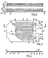
- Heat exchanger 10 includes a top or end plate 12, a turbulizer plate 14, core plates 16, 18, 20 and 22, another turbulizer plate 24 and a bottom or end plate 26. Plates 12 through 26 are shown arranged vertically in Figure 1, but this is only for the purposes of illustration. Heat exchanger 10 can have any orientation desired.
- Top end plate 12 is simply a flat plate formed of aluminum having a thickness of about 1 mm.
- Plate 12 has openings 28, 30 adjacent to one end thereof to form an inlet and an outlet for a first heat exchange fluid passing through heat exchanger 10.
- the bottom end plate 26 is also a flat aluminum plate, but plate 26 is thicker than plate 12 because it also acts as a mounting plate for heat exchanger 10.
- Extended corners 32 are provided in plate 26 and have openings 34 therein to accommodate suitable fasteners (are shown) for the mounting of heat exchanger 10 in a desired location.
- End plate 26 has a thickness typically of about 4 to 6 mm.
- End plate 26 also has openings 36, 38 to form respective inlet and outlet openings for a second heat exchange fluid for heat exchanger 10. Suitable inlet and outlet fittings or nipples (not shown) are attached to the plate inlets and outlets 36 and 38 (and also openings 28 and 30 in end plate 12) for the supply and return of the heat exchange fluids to heat exchanger 10.
- an optional controlled bypass groove 39 may be provided between openings 36, 38 to provide some deliberate bypass flow between the respective inlet and outlet formed by openings 36, 38.
- Turbulizer plate 14 is identical to turbulizer plate 24, but in Figure 1, turbulizer plate 24 has been turned end-for-end or 180° with respect to turbulizer plate 14, and turbulizer plate 24 has been turned upside down with respect to turbulizer plate 14. The following description of turbulizer plate 14, therefore, also applies to turbulizer plate 24.
- Turbulizer plate 14 may be referred to as a shim plate, and it has a central planar portion 40 and a peripheral edge portion 42. Undulating passageways 44 are formed in central planar portion 40 and are located on one side only of central planar portion 40, as seen best in Figure 4.
- This provides turbulizer plate 14 with a flat top surface 45 to engage the underside of end plate 12. Openings 46, 48 are located at the respective ends of undulating passages 44 to allow fluid to flow longitudinally through the undulating passageways 44 between top or end plate 12 and turbulizer 14. A central longitudinal rib 49, which appears as a groove 50 in Figure 3, is provided to engage the core plate 16 below it as seen in Figure 1. Turbulizer plate 14 is also provided with dimples 52, which also extend downwardly to engage core plate 16 below turbulizer 14. Openings 54 and 56 are also provided in turbulizer 14 to register with openings 28,30 in end plate 12 to allow fluid to flow transversely through turbulizer plate 14.
- Corner arcuate dimples 58 are also provided in turbulizer plate 14 to help locate turbulizer plate 14 in the assembly of heat exchanger 10. If desired, arcuate dimples 58 could be provided at all four corners of turbulizer plate 14, but only two are shown in Figures 1 to 3. These arcuate dimples also strengthen the corners of heat exchanger 10.
- heat exchanger 10 includes turbulizers 60 and 62 located between respective plates 16 and 18 and 18 and 20.
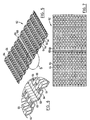
- Turbulizers 60 and 62 are formed of expanded metal, namely, aluminum, either by roll forming or a stamping operation. Staggered or offset transverse rows of convolutions 64 are provided in turbulizers 60, 62.
- the convolutions have flat tops 66 to provide good bonds with core plates 14, 16 and 18, although they could have round tops, or be in a sine wave configuration, if desired. Any type of turbulizer can be used in the present invention.
- transverse crimped portions 68 and 69 part of one of the transverse rows of convolutions 64 is compressed or roll formed or crimped together to form transverse crimped portions 68 and 69.
- crimped is intended to include crimping, stamping or roll forming, or any other method of closing up the convolutions in the turbulizers.
- Crimped portions 68, 69 reduces short-circuit flow inside the core plates, as will be discussed further below. It will be noted that only turbulizers 62 have crimped portions 68,. Turbulizers 60 do not have such crimped portions.
- turbulizers 60 are orientated so that the transverse rows of convolutions 64 are arranged transversely to the longitudinal direction of core plates 16 and 18. This is referred to as a high pressure drop arrangement.
- the transverse rows of convolutions 64 are located in the same direction as the longitudinal direction of core plates 18 and 20. This is referred to as the low pressure drop direction for turbulizer 62, because there is less flow resistance for fluid to flow through the convolutions in the same direction as row 64, as there is for the flow to try to flow through the row 64, as is the case with turbulizers 60.
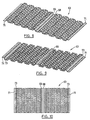
- a modified turbulizer 63 is shown where, in addition to crimped portions 68, 69, the distal ends or short edges 71, 73 are also crimped to help reduce short-circuit flow around the ends of the turbulizers, as will be described further below.
- Figure 11 is a plan view of core plates 16 and 20
- Figure 12 is a plan view of core plates 18 and 22.
- Figure 12 shows the back or underside of the plate of Figure 11.
- heat exchanger 10 is used to cool oil using coolant such as water
- Figure 11 would be referred to as the water side of the core plate
- Figure 12 would be referred to as the oil side of the core plate.
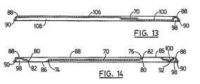
- Core plates 16 through 22 each have a planar central portion 70 and a first pair of spaced-apart bosses 72, 74 extending from one side of the planar central portion 70, namely the water side as seen in Figure 11.
- a second pair of spaced-apart bosses 76, 78 extends from the opposite side of planar central portion 70, namely the oil side as seen in Figure 12.
- the bosses 72 through 78 each have an inner peripheral edge portion 80, and an outer peripheral edge portion 82.
- the inner and outer peripheral edge portions 80, 82 define openings or fluid ports 84, 85, 86 and 87.
- a continuous peripheral ridge 88 (see Figure 12) encircles the inner peripheral edge portions 80 of at least the first pair of bosses 72, 74, but usually continuous ridge 88 encircles all four bosses 72,74, 76 and 78 as shown in Figure 12.
- Continuous ridge 88 extends from planar central portion 70 in the same direction and equidistantly with the outer peripheral edge portions 82 of the second pair of bosses 76, 78.
- Each of the core plate 16 to 22 also includes a raised peripheral flange 90 which extends from planar central portion 70 in the same direction and equidistantly with the outer peripheral edge portions 82 of the first pair of bosses 72, 74.
- core plates 16 and 18 are juxtaposed so that continuous ridges 88 are engaged to define a first fluid chamber between the respective plate planar central portions 70 bounded by the engaged continuous ridges 88.
- plates 16, 18 are positioned back-to-back with the oil sides of the respective plates facing each other for the flow of a first fluid, such as oil, between the plates.
- the outer peripheral edge portions 82 of the second pair of spaced-apart bosses 76,78 are engaged, with the respective fluid ports 85,84 and 84,85 in communication.
- core plates 18 and 20 are juxtaposed so that their respective peripheral flanges 90 are engaged also to define a first fluid chamber between the planar central portions of the plates and their respective engaged peripheral flanges 90.
- the outer peripheral edge portions 82 of the first pair of spaced-apart bosses 72,74 are engaged, with the respective fluid ports 87,86 and 86,87 being in communication.
- the third plate defines a second fluid chamber between the third plate and the adjacent plate pair.
- the fluid ports 84 and 85 or 86 and 87 become inlets and outlets for the flow of fluid in a U-shaped flow path inside the first and second fluid chambers.
- a T-shaped rib 92 is formed in the planar central portion 70.
- the height of rib 92 is equal to the height of peripheral flange 90.
- the head 94 of the T is located adjacent to the peripheral edge of the plate running behind bosses 76 and 78, and the stem 96 of the T extends longitudinally or inwardly between the second pair of spaced-apart bosses 76, 78.
- This T-shaped rib 92 engages the mating rib 92 on the adjacent plate and forms a barrier to prevent short-circuit flow between the inner peripheral edges 80 of the respective bosses 76 and 78.
- the continuous peripheral ridge 88 as seen in Figure 12 also produces a continuous peripheral groove 98 as seen in Figure 11.
- the T-shaped rib 92 prevents fluid from flowing from fluid ports 84 and 85 directly into the continuous groove 98 causing a short-circuit. It will be appreciated that the T-shaped rib 92 as seen in Figure 11 also forms a complimentary T-shaped groove 100 as seen in Figure 12.
- the T-shaped groove 100 is located between and around the outer peripheral edge portions 82 of bosses 76, 78, and this promotes the flow of fluid between and around the backside of these bosses, thus improving the heat exchange performance of heat exchanger 10.
- turbulizers 60 In Figure 12, the location of turbulizers 60 is indicated by chain dotted lines 102. In Figure 11, the chain dotted lines 104 represent turbulizer 62. Turbulizer 62 could be formed of two side-by-side turbulizer portions or segments, rather than the single turbulizer as indicated in Figures 1 and 5 to 7. In Figure 11, the turbulizer crimped portions 68 and 69 are indicated by the chain-dotted lines 105. These crimped portions 68 and 69 are located adjacent to the stem 96 of T-shaped rib 92 and also the inner edge portions 80 of bosses 76 and 78, to reduce short-circuit flow between bosses 76 and 78 around rib 96.
- the turbulizers 63 of Figure 8 to 10 could be used in heat exchanger 10.
- the crimped end portions 71, 73 would be a barrier and would block fluid flow from the turbulizer area to peripheral groove 98, again to reduce the bypass flow around peripheral groove 98.
- the crimped portions 68, 69 of turbulizer 62 and the crimped portions 71, 73 of turbulizer 63 are located in the flow paths inside the fluid chambers inside the plate pairs to prevent or reduce short-circuit flow from the inlets and outlets defined by fluid ports 84, 85 and 86, 87. It will be appreciated that the locations in the turbulizers of the crimped portions 68, 69 and 71, 73 can be varied to suit any particular heat exchanger configuration or to control the flow path inside the plate pairs.
- Core plates 16 to 22 also have another barrier located between the first pair of spaced-apart bosses 72 and 74.
- This barrier is formed by a rib 106 as seen in Figure 12 and a complimentary groove 108 as seen in Figure 11. Rib 106 prevents short-circuit flow between fluid ports 86 and 87 and again, the complimentary groove 108 on the water side of the core plates promotes flow between, around and behind the raised bosses 72 and 74 as seen in Figure 11. It will be appreciated that the height of rib 106 is equal to the height of continuous ridge 88 and also the outer peripheral edge portions 82 of bosses 76 and 78.
- the height of the T-shaped rib or barrier 92 is equal to the height of peripheral flange 90 and the outer peripheral edge portions 82 of bosses 72 and 74. Accordingly, when the respective plates are placed in juxtaposition, U-shaped flow passages or chambers are formed between the plates. On the water side of the core plates ( Figure 11), this U-shaped flow passage is bounded by T-shaped rib 92, crimped portions 68 and 69 of turbulizer 62, and peripheral flange 90. On the oil side of the core plates ( Figure 12), this U-shaped flow passage is bounded by rib 106 and continuous peripheral ridge 88.
- heat exchanger 10 is assembled by placing turbulizer plate 24 on top of end plate 26.
- the flat side of turbulizer plate 24 goes against end plate 26, and thus undulating passageways 44 extend above central planar portion 40 allowing fluid to flow on both sides of plate 24 through undulating passageways 44 only.
- Core plate 22 is placed overtop turbulizer plate 24.
- the water side ( Figure 11) of core plate 22 faces downwardly, so that bosses 72, 74 project downwardly as well, into engagement with the peripheral edges of openings 54 and 56.
- fluid flowing through openings 36 and 38 of end plate 26 pass through turbulizer openings 54, 56 and bosses 72, 74 to the upper or oil side of core plate 22.
- Fluid flowing through fluid ports 84 and 85 of core plate 22 would flow downwardly and through the undulating passageways 44 of turbulizer plate 24. This flow would be in a U-shaped direction, because rib 48 in turbulizer plate 24 covers or blocks longitudinal groove 108 in core plate 22, and also because the outer peripheral edge portions of bosses 72, 74 are sealed against the peripheral edges of turbulizer openings 54 and 56, so the flow has to go around or past bosses 72,74.
- Further core plates are stacked on top of core plate 22, first back-to-back as is the case with core plate 20 and then face-to-face as is the case with core plate 18 and so on. Only four core plates are shown in Figure 1, but of course, any number of core plates could be used in heat exchanger 10, as desired.
- fluid such as water
- entering opening 28 of end plate 12 would travel between turbulizer plate 14 and core plate 16 in a U-shaped fashion through the undulating passageways 44 of turbulizer plate 14, to pass up through opening 30 in end plate 12.
- Fluid flowing into opening 28 also passes downwardly through fluid ports 84 and 85 of respective core plates 16,18 to the U-shaped fluid chamber between core plates 18 and 20.
- the fluid then flows upwardly through fluid ports 84 and 85 of respective core plates 18 and 16, because the respective bosses defining ports 84 and 85 are engaged back-to-back. This upward flow then joins the fluid flowing through opening 56 to emerge from opening 30 in end plate 12.
- one fluid such as coolant or water
- passing through the openings 28 or 30 in end plate 12 travels through every other water side U-shaped flow passage or chamber between the stacked plates.
- the other fluid, such as oil, passing through openings 36 and 38 of end plate 26 flows through every other oil side U-shaped passage in the stacked plates that does not have the first fluid passing through it.
- FIG. 1 also illustrates that in addition to having the turbulizers 60 and 62 orientated differently, the turbulizers can be eliminated altogether, as indicated between core plates 20 and 22.
- Turbulizer plates 14 and 24 are actually shim plates. Turbulizer plates 14, 24 could be replaced with turbulizers 60 or 62, but the height or thickness of such turbulizers would have to be half that of turbulizers 60 and 62 because the spacing between the central planar portions 70 and the adjacent end plates 12 or 26 is half as high the spacing between central planar portions 70 of the juxtaposed core plates 16 to 22.
- planar central portions 70 are also formed with further barriers 110 having ribs 112 on the water side of planar central portions 70 and complimentary grooves 114 on the other or oil side of central planar portions 70.
- the ribs 112 help to reduce bypass flow by helping to prevent fluid from passing into the continuous peripheral grooves 98, and the grooves 114 promote flow on the oil side of the plates by encouraging the fluid to flow into the corners of the plates.
- Ribs 112 also perform a strengthening function by being joined to mating ribs on the adjacent or juxtaposed plate.
- Dimples 116 are also provided in planar central portions 70 to engage mating dimples on juxtaposed plates for strengthening purposes.
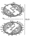
- FIG. 15 shows the plates 150, 152, 154 and 156 are circular and they are identical in plan view.
- Figure 15 shows the oil side of a pair of plates 150, 152 that have been unfolded along a chain-dotted fold line 158.
- Figure 16 shows the water side of a pair of plates 154, 156 that have been unfolded along a chain-dotted fold line 160.
- core plates 150 to 156 are quite similar to the core plates shown in Figures 1 to 14, so the same reference numerals are used in Figures 15 and 16 to indicate components or portions of the plates that are functionally the same as the embodiment of Figures 1 to 14.
- the bosses of the first pair of spaced-apart bosses 72, 74 are diametrically opposed and located adjacent to the continuous peripheral ridge 88.
- the bosses of the second pair of spaced-apart bosses 76, 78 are respectively located adjacent to the bosses 74, 72 of the first pair of spaced-apart bosses.
- Bosses 72 and 78 form a pair of associated input and output bosses, and the bosses 74 and 76 form a pair of associated input and output bosses.
- Oil side barriers in the form of ribs 158 and 160 reduce the likelihood of short circuit oil flow between fluid ports 86 and 87.
- ribs 158, 160 run tangentially from respective bosses 76, 78 into continuous ridge 88, and the heights of bosses 76, 78, ribs 158, 160 and continuous ridge 88 are all the same.
- the ribs or barriers 158, 160 are located between the respective pairs of associated input and output bosses 74, 76 and 72, 78.
- barriers or ribs 158, 160 can be considered to be spaced-apart barrier segments located adjacent to the respective associated input and output bosses.
- barrier ribs 158, 160 extend from the plate central planar portions in the same direction and equidistantly with the continuous ridge 88 and the outer peripheral edge portions 82 of the second pair of spaced-apart bosses 76, 78.
- a plurality of spaced-apart dimples 162 and 164 are formed in the plate planar central portions 70 and extend equidistantly with continuous ridge 88 on the oil side of the plates and raised peripheral flange 90 on the water side of the plates.
- the dimples 162, 164 are located to be in registration in juxtaposed first and second plates, and are thus joined together to strengthen the plate pairs, but dimples 162 also function to create flow augmentation between the plates on the oil side ( Figure 15) of the plate pairs. It will be noted that most of the dimples 162, 164 are located between the barrier segments or ribs 158, 160 and the continuous ridge 88.
- a turbulizer such as turbulizer 60 of the Figure 1 embodiment
- a turbulizer with crimped portions like the crimped end portions 71, 73 of turbulizers 63 could be used to help reduce bypass flow around the periphery of the plates.
- a barrier rib 168 is located in the centre of the plates and is of the same height as the first pair of spaced-apart bosses 72, 74. Barrier rib 168 reduces short circuit flow between fluid ports 84 and 85. The ribs 168 are also joined together in the mating plates to perform a strengthening function.
- a turbulizer like turbulizer 62 of Figure 1 could be used where the central crimped portions 68, 69 would take the place of barrier rib 168, the latter would then not be formed in plates 150, 152.
- Barrier ribs 158, 160 have complimentary grooves 170, 172 on the opposite or water sides of the plates, and these grooves 170, 172 promote flow to and from the peripheral edges of the plates to improve the flow distribution on the water side of the plates.
- central rib 168 has a complimentary groove 174 on the oil side of the plates to encourage fluid to flow toward the periphery of the plates.
- FIG. 17 to 20 yet another embodiment of a self-enclosing heat exchanger will now be described.
- a plurality of elongate flow directing ribs are formed in the plate planar central portions to prevent short-circuit flow between the respective ports in the pairs of spaced-apart bosses.
- the same reference numerals are used to indicate parts and components that are functionally equivalent to the embodiments described above.
- Figure 17 shows a core plate 212 that is similar to core plates 16, 20 of Figure 1
- Figure 18 shows a core plate 214 that is similar to core plates 18, 22 of Figure 1.
- the barrier rib between the second pair of spaced-apart bosses 76, 78 is more like a U-shaped rib 216 that encircles bosses 76, 78, but it does have a central portion or branch 218 that extends between the second pair of spaced-apart bosses 76, 78.
- the U-shaped portion of rib 216 has distal branches 220 and 222 that have respective spaced-apart rib segments 224, 226 and 228, 230 and 232.
- the distal branches 220 and 222 including their respective rib segments 224, 226 and 228, 230 and 232 extend along and adjacent to the continuous peripheral groove 98.
- Central branch or portion 218 includes a bifurcated extension formed of spaced-apart segments 234, 236, 238 and 240. It will be noted that all of the rib segments 224 through 240 are asymmetrically positioned or staggered in the plates, so that in juxtaposed plates having the respective raised peripheral flanges 90 engaged, the rib segments form half-height overlapping ribs to reduce bypass or short-circuit flow into the continuous peripheral groove 98 or the central longitudinal groove 108. It will also be noted that there is a space 241 between rib segment 234 and branch 218.
- This space 241 allows some flow therethrough to prevent stagnation which otherwise may occur at this location.
- the U-shaped rib 216 forms a complimentary groove 242 on the oil side of the plates as seen in Figure 18. This groove 242 promotes the flow of fluid between, around and behind bosses 76, 78 to improve the efficiency of the heat exchanger formed by plates 212, 214.
- the oil side of the plates can also be provided with turbulizers as indicated by chain-dotted lines 244, 246 in Figure 18.
- turbulizers preferably will be the same as turbulizers 60 in the embodiment of Figure 1.
- turbulizers like turbulizer 63 could also be used, in which case the crimped portions would run in the longitudinal direction of plates 212, 214.
- the crimped end portions 71, 73 of such turbulizers 63 could be crimped intermittently to produce the same result as rib segments 224 to 232, as could the central crimped portions 68, 69 to give the same effect as rib segments 234 to 240.
- the various rib segments would not be used.
- the terms oil side and water side have been used to describe the respective sides of the various core plates.
- the heat exchangers of the present invention are not limited to the use of fluids such as oil or water. Any fluids can be used in the heat exchangers of the present invention.
- the configuration or direction of flow inside the plate pairs can be chosen in any way desired simply by choosing which of the fluid flow ports 84 to 87 will be inlet or input ports and which will be outlet or output ports.
- the heat exchangers can be made in any shape desired.
- the heat exchangers have been described from the point of view of handling two heat transfer fluids, it will be appreciated that more than two fluids can be accommodated simply by nesting or expanding around the described structures using principles similar to those described above.
- some of the features of the individual embodiments described above can be mixed and matched and used in the other embodiments as will be appreciated by those skilled in the art.
Landscapes
- Engineering & Computer Science (AREA)
- Physics & Mathematics (AREA)
- Thermal Sciences (AREA)
- Mechanical Engineering (AREA)
- General Engineering & Computer Science (AREA)
- Heat-Exchange Devices With Radiators And Conduit Assemblies (AREA)
- Separation By Low-Temperature Treatments (AREA)
Abstract
Description
- This invention relates to a plate type heat exchanger of the type comprising the features of the preamble of claim 1.
Such a plate type heat exchanger is known from US-A-3 240 268, respectively US-A-4 327 802. - The most common kind of plate type heat exchangers produced in the past have been made of spaced-apart stacked pairs of plates where the plate pairs define internal flow passages therein. Expanded metal turbulizers are often located in the internal flow passages to increase turbulence and heat transfer efficiency. The plates normally have inlet and outlet openings that are aligned in the stacked plate pairs to allow for the flow of one heat exchange fluid through all of the plate pairs. A second heat exchange fluid passes between the plate pairs, and often an enclosure or casing is used to contain the plate pairs and cause the second heat exchange fluid to pass between the plate pairs.
- In order to eliminate the enclosure or casing, it has been proposed to provide the plates with peripheral flanges that not only close the peripheral edges of the plate pairs, but also close the peripheral spaces between the plate pairs. One method of doing this is to use plates that have a raised peripheral flange on one side of the plate and a raised peripheral ridge on the other side of the plate. Examples of this type of heat exchanger are shown in U.S. patent No. 3,240,268 issued to F.D. Armes and U.S. patent No. 4,327,802 issued to Richard P. Beldam.
- A difficulty with the self-enclosing plate-type heat exchangers produced in the past, however, is that the peripheral flanges and ridges form inherent peripheral flow channels that act as short-circuits inside and between the plate pairs, and this reduces the heat exchange efficiency of these types of heat exchangers.
- The present invention relates to improvements in plate type heat exchangers of the general type described, inter alia, in United States Patent No. 3,240,268 (Armes). Such prior art heat exchangers comprise first and second plates, each plate including a planar central portion, a first pair of spaced-apart bosses extending from one side of the planar central portion, and a second pair of spaced-apart bosses extending from the opposite side of the planar central portion. The bosses each have an inner peripheral edge portion and an outer peripheral edge portion defining a fluid port. A continuous ridge encircles the inner peripheral edge portions of at least the first pair of bosses and extends from the planar central portion in the same direction and equidistantly with the outer peripheral edge portions of the second pair of bosses. Each plate includes a raised peripheral flange extending from the planar central portion in the same direction and equidistantly with the outer peripheral edge portions of the first pair of bosses. The first and second plates are juxtaposed so that one of: the continuous ridges are engaged and the plate peripheral flanges are engaged; thereby defining a first flow chamber between the engaged ridges or peripheral flanges, with the fluid ports in one of said pairs of spaced-apart bosses forming an inlet and outlet to the first flow chamber, and the chamber defining a flow path between the inlet and outlet. The fluid ports in the respective first and second pairs of spaced-apart bosses are in registration. More particularly, the improvement relates to an expanded metal turbulizer, of the general type described, inter alia, in EP-A-0347961; DE-U-29622101 and WO-A-91/02208, which is conventionally located between the first and second plate planar central portions. The improvement as defined in claim 1 comprises a crimped portion of said turbulizer, whereat same has been crimped closed, said crimped portion being located in the flow path to reduce short-circuit flow between the inlet and the outlet, improve the flow distribution between the plates and improve the overall heat exchange efficiency of the heat exchanger.
- Preferred embodiments of the invention will now be described, by way of example, with reference to the accompanying drawings, in which:
- Figure 1 is an exploded perspective view of a first preferred embodiment of a self-enclosing heat exchanger made in accordance with the present invention;
- Figure 2 is an enlarged elevational view of the assembled heat exchanger of Figure 1;
- Figure 3 is a plan view of the top two plates shown in Figure 1, the top plate being broken away to show the plate beneath it;
- Figure 4 is a vertical sectional view taken along lines 4-4 of Figure 3, but showing both plates of Figure 3;
- Figure 5 is an enlarged perspective view taken along lines 5-5 of Figure 1 showing one of the turbulizers used in the embodiment shown in Figure 1;
- Figure 6 is an enlarged scrap view of the portion of Figure 5 indicated by circle 6 in Figure 5;
- Figure 7 is a plan view of the turbulizer shown in Figure 5;
- Figure 8 is a perspective view similar to Figure 5, but showing another embodiment of a turbulizer for use in the present invention;
- Figure 9 is a perspective view of the turbulizer of Figure 8 but rotated 180 degrees about the longitudinal axis of the turbulizer;
- Figure 10 is a plan view of the turbulizer as shown in Figure 8;
- Figure 11 is a plan view of one side of one of the core plates used in the heat exchanger of Figure 1;
- Figure 12 is a plan view of the opposite side of the core plate shown in Figure 11;
- Figure 13 is a vertical sectional view taken along lines 13-13 of Figure 12;
- Figure 14 is a vertical sectional view taken along lines 14-14 of Figure 12;
- Figure 15 is a perspective view of the unfolded plates of a plate pair used to make yet another preferred embodiment of a heat exchanger according to the present invention;
- Figure 16 is a perspective view similar to Figure 15, but showing the unfolded plates where they would be folded together face-to-face;
- Figure 17 is a plan view of yet another preferred embodiment of a plate used to make a self-enclosing heat exchanger according to the present invention;
- Figure 18 is a plan view of the opposite side of the plate shown in Figure 17;
- Figure 19 is a vertical sectional view in along lines 19-19 of Figure 17, but showing the assembled plates of Figures 17 and 18; and
- Figure 20 is a vertical elevational view of the assembled plates of Figures 17 to 19.
-
- Referring firstly to Figures 1 and 2, an exploded perspective view of a preferred embodiment of a heat exchanger according to the present invention is generally indicated by
reference numeral 10.Heat exchanger 10 includes a top orend plate 12, aturbulizer plate 14,core plates turbulizer plate 24 and a bottom orend plate 26.Plates 12 through 26 are shown arranged vertically in Figure 1, but this is only for the purposes of illustration.Heat exchanger 10 can have any orientation desired. -
Top end plate 12 is simply a flat plate formed of aluminum having a thickness of about 1 mm.Plate 12 hasopenings heat exchanger 10. Thebottom end plate 26 is also a flat aluminum plate, butplate 26 is thicker thanplate 12 because it also acts as a mounting plate forheat exchanger 10.Extended corners 32 are provided inplate 26 and haveopenings 34 therein to accommodate suitable fasteners (are shown) for the mounting ofheat exchanger 10 in a desired location.End plate 26 has a thickness typically of about 4 to 6 mm.End plate 26 also hasopenings heat exchanger 10. Suitable inlet and outlet fittings or nipples (not shown) are attached to the plate inlets andoutlets 36 and 38 (and also openings 28 and 30 in end plate 12) for the supply and return of the heat exchange fluids toheat exchanger 10. - Although it is normally not desirable to have short-circuit or bypass flow inside the heat exchanger core plates, in some applications, it is desirable to have some bypass flow in the flow circuit that includes
heat exchanger 10. This bypass, for example, could be needed to reduce the pressure drop inheat exchanger 10, or to provide some cold flow bypass between the supply and return lines toheat exchanger 10. For this purpose, an optional controlledbypass groove 39 may be provided betweenopenings openings - Referring next to Figures 1, 3 and 4,
turbulizer plates Turbulizer plate 14 is identical toturbulizer plate 24, but in Figure 1,turbulizer plate 24 has been turned end-for-end or 180° with respect toturbulizer plate 14, andturbulizer plate 24 has been turned upside down with respect toturbulizer plate 14. The following description ofturbulizer plate 14, therefore, also applies toturbulizer plate 24.Turbulizer plate 14 may be referred to as a shim plate, and it has a centralplanar portion 40 and aperipheral edge portion 42. Undulatingpassageways 44 are formed in centralplanar portion 40 and are located on one side only of centralplanar portion 40, as seen best in Figure 4. This providesturbulizer plate 14 with a flattop surface 45 to engage the underside ofend plate 12.Openings passages 44 to allow fluid to flow longitudinally through the undulatingpassageways 44 between top orend plate 12 andturbulizer 14. A centrallongitudinal rib 49, which appears as agroove 50 in Figure 3, is provided to engage thecore plate 16 below it as seen in Figure 1.Turbulizer plate 14 is also provided withdimples 52, which also extend downwardly to engagecore plate 16 belowturbulizer 14.Openings turbulizer 14 to register withopenings end plate 12 to allow fluid to flow transversely throughturbulizer plate 14. Cornerarcuate dimples 58 are also provided inturbulizer plate 14 to help locateturbulizer plate 14 in the assembly ofheat exchanger 10. If desired,arcuate dimples 58 could be provided at all four corners ofturbulizer plate 14, but only two are shown in Figures 1 to 3. These arcuate dimples also strengthen the corners ofheat exchanger 10. - Referring next to Figures 1 and 5 to 7,
heat exchanger 10 includesturbulizers respective plates convolutions 64 are provided inturbulizers flat tops 66 to provide good bonds withcore plates convolutions 64 is compressed or roll formed or crimped together to form transversecrimped portions Crimped portions portions 68,.Turbulizers 60 do not have such crimped portions. - As seen best in Figure 1, turbulizers 60 are orientated so that the transverse rows of
convolutions 64 are arranged transversely to the longitudinal direction ofcore plates turbulizer 62, the transverse rows ofconvolutions 64 are located in the same direction as the longitudinal direction ofcore plates turbulizer 62, because there is less flow resistance for fluid to flow through the convolutions in the same direction asrow 64, as there is for the flow to try to flow through therow 64, as is the case withturbulizers 60. - Referring next to Figures 8 to 10, a modified
turbulizer 63 is shown where, in addition to crimpedportions short edges - Referring next to Figures 1 and 11 to 14,
core plates heat exchanger 10, alternating core plates are turned upside down. Figure 11 is a plan view ofcore plates core plates heat exchanger 10 is used to cool oil using coolant such as water, for example, Figure 11 would be referred to as the water side of the core plate and Figure 12 would be referred to as the oil side of the core plate. -
Core plates 16 through 22 each have a planarcentral portion 70 and a first pair of spaced-apart bosses central portion 70, namely the water side as seen in Figure 11. A second pair of spaced-apart bosses central portion 70, namely the oil side as seen in Figure 12. Thebosses 72 through 78 each have an innerperipheral edge portion 80, and an outerperipheral edge portion 82. The inner and outerperipheral edge portions fluid ports peripheral edge portions 80 of at least the first pair ofbosses continuous ridge 88 encircles all fourbosses Continuous ridge 88 extends from planarcentral portion 70 in the same direction and equidistantly with the outerperipheral edge portions 82 of the second pair ofbosses - Each of the
core plate 16 to 22 also includes a raisedperipheral flange 90 which extends from planarcentral portion 70 in the same direction and equidistantly with the outerperipheral edge portions 82 of the first pair ofbosses - As seen in Figure 1,
core plates continuous ridges 88 are engaged to define a first fluid chamber between the respective plate planarcentral portions 70 bounded by the engagedcontinuous ridges 88. In other words,plates peripheral edge portions 82 of the second pair of spaced-apart bosses respective fluid ports core plates peripheral flanges 90 are engaged also to define a first fluid chamber between the planar central portions of the plates and their respective engagedperipheral flanges 90. In this configuration, the outerperipheral edge portions 82 of the first pair of spaced-apart bosses respective fluid ports fluid ports - Referring in particular to Figure 11, a T-shaped
rib 92 is formed in the planarcentral portion 70. The height ofrib 92 is equal to the height ofperipheral flange 90. Thehead 94 of the T is located adjacent to the peripheral edge of the plate running behindbosses stem 96 of the T extends longitudinally or inwardly between the second pair of spaced-apart bosses rib 92 engages themating rib 92 on the adjacent plate and forms a barrier to prevent short-circuit flow between the innerperipheral edges 80 of therespective bosses peripheral ridge 88 as seen in Figure 12 also produces a continuousperipheral groove 98 as seen in Figure 11. The T-shapedrib 92 prevents fluid from flowing fromfluid ports continuous groove 98 causing a short-circuit. It will be appreciated that the T-shapedrib 92 as seen in Figure 11 also forms a complimentary T-shapedgroove 100 as seen in Figure 12. The T-shapedgroove 100 is located between and around the outerperipheral edge portions 82 ofbosses heat exchanger 10. - In Figure 12, the location of turbulizers 60 is indicated by chain dotted
lines 102. In Figure 11, the chain dottedlines 104 representturbulizer 62.Turbulizer 62 could be formed of two side-by-side turbulizer portions or segments, rather than the single turbulizer as indicated in Figures 1 and 5 to 7. In Figure 11, the turbulizer crimpedportions lines 105. Thesecrimped portions stem 96 of T-shapedrib 92 and also theinner edge portions 80 ofbosses bosses rib 96. - Instead of using
turbulizers 62 as indicated in Figures 1 and 11, theturbulizers 63 of Figure 8 to 10 could be used inheat exchanger 10. In this case, thecrimped end portions peripheral groove 98, again to reduce the bypass flow aroundperipheral groove 98. Thecrimped portions turbulizer 62 and thecrimped portions turbulizer 63 are located in the flow paths inside the fluid chambers inside the plate pairs to prevent or reduce short-circuit flow from the inlets and outlets defined byfluid ports portions -
Core plates 16 to 22 also have another barrier located between the first pair of spaced-apart bosses rib 106 as seen in Figure 12 and acomplimentary groove 108 as seen in Figure 11.Rib 106 prevents short-circuit flow betweenfluid ports complimentary groove 108 on the water side of the core plates promotes flow between, around and behind the raisedbosses rib 106 is equal to the height ofcontinuous ridge 88 and also the outerperipheral edge portions 82 ofbosses barrier 92 is equal to the height ofperipheral flange 90 and the outerperipheral edge portions 82 ofbosses rib 92, crimpedportions turbulizer 62, andperipheral flange 90. On the oil side of the core plates (Figure 12), this U-shaped flow passage is bounded byrib 106 and continuousperipheral ridge 88. - Referring once again to Figure 1,
heat exchanger 10 is assembled by placingturbulizer plate 24 on top ofend plate 26. The flat side ofturbulizer plate 24 goes againstend plate 26, and thus undulatingpassageways 44 extend above centralplanar portion 40 allowing fluid to flow on both sides ofplate 24 through undulatingpassageways 44 only.Core plate 22 is placed overtopturbulizer plate 24. As seen in Figure 1, the water side (Figure 11) ofcore plate 22 faces downwardly, so thatbosses openings openings end plate 26 pass throughturbulizer openings bosses core plate 22. Fluid flowing throughfluid ports core plate 22 would flow downwardly and through the undulatingpassageways 44 ofturbulizer plate 24. This flow would be in a U-shaped direction, becauserib 48 inturbulizer plate 24 covers or blockslongitudinal groove 108 incore plate 22, and also because the outer peripheral edge portions ofbosses turbulizer openings past bosses core plate 22, first back-to-back as is the case withcore plate 20 and then face-to-face as is the case withcore plate 18 and so on. Only four core plates are shown in Figure 1, but of course, any number of core plates could be used inheat exchanger 10, as desired. - At the top of
heat exchanger 10, the flat side ofturbulizer plate 14 bears against the underside ofend plate 12. The water side ofcore plate 16 bears againstturbulizer plate 14. Theperipheral edge portion 42 ofturbulizer plate 14 is coterminous withperipheral flange 90 ofcore plate 14 and the peripheral edges ofend plate 12, so fluid flowing throughopenings openings turbulizer plate 14 to the water side ofcore plate 16.Rib 48 ofturbulizer plate 14 covers or blocks groove 108 incore plate 14. From this, it will be apparent that fluid, such as water, enteringopening 28 ofend plate 12 would travel betweenturbulizer plate 14 andcore plate 16 in a U-shaped fashion through the undulatingpassageways 44 ofturbulizer plate 14, to pass up through opening 30 inend plate 12. Fluid flowing into opening 28 also passes downwardly throughfluid ports respective core plates core plates fluid ports respective core plates bosses defining ports end plate 12. From this it will be seen that one fluid, such as coolant or water, passing through theopenings end plate 12 travels through every other water side U-shaped flow passage or chamber between the stacked plates. The other fluid, such as oil, passing throughopenings end plate 26 flows through every other oil side U-shaped passage in the stacked plates that does not have the first fluid passing through it. - Figure 1 also illustrates that in addition to having the
turbulizers core plates Turbulizer plates Turbulizer plates turbulizers turbulizers planar portions 70 and theadjacent end plates planar portions 70 of the juxtaposedcore plates 16 to 22. - Referring again to Figures 11and 12, planar
central portions 70 are also formed withfurther barriers 110 havingribs 112 on the water side of planarcentral portions 70 andcomplimentary grooves 114 on the other or oil side of centralplanar portions 70. Theribs 112 help to reduce bypass flow by helping to prevent fluid from passing into the continuousperipheral grooves 98, and thegrooves 114 promote flow on the oil side of the plates by encouraging the fluid to flow into the corners of the plates.Ribs 112 also perform a strengthening function by being joined to mating ribs on the adjacent or juxtaposed plate.Dimples 116 are also provided in planarcentral portions 70 to engage mating dimples on juxtaposed plates for strengthening purposes. - Referring next to Figures 15 and 16, some further plates are shown for producing yet another preferred embodiment of a self-enclosing heat exchanger according to the present invention. In this embodiment, the
plates plates fold line 158. Figure 16 shows the water side of a pair ofplates fold line 160. Again,core plates 150 to 156 are quite similar to the core plates shown in Figures 1 to 14, so the same reference numerals are used in Figures 15 and 16 to indicate components or portions of the plates that are functionally the same as the embodiment of Figures 1 to 14. - In the embodiment of Figures 15 and 16, the bosses of the first pair of spaced-
apart bosses peripheral ridge 88. The bosses of the second pair of spaced-apart bosses bosses Bosses bosses ribs fluid ports ribs respective bosses continuous ridge 88, and the heights ofbosses ribs continuous ridge 88 are all the same. The ribs orbarriers output bosses ribs barrier ribs continuous ridge 88 and the outerperipheral edge portions 82 of the second pair of spaced-apart bosses - A plurality of spaced-apart
dimples central portions 70 and extend equidistantly withcontinuous ridge 88 on the oil side of the plates and raisedperipheral flange 90 on the water side of the plates. Thedimples dimples ribs continuous ridge 88. This permits a turbulizer, such asturbulizer 60 of the Figure 1 embodiment, to inserted between the plates as indicated by the chain-dottedline 166 in Figure 15. Also, a turbulizer with crimped portions, like thecrimped end portions turbulizers 63 could be used to help reduce bypass flow around the periphery of the plates. - On the water side of
plates barrier rib 168 is located in the centre of the plates and is of the same height as the first pair of spaced-apart bosses Barrier rib 168 reduces short circuit flow betweenfluid ports ribs 168 are also joined together in the mating plates to perform a strengthening function. Alternatively, a turbulizer liketurbulizer 62 of Figure 1 could be used where the central crimpedportions barrier rib 168, the latter would then not be formed inplates -
Barrier ribs complimentary grooves grooves central rib 168 has acomplimentary groove 174 on the oil side of the plates to encourage fluid to flow toward the periphery of the plates. - Referring next to Figures 17 to 20, yet another embodiment of a self-enclosing heat exchanger will now be described. In this embodiment, a plurality of elongate flow directing ribs are formed in the plate planar central portions to prevent short-circuit flow between the respective ports in the pairs of spaced-apart bosses. In Figures 17 to 20, the same reference numerals are used to indicate parts and components that are functionally equivalent to the embodiments described above.
- Figure 17 shows a
core plate 212 that is similar tocore plates core plate 214 that is similar tocore plates core plate 212, the barrier rib between the second pair of spaced-apart bosses U-shaped rib 216 that encirclesbosses branch 218 that extends between the second pair of spaced-apart bosses rib 216 hasdistal branches rib segments distal branches respective rib segments peripheral groove 98. Central branch orportion 218 includes a bifurcated extension formed of spaced-apartsegments rib segments 224 through 240 are asymmetrically positioned or staggered in the plates, so that in juxtaposed plates having the respective raisedperipheral flanges 90 engaged, the rib segments form half-height overlapping ribs to reduce bypass or short-circuit flow into the continuousperipheral groove 98 or the centrallongitudinal groove 108. It will also be noted that there is aspace 241 betweenrib segment 234 andbranch 218. Thisspace 241 allows some flow therethrough to prevent stagnation which otherwise may occur at this location. As in the case of the previously embodiments, theU-shaped rib 216 forms acomplimentary groove 242 on the oil side of the plates as seen in Figure 18. Thisgroove 242 promotes the flow of fluid between, around and behindbosses plates - The oil side of the plates can also be provided with turbulizers as indicated by chain-dotted
lines 244, 246 in Figure 18. These turbulizers preferably will be the same asturbulizers 60 in the embodiment of Figure 1. However, turbulizers liketurbulizer 63 could also be used, in which case the crimped portions would run in the longitudinal direction ofplates crimped end portions such turbulizers 63 could be crimped intermittently to produce the same result asrib segments 224 to 232, as could the central crimpedportions rib segments 234 to 240. Of course, where crimped turbulizers are used, the various rib segments would not be used. - It is also possible to make the bifurcated extension of
central branch 218 so that the forks consisting ofrespective rib segments - In the above description, for the purposes of clarification, the terms oil side and water side have been used to describe the respective sides of the various core plates. It will be understood that the heat exchangers of the present invention are not limited to the use of fluids such as oil or water. Any fluids can be used in the heat exchangers of the present invention. Also, the configuration or direction of flow inside the plate pairs can be chosen in any way desired simply by choosing which of the
fluid flow ports 84 to 87 will be inlet or input ports and which will be outlet or output ports. - Having described preferred embodiments of the invention, it will be appreciated that various modifications may be made to the structures described above. For example, the heat exchangers can be made in any shape desired. Although the heat exchangers have been described from the point of view of handling two heat transfer fluids, it will be appreciated that more than two fluids can be accommodated simply by nesting or expanding around the described structures using principles similar to those described above. Further, some of the features of the individual embodiments described above can be mixed and matched and used in the other embodiments as will be appreciated by those skilled in the art.
Claims (7)
- A plate type heat exchanger (10) of the type comprising:characterised in thatfirst (18) and second (20) plates, each plate (18,20) including a planar central portion (70), a first pair of spaced-apart bosses (72,74) extending from one side of the planar central portion (70), and a second pair of spaced-apart bosses (76,78) extending from the opposite side of the planar central portion (70), said bosses (72,74,76,78) each having an inner peripheral edge portion (80), and an outer peripheral edge portion (82) defining a fluid port (87,86,85,84); a continuous ridge (88) encircling the inner peripheral edge portions (80) of at least the first pair of bosses (72,74) and extending from the planar central portion (70) in the same direction and equidistantly with the outer peripheral edge portions (82) of the second pair of bosses (76,78);each plate (18,20) including a raised peripheral flange (90) extending from the planar central portion (70) in the same direction and equidistantly with the outer peripheral edge portions (82) of the first pair of bosses (72,74);the first (18) and second (20) plates being juxtaposed so that one of: the continuous ridges (88) are engaged or the plate peripheral flanges (90) are engaged; thereby defining a first fluid chamber between the engaged ridges (88) or peripheral flanges (90), with the fluid ports (87,86,85,84) in one of said pairs of spaced-apart bosses forming an inlet and an outlet to said first flow chamber, and said chamber defining a flow path between said inlet and outlet; the fluid ports (87,86,85,84) in the respective first (72,74) and second (76,78) pairs of spaced-apart bosses being in registration; andan expanded metal turbulizer (62) located between the first (18) and second (20) plate planar central portions (70),
the turbulizer (62) includes a crimped portion (68,69) whereat the expanded metal turbulizer has been crimped closed, said crimped portion being located in said flow path to reduce short-circuit flow between said inlet and outlet. - A plate type heat exchanger (10) as claimed in claim 1 wherein the continuous ridge (88) encircles both the first (72,74) and second (76,78) pairs of spaced-apart bosses and further comprising a third plate (16) located in juxtaposition with one of the first (18) and second (20) plates to define a second fluid chamber between the third plate (16) and the central planar portion (70) of the adjacent plate.
- A plate type heat exchanger (10) as claimed in claim 2 wherein the first (18) and second (20) plate peripheral flanges (90,90) are engaged and wherein the turbulizer (62)is located in the first fluid chamber defined thereby.
- A plate type heat exchanger (10) as claimed in claim 2 wherein the plates (150,152,154,156) are circular in plan view, the bosses of the first pair of spaced-apart bosses (72,74) are diametrically opposed and located adjacent to the continuous ridge (88), the bosses of the second pair of spaced-apart bosses (76,78) are respectively located adjacent to the bosses of the first pair of spaced-apart bosses (72,74) to form pairs of associated input and output bosses, and the turbulizer (63) is located between the respective pairs of associated input and output bosses.
- A plate type heat exchanger (10) as claimed in claim 2 and further comprising a turbulizer (60) located inside the second fluid chamber.
- A plate type heat exchanger (10) as claimed in claim 3 wherein the planar central portion (70) includes a barrier formed of a rib (92) and complimentary groove (100), the rib (92) being located between the inner peripheral edge portions (80) of the bosses of the second pair of spaced-apart bosses (76,78), the groove (100) being located in the first fluid chamber, and the turbulizer crimped portion (68) being located over the groove (100) to reduce short-circuit flow through the groove (100).
- A plate type heat exchanger (10) as claimed in claim 1 wherein the continuous ridge (88) encircles both the first (72,74) and second (76,78) pairs of spaced-apart bosses, said continuous ridge (88) forming a complimentary continuous peripheral groove (98) around the plate (16,18,20) adjacent to the raised peripheral flange (90), the turbulizer (63) having crimped end portions (71,73) located adjacent to the continuous peripheral groove (98) to reduce short-circuit flow therethrough.
Applications Claiming Priority (3)
| Application Number | Priority Date | Filing Date | Title |
|---|---|---|---|
| CA2260890 | 1999-02-05 | ||
| CA002260890A CA2260890A1 (en) | 1999-02-05 | 1999-02-05 | Self-enclosing heat exchangers |
| PCT/CA2000/000112 WO2000046563A1 (en) | 1999-02-05 | 2000-02-04 | Self-enclosing heat exchanger with crimped turbulizer |
Publications (2)
| Publication Number | Publication Date |
|---|---|
| EP1149266A1 EP1149266A1 (en) | 2001-10-31 |
| EP1149266B1 true EP1149266B1 (en) | 2004-10-06 |
Family
ID=4163258
Family Applications (3)
| Application Number | Title | Priority Date | Filing Date |
|---|---|---|---|
| EP00903448A Expired - Lifetime EP1149264B1 (en) | 1999-02-05 | 2000-02-04 | Self-enclosing heat exchangers with shim plate |
| EP00904749A Expired - Lifetime EP1149266B1 (en) | 1999-02-05 | 2000-02-04 | Self-enclosing heat exchanger with crimped turbulizer |
| EP00903449A Expired - Lifetime EP1149265B1 (en) | 1999-02-05 | 2000-02-04 | Self-enclosing heat exchangers |
Family Applications Before (1)
| Application Number | Title | Priority Date | Filing Date |
|---|---|---|---|
| EP00903448A Expired - Lifetime EP1149264B1 (en) | 1999-02-05 | 2000-02-04 | Self-enclosing heat exchangers with shim plate |
Family Applications After (1)
| Application Number | Title | Priority Date | Filing Date |
|---|---|---|---|
| EP00903449A Expired - Lifetime EP1149265B1 (en) | 1999-02-05 | 2000-02-04 | Self-enclosing heat exchangers |
Country Status (11)
| Country | Link |
|---|---|
| US (4) | US6340053B1 (en) |
| EP (3) | EP1149264B1 (en) |
| JP (3) | JP3524064B2 (en) |
| KR (1) | KR100407767B1 (en) |
| AT (3) | ATE265665T1 (en) |
| AU (3) | AU748688B2 (en) |
| BR (1) | BR0008007B1 (en) |
| CA (1) | CA2260890A1 (en) |
| DE (3) | DE60010226T2 (en) |
| ES (2) | ES2219304T3 (en) |
| WO (3) | WO2000046564A1 (en) |
Families Citing this family (147)
| Publication number | Priority date | Publication date | Assignee | Title |
|---|---|---|---|---|
| DK0989937T3 (en) * | 1997-06-24 | 2004-12-06 | Micro Heat Inc | Windscreen defrost |
| US6669109B2 (en) * | 1998-11-06 | 2003-12-30 | Micro-Heat Inc | Apparatus for cleaning or de-icing a vehicle window |
| CA2257076C (en) * | 1998-12-23 | 2005-03-22 | Long Manufacturing Ltd. | Radial flow annular heat exchangers |
| WO2002035666A1 (en) * | 2000-10-20 | 2002-05-02 | Mitsubishi Denki Kabushiki Kaisha | Cooler, semiconductor laser light source, semiconductor laser light source unit, method for producing semiconductor laser light source unit, and solid laser |
| US7011142B2 (en) * | 2000-12-21 | 2006-03-14 | Dana Canada Corporation | Finned plate heat exchanger |
| JP2003008273A (en) * | 2001-06-25 | 2003-01-10 | Fanuc Ltd | Cooler and light source apparatus |
| SE519570C2 (en) * | 2001-07-09 | 2003-03-11 | Alfa Laval Corp Ab | Heat transfer plate with flow separator; plate packages and plate heat exchangers |
| FI113695B (en) * | 2001-10-09 | 2004-05-31 | Vahterus Oy | Welded heat exchanger with disc construction |
| US7328886B2 (en) * | 2001-10-11 | 2008-02-12 | Spx Cooling Technologies, Inc. | Air-to-air atmospheric heat exchanger for condensing cooling tower effluent |
| DE10152363A1 (en) * | 2001-10-24 | 2003-05-08 | Modine Mfg Co | Caseless plate heat exchanger |
| FI118391B (en) * | 2001-12-27 | 2007-10-31 | Vahterus Oy | Device for improving heat transfer in round plate heat exchangers |
| CA2372399C (en) * | 2002-02-19 | 2010-10-26 | Long Manufacturing Ltd. | Low profile finned heat exchanger |
| US6560934B1 (en) * | 2002-04-15 | 2003-05-13 | Deslauriers, Inc. | Snappable shim assembly |
| US20040173341A1 (en) * | 2002-04-25 | 2004-09-09 | George Moser | Oil cooler and production method |
| CA2384712A1 (en) * | 2002-05-03 | 2003-11-03 | Michel St. Pierre | Heat exchanger with nest flange-formed passageway |
| US6953009B2 (en) * | 2002-05-14 | 2005-10-11 | Modine Manufacturing Company | Method and apparatus for vaporizing fuel for a reformer fuel cell system |
| US20040003916A1 (en) * | 2002-07-03 | 2004-01-08 | Ingersoll-Rand Energy Systems, Inc. | Unit cell U-plate-fin crossflow heat exchanger |
| CA2392610C (en) * | 2002-07-05 | 2010-11-02 | Long Manufacturing Ltd. | Baffled surface cooled heat exchanger |
| US7011904B2 (en) * | 2002-07-30 | 2006-03-14 | General Electric Company | Fluid passages for power generation equipment |
| US7219720B2 (en) * | 2002-10-11 | 2007-05-22 | Showa Denko K.K. | Flat hollow body for passing fluid therethrough, heat exchanger comprising the hollow body and process for fabricating the heat exchanger |
| EP1411311A1 (en) * | 2002-10-17 | 2004-04-21 | Jean Luc Deloy | Heating device comprising a heat exchanger system |
| CN100480110C (en) * | 2002-10-21 | 2009-04-22 | 微热公司 | Apparatus and method for cleaning or de-icing a vehicle element |
| EP1556262A2 (en) * | 2002-10-21 | 2005-07-27 | Microheat Inc. | Apparatus and method for cleaning or de-icing vehicle elements |
| FR2846733B1 (en) * | 2002-10-31 | 2006-09-15 | Valeo Thermique Moteur Sa | CONDENSER, IN PARTICULAR FOR A CIRCUIT FOR CIMATING A MOTOR VEHICLE, AND CIRCUIT COMPRISING THE CONDENSER |
| US7069981B2 (en) * | 2002-11-08 | 2006-07-04 | Modine Manufacturing Company | Heat exchanger |
| US20040099408A1 (en) * | 2002-11-26 | 2004-05-27 | Shabtay Yoram Leon | Interconnected microchannel tube |
| WO2004051171A2 (en) * | 2002-12-02 | 2004-06-17 | Lg Electronics Inc. | Heat exchanger of ventilating system |
| DE10304692A1 (en) * | 2003-02-06 | 2004-08-19 | Modine Manufacturing Co., Racine | Corrugated insert for a heat exchanger tube |
| CA2425233C (en) * | 2003-04-11 | 2011-11-15 | Dana Canada Corporation | Surface cooled finned plate heat exchanger |
| ES2234414B1 (en) * | 2003-09-24 | 2006-11-01 | Valeo Termico, S.A. | HEAT EXCHANGER OF STACKED PLATES. |
| DE10349141A1 (en) * | 2003-10-17 | 2005-05-12 | Behr Gmbh & Co Kg | Stacked plate heat exchangers, in particular oil coolers for motor vehicles |
| DE10352880A1 (en) * | 2003-11-10 | 2005-06-09 | Behr Gmbh & Co. Kg | Heat exchanger, in particular charge air / coolant radiator |
| DE10352881A1 (en) | 2003-11-10 | 2005-06-09 | Behr Gmbh & Co. Kg | Heat exchanger, in particular charge air / coolant radiator |
| US7191824B2 (en) * | 2003-11-21 | 2007-03-20 | Dana Canada Corporation | Tubular charge air cooler |
| CA2451424A1 (en) * | 2003-11-28 | 2005-05-28 | Dana Canada Corporation | Low profile heat exchanger with notched turbulizer |
| CA2451428C (en) * | 2003-11-28 | 2011-10-25 | Dana Canada Corporation | Brazed sheets with aligned openings and heat exchanger formed therefrom |
| SE0303307L (en) * | 2003-12-10 | 2004-10-19 | Swep Int Ab | Plate heat exchanger |
| DE102004004975B4 (en) * | 2004-01-31 | 2015-04-23 | Modine Manufacturing Co. | Plate heat exchangers |
| EP1750982B1 (en) | 2004-02-12 | 2012-11-28 | M-Heat Investors, LLC | Apparatus and method for cleaning and de-icing |
| CA2466688A1 (en) * | 2004-04-30 | 2005-10-30 | Dana Canada Corporation | Apparatus and method for forming shaped articles |
| WO2006013075A1 (en) * | 2004-07-30 | 2006-02-09 | Behr Gmbh & Co. Kg | One-piece turbulence insert |
| US7178581B2 (en) * | 2004-10-19 | 2007-02-20 | Dana Canada Corporation | Plate-type heat exchanger |
| JP4675620B2 (en) * | 2004-12-27 | 2011-04-27 | 株式会社マーレ フィルターシステムズ | Oil cooler |
| ES2257209B1 (en) * | 2005-01-13 | 2008-06-16 | Valeo Termico, S.A. | HEAT EXCHANGER OF STACKED PLATES. |
| US20080184732A1 (en) * | 2005-01-14 | 2008-08-07 | Jens Hadler | Evaporator, in Particular for an Air-Conditioning System of a Motor Vehicle |
| JP2006284165A (en) * | 2005-03-07 | 2006-10-19 | Denso Corp | Exhaust gas heat exchanger |
| US20060254162A1 (en) * | 2005-04-21 | 2006-11-16 | Deslauriers, Inc. | Shim having through openings |
| DE102005034305A1 (en) * | 2005-07-22 | 2007-01-25 | Behr Gmbh & Co. Kg | Plate element for a plate cooler |
| US7264045B2 (en) * | 2005-08-23 | 2007-09-04 | Delphi Technologies, Inc. | Plate-type evaporator to suppress noise and maintain thermal performance |
| DE102005044291A1 (en) | 2005-09-16 | 2007-03-29 | Behr Industry Gmbh & Co. Kg | Stacking plate heat exchanger, in particular intercooler |
| SE531472C2 (en) | 2005-12-22 | 2009-04-14 | Alfa Laval Corp Ab | Heat exchanger with heat transfer plate with even load distribution at contact points at port areas |
| US20070235174A1 (en) * | 2005-12-23 | 2007-10-11 | Dakhoul Youssef M | Heat exchanger |
| US7377308B2 (en) * | 2006-05-09 | 2008-05-27 | Modine Manufacturing Company | Dual two pass stacked plate heat exchanger |
| JP5059858B2 (en) | 2006-07-24 | 2012-10-31 | エム−ヒート インベスターズ,リミティド ライアビリティ カンパニー | Vehicle surface cleaning and deicing systems and methods |
| US20080041556A1 (en) * | 2006-08-18 | 2008-02-21 | Modine Manufacutring Company | Stacked/bar plate charge air cooler including inlet and outlet tanks |
| US8985198B2 (en) * | 2006-08-18 | 2015-03-24 | Modine Manufacturing Company | Stacked/bar plate charge air cooler including inlet and outlet tanks |
| GB0617721D0 (en) * | 2006-09-08 | 2006-10-18 | Univ Warwick | Heat exchanger |
| US8033326B2 (en) * | 2006-12-20 | 2011-10-11 | Caterpillar Inc. | Heat exchanger |
| US8371365B2 (en) * | 2007-05-03 | 2013-02-12 | Brayton Energy, Llc | Heat exchange device and method for manufacture |
| US8215378B2 (en) * | 2007-05-03 | 2012-07-10 | Brayton Energy, Llc | Heat exchanger with pressure and thermal strain management |
| CN100516758C (en) * | 2007-06-12 | 2009-07-22 | 缪志先 | Strip-free plate-fin heat exchanger |
| US20080314572A1 (en) * | 2007-06-25 | 2008-12-25 | Gm Global Technology Operations, Inc. | Lubrication system and oil cooler with bypass |
| WO2009054162A1 (en) * | 2007-10-23 | 2009-04-30 | Tokyo Roki Co. Ltd. | Plate-stacking type heat exchanger |
| JP2009103360A (en) * | 2007-10-23 | 2009-05-14 | Tokyo Roki Co Ltd | Plate stack heat exchanger |
| SE532837C2 (en) * | 2008-03-28 | 2010-04-20 | Titanx Engine Cooling Holding | Heat exchanger, such as a charge air cooler |
| WO2009123519A1 (en) * | 2008-04-04 | 2009-10-08 | Alfa Laval Corporate Ab | A plate heat exchanger |
| US8596339B2 (en) * | 2008-04-17 | 2013-12-03 | Dana Canada Corporation | U-flow stacked plate heat exchanger |
| US20090260789A1 (en) * | 2008-04-21 | 2009-10-22 | Dana Canada Corporation | Heat exchanger with expanded metal turbulizer |
| DE102008045845A1 (en) * | 2008-09-05 | 2010-03-11 | Behr Gmbh & Co. Kg | Flow guide and heat exchanger |
| KR101020067B1 (en) * | 2008-09-22 | 2011-03-09 | 주식회사 원진 | Stacked Oil Heat Exchanger |
| SE533035C2 (en) * | 2008-09-30 | 2010-06-15 | Suncore Ab | Heat exchanger element |
| ES2349909B1 (en) * | 2008-10-21 | 2011-09-28 | Valeo Termico, S.A. | HEAT EXCHANGER OF STACKED PLATES. |
| SE533310C2 (en) | 2008-11-12 | 2010-08-24 | Alfa Laval Corp Ab | Heat exchanger plate and heat exchanger including heat exchanger plates |
| KR101151758B1 (en) * | 2009-04-10 | 2012-06-15 | 한라공조주식회사 | Plate Type Heat Exchanger |
| KR101151754B1 (en) * | 2009-04-14 | 2012-06-15 | 한라공조주식회사 | Plate Type Heat Exchanger |
| US8166993B2 (en) * | 2009-09-03 | 2012-05-01 | Hydril Usa Manufacturing Llc | Method and systems for using a shim plate for increased strength |
| DE202009015586U1 (en) * | 2009-11-12 | 2011-03-24 | Autokühler GmbH & Co. KG | Heat exchanger |
| JP5674388B2 (en) * | 2009-12-25 | 2015-02-25 | 株式会社ケーヒン・サーマル・テクノロジー | Evaporator with cool storage function |
| JP5629487B2 (en) * | 2010-04-13 | 2014-11-19 | 東京濾器株式会社 | oil cooler |
| KR101326810B1 (en) * | 2010-08-30 | 2013-11-11 | 주식회사 두원공조 | Heat exchanger and engine having this |
| US9417016B2 (en) * | 2011-01-05 | 2016-08-16 | Hs Marston Aerospace Ltd. | Laminated heat exchanger |
| US20120285662A1 (en) * | 2011-05-10 | 2012-11-15 | Celsia Technologies Taiwan, I | Vapor chamber with improved sealed opening |
| FR2978538B1 (en) * | 2011-07-25 | 2015-06-19 | Valeo Systemes Thermiques | HEAT EXCHANGER PLATE. |
| FR2980839A1 (en) * | 2011-10-04 | 2013-04-05 | Valeo Systemes Thermiques | PLATE FOR HEAT EXCHANGER AND HEAT EXCHANGER WITH SUCH PLATES |
| EP2766145A1 (en) | 2011-10-10 | 2014-08-20 | Dana Automotive Systems Group, LLC | Magnetic pulse welding and forming for plates |
| US8899073B2 (en) * | 2011-12-14 | 2014-12-02 | Delphi Technologies, Inc. | Parallel plate type refrigerant storage device |
| KR101284183B1 (en) * | 2011-12-23 | 2013-07-09 | 최영종 | Disassemblable primary surface heat exchanger |
| CN104145316A (en) * | 2011-12-23 | 2014-11-12 | 施梅曼管成型技术有限责任公司 | Cooling radiator having liquid cooling |
| FR2986315B1 (en) * | 2012-01-30 | 2014-01-10 | Valeo Systemes Thermiques | HEAT EXCHANGER |
| US20130213449A1 (en) * | 2012-02-20 | 2013-08-22 | Marlow Industries, Inc. | Thermoelectric plate and frame exchanger |
| CN104247119B (en) * | 2012-02-27 | 2017-06-09 | 达纳加拿大公司 | Cooling means and system and three fluid pressurized aerial coolers for cooling down the pressurized air of fuel cell |
| WO2013159172A1 (en) | 2012-04-26 | 2013-10-31 | Dana Canada Corporation | Heat exchanger with adapter module |
| CN103424014A (en) * | 2012-05-15 | 2013-12-04 | 杭州三花研究院有限公司 | Plate heat exchanger |
| SE536738C2 (en) * | 2012-11-02 | 2014-07-01 | Heatcore Ab | Heat exchanger plate for plate heat exchanger, plate heat exchanger comprising such heat exchanger plates and heating device comprising plate heat exchanger |
| KR101545648B1 (en) * | 2012-12-26 | 2015-08-19 | 한온시스템 주식회사 | Heat Exchanger |
| US20140196870A1 (en) * | 2013-01-17 | 2014-07-17 | Hamilton Sundstrand Corporation | Plate heat exchanger |
| CA2839884C (en) * | 2013-02-19 | 2020-10-27 | Scambia Holdings Cyprus Limited | Plate heat exchanger including separating elements |
| US10962307B2 (en) * | 2013-02-27 | 2021-03-30 | Denso Corporation | Stacked heat exchanger |
| US10107506B2 (en) * | 2013-04-03 | 2018-10-23 | Trane International Inc. | Heat exchanger with differentiated resistance flowpaths |
| FR3008173B1 (en) * | 2013-07-08 | 2018-11-23 | Liebherr-Aerospace Toulouse Sas | THERMAL EXCHANGE DEVICE AND METHOD FOR MANUFACTURING SUCH A DEVICE |
| CN203327467U (en) * | 2013-07-11 | 2013-12-04 | 酷码科技股份有限公司 | Heat radiation module |
| US20150034285A1 (en) * | 2013-08-01 | 2015-02-05 | Hamilton Sundstrand Corporation | High-pressure plate heat exchanger |
| CN103512399B (en) * | 2013-10-14 | 2015-04-01 | 胡桂林 | Small integrated heat exchanger |
| US10295282B2 (en) * | 2014-07-21 | 2019-05-21 | Dana Canada Corporation | Heat exchanger with flow obstructions to reduce fluid dead zones |
| CA2959261A1 (en) | 2014-09-09 | 2016-03-17 | Bombardier Recreational Products Inc. | Heat exchanger for a snowmobile engine air intake |
| RU2675303C2 (en) | 2014-09-09 | 2018-12-18 | Бомбардье Рекриэйшенел Продактс Инк. | Heat exchanger for snowmobile |
| US10302366B2 (en) * | 2014-10-10 | 2019-05-28 | Modine Manufacturing Company | Brazed heat exchanger and production method |
| WO2016134268A1 (en) * | 2015-02-19 | 2016-08-25 | J R Thermal LLC | Intermittent thermosyphon |
| CN109699183B (en) | 2016-07-11 | 2021-01-15 | 达纳加拿大公司 | Heat exchanger with dual internal valves |
| CN107782179A (en) * | 2016-08-25 | 2018-03-09 | 杭州三花研究院有限公司 | Plate type heat exchanger |
| WO2018064756A1 (en) | 2016-10-03 | 2018-04-12 | Dana Canada Corporation | Heat exchangers having high durability |
| CA3037066A1 (en) | 2016-10-14 | 2018-04-19 | Dana Canada Corporation | Heat exchanger having aerodynamic features to improve performance |
| JP6601384B2 (en) * | 2016-12-26 | 2019-11-06 | 株式会社デンソー | Intercooler |
| PT3351886T (en) * | 2017-01-19 | 2019-07-31 | Alfa Laval Corp Ab | Heat exchanging plate and heat exchanger |
| DE102018203231A1 (en) * | 2017-03-06 | 2018-09-06 | Dana Canada Corporation | HEAT EXCHANGERS FOR COOLING SEVERAL LAYERS OF ELECTRONIC MODULES |
| US10914533B2 (en) * | 2017-03-24 | 2021-02-09 | Hanon Systems | Intercooler for improved durability |
| SE542079C2 (en) | 2017-05-11 | 2020-02-18 | Alfa Laval Corp Ab | Plate for heat exchange arrangement and heat exchange arrangement |
| CN110651164B (en) * | 2017-05-23 | 2021-04-20 | 三菱电机株式会社 | Plate heat exchanger and heat pump hot water supply system |
| WO2019041046A1 (en) | 2017-08-31 | 2019-03-07 | Dana Canada Corporation | Multi-fluid heat exchanger |
| US11268877B2 (en) | 2017-10-31 | 2022-03-08 | Chart Energy & Chemicals, Inc. | Plate fin fluid processing device, system and method |
| JP6919552B2 (en) * | 2017-12-22 | 2021-08-18 | 株式会社デンソー | Cooling circuit and oil cooler |
| US20190215986A1 (en) * | 2018-01-11 | 2019-07-11 | Asia Vital Components Co., Ltd. | Water-cooling radiator assembly |
| DE112019001128T5 (en) * | 2018-03-07 | 2020-12-24 | Dana Canada Corporation | HEAT EXCHANGER WITH INTEGRATED ELECTRIC HEATING ELEMENTS AND WITH SEVERAL FLUID FLOW PATHS |
| CN112088280B (en) * | 2018-03-07 | 2022-06-07 | 达纳加拿大公司 | Heat exchanger with integrated electric heating element |
| CN110657692B (en) * | 2018-06-29 | 2020-12-08 | 浙江三花汽车零部件有限公司 | a heat exchanger |
| ES2737123A1 (en) * | 2018-07-03 | 2020-01-10 | Valeo Termico Sa | HEAT EXCHANGER FOR GASES, ESPECIALLY FOR EXHAUST GASES OF AN ENGINE, AND DANGER BODY FOR SUCH EXCHANGER (Machine-translation by Google Translate, not legally binding) |
| CN112585802A (en) | 2018-07-05 | 2021-03-30 | 摩丁制造公司 | Battery cooling plate and fluid manifold |
| US11486657B2 (en) | 2018-07-17 | 2022-11-01 | Tranter, Inc. | Heat exchanger heat transfer plate |
| US12009495B2 (en) | 2018-08-10 | 2024-06-11 | Modine Manufacturing Company | Battery cooling plate |
| TR201904697A2 (en) * | 2019-03-28 | 2019-06-21 | Bosch Termoteknik Isitma ve Klima Sanayi Ticaret Anonim Sirketi | HEAT EXCHANGER PLATE |
| US11274884B2 (en) | 2019-03-29 | 2022-03-15 | Dana Canada Corporation | Heat exchanger module with an adapter module for direct mounting to a vehicle component |
| DE202019102480U1 (en) * | 2019-05-02 | 2020-08-19 | Akg Verwaltungsgesellschaft Mbh | Offset turbulator for a heat sink and heat sink for at least one component to be cooled |
| CN110186300B (en) * | 2019-06-27 | 2024-10-15 | 浙江银轮机械股份有限公司 | Plate, plate assembly and heat exchanger |
| WO2021177668A1 (en) | 2020-03-05 | 2021-09-10 | 한온시스템 주식회사 | Plate-type heat exchanger |
| KR102864456B1 (en) * | 2020-03-12 | 2025-09-25 | 한온시스템 주식회사 | plate type heat exchanger |
| CN113465416A (en) | 2020-03-30 | 2021-10-01 | 浙江三花汽车零部件有限公司 | Heat exchanger |
| WO2022010313A1 (en) * | 2020-07-10 | 2022-01-13 | 한온시스템 주식회사 | Heat exchanger |
| DE102020126036A1 (en) * | 2020-10-05 | 2022-04-07 | Torqeedo Gmbh | Wall element for constructing a housing |
| US11976856B2 (en) * | 2021-03-19 | 2024-05-07 | Daikin Industries, Ltd. | Shell and plate heat exchanger for water-cooled chiller and water-cooled chiller including the same |
| CN113154913A (en) * | 2021-03-22 | 2021-07-23 | 宁波拓普集团股份有限公司 | Plate-fin heat exchanger |
| CN113532166B (en) * | 2021-07-29 | 2023-11-03 | 浙江银轮新能源热管理系统有限公司 | Heat exchange core and heat exchanger |
| CN114294990B (en) * | 2021-12-30 | 2023-05-05 | 江苏徐工工程机械研究院有限公司 | Radiator mounting structure and engineering machinery |
| DE102022103720A1 (en) | 2022-02-17 | 2023-08-17 | Mahle International Gmbh | Heat exchanger with optimized pressure loss |
| IT202200021051A1 (en) * | 2022-10-12 | 2024-04-12 | Ufi Innovation Ct Srl | HEAT EXCHANGER |
| CN116123912A (en) * | 2023-02-17 | 2023-05-16 | 宁波连通设备集团有限公司 | Plastic plate modularized serial-parallel combined heat exchanger assembling process |
| US12140344B1 (en) * | 2023-08-30 | 2024-11-12 | Michael Roy Chambers, Sr. | Method of controlling tensile-splitting and hydro-shearing parameters during completion of enhanced geothermal system wells |
| DE102023123601A1 (en) * | 2023-09-01 | 2025-03-06 | Muhr Und Bender Kg | heat exchanger |
Family Cites Families (34)
| Publication number | Priority date | Publication date | Assignee | Title |
|---|---|---|---|---|
| US1992097A (en) * | 1933-04-04 | 1935-02-19 | Seligman Richard | Surface heat exchange apparatus for fluids |
| GB611941A (en) * | 1946-05-13 | 1948-11-05 | Armstrong Whitworth Co Eng | Aircraft such as are powered by internal-combustion turbine units |
| US2777674A (en) * | 1953-05-29 | 1957-01-15 | Creamery Package Mfg Co | Plate type heat exchanger |
| US3240268A (en) * | 1962-01-02 | 1966-03-15 | Gen Motors Corp | Stacked caseless heat exchangers |
| US4002201A (en) * | 1974-05-24 | 1977-01-11 | Borg-Warner Corporation | Multiple fluid stacked plate heat exchanger |
| US4327802A (en) | 1979-06-18 | 1982-05-04 | Borg-Warner Corporation | Multiple fluid heat exchanger |
| US4503908A (en) * | 1979-10-01 | 1985-03-12 | Rockwell International Corporation | Internally manifolded unibody plate for a plate/fin-type heat exchanger |
| US4592414A (en) * | 1985-03-06 | 1986-06-03 | Mccord Heat Transfer Corporation | Heat exchanger core construction utilizing a plate member adaptable for producing either a single or double pass flow arrangement |
| JPH073315B2 (en) * | 1985-06-25 | 1995-01-18 | 日本電装株式会社 | Heat exchanger |
| JPS625096A (en) * | 1985-06-28 | 1987-01-12 | Nippon Denso Co Ltd | Lamination type heat exchanger |
| US4815532A (en) * | 1986-02-28 | 1989-03-28 | Showa Aluminum Kabushiki Kaisha | Stack type heat exchanger |
| SE458806B (en) * | 1987-04-21 | 1989-05-08 | Alfa Laval Thermal Ab | PLATE HEAT EXCHANGER WITH DIFFERENT FLOW RESISTANCE FOR MEDIA |
| US4815534A (en) * | 1987-09-21 | 1989-03-28 | Itt Standard, Itt Corporation | Plate type heat exchanger |
| US4872578A (en) * | 1988-06-20 | 1989-10-10 | Itt Standard Of Itt Corporation | Plate type heat exchanger |
| US5538077A (en) * | 1989-02-24 | 1996-07-23 | Long Manufacturing Ltd. | In tank oil cooler |
| JP2737987B2 (en) * | 1989-03-09 | 1998-04-08 | アイシン精機株式会社 | Stacked evaporator |
| GB8910241D0 (en) * | 1989-05-04 | 1989-06-21 | Secretary Trade Ind Brit | Heat exchangers |
| GB8917241D0 (en) * | 1989-07-28 | 1989-09-13 | Cesaroni Anthony Joseph | Corrugated thermoplastic sheet having fluid flow passages |
| SE9000712L (en) | 1990-02-28 | 1991-08-29 | Alfa Laval Thermal | PERMANENT COMBINED PLATE HEAT EXCHANGER |
| SE467275B (en) | 1990-05-02 | 1992-06-22 | Alfa Laval Thermal Ab | FLOWED DOUBLE WALL PLATE HEAT EXCHANGER WITH BENDED EDGE |
| US5014775A (en) * | 1990-05-15 | 1991-05-14 | Toyo Radiator Co., Ltd. | Oil cooler and manufacturing method thereof |
| JPH05196386A (en) * | 1991-11-22 | 1993-08-06 | Nippondenso Co Ltd | Laminated plate type heat exchanger |
| SE9200213D0 (en) * | 1992-01-27 | 1992-01-27 | Alfa Laval Thermal Ab | WELDED PLATE HEAT EXCHANGER |
| US5180004A (en) * | 1992-06-19 | 1993-01-19 | General Motors Corporation | Integral heater-evaporator core |
| DE4223321A1 (en) * | 1992-07-16 | 1994-01-20 | Tenez A S | Welded plate heat exchanger |
| AU668403B2 (en) * | 1992-08-31 | 1996-05-02 | Mitsubishi Jukogyo Kabushiki Kaisha | Stacked heat exchanger |
| IT1263611B (en) * | 1993-02-19 | 1996-08-27 | Giannoni Srl | PLATE HEAT EXCHANGER |
| US5587053A (en) * | 1994-10-11 | 1996-12-24 | Grano Environmental Corporation | Boiler/condenser assembly for high efficiency purification system |
| FR2728666A1 (en) * | 1994-12-26 | 1996-06-28 | Valeo Thermique Habitacle | HEAT EXCHANGER WITH THREE REDUCED BULK FLUIDS |
| DE59600935D1 (en) | 1995-05-10 | 1999-01-21 | Laengerer & Reich Gmbh & Co | Plate heat exchanger |
| AT405571B (en) * | 1996-02-15 | 1999-09-27 | Ktm Kuehler Gmbh | PLATE HEAT EXCHANGERS, ESPECIALLY OIL COOLERS |
| DE19654365B4 (en) * | 1996-12-24 | 2007-09-27 | Behr Gmbh & Co. Kg | Plate heat exchangers |
| JP3814917B2 (en) * | 1997-02-26 | 2006-08-30 | 株式会社デンソー | Stacked evaporator |
| DE19707647B4 (en) * | 1997-02-26 | 2007-03-01 | Behr Gmbh & Co. Kg | plate cooler |
-
1999
- 1999-02-05 CA CA002260890A patent/CA2260890A1/en not_active Abandoned
-
2000
- 2000-02-04 WO PCT/CA2000/000113 patent/WO2000046564A1/en not_active Ceased
- 2000-02-04 US US09/497,664 patent/US6340053B1/en not_active Expired - Lifetime
- 2000-02-04 AT AT00903449T patent/ATE265665T1/en not_active IP Right Cessation
- 2000-02-04 AU AU26525/00A patent/AU748688B2/en not_active Ceased
- 2000-02-04 DE DE60010226T patent/DE60010226T2/en not_active Expired - Lifetime
- 2000-02-04 EP EP00903448A patent/EP1149264B1/en not_active Expired - Lifetime
- 2000-02-04 JP JP2000597598A patent/JP3524064B2/en not_active Expired - Fee Related
- 2000-02-04 ES ES00903448T patent/ES2219304T3/en not_active Expired - Lifetime
- 2000-02-04 AU AU25285/00A patent/AU747149B2/en not_active Ceased
- 2000-02-04 WO PCT/CA2000/000112 patent/WO2000046563A1/en not_active Ceased
- 2000-02-04 US US09/497,661 patent/US6244334B1/en not_active Expired - Lifetime
- 2000-02-04 EP EP00904749A patent/EP1149266B1/en not_active Expired - Lifetime
- 2000-02-04 AT AT00903448T patent/ATE265664T1/en not_active IP Right Cessation
- 2000-02-04 JP JP2000597597A patent/JP3524063B2/en not_active Expired - Fee Related
- 2000-02-04 EP EP00903449A patent/EP1149265B1/en not_active Expired - Lifetime
- 2000-02-04 US US09/497,662 patent/US6199626B1/en not_active Expired - Lifetime
- 2000-02-04 AU AU25284/00A patent/AU747036B2/en not_active Ceased
- 2000-02-04 ES ES00903449T patent/ES2219305T3/en not_active Expired - Lifetime
- 2000-02-04 KR KR10-2001-7009853A patent/KR100407767B1/en not_active Expired - Fee Related
- 2000-02-04 DE DE60010227T patent/DE60010227T2/en not_active Expired - Lifetime
- 2000-02-04 WO PCT/CA2000/000111 patent/WO2000046562A1/en not_active Ceased
- 2000-02-04 DE DE60014580T patent/DE60014580T2/en not_active Expired - Lifetime
- 2000-02-04 JP JP2000597599A patent/JP3524065B2/en not_active Expired - Fee Related
- 2000-02-04 BR BRPI0008007-1A patent/BR0008007B1/en not_active IP Right Cessation
- 2000-02-04 AT AT00904749T patent/ATE278927T1/en not_active IP Right Cessation
-
2001
- 2001-10-23 US US09/983,106 patent/US7051799B2/en not_active Expired - Lifetime
Also Published As
Similar Documents
| Publication | Publication Date | Title |
|---|---|---|
| US6340053B1 (en) | Self-enclosing heat exchanger with crimped turbulizer | |
| EP1484567B1 (en) | Heat exchanger with parallel flowing fluids | |
| US7377308B2 (en) | Dual two pass stacked plate heat exchanger | |
| CN111316057A (en) | Multi-fluid heat exchanger | |
| AU2001272241A1 (en) | Heat exchanger with parallel flowing fluids | |
| US5765632A (en) | Plate-type heat exchanger, in particular an oil cooler for a motor vehicle | |
| EP1141645B1 (en) | Radial flow annular heat exchangers | |
| CA2298116C (en) | Self-enclosing heat exchanger with crimped turbulizer | |
| CA2298009C (en) | Self-enclosing heat exchanger with shim plate | |
| CA2298118C (en) | Self enclosing heat exchangers |
Legal Events
| Date | Code | Title | Description |
|---|---|---|---|
| PUAI | Public reference made under article 153(3) epc to a published international application that has entered the european phase |
Free format text: ORIGINAL CODE: 0009012 |
|
| 17P | Request for examination filed |
Effective date: 20010827 |
|
| AK | Designated contracting states |
Kind code of ref document: A1 Designated state(s): AT BE CH CY DE DK ES FI FR GB GR IE IT LI LU MC NL PT SE |
|
| AX | Request for extension of the european patent |
Free format text: AL;LT;LV;MK;RO;SI |
|
| RAP1 | Party data changed (applicant data changed or rights of an application transferred) |
Owner name: DANA CANADA CORPORATION |
|
| 17Q | First examination report despatched |
Effective date: 20030821 |
|
| GRAP | Despatch of communication of intention to grant a patent |
Free format text: ORIGINAL CODE: EPIDOSNIGR1 |
|
| GRAS | Grant fee paid |
Free format text: ORIGINAL CODE: EPIDOSNIGR3 |
|
| GRAA | (expected) grant |
Free format text: ORIGINAL CODE: 0009210 |
|
| AK | Designated contracting states |
Kind code of ref document: B1 Designated state(s): AT BE CH CY DE DK ES FI FR GB GR IE IT LI LU MC NL PT SE |
|
| PG25 | Lapsed in a contracting state [announced via postgrant information from national office to epo] |
Ref country code: BE Free format text: LAPSE BECAUSE OF FAILURE TO SUBMIT A TRANSLATION OF THE DESCRIPTION OR TO PAY THE FEE WITHIN THE PRESCRIBED TIME-LIMIT Effective date: 20041006 Ref country code: AT Free format text: LAPSE BECAUSE OF FAILURE TO SUBMIT A TRANSLATION OF THE DESCRIPTION OR TO PAY THE FEE WITHIN THE PRESCRIBED TIME-LIMIT Effective date: 20041006 Ref country code: NL Free format text: LAPSE BECAUSE OF FAILURE TO SUBMIT A TRANSLATION OF THE DESCRIPTION OR TO PAY THE FEE WITHIN THE PRESCRIBED TIME-LIMIT Effective date: 20041006 Ref country code: FI Free format text: LAPSE BECAUSE OF FAILURE TO SUBMIT A TRANSLATION OF THE DESCRIPTION OR TO PAY THE FEE WITHIN THE PRESCRIBED TIME-LIMIT Effective date: 20041006 Ref country code: LI Free format text: LAPSE BECAUSE OF FAILURE TO SUBMIT A TRANSLATION OF THE DESCRIPTION OR TO PAY THE FEE WITHIN THE PRESCRIBED TIME-LIMIT Effective date: 20041006 Ref country code: CH Free format text: LAPSE BECAUSE OF FAILURE TO SUBMIT A TRANSLATION OF THE DESCRIPTION OR TO PAY THE FEE WITHIN THE PRESCRIBED TIME-LIMIT Effective date: 20041006 |
|
| REG | Reference to a national code |
Ref country code: GB Ref legal event code: FG4D |
|
| REG | Reference to a national code |
Ref country code: CH Ref legal event code: EP |
|
| REG | Reference to a national code |
Ref country code: IE Ref legal event code: FG4D |
|
| REF | Corresponds to: |
Ref document number: 60014580 Country of ref document: DE Date of ref document: 20041111 Kind code of ref document: P |
|
| PG25 | Lapsed in a contracting state [announced via postgrant information from national office to epo] |
Ref country code: DK Free format text: LAPSE BECAUSE OF FAILURE TO SUBMIT A TRANSLATION OF THE DESCRIPTION OR TO PAY THE FEE WITHIN THE PRESCRIBED TIME-LIMIT Effective date: 20050106 Ref country code: GR Free format text: LAPSE BECAUSE OF FAILURE TO SUBMIT A TRANSLATION OF THE DESCRIPTION OR TO PAY THE FEE WITHIN THE PRESCRIBED TIME-LIMIT Effective date: 20050106 |
|
| PG25 | Lapsed in a contracting state [announced via postgrant information from national office to epo] |
Ref country code: ES Free format text: LAPSE BECAUSE OF FAILURE TO SUBMIT A TRANSLATION OF THE DESCRIPTION OR TO PAY THE FEE WITHIN THE PRESCRIBED TIME-LIMIT Effective date: 20050117 |
|
| REG | Reference to a national code |
Ref country code: SE Ref legal event code: TRGR |
|
| PG25 | Lapsed in a contracting state [announced via postgrant information from national office to epo] |
Ref country code: IE Free format text: LAPSE BECAUSE OF NON-PAYMENT OF DUE FEES Effective date: 20050204 Ref country code: LU Free format text: LAPSE BECAUSE OF NON-PAYMENT OF DUE FEES Effective date: 20050204 Ref country code: CY Free format text: LAPSE BECAUSE OF FAILURE TO SUBMIT A TRANSLATION OF THE DESCRIPTION OR TO PAY THE FEE WITHIN THE PRESCRIBED TIME-LIMIT Effective date: 20050204 |
|
| PG25 | Lapsed in a contracting state [announced via postgrant information from national office to epo] |
Ref country code: MC Free format text: LAPSE BECAUSE OF NON-PAYMENT OF DUE FEES Effective date: 20050228 |
|
| LTIE | Lt: invalidation of european patent or patent extension |
Effective date: 20041006 |
|
| NLV1 | Nl: lapsed or annulled due to failure to fulfill the requirements of art. 29p and 29m of the patents act | ||
| REG | Reference to a national code |
Ref country code: CH Ref legal event code: PL |
|
| PLBE | No opposition filed within time limit |
Free format text: ORIGINAL CODE: 0009261 |
|
| STAA | Information on the status of an ep patent application or granted ep patent |
Free format text: STATUS: NO OPPOSITION FILED WITHIN TIME LIMIT |
|
| ET | Fr: translation filed | ||
| 26N | No opposition filed |
Effective date: 20050707 |
|
| REG | Reference to a national code |
Ref country code: IE Ref legal event code: MM4A |
|
| PG25 | Lapsed in a contracting state [announced via postgrant information from national office to epo] |
Ref country code: PT Free format text: LAPSE BECAUSE OF NON-PAYMENT OF DUE FEES Effective date: 20050306 |
|
| PGFP | Annual fee paid to national office [announced via postgrant information from national office to epo] |
Ref country code: SE Payment date: 20090227 Year of fee payment: 10 |
|
| PGFP | Annual fee paid to national office [announced via postgrant information from national office to epo] |
Ref country code: IT Payment date: 20100224 Year of fee payment: 11 |
|
| EUG | Se: european patent has lapsed | ||
| PG25 | Lapsed in a contracting state [announced via postgrant information from national office to epo] |
Ref country code: IT Free format text: LAPSE BECAUSE OF NON-PAYMENT OF DUE FEES Effective date: 20110204 |
|
| REG | Reference to a national code |
Ref country code: DE Ref legal event code: R082 Ref document number: 60014580 Country of ref document: DE Representative=s name: PFENNING, MEINIG & PARTNER MBB PATENTANWAELTE, DE Ref country code: DE Ref legal event code: R082 Ref document number: 60014580 Country of ref document: DE Representative=s name: KANZLEI PFENNING, MEINIG & PARTNER GBR, DE |
|
| PG25 | Lapsed in a contracting state [announced via postgrant information from national office to epo] |
Ref country code: SE Free format text: LAPSE BECAUSE OF NON-PAYMENT OF DUE FEES Effective date: 20100205 |
|
| REG | Reference to a national code |
Ref country code: DE Ref legal event code: R082 Ref document number: 60014580 Country of ref document: DE Representative=s name: PFENNING, MEINIG & PARTNER MBB PATENTANWAELTE, DE |
|
| REG | Reference to a national code |
Ref country code: FR Ref legal event code: PLFP Year of fee payment: 17 |
|
| PGFP | Annual fee paid to national office [announced via postgrant information from national office to epo] |
Ref country code: GB Payment date: 20160226 Year of fee payment: 17 Ref country code: FR Payment date: 20160217 Year of fee payment: 17 |
|
| GBPC | Gb: european patent ceased through non-payment of renewal fee |
Effective date: 20170204 |
|
| REG | Reference to a national code |
Ref country code: FR Ref legal event code: ST Effective date: 20171031 |
|
| PG25 | Lapsed in a contracting state [announced via postgrant information from national office to epo] |
Ref country code: FR Free format text: LAPSE BECAUSE OF NON-PAYMENT OF DUE FEES Effective date: 20170228 |
|
| PG25 | Lapsed in a contracting state [announced via postgrant information from national office to epo] |
Ref country code: GB Free format text: LAPSE BECAUSE OF NON-PAYMENT OF DUE FEES Effective date: 20170204 |
|
| PGFP | Annual fee paid to national office [announced via postgrant information from national office to epo] |
Ref country code: DE Payment date: 20190227 Year of fee payment: 20 |
|
| REG | Reference to a national code |
Ref country code: DE Ref legal event code: R071 Ref document number: 60014580 Country of ref document: DE |