EP1147895A2 - Bedieneinheit zur Ansteuerung einer Druckmaschine - Google Patents
Bedieneinheit zur Ansteuerung einer Druckmaschine Download PDFInfo
- Publication number
- EP1147895A2 EP1147895A2 EP01109265A EP01109265A EP1147895A2 EP 1147895 A2 EP1147895 A2 EP 1147895A2 EP 01109265 A EP01109265 A EP 01109265A EP 01109265 A EP01109265 A EP 01109265A EP 1147895 A2 EP1147895 A2 EP 1147895A2
- Authority
- EP
- European Patent Office
- Prior art keywords
- frame
- control unit
- unit according
- inner cover
- carrier
- Prior art date
- Legal status (The legal status is an assumption and is not a legal conclusion. Google has not performed a legal analysis and makes no representation as to the accuracy of the status listed.)
- Granted
Links
- 238000007639 printing Methods 0.000 title claims abstract description 50
- 238000007645 offset printing Methods 0.000 claims abstract description 4
- 108010001267 Protein Subunits Proteins 0.000 claims 1
- 239000000969 carrier Substances 0.000 claims 1
- 239000011888 foil Substances 0.000 description 4
- XDLMVUHYZWKMMD-UHFFFAOYSA-N 3-trimethoxysilylpropyl 2-methylprop-2-enoate Chemical compound CO[Si](OC)(OC)CCCOC(=O)C(C)=C XDLMVUHYZWKMMD-UHFFFAOYSA-N 0.000 description 3
- 238000004873 anchoring Methods 0.000 description 2
- 230000002457 bidirectional effect Effects 0.000 description 2
- 239000012528 membrane Substances 0.000 description 2
- 238000010276 construction Methods 0.000 description 1
- 238000000034 method Methods 0.000 description 1
Images


Classifications
-
- B—PERFORMING OPERATIONS; TRANSPORTING
- B41—PRINTING; LINING MACHINES; TYPEWRITERS; STAMPS
- B41F—PRINTING MACHINES OR PRESSES
- B41F33/00—Indicating, counting, warning, control or safety devices
- B41F33/0009—Central control units
Definitions
- Operating unit for controlling a printing press in particular one Sheetfed offset printing machine, which several control elements for Command input for the printing press consisting of several sub-units has, wherein the controls on a common support are arranged and each control element a fixed command content assigned.
- a data input for printing machines is known from EP 0284 007 B1, in which an input field for manual input of control commands is provided.
- the input field consists of a command foil with a number of graphically designed command fields. Below that a contact layer is arranged.
- This Contact level has a variety of contact fields, with certain Contact fields by touching selected points on the command foil be pressed and a command on the associated with the contact fields Output the control computer of the printing press.
- the invention is therefore based on the object of specifying an operating unit, which in a simple way a flexible design depending on the concrete Construction of the printing press required group of controls allowed.
- the object is achieved in that a maximum Number of controls on the carrier and one Cover the control elements is permanently attached to or on the carrier, a predetermined one of the subunits to be controlled Printing machine certain number of controls from the cover remains uncovered.
- control unit accordingly the number of printing units of a printing press flexible without additional logistical effort is realizable. Having several variants available the control units characterized by different keyboard groups can be dispensed with. Since only those are actually used to control the Necessary controls are accessible, the Operator ergonomics significantly improved.
- the cover is formed in two parts, with a frame surrounding all operating elements being fastened to the carrier and an inner cover which can be designed to be variable in the overlap of the operating elements being arranged on the frame.
- the keyboard group can be adapted to the controls required in the printing press simply by changing the inner cover.
- the inner cover can be quickly and easily attached to the respective Adjust requirements of the printing press if they are segment-like is, each segment is a control element spanning large and the Segments are mechanically separable from each other.
- control unit can be easily depending on the number of Printing units of the printing press are converted
- the frame is fixed on one side with the Carrier of the controls connected.
- a first side of the inner cover is locked on the frame, while a second opposite side of the inner cover is fastened to the carrier by clamping the unfastened side of the frame.
- the inner cover is shaped in such a way that the first side of the inner cover engages under the frame in a form-fitting manner. This configuration reduces the number of fastening elements for the frame and the inner cover, but reliably prevents the inner cover from detaching from the frame.
- each segment of the inner cover has one Latching device, which through an associated opening of the frame is firmly anchored in the carrier. This makes it easy The inner cover can be clipped onto the frame.
- the frame has a plurality of openings along its length evenly spaced, with each opening above or below one Control element is arranged and the locking devices of the unnecessary Controls covering segments of the inner cover in the Intervene in the openings of the frame.
- control elements are from a Input area formed, with defined fields of the input area as Control element are formed and the command input by approximation and / or touching the corresponding field of the input surface.
- Each control device 1, 1 'of a printing unit consists of an arithmetic unit 2, 2', which is connected via an internal, bidirectional data line 3, 3 'and via an interface 4, 4' to sensors and actuating elements of the printing unit of the printing press, which is not further shown.
- a sensor 5, 5 'and one control element 6, 6' are shown in FIG.
- the computing unit 2, 2 ' is connected via an internal data line 7, 7' to a second interface 8, 8 ', to which an operating unit 10 for both printing units is connected via a control line 9.
- This operating unit 10 also has a computing unit 11 which is connected to a keyboard 12 and a display 13.
- the computing unit 11 is connected to the keyboard 12 via a data line 14.
- the display 13 is controlled by the computing unit 11 via the line 15.
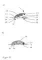
- control unit 12 is to be explained in more detail with reference to FIG. 2.
- control unit 12 contains 5 designed as membrane switches Printing unit direct selection keys 16, 17, 18, 19, 20. This corresponds to so many Keys as the printing press can have a maximum of printing units.
- the printing press only two Has printing units, only two controls 16, 17 for Direct control of the two printing units required.
- the cover frame consists of an outer frame 21 and an inner cover 22.
- the outer frame 21 has a spacious opening 23, all of which the keyboard 12 arranged controls 16, 17, 18, 19, 20 leaves free.
- the outer frame 21 is firmly and permanently connected to the keyboard 12. He is either mounted on the keyboard 12 or this extensively. At further consideration is to assume that the Outer frame 21 is arranged on the keyboard 12.
- the cover frame has an inner cover 22 on.
- This inner cover 22 consists of several segments 24, 25, 26, which are separated from one another by predetermined breaking points 27, the size each individual segment 24, 25, 26 is selected so that exactly one of the Keys 16, 17, 18, 19, 20 of the keyboard 12 is covered.
- the first latch 30 on the keyboard 12 opposite Outer frame 21 has a bore 32 into which a second latch 37, the is formed on the inner cover 22, engages.
- This second latch 37 passes through both the second bore 29 of the keyboard 12 and bore 32 of the outer frame 21, which is congruent with the overlying bore 29 of the outer frame 21 is arranged.
- the second Latch 37 of the inner frame 22 on the opposite side of the Keyboard 12 permanently connected to a counterpart 33.
- the second latch 37 thus simultaneously secures the outer frame 21 and the inner cover 22 on the keyboard 12 by the outer frame 21 is firmly clamped between the inner cover 22 and the keyboard 12.
- the holes 28, 29 of the keyboard 12 and the hole 32 of the Outer frame 21 are at equal intervals along the length of the Control unit 12 arranged in such a way that it can be fastened each segment 24, 25, 26 of the inner cover 22 are available.
- Identification of the individual operating elements 16, 17 MEMO elements 36 are used, which can be inserted into the respective bore 32.
- colored MEMO elements 36 refer to the im assigned printing unit color to be printed.
- the cover 21, 22 of the control unit 12 according to the invention is not open Keyboards with membrane keys limited. It is also conceivable that the Control elements are formed from one user interface, which is divided into several Areas is divided. These areas form different controls, where each control element is a command with rigid meaning generated, which is identified by a symbol. The command entry is done by touching the corresponding field on the user interface.
Landscapes
- Accessory Devices And Overall Control Thereof (AREA)
- Inking, Control Or Cleaning Of Printing Machines (AREA)
- Screen Printers (AREA)
- Control Of Electric Motors In General (AREA)
- Control Of Multiple Motors (AREA)
Abstract
Description
Die Anpassung der Tastaturgruppe an die in der Druckmaschine benötigten Bedienelemente erfolgt dabei einfach durch Veränderung der Innenabdeckung.
Die Innenabdeckung ist dabei derart ausgeformt, dass die erste Seite der Innenabdeckung den Rahmen formschlüssig untergreift.
Durch diese Ausgestaltung wird die Anzahl der Befestigungselemente für den Rahmen und die Innenabdeckung reduziert, ein Ablösen der Innenabdeckung vom Rahmen aber zuverlässig verhindert.
- Figur 1:
- Steuereinrichtung einer Druckmaschine
- Figur 2:
- Bedieneinheit der Steuereinrichtung
- Figur 3:
- Schnitt durch die Bedieneinheit
In Figur 1 ist das Prinzip einer Direktsteuerung zweier Druckwerke einer Bogenoffsetdruckmaschine dargestellt. Jede Steuereinrichtung 1, 1' eines Druckwerkes besteht aus einer Recheneinheit 2, 2', welche über eine interne, bidirektionale Datenleitung 3, 3' und über eine Schnittstelle 4, 4' mit Sensoren und Stellelementen des nicht weiter dargestellten Druckwerkes der Druckmaschine verbunden ist. Der Übersichtlichkeit halber sind in Figur 1 nur ein Sensor 5, 5' und ein Stellelement 6, 6' dargestellt.
Über eine interne Datenleitung 7, 7' ist die Recheneinheit 2, 2' mit einer zweiten Schnittstelle 8, 8' verbunden, an welche über eine Steuerleitung 9 eine Bedieneinheit 10 für beide Druckwerke angeschlossen ist.
Über eine Datenleitung 14 ist die Recheneinheit 11 mit der Tastatur 12 verbunden. Die Anzeige 13 wird von der Recheneinheit 11 über die Leitung 15 angesteuert.
- 1, 1'
- Steuereinrichtung
- 2, 2'
- Recheneinheit
- 3, 3'
- bidirektionale Datenleitung
- 4, 4'
- Schnittstelle
- 5, 5'
- Sensor
- 6,6'
- Stellelement
- 7, 7'
- interne Datenleitung
- 8, 8'
- Schnittstelle
- 9
- Steuerleitung
- 10
- Bedieneinheit
- 11
- Recheneinheit
- 12
- Tastatur
- 13
- Anzeige
- 14
- Datenleitung
- 15
- Datenleitung
- 16
- Druckwerkdirektanwahltaste
- 17
- Druckwerkdirektanwahltaste
- 18
- Druckwerkdirektanwahltaste
- 19
- Druckwerkdirektanwahltaste
- 20
- Druckwerkdirektanwahltaste
- 21
- Außenrahmen
- 22
- Innenabdeckung
- 23
- Öffnung des Außenrahmens
- 24
- Segment der Innenabdeckung
- 25
- Segment der Innenabdeckung
- 26
- Segment der Innenabdeckung
- 27
- Sollbruchstelle
- 28
- Bohrung der Tastatur
- 29
- Bohrung der Tastatur
- 30
- Rastnase des Außenrahmens
- 31
- Aufnahme der Rastnase
- 32
- Bohrung des Außenrahmens
- 33
- Aufnahme der Rastnase
- 34
- Vorsprung der Innenabdeckung
- 35
- Ausnehmung des Außenrahmens
- 36
- MEMO-Element
- 37
- Rastnase der Innenabdeckung
Claims (11)
- Bedieneinheit zur Ansteuerung einer Druckmaschine, insbesondere einer Bogenoffsetdruckmaschine, welche mehrere Bedienelemente zur Befehlseingabe für die aus mehreren Teileinheiten bestehende Druckmaschine aufweist, wobei die Bedienelemente auf einem gemeinsamen Träger angeordnet sind und jedem Bedienelement ein fester Kommandoinhalt zugeordnet ist, dadurch gekennzeichnet, dass eine maximale Anzahl der Bedienelemente (16, 17, 18, 19, 20) auf dem Träger (12) ausgebildet ist und eine Abdeckung (21, 22) der Bedienelemente ( 16, 17, 18, 19, 20) unlösbar auf oder an dem Träger (12) montiert ist, wobei eine vorgegebene, von den anzusteuernden Teileinheiten (1, 1') der Druckmaschine bestimmte Anzahl der Bedienelemente (16, 17, 18, 19, 20) von der Abdeckung (21, 22) unbedeckt bleibt.
- Bedieneinheit nach Anspruch 1 dadurch gekennzeichnet, dass die Abdeckung (21, 22) zweiteilig ausgebildet ist, wobei ein Rahmen (21) alle Bedienelemente (16, 17, 18, 19, 20) umschließend auf dem Träger (12) befestigt ist und an dem Rahmen (12) eine in der Überdeckung der Bedienelemente (16, 17, 18, 19, 20) variabel gestaltbare Innenabdeckung (22) angeordnet ist.
- Bedieneinheit nach Anspruch 2 dadurch gekennzeichnet, dass die Innenabdeckung (22) segmentartig ausgebildet ist, wobei jedes Segment (24, 25, 26) eine ein Bedienelement ( 16, 17, 18, 19, 20) überspannende Ausdehnung aufweist und die Segmente(24, 25, 26) untereinander mechanisch trennbar sind.
- Bedieneinheit nach Anspruch 3 dadurch gekennzeichnet, dass die nebeneinander angeordneten Segmente (24, 25, 26) an Sollbruchstellen (27) trennbar sind.
- Bedieneinheit nach Anspruch 2 dadurch gekennzeichnet, dass der Rahmen (21) einseitig fest mit dem Träger (12) der Bedienelemente (16, 17, 18, 19, 20) verbunden ist.
- Bedieneinheit nach Anspruch 2 und 5 dadurch gekennzeichnet, dass eine erste Seite der Innenabdeckung (22) am Rahmen (21) arretiert ist, während eine gegenüberliegende zweite Seite der Innenabdeckung (22) die unbefestigte Seite des Rahmens (21) einklemmend am Träger (12) befestigt ist.
- Bedieneinheit nach Anspruch 6 dadurch gekennzeichnet, dass die erste Seite der Innenabdeckung (22) den Rahmen (21) formschlüssig untergreift.
- Bedieneinheit nach Anspruch 3 und 6 dadurch gekennzeichnet, dass jedes Segment (24, 25, 26) der Innenabdeckung (22) eine Rasteinrichtung (37) aufweist, welche durch eine zugeordnete Öffnung (32) des Rahmens (21) hindurchgreifend fest an dem Träger (12) verankert ist.
- Bedieneinheit nach Anspruch 8 dadurch gekennzeichnet, dass der Rahmen (21) entlang seiner Längsausdehnung mehrere Öffnungen (32) in gleichmäßigen Abständen aufweist, wobei jede Öffnung (32) über oder unter einem Bedienelement ( 16, 17, 18, 19, 20) angeordnet ist und die Rasteinrichtungen (32) der die unbenötigten Bedienelemente ( 18, 19, 20) abdeckenden Segmente (24, 25, 26) der Innenabdeckung (22) in die Öffnungen (32) des Rahmens (21) eingreifen.
- Bedieneinheit nach Anspruch 9 dadurch gekennzeichnet, dass die freibleibenden Öffnungen des Rahmens Informationsträger (36) aufnehmen, welche die Bedienelemente ( 16, 17, 18, 19, 20) und/oder die jeweilige Teileinheit (1, 1') der Druckmaschine kennzeichnen.
- Bedieneinheit nach einem der vorhergehenden Ansprüche dadurch gekennzeichnet, dass die Bedienelemente ( 16, 17, 18, 19, 20) von einer Eingabefläche gebildet werden, wobei definierte Felder der Eingabefläche als Bedienelement ausgebildet sind und die Befehlseingabe durch Annäherung und/oder Berührung des entsprechenden Feldes der Eingabefläche erfolgt.
Applications Claiming Priority (2)
| Application Number | Priority Date | Filing Date | Title |
|---|---|---|---|
| DE20007280U DE20007280U1 (de) | 2000-04-20 | 2000-04-20 | Bedieneinheit zur Ansteuerung einer Druckmaschine |
| DE20007280U | 2000-04-20 |
Publications (3)
| Publication Number | Publication Date |
|---|---|
| EP1147895A2 true EP1147895A2 (de) | 2001-10-24 |
| EP1147895A3 EP1147895A3 (de) | 2003-09-10 |
| EP1147895B1 EP1147895B1 (de) | 2006-12-20 |
Family
ID=7940542
Family Applications (1)
| Application Number | Title | Priority Date | Filing Date |
|---|---|---|---|
| EP01109265A Expired - Lifetime EP1147895B1 (de) | 2000-04-20 | 2001-04-14 | Bedieneinheit zur Ansteuerung einer Druckmaschine |
Country Status (3)
| Country | Link |
|---|---|
| EP (1) | EP1147895B1 (de) |
| AT (1) | ATE348708T1 (de) |
| DE (2) | DE20007280U1 (de) |
Cited By (1)
| Publication number | Priority date | Publication date | Assignee | Title |
|---|---|---|---|---|
| EP2870095B1 (de) | 2012-07-05 | 2016-06-15 | Koenig & Bauer AG | Rollenversorgungssystem einer rollendruckmaschine, rollendruckmaschine sowie verfahren zur bedienung eines rollenversorgungssystems einer rollendruckmaschine |
Family Cites Families (6)
| Publication number | Priority date | Publication date | Assignee | Title |
|---|---|---|---|---|
| DD127024A1 (de) * | 1976-02-27 | 1977-08-31 | ||
| DE2932623A1 (de) * | 1979-08-11 | 1981-02-19 | Mergenthaler Linotype Gmbh | Tastatur mit einem ueberdecker ueber wenigstens einer taste, insbesondere eines textbearbeitungs- und/oder fotosatzgeraets |
| DE4306098A1 (de) * | 1993-02-27 | 1994-09-01 | Heidelberger Druckmasch Ag | Einrichtung zum Steuern einzelner Funktionseinheiten einer Druckmaschine |
| DE19746323A1 (de) * | 1997-10-21 | 1999-04-22 | Heidelberger Druckmasch Ag | Verfahren und Vorrichtung zum Einschalten einer Maschine |
| DE29802209U1 (de) * | 1998-02-10 | 1998-03-19 | MAN Roland Druckmaschinen AG, 63075 Offenbach | Bedienelement für eine Druckmaschine |
| DE29816392U1 (de) * | 1998-09-12 | 1998-12-17 | MAN Roland Druckmaschinen AG, 63075 Offenbach | Bedieneinheit für eine Steuereinrichtung einer Druckmaschine |
-
2000
- 2000-04-20 DE DE20007280U patent/DE20007280U1/de not_active Expired - Lifetime
-
2001
- 2001-04-14 AT AT01109265T patent/ATE348708T1/de not_active IP Right Cessation
- 2001-04-14 DE DE50111662T patent/DE50111662D1/de not_active Expired - Lifetime
- 2001-04-14 EP EP01109265A patent/EP1147895B1/de not_active Expired - Lifetime
Cited By (1)
| Publication number | Priority date | Publication date | Assignee | Title |
|---|---|---|---|---|
| EP2870095B1 (de) | 2012-07-05 | 2016-06-15 | Koenig & Bauer AG | Rollenversorgungssystem einer rollendruckmaschine, rollendruckmaschine sowie verfahren zur bedienung eines rollenversorgungssystems einer rollendruckmaschine |
Also Published As
| Publication number | Publication date |
|---|---|
| DE50111662D1 (de) | 2007-02-01 |
| ATE348708T1 (de) | 2007-01-15 |
| DE20007280U1 (de) | 2000-08-03 |
| EP1147895B1 (de) | 2006-12-20 |
| EP1147895A3 (de) | 2003-09-10 |
Similar Documents
| Publication | Publication Date | Title |
|---|---|---|
| EP0898003B1 (de) | Multifunktions-Bedienvorrichtung für Waschmaschinen | |
| EP1459895B1 (de) | Vorrichtung zum Einschalten einer Maschine | |
| DE102006052646A1 (de) | Druckmaschine mit mehreren Bedienzonen | |
| EP1105292B1 (de) | Vorrichtung zum einziehen einer bedruckstoffbahn | |
| DE3032282C2 (de) | Tastenschalter mit einem Tastengehäuse zum Einbau in einer mit Ausnehmungen versehenen Trageplatte von Tastaturen in Schreibmaschinen | |
| EP1049605B1 (de) | Stockschalter, insbesondere lenkstockschalter für kraftfahrzeuge | |
| EP1147895B1 (de) | Bedieneinheit zur Ansteuerung einer Druckmaschine | |
| DE10305123B4 (de) | Verfahren zum Herstellen einer Drucktasteneinheit | |
| EP0990519B1 (de) | Bedieneinheit für eine Steuereinrichtung einer Druckmaschine | |
| EP1381514A1 (de) | Steuereinrichtung für mehrfarbdruckmaschinen | |
| DE3436811A1 (de) | Verfahren und anordnung zum einstellen der betriebsparameter eines druckwerkes oder dergleichen | |
| EP2178098B1 (de) | Schalter | |
| EP1433606B1 (de) | Vorrichtung und ein Verfahren zum Bedienen einer Druckmaschine | |
| DE102004046903A1 (de) | Vorrichtung zur Auslösung eines Abfragesignals | |
| EP1223484B1 (de) | Installationsgerät für den Anschluss an EIB-Busleitungen | |
| EP0802086A2 (de) | Multifunktions-Bedieneinrichtung | |
| EP0703181A2 (de) | Ein- und Ausgabesystem für Aufzugssteuerungen | |
| DE102007022345A1 (de) | Helligkeitssteuerung einer Beleuchtungseinrichtung mit einem Dimmer | |
| DE3622275A1 (de) | Mehrfunktionstastatur | |
| DE3900003C2 (de) | Bedienvorrichtung für Geräte, insbesondere für Funkgeräte | |
| EP1723440B1 (de) | Dynamische verwaltung eines tastaturspeichers | |
| EP2212458B1 (de) | Nähmaschine mit einer schaltereinrichtung | |
| EP1837738A1 (de) | Mobiles Datenverarbeitungs-Handgerät | |
| DE102009058640B4 (de) | Bedieneinheit und Verfahren zum Bedienen einer Bedieneinheit | |
| EP0730958A2 (de) | Sicherheitseinrichtung für eine Druckmaschine |
Legal Events
| Date | Code | Title | Description |
|---|---|---|---|
| PUAI | Public reference made under article 153(3) epc to a published international application that has entered the european phase |
Free format text: ORIGINAL CODE: 0009012 |
|
| AK | Designated contracting states |
Kind code of ref document: A2 Designated state(s): AT BE CH CY DE DK ES FI FR GB GR IE IT LI LU MC NL PT SE TR |
|
| AX | Request for extension of the european patent |
Free format text: AL;LT;LV;MK;RO;SI |
|
| PUAL | Search report despatched |
Free format text: ORIGINAL CODE: 0009013 |
|
| AK | Designated contracting states |
Kind code of ref document: A3 Designated state(s): AT BE CH CY DE DK ES FI FR GB GR IE IT LI LU MC NL PT SE TR |
|
| AX | Request for extension of the european patent |
Extension state: AL LT LV MK RO SI |
|
| RIC1 | Information provided on ipc code assigned before grant |
Ipc: 7G 06F 3/02 B Ipc: 7B 41F 33/00 A |
|
| 17P | Request for examination filed |
Effective date: 20030802 |
|
| AKX | Designation fees paid |
Designated state(s): AT BE CH CY DE DK ES FI FR GB GR IE IT LI LU MC NL PT SE TR |
|
| GRAP | Despatch of communication of intention to grant a patent |
Free format text: ORIGINAL CODE: EPIDOSNIGR1 |
|
| GRAS | Grant fee paid |
Free format text: ORIGINAL CODE: EPIDOSNIGR3 |
|
| GRAA | (expected) grant |
Free format text: ORIGINAL CODE: 0009210 |
|
| AK | Designated contracting states |
Kind code of ref document: B1 Designated state(s): AT BE CH CY DE DK ES FI FR GB GR IE IT LI LU MC NL PT SE TR |
|
| PG25 | Lapsed in a contracting state [announced via postgrant information from national office to epo] |
Ref country code: IT Free format text: LAPSE BECAUSE OF FAILURE TO SUBMIT A TRANSLATION OF THE DESCRIPTION OR TO PAY THE FEE WITHIN THE PRESCRIBED TIME-LIMIT;WARNING: LAPSES OF ITALIAN PATENTS WITH EFFECTIVE DATE BEFORE 2007 MAY HAVE OCCURRED AT ANY TIME BEFORE 2007. THE CORRECT EFFECTIVE DATE MAY BE DIFFERENT FROM THE ONE RECORDED. Effective date: 20061220 Ref country code: DK Free format text: LAPSE BECAUSE OF FAILURE TO SUBMIT A TRANSLATION OF THE DESCRIPTION OR TO PAY THE FEE WITHIN THE PRESCRIBED TIME-LIMIT Effective date: 20061220 Ref country code: FI Free format text: LAPSE BECAUSE OF FAILURE TO SUBMIT A TRANSLATION OF THE DESCRIPTION OR TO PAY THE FEE WITHIN THE PRESCRIBED TIME-LIMIT Effective date: 20061220 Ref country code: IE Free format text: LAPSE BECAUSE OF FAILURE TO SUBMIT A TRANSLATION OF THE DESCRIPTION OR TO PAY THE FEE WITHIN THE PRESCRIBED TIME-LIMIT Effective date: 20061220 Ref country code: NL Free format text: LAPSE BECAUSE OF FAILURE TO SUBMIT A TRANSLATION OF THE DESCRIPTION OR TO PAY THE FEE WITHIN THE PRESCRIBED TIME-LIMIT Effective date: 20061220 |
|
| REG | Reference to a national code |
Ref country code: GB Ref legal event code: FG4D Free format text: NOT ENGLISH |
|
| REG | Reference to a national code |
Ref country code: CH Ref legal event code: EP |
|
| REF | Corresponds to: |
Ref document number: 50111662 Country of ref document: DE Date of ref document: 20070201 Kind code of ref document: P |
|
| REG | Reference to a national code |
Ref country code: IE Ref legal event code: FG4D Free format text: LANGUAGE OF EP DOCUMENT: GERMAN |
|
| PG25 | Lapsed in a contracting state [announced via postgrant information from national office to epo] |
Ref country code: SE Free format text: LAPSE BECAUSE OF FAILURE TO SUBMIT A TRANSLATION OF THE DESCRIPTION OR TO PAY THE FEE WITHIN THE PRESCRIBED TIME-LIMIT Effective date: 20070320 |
|
| PG25 | Lapsed in a contracting state [announced via postgrant information from national office to epo] |
Ref country code: ES Free format text: LAPSE BECAUSE OF FAILURE TO SUBMIT A TRANSLATION OF THE DESCRIPTION OR TO PAY THE FEE WITHIN THE PRESCRIBED TIME-LIMIT Effective date: 20070331 |
|
| PG25 | Lapsed in a contracting state [announced via postgrant information from national office to epo] |
Ref country code: PT Free format text: LAPSE BECAUSE OF FAILURE TO SUBMIT A TRANSLATION OF THE DESCRIPTION OR TO PAY THE FEE WITHIN THE PRESCRIBED TIME-LIMIT Effective date: 20070423 |
|
| NLV1 | Nl: lapsed or annulled due to failure to fulfill the requirements of art. 29p and 29m of the patents act | ||
| GBV | Gb: ep patent (uk) treated as always having been void in accordance with gb section 77(7)/1977 [no translation filed] |
Effective date: 20061220 |
|
| EN | Fr: translation not filed | ||
| PLBE | No opposition filed within time limit |
Free format text: ORIGINAL CODE: 0009261 |
|
| STAA | Information on the status of an ep patent application or granted ep patent |
Free format text: STATUS: NO OPPOSITION FILED WITHIN TIME LIMIT |
|
| PG25 | Lapsed in a contracting state [announced via postgrant information from national office to epo] |
Ref country code: GB Free format text: LAPSE BECAUSE OF FAILURE TO SUBMIT A TRANSLATION OF THE DESCRIPTION OR TO PAY THE FEE WITHIN THE PRESCRIBED TIME-LIMIT Effective date: 20061220 |
|
| 26N | No opposition filed |
Effective date: 20070921 |
|
| REG | Reference to a national code |
Ref country code: CH Ref legal event code: PL |
|
| BERE | Be: lapsed |
Owner name: MAN ROLAND DRUCKMASCHINEN A.G. Effective date: 20070430 |
|
| PG25 | Lapsed in a contracting state [announced via postgrant information from national office to epo] |
Ref country code: CH Free format text: LAPSE BECAUSE OF NON-PAYMENT OF DUE FEES Effective date: 20070430 Ref country code: LI Free format text: LAPSE BECAUSE OF NON-PAYMENT OF DUE FEES Effective date: 20070430 |
|
| PG25 | Lapsed in a contracting state [announced via postgrant information from national office to epo] |
Ref country code: BE Free format text: LAPSE BECAUSE OF NON-PAYMENT OF DUE FEES Effective date: 20070430 |
|
| PG25 | Lapsed in a contracting state [announced via postgrant information from national office to epo] |
Ref country code: FR Free format text: LAPSE BECAUSE OF FAILURE TO SUBMIT A TRANSLATION OF THE DESCRIPTION OR TO PAY THE FEE WITHIN THE PRESCRIBED TIME-LIMIT Effective date: 20070810 Ref country code: GR Free format text: LAPSE BECAUSE OF FAILURE TO SUBMIT A TRANSLATION OF THE DESCRIPTION OR TO PAY THE FEE WITHIN THE PRESCRIBED TIME-LIMIT Effective date: 20070321 |
|
| PG25 | Lapsed in a contracting state [announced via postgrant information from national office to epo] |
Ref country code: FR Free format text: LAPSE BECAUSE OF FAILURE TO SUBMIT A TRANSLATION OF THE DESCRIPTION OR TO PAY THE FEE WITHIN THE PRESCRIBED TIME-LIMIT Effective date: 20061220 |
|
| PG25 | Lapsed in a contracting state [announced via postgrant information from national office to epo] |
Ref country code: MC Free format text: LAPSE BECAUSE OF NON-PAYMENT OF DUE FEES Effective date: 20070430 |
|
| PG25 | Lapsed in a contracting state [announced via postgrant information from national office to epo] |
Ref country code: LU Free format text: LAPSE BECAUSE OF NON-PAYMENT OF DUE FEES Effective date: 20070414 Ref country code: CY Free format text: LAPSE BECAUSE OF FAILURE TO SUBMIT A TRANSLATION OF THE DESCRIPTION OR TO PAY THE FEE WITHIN THE PRESCRIBED TIME-LIMIT Effective date: 20061220 |
|
| PG25 | Lapsed in a contracting state [announced via postgrant information from national office to epo] |
Ref country code: TR Free format text: LAPSE BECAUSE OF FAILURE TO SUBMIT A TRANSLATION OF THE DESCRIPTION OR TO PAY THE FEE WITHIN THE PRESCRIBED TIME-LIMIT Effective date: 20061220 |
|
| PGFP | Annual fee paid to national office [announced via postgrant information from national office to epo] |
Ref country code: AT Payment date: 20100415 Year of fee payment: 10 |
|
| PGFP | Annual fee paid to national office [announced via postgrant information from national office to epo] |
Ref country code: DE Payment date: 20110421 Year of fee payment: 11 |
|
| REG | Reference to a national code |
Ref country code: AT Ref legal event code: MM01 Ref document number: 348708 Country of ref document: AT Kind code of ref document: T Effective date: 20110414 |
|
| PG25 | Lapsed in a contracting state [announced via postgrant information from national office to epo] |
Ref country code: AT Free format text: LAPSE BECAUSE OF NON-PAYMENT OF DUE FEES Effective date: 20110414 |
|
| REG | Reference to a national code |
Ref country code: DE Ref legal event code: R081 Ref document number: 50111662 Country of ref document: DE Owner name: MANROLAND SHEETFED GMBH, DE Free format text: FORMER OWNER: MANROLAND AG, 63075 OFFENBACH, DE Effective date: 20120509 |
|
| REG | Reference to a national code |
Ref country code: DE Ref legal event code: R119 Ref document number: 50111662 Country of ref document: DE Effective date: 20121101 |
|
| PG25 | Lapsed in a contracting state [announced via postgrant information from national office to epo] |
Ref country code: DE Free format text: LAPSE BECAUSE OF NON-PAYMENT OF DUE FEES Effective date: 20121101 |