EP1147745A2 - Dispositif pour l'expansion du palais - Google Patents
Dispositif pour l'expansion du palais Download PDFInfo
- Publication number
- EP1147745A2 EP1147745A2 EP01109650A EP01109650A EP1147745A2 EP 1147745 A2 EP1147745 A2 EP 1147745A2 EP 01109650 A EP01109650 A EP 01109650A EP 01109650 A EP01109650 A EP 01109650A EP 1147745 A2 EP1147745 A2 EP 1147745A2
- Authority
- EP
- European Patent Office
- Prior art keywords
- bone
- extension part
- bone support
- clamping
- extension
- Prior art date
- Legal status (The legal status is an assumption and is not a legal conclusion. Google has not performed a legal analysis and makes no representation as to the accuracy of the status listed.)
- Granted
Links
Images


Classifications
-
- A—HUMAN NECESSITIES
- A61—MEDICAL OR VETERINARY SCIENCE; HYGIENE
- A61B—DIAGNOSIS; SURGERY; IDENTIFICATION
- A61B17/00—Surgical instruments, devices or methods, e.g. tourniquets
- A61B17/56—Surgical instruments or methods for treatment of bones or joints; Devices specially adapted therefor
- A61B17/58—Surgical instruments or methods for treatment of bones or joints; Devices specially adapted therefor for osteosynthesis, e.g. bone plates, screws, setting implements or the like
- A61B17/60—Surgical instruments or methods for treatment of bones or joints; Devices specially adapted therefor for osteosynthesis, e.g. bone plates, screws, setting implements or the like for external osteosynthesis, e.g. distractors, contractors
- A61B17/66—Alignment, compression or distraction mechanisms
- A61B17/663—Alignment, compression or distraction mechanisms for jaw bones, e.g. subcutaneous distractors with external access
-
- A—HUMAN NECESSITIES
- A61—MEDICAL OR VETERINARY SCIENCE; HYGIENE
- A61C—DENTISTRY; APPARATUS OR METHODS FOR ORAL OR DENTAL HYGIENE
- A61C7/00—Orthodontics, i.e. obtaining or maintaining the desired position of teeth, e.g. by straightening, evening, regulating, separating, or by correcting malocclusions
- A61C7/10—Devices having means to apply outwardly directed force, e.g. expanders
-
- A—HUMAN NECESSITIES
- A61—MEDICAL OR VETERINARY SCIENCE; HYGIENE
- A61C—DENTISTRY; APPARATUS OR METHODS FOR ORAL OR DENTAL HYGIENE
- A61C8/00—Means to be fixed to the jaw-bone for consolidating natural teeth or for fixing dental prostheses thereon; Dental implants; Implanting tools
- A61C8/0093—Features of implants not otherwise provided for
- A61C8/0096—Implants for use in orthodontic treatment
Definitions
- the present invention relates to a device for the palate extension with a in its length dimension extendable and / or shortenable extension part, the both ends have a fixing part.
- Such a device also referred to as a distractor, is an orthodontic surgical device Apparatus that allows gradual, i.e. gradual extension rapidly expand the upper jaw in width or gradually add two other bone segments, in the sense of a distraction to move apart.
- the apparatus can also an enlargement of the upper jaw can be used in one step to determine the position of the to be able to precisely adjust both halves of the palate to each other and to the lower jaw. This can lead to occlusion disorders, malformations, bone asymmetries and mismatches between upper and lower jaw are corrected, which are congenital or acquired could be.
- the first main application the so-called rapid palate expansion, works therefore, an insufficient width of the upper jaw due to an orthodontic orthodontic Correct treatment so that the relationship between maxillary and mandibular arch is normalized.
- the upper jaw consists of a left and a right half, which are united in the mid-sagittal plane in the palate seam. In patients under the age of 12-14 years, this connection is generally still not ossified over a large area, so that the two are gradually separated Halves the orthognathic correction is easy to do. In older adolescents or adults, the seam has grown together to an increasing extent. In these cases, surgical support is often necessary by adding parts of the upper jaw are weakened so that the suture can be opened again, to then carry out the gradual widening.
- the conventional distraction of bone segments in any direction it's about bone dimensions that are too small enlarge.
- a typical example is the too short horizontal part of the lower jaw, the results in an overjet (overbite) with the associated orthodontic complications and the aesthetic problems with the face profile.
- overjet overbite
- a jaw surgery The bone is severed and bridged by the distractor. After a short healing period of a few days, this becomes the separation point bridging healing tissue, the callus, gradually distracts, i.e. the bone compartments moved apart by means of the distractor.
- such devices are only used intraoperatively to position to be able to precisely adjust parts of the upper jaw against each other, e.g. in the case a cleft lip and palate. This attitude is very much without such help difficult because of the tensile forces exerted by the soft parts.
- the desired one After checking the occlusion with the lower jaw, the bone parts become position screwed in the position achieved and the device is then again away.
- WO 94/10933 describes a distractor that can be found both on teeth and also supported on palate plates.
- a disadvantage of periodontal support is also that the two halves of the palate can tilt in the existing supports in the frontal plane instead of to move apart in a stable angular position in the frontal view.
- the present invention has for its object to provide a distractor that the above-mentioned disadvantages of known distractors, especially those that leaning on the tooth, at least partially avoiding it.
- a device for the palate extension with an in its length dimension extendable and / or shortenable extension part that its two ends each have a fixing part, which is characterized in that each fixing part is constructed as a punctiform bone support part.
- Such a distractor avoids palate plates or supports on the teeth that have the disadvantages indicated above by the expansion part over the Bone fixation parts and support punctiform.
- a stab incision in the palate mucosa either screwed special anchoring screws into the bone or the support parts are designed as a mandrel.
- Such support parts can be placed on the bone practically at any position and thus fixed, regardless of the position of the teeth, which in no way as Retaining means for such extension parts are needed.
- there are no special adjustments be made for each patient such as this is the case with palate plates or teeth.
- the device axes can be placed so that not only an enlargement of the palate, but at the same time an extension, if this is necessary.
- the bone support part can be connected to the extension part via a adjustable joint that can be fixed in its position; with this connection A moment can be transmitted between the extension part and the bone support / screw if necessary, by in one variant the joint on the fastening unit is clamped, while in another variant it is rigid.
- Such thickenings which in a further embodiment are plate-like or bead-like have the additional advantage that they grow into the mucous membrane can, so that there is a positive connection.
- this ingrowth has Advantage that the bone support part is held in position and does not fall off can.
- extension part there are at least three threaded elements for this provided that screwed together two opposing pairs of threads form, with a rotation of the central threaded element in one or the extended or shortened the extension part in the other direction of rotation.
- Such extension parts can be easily extended or shortened despite their simple structure; the Amount of an extension or a shortening per revolution of the thread can be about be specified by the thread pitch.
- the extension part is made of at least three elements. These three elements are interconnected, the the first element is sleeve-shaped and rotatably supported therein the second element records. The third element is screwed to the second element so that under Rotation of the second element in one direction or in the other direction the third element is pulled into or pushed out of the first element and thus the extension part is shortened or lengthened.
- the respective clamping part on the extension part can be released and are slidably disposed so that the bone support member held therein can be moved together with this clamping part.
- the clamping part on the extension part is also detachable and slidably arranged.
- one Pressure area is provided, on which a corresponding tool is attached.
- Such one Tool can be a pair of pliers between the two opposite one another Pressure surfaces of the two bone support parts are inserted and spread, so that the bone support parts are shifted towards the bone.
- a rough setting can be made to to position the distractor while the fine drive then extends over the Threaded rods is made.
- Such a pressure surface on the bone support part can be formed as a depression, so that a corresponding slipping off tool attached to it is prevented.
- the joint with which the respective bone support part on the extension part is preferred is connected to be formed by a ball joint, the ball of the joint is assigned to the bone support part, while the extension part has a corresponding one Ball socket for receiving this ball and for clamping and holding the Ball.
- a ball joint which is either held or rotatable can be jammed in the bearing pan, allows adjustment of the distractor so that the bone support elements do not only move apart linearly.
- the ball head can be a variant between the bony support and the extension part not be tightened or temporarily loosened, which then Allow the bone segments to adjust their angle to each other easily and thus, for example the TMJ heads in the midline distraction of the lower jaw in the Pan remain, so there are no problems in the patient's temporomandibular joints occur.
- the clamping parts mentioned above can be designed so that they each have a threaded element of the extension part.
- the respective threaded element of the Clamping part be a sleeve with an internal thread, into which there is a corresponding threaded rod screwed in.
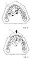
- FIG. 1a shows the anchoring of two distractors in a top view of a plaster model shown according to a first embodiment, wherein one of the distractors also in a view from the front in Figure 1b is shown.
- This distractor comprises two threaded elements 2, 3, one threaded element 3 being a sleeve-shaped one Part with an internal thread, while the other threaded element 2 is in the form of a threaded rod is constructed.
- Threaded rod 2 joint socket 4 is attached; a corresponding socket 5 is also at the end of the threaded sleeve 3 arranged.
- the two threaded elements 2, 3 form one in its length dimensions extendable and / or shortenable extension part, generally with the reference symbol 6 is designated.
- a bone support part in the form of a bone screw 7 is inserted; a such a bone screw 7 is shown in an enlarged view.
- These bone screws 7 comprise a threaded part 8, which has a support ring or a support washer 9 completes.
- a half part then closes on this support disk 9 10 to which an articulated ball 11 then connects.
- In the head area of the joint ball 11 there is a slot or cross slot 12 (or an inner polygon) around them Bone screw 7 in the bone with a standard surgical screwdriver to use, as shown in Figures 1a and 1b.
- the support disc 9 limits the possible penetration depth of the bone screw 7.
- the half part 10 serves for bridging the mucous membrane, so that the ball 11 is good outside the mucous membrane is accessible.
- a first application of the distractors 1 is the rapid, transverse expansion the palate seam, which is denoted by GN in Figures 1a and 1b.
- the respective extension parts 6 of the two distractors can then be extended by the threaded element or the threaded rod 3rd is rotated by means of a hexagon nut 13 arranged thereon in a rotationally fixed manner and thereby unscrews from the internal thread of the sleeve-shaped threaded element 2.
- the use of the distractor 1, as also shown in FIG Figures 1a and 1b is shown in an oblique arrangement in the palate to a Asymmetry of the alveolar process AF of the upper jaw, for example as a result of a cleft lip and palate (also called Hasenscharte) to compensate and the deformed Part of the alveolar process immediately against the pull of the soft parts in the correct position bring to.
- the distraction is continued until the bone parts are in the correct position Occlusion are aligned; afterwards the bone parts can be reached in the Position screwed together by means of suitable plates or screw elements, which are not shown become.
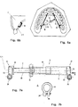
- FIG. 3 shows the use of a single distractor around a front segment, designated FS. to gradually move the upper jaw forward, for example by an imbalance to balance between the upper and lower teeth or by one resolve so-called frontal crowding, in which the teeth twist due to lack of space or nested.
- FS front segment
- the posterior Part of the hard palate designated PHG
- distractor 1 to the rear shifted, as indicated by the arrow.
- PHG posterior Part of the hard palate
- the arrangement of the distractor 1 is chosen here according to the arrangement of FIG. 3.
- FIG. 5 compared to the arrangement in FIG. 4, practically the entire alveolar process is shown AF detached from the rest of the upper jaw and gradually adjusted using distractor 1 distracts at the front, for example by mispositioning between the upper and lower teeth compensate.
- FIG. 6a a single distractor 1 is inserted around the upper jaw to broaden.
- the distractor is not placed on bone screws 7 with a ball head supported, but two brackets 14 are used; such a bracket is also shown in an enlarged view in Figure 9.
- the connection between distractor 1 or extension part 6 and bracket 14 takes place via connecting elements 15 (see FIG 6a), which is clamped at 16 on the cross bar part at any position and the same ball as the joint ball 11 of the bone screw 7 (see Figure 8) have, so that the extension part 6 can be used compatible.
- the bracket 14 has two U-shaped ends at the ends of the bracket cross part 16 Elements 17, each having a spinous process at the free ends of the two legs 18 have.
- the spinous process 18 is smaller in diameter at its base than the end face 19 of the legs of the U-shaped elements 17, so that a step arises, which limits the penetration of this bracket into the bone.
- the bracket cross member 16 is divided with a threaded connection or simple plug-in connection (without thread) so that the two halves against each other can be rotated to lengthen or shorten the bracket cross member 16 to be able to adapt to the respective circumstances.
- the extension parts 6, as used in FIGS. 1 to 6, are in an enlarged, detailed representation shown in Figures 7a and 7b.
- the extension part 6 of the distractor 1 is a combination of interlocking internal and external threaded rods or tubes or sleeves 2, 3.
- the threaded rod 3 again in a tube section 19 and a rod section 20 divided so that by screwing in of the rod section 20 in the tube section 19 a basic setting of the length of the extension part 6 can be achieved. Consequently, the rod section 20 has one External thread which engages in the tubular section 19 with an internal thread.
- the tube section 19 also has an external thread that fits into the sleeve-shaped threaded element 2 engages with internal thread.
- the two pairs of threads of parts 20/19 and 19/2 are constructed in opposite directions so that by turning the middle part 19 on the hexagon nut 13 the entire extension part 6 can either be shortened or expanded can.
- clamping parts 21 For connecting the extension part 6 to the bone screws 7 with the joint ball 11 takes place via clamping parts 21.
- the necessary elasticity to clamp the joint ball 11 is achieved by attaching it a slot 23 transverse to the longitudinal axis of the extension part 6, designated LA is achieved. The actual clamping then takes place via a screw connection 24, which can contract a slot 25 of the clamping part 21 to the joint ball 11 to clamp.
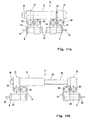
- FIG. 10 shows a further variant of the distractor, two in this illustration Possibilities of bone support parts can be seen.
- Extension part 6 is a threaded rod with two opposing threads 26, between which the hexagon nut 13 is placed to turn the threaded rod.
- a sleeve with a corresponding internal thread 27 is placed on each of the opposite thread 26, a sleeve with a corresponding internal thread 27 is placed.
- the extension part in one or the other direction can be extended or shortened.
- the Hexagon nut 13 radially extending bores 28 into which a handling tool can be inserted to turn the nut.
- a clamping part 21 is placed, which in its basic structure Clamping part corresponds, as shown in Figure 7b. From this clamping part 21 extends there is an arm 29 which is angled and at its end either a bone plate 9a for one or more standard bone screw (s) 7 (left side) or a mandrel 30 (right side) provided with support disks 9 to the depth of penetration of the bone support parts to limit.
- the mucous membrane is designated by SH.
- the Bone screw 7 is, as shown in Figure 10, by a stab incision in the Mucous membrane SH driven into the bone.
- the arms 29 are angled so that the Bone screw 7 or the mandrel 30 approximately orthograte to the corresponding bone surface hard palate can be driven.
- arms 29 with bone plates 9a is especially for thin bones from Advantage in which the special screw 2 according to FIG. 8 does not grip enough. Furthermore is outside due to the flexible positioning of the mandrel or the bone screws the direct axis of the distractor, there is more space for this, often narrow bulges of the palate, as this leads almost directly to the mucous membrane can be.
- FIGS. 11 a and 11 b show a further embodiment of a distractor with a in the basic structure three-part extension part 6 with a cylindrical sleeve part 31, with an extension part 32 and a threaded element guided in the sleeve part 31 35, which has a polygonal outer contour at its left, projecting end to turn this threaded element over this polygon.
- This threaded element 35 is screwed into the extension part 32, which has an internal thread, as with reference the broken lines can be seen, so that by turning the polygon the extension part 32 is pushed out of the sleeve part 31, i.e. extended, or can be drawn in, i.e. can be shortened.
- the sleeve part 31 is non-rotatable held.
- clamping parts 21 are fastened by means of screw connections 24 can be clamped.
- a second clamping part 21 is via a suitable cross connection connected to the first clamping part 21 and can on the cross connection be clamped by means of screw connection 24.
- this second clamping part 21 is a mandrel 30, which has a cylindrical extension part 32, is clamped.
- the cylindrical Extension part 33 can be in a suitable position on the associated one Clamping part 21 are clamped, so that the extension part 6 is cylindrical over this Extension part 33 can also be changed in its dimensions.
- FIG. 11a shows the distractor in a collapsed position with the smallest Dimension in the axial direction, while FIG. 11B extended the distractor to its maximum Position shows.
- the end faces are the cylindrical Extension parts 33, which face the mandrel 30, with a concave curvature 34 provided.
- the two domes 34 of the opposite cylindrical Extension parts 33 can be a tool, for example in the manner of pliers, engage to drive apart the respective cylindrical extension parts 33 and anchor the respective mandrels 30 in the bones at the appropriate locations before the extension part is extended by rotating the threaded rod 32.
- the axes of the extension part are closed offset the axes of the cylindrical extension parts 33, so that there is a structure, in which the extension part 6 is offset from the bone anchoring points.
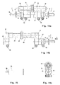
- FIGS. 12a to 12c corresponds to the distractor shown in FIG. 10.
- the clamping parts 21 are opposite 10 of the embodiment, constructed in such a way that it a bone screw 7, as shown in Figure 8, can take, and accordingly a structure as shown in Figure 7a.
- the clamping parts 21 can be used via the respective Clamping screws 36 are displaced and fixed on the sleeves 27, as by means of the different positions of the clamping parts 21 can be seen in FIGS. 12a and 12b is.
- the respective sleeve 27 and the respective clamping part 21 are via a positive connection connected so that the clamping part 21 does not fall off the sleeve 27 can.
- FIG. 13 shows the clamping part 21 as used in FIGS. 12a and 12b, however with a mandrel 30 and a cylindrical extension part 33, accordingly the embodiment of Figure 11b, which instead of the bone screw 7 of Figures 12a and 12b can be used if the distractor is not screwed into the bone should.
- each in turn counter-rotating external thread have, directly the clamping parts 21, the corresponding internal thread have put on. Otherwise, these clamping parts correspond to those in FIG. 13 are shown, although in the clamping parts 21 a specially designed cylindrical extension element 37 is provided, which at its outer end is provided by means of a clamping device to insert the joint ball 11 of a bone screw therein to record.
- the structure of this clamping part corresponds to that as in 7a is arranged at the two ends of the extension part 6 shown there.
- the cylindrical extension members 37 may be a cylindrical extension member 33 with mandrel 30, as shown in FIG. 15, are used, so that with this structure results in a large variability of the distractor.
- the distractors shown in Figures 11, 12 and 14 have one thing in common Feature the offset axes of the extension part 6 to the axes of the bone support elements in the form of the bone screws 7 or the thorns 30.
Landscapes
- Health & Medical Sciences (AREA)
- Orthopedic Medicine & Surgery (AREA)
- Life Sciences & Earth Sciences (AREA)
- Animal Behavior & Ethology (AREA)
- Veterinary Medicine (AREA)
- Surgery (AREA)
- Public Health (AREA)
- General Health & Medical Sciences (AREA)
- Engineering & Computer Science (AREA)
- Dentistry (AREA)
- Medical Informatics (AREA)
- Heart & Thoracic Surgery (AREA)
- Biomedical Technology (AREA)
- Nuclear Medicine, Radiotherapy & Molecular Imaging (AREA)
- Oral & Maxillofacial Surgery (AREA)
- Molecular Biology (AREA)
- Epidemiology (AREA)
- Surgical Instruments (AREA)
- Prostheses (AREA)
- Orthopedics, Nursing, And Contraception (AREA)
- Control And Other Processes For Unpacking Of Materials (AREA)
- Massaging Devices (AREA)
- Meat, Egg Or Seafood Products (AREA)
Applications Claiming Priority (2)
| Application Number | Priority Date | Filing Date | Title |
|---|---|---|---|
| CH8922000 | 2000-04-20 | ||
| CH8922000 | 2000-04-20 |
Publications (3)
| Publication Number | Publication Date |
|---|---|
| EP1147745A2 true EP1147745A2 (fr) | 2001-10-24 |
| EP1147745A3 EP1147745A3 (fr) | 2003-05-14 |
| EP1147745B1 EP1147745B1 (fr) | 2004-06-09 |
Family
ID=4545857
Family Applications (1)
| Application Number | Title | Priority Date | Filing Date |
|---|---|---|---|
| EP01109650A Expired - Lifetime EP1147745B1 (fr) | 2000-04-20 | 2001-04-19 | Dispositif pour l'expansion du palais |
Country Status (5)
| Country | Link |
|---|---|
| US (1) | US6592366B2 (fr) |
| EP (1) | EP1147745B1 (fr) |
| AT (1) | ATE268576T1 (fr) |
| DE (1) | DE50102514D1 (fr) |
| ES (1) | ES2222950T3 (fr) |
Cited By (10)
| Publication number | Priority date | Publication date | Assignee | Title |
|---|---|---|---|---|
| WO2007137439A1 (fr) * | 2006-05-26 | 2007-12-06 | Medartis Ag | Distracteur palatin oral |
| WO2007120119A3 (fr) * | 2006-04-17 | 2008-01-17 | Mustafa Ayan | Écarteur maxillaire automatique et appareil de transfert |
| US7347687B2 (en) * | 2002-01-23 | 2008-03-25 | Roger Minoretti | Distraction apparatus for orthodontic, orthognathic and oral/maxillofacial surgery applications on the mandible |
| WO2012019747A1 (fr) * | 2010-08-11 | 2012-02-16 | Schroeder Ludger | Pince pour crête maxillaire et dispositif pour écarter un os maxillaire |
| EP2594225A1 (fr) * | 2011-11-21 | 2013-05-22 | Promedia A. Ahnfeldt GmbH | Dispositif d'ancrage destiné à la fixation de fils orthodontiques ou d'appareils d'orthopédie maxillo-faciale pour les traitements de correction orthopédique de la mâchoire |
| EP2946745A1 (fr) * | 2003-09-16 | 2015-11-25 | Bredent Dentalgeräte und Materialien Fach- und Organisationsberatung Peter Brehm | Vis de positionnement pour produire une prothese dentaire pour une machoire partiellement ou completement depourvue de dents |
| CN105476703A (zh) * | 2015-12-25 | 2016-04-13 | 上海景堂医疗器械有限公司 | 下颌骨外固定桥 |
| EP3064167A1 (fr) * | 2015-03-05 | 2016-09-07 | Medicon Eg Chirurgiemechaniker-Genossenschaft | Kit d'expansion comprenant un dispositif d'expansion ou d'elongation {j}de segments osseux |
| EP3354226A1 (fr) * | 2017-01-27 | 2018-08-01 | Technische Universität Dresden | Dispositif séparateur, en particulier dispositif séparateur pour mâchoire supérieure |
| WO2020141134A1 (fr) | 2019-01-04 | 2020-07-09 | Forstgarten International Holding Gmbh | Dispositif d'entraînement biomécanique pour l'articulation maxillaire |
Families Citing this family (31)
| Publication number | Priority date | Publication date | Assignee | Title |
|---|---|---|---|---|
| US20110287378A1 (en) | 2002-10-29 | 2011-11-24 | Rmo, Inc. | Orthodontic appliance with encoded information formed in the base |
| US7655048B2 (en) * | 2003-04-02 | 2010-02-02 | Furlow Jr Leonard T | Materials and methods for soft tissue augmentation |
| US20050244779A1 (en) * | 2004-04-30 | 2005-11-03 | Norbert Abels | Method of correcting a deep bite condition using adjustable bite ramps |
| US7293987B2 (en) * | 2004-04-30 | 2007-11-13 | Norbert Abels | Adjustable bite ramps for deep bite correction and kits incorporating bite ramps |
| US20050244781A1 (en) * | 2004-04-29 | 2005-11-03 | Norbert Abels | Orthodontic treatment method for concurrent correction of multiple conditions |
| US7226287B2 (en) * | 2004-04-30 | 2007-06-05 | Ultradent Products, Inc. | Kits comprising a plurality of bite ramps having different angles for orthodontic treatment |
| US7331781B1 (en) | 2005-04-28 | 2008-02-19 | Bandeen Roger L | Orthodontic expander for increasing maxillary transverse dimension and method |
| US7384265B2 (en) * | 2006-05-25 | 2008-06-10 | Hanks Stephen D | Orthodontic force module |
| US8979528B2 (en) | 2006-09-07 | 2015-03-17 | Rmo, Inc. | Customized orthodontic appliance method and system |
| WO2008031060A2 (fr) | 2006-09-07 | 2008-03-13 | Rmo, Inc. | Tube buccal à frottement réduit et procédé d'utilisation |
| US9554875B2 (en) | 2006-09-07 | 2017-01-31 | Rmo, Inc. | Method for producing a customized orthodontic appliance |
| US20080102414A1 (en) * | 2006-10-27 | 2008-05-01 | Norbert Abels | Posterior bite ramps, kits, and methods of use to correct class ii and/or class iii malocclusions |
| DE102007005479B4 (de) | 2007-01-30 | 2011-02-17 | Technische Universität Dresden | System für die Gaumennahterweiterung |
| US11219507B2 (en) | 2009-03-16 | 2022-01-11 | Orthoamerica Holdings, Llc | Customized orthodontic appliance and method |
| WO2010107567A1 (fr) | 2009-03-16 | 2010-09-23 | Rmo, Inc. | Bracket orthodontique doté d'un canal de fil métallique pour arc, et mécanisme de retenue de fil métallique pour arc |
| US20130280670A1 (en) * | 2010-09-22 | 2013-10-24 | Rmo, Inc. | Orthodontic Appliance and Method for Class II and Class III Malocclusion and Dental Asymmetric Correction |
| US9308026B2 (en) * | 2011-04-20 | 2016-04-12 | Ramon L. Ruiz | Distractor device including multiple diameter internal post and related methods |
| US9403238B2 (en) | 2011-09-21 | 2016-08-02 | Align Technology, Inc. | Laser cutting |
| USD847349S1 (en) | 2011-09-22 | 2019-04-30 | Rmo, Inc. | Orthodontic lock with flange |
| US10959810B2 (en) * | 2015-07-07 | 2021-03-30 | Align Technology, Inc. | Direct fabrication of aligners for palate expansion and other applications |
| RU2613089C2 (ru) * | 2015-10-20 | 2017-03-15 | государственное бюджетное образовательное учреждение высшего профессионального образования "Московский государственный медико-стоматологический университет имени А.И. Евдокимова" Министерства здравоохранения Российской Федерации | Нёбный дистракционный аппарат |
| FR3044888A1 (fr) * | 2015-12-09 | 2017-06-16 | Ecole Nat Superieure De Techniques Avancees | Distracteur a plaques et ensemble d'un tel distracteur a plaques et d'un outil d'activation |
| JP6589616B2 (ja) * | 2015-12-11 | 2019-10-16 | 国立大学法人 鹿児島大学 | 上顎拡大装置 |
| DE102017102236B4 (de) | 2016-02-24 | 2023-07-06 | Technische Universität Dresden | Stützelement für eine Distraktoranordnung und Baukastensystem |
| FR3049849B1 (fr) * | 2016-04-08 | 2021-02-19 | David Atlan | Dispositif d'expansion palatine (disjoncteur maxillaire) |
| US10357341B2 (en) * | 2016-11-17 | 2019-07-23 | King Saud University | Bony bracket screw |
| US10258379B2 (en) * | 2016-12-09 | 2019-04-16 | Metal Industries Research & Development Centre | Mandibular fixation device |
| CA2993223C (fr) * | 2017-01-30 | 2023-04-25 | Robert Ward | Appareil d'ecartement distal segmentaire ajustable destine aux traitements orthodontiques |
| US11045283B2 (en) * | 2017-06-09 | 2021-06-29 | Align Technology, Inc. | Palatal expander with skeletal anchorage devices |
| RU2705522C1 (ru) * | 2018-11-22 | 2019-11-08 | Федеральное государственное бюджетное образовательное учреждение высшего образования "Уральский государственный медицинский университет" Министерства здравоохранения Российской Федерации (ФГБОУ ВО УГМУ Минздрава России) | Способ лечения фронтального сужения верхней челюсти |
| US10918463B1 (en) | 2020-05-24 | 2021-02-16 | King Saud University | Bony screw with movable bracket arm |
Citations (5)
| Publication number | Priority date | Publication date | Assignee | Title |
|---|---|---|---|---|
| US3977082A (en) | 1975-09-23 | 1976-08-31 | Siatkowski Raymond E | Palatal expander |
| EP0308645A1 (fr) | 1987-08-28 | 1989-03-29 | Dentaurum J.P. Winkelstroeter Kg | Vis d'extension pour le redressement des dents |
| WO1994010933A1 (fr) | 1992-11-12 | 1994-05-26 | Staples Jeffrey J | Appareil orthodontique d'elargissement du palais |
| WO1994026196A1 (fr) | 1993-05-06 | 1994-11-24 | Lewis Klapper | Extenseur palatal |
| EP0919207A1 (fr) | 1997-11-27 | 1999-06-02 | Leone S.p.A. | Dispositif d'extension orthodontique |
Family Cites Families (8)
| Publication number | Priority date | Publication date | Assignee | Title |
|---|---|---|---|---|
| US597582A (en) * | 1898-01-18 | Teeth-regulator | ||
| US5820369A (en) * | 1991-02-25 | 1998-10-13 | Nobel Biocare Ab | Subperiosteal bone anchor |
| US5620321A (en) * | 1995-05-18 | 1997-04-15 | Tp Orthodontics, Inc. | Orthodontic appliance |
| US5885290A (en) * | 1996-12-09 | 1999-03-23 | Guerrero; Cesar A. | Intra-oral bone distraction device |
| DE19921822A1 (de) * | 1998-05-13 | 1999-11-18 | Ormco Corp | Orthodontische Schraubdehnvorrichtung |
| US6328745B1 (en) * | 1998-11-24 | 2001-12-11 | The Trustees Of Columbia University In The City Of New York | Palate expander |
| US6139316A (en) * | 1999-01-26 | 2000-10-31 | Sachdeva; Rohit C. L. | Device for bone distraction and tooth movement |
| US6302687B1 (en) * | 2001-05-03 | 2001-10-16 | John W. King | Appliance and method for mandibular widening by symphyseal distraction osteogenesis |
-
2001
- 2001-04-19 US US09/838,018 patent/US6592366B2/en not_active Expired - Fee Related
- 2001-04-19 ES ES01109650T patent/ES2222950T3/es not_active Expired - Lifetime
- 2001-04-19 DE DE50102514T patent/DE50102514D1/de not_active Expired - Lifetime
- 2001-04-19 EP EP01109650A patent/EP1147745B1/fr not_active Expired - Lifetime
- 2001-04-19 AT AT01109650T patent/ATE268576T1/de not_active IP Right Cessation
Patent Citations (5)
| Publication number | Priority date | Publication date | Assignee | Title |
|---|---|---|---|---|
| US3977082A (en) | 1975-09-23 | 1976-08-31 | Siatkowski Raymond E | Palatal expander |
| EP0308645A1 (fr) | 1987-08-28 | 1989-03-29 | Dentaurum J.P. Winkelstroeter Kg | Vis d'extension pour le redressement des dents |
| WO1994010933A1 (fr) | 1992-11-12 | 1994-05-26 | Staples Jeffrey J | Appareil orthodontique d'elargissement du palais |
| WO1994026196A1 (fr) | 1993-05-06 | 1994-11-24 | Lewis Klapper | Extenseur palatal |
| EP0919207A1 (fr) | 1997-11-27 | 1999-06-02 | Leone S.p.A. | Dispositif d'extension orthodontique |
Cited By (12)
| Publication number | Priority date | Publication date | Assignee | Title |
|---|---|---|---|---|
| US7347687B2 (en) * | 2002-01-23 | 2008-03-25 | Roger Minoretti | Distraction apparatus for orthodontic, orthognathic and oral/maxillofacial surgery applications on the mandible |
| EP2946745A1 (fr) * | 2003-09-16 | 2015-11-25 | Bredent Dentalgeräte und Materialien Fach- und Organisationsberatung Peter Brehm | Vis de positionnement pour produire une prothese dentaire pour une machoire partiellement ou completement depourvue de dents |
| WO2007120119A3 (fr) * | 2006-04-17 | 2008-01-17 | Mustafa Ayan | Écarteur maxillaire automatique et appareil de transfert |
| WO2007137439A1 (fr) * | 2006-05-26 | 2007-12-06 | Medartis Ag | Distracteur palatin oral |
| WO2012019747A1 (fr) * | 2010-08-11 | 2012-02-16 | Schroeder Ludger | Pince pour crête maxillaire et dispositif pour écarter un os maxillaire |
| EP2594225A1 (fr) * | 2011-11-21 | 2013-05-22 | Promedia A. Ahnfeldt GmbH | Dispositif d'ancrage destiné à la fixation de fils orthodontiques ou d'appareils d'orthopédie maxillo-faciale pour les traitements de correction orthopédique de la mâchoire |
| EP3064167A1 (fr) * | 2015-03-05 | 2016-09-07 | Medicon Eg Chirurgiemechaniker-Genossenschaft | Kit d'expansion comprenant un dispositif d'expansion ou d'elongation {j}de segments osseux |
| CN105476703A (zh) * | 2015-12-25 | 2016-04-13 | 上海景堂医疗器械有限公司 | 下颌骨外固定桥 |
| EP3354226A1 (fr) * | 2017-01-27 | 2018-08-01 | Technische Universität Dresden | Dispositif séparateur, en particulier dispositif séparateur pour mâchoire supérieure |
| EP3766451A1 (fr) * | 2017-01-27 | 2021-01-20 | Technische Universität Dresden | Dispositif distracteur, en particulier dispositif distracteur pour mâchoire supérieure |
| WO2020141134A1 (fr) | 2019-01-04 | 2020-07-09 | Forstgarten International Holding Gmbh | Dispositif d'entraînement biomécanique pour l'articulation maxillaire |
| DE102019106170A1 (de) | 2019-01-04 | 2020-07-09 | Forstgarten International Holding Gmbh | Biomechanische Trainingsvorrichtung für das Kiefergelenk |
Also Published As
| Publication number | Publication date |
|---|---|
| US6592366B2 (en) | 2003-07-15 |
| US20020018978A1 (en) | 2002-02-14 |
| DE50102514D1 (de) | 2004-07-15 |
| EP1147745B1 (fr) | 2004-06-09 |
| ES2222950T3 (es) | 2005-02-16 |
| ATE268576T1 (de) | 2004-06-15 |
| EP1147745A3 (fr) | 2003-05-14 |
Similar Documents
| Publication | Publication Date | Title |
|---|---|---|
| EP1147745B1 (fr) | Dispositif pour l'expansion du palais | |
| EP1385435B1 (fr) | Dispositif d'orthopedie et/ou de chirurgie de la machoire | |
| AT507086B1 (de) | Implantat, insbesondere marknagel für die behandlung einer proximalen humerusfraktur | |
| DE2605180C3 (de) | Endoapparat zur gelenkigen Abstützung eines Schulter- oder eines Hüftgelenkes zur Knochen- und Knorpelgeweberegeneration der Gelenkelemente | |
| DE69533129T2 (de) | Zahnimplantat | |
| CH686610A5 (de) | Kompressionsimplantat. | |
| WO2004093749A1 (fr) | Dispositif de spondylodese | |
| EP1430846A1 (fr) | Elément tubulaire pour implant pour chirurgie du rachis ou des os | |
| DE112017003415T5 (de) | Dornfortsatz-laminaklemmvorrichtung | |
| EP3064167B1 (fr) | Kit d'expansion comprenant un dispositif d'expansion ou d'élongation de segments osseux | |
| DE60114441T2 (de) | Distraktionsvorrichtung für den oberkiefer | |
| WO2017108627A1 (fr) | Implant pour une consolidation osseuse avec trou prédéfini de vecteur de perçage et plaque d'adhésion pour remplacement maxillaire ainsi que procédé de fabrication d'un implant | |
| DE19936061B4 (de) | Vorrichtung zum Einbringen von Implantaten | |
| DE3807335A1 (de) | Repositions- und distraktionsgeraet | |
| DE3114872C2 (de) | Implantat zur Korrektur von Wirbelsäulenverkrümmungen | |
| EP1467665B1 (fr) | Dispositif de distraction pour orthodontie ou chirurgie dentaire au niveau du maxillaire inferieur | |
| EP0768065A1 (fr) | Dispositif de traction destiné à la correction d'une mâchoire supérieure | |
| DE3807346C1 (en) | Implant for repositioning and stabilisation of bones | |
| DE102007005479B4 (de) | System für die Gaumennahterweiterung | |
| DE60117955T2 (de) | Chirurgisches Instrument zur Fixierung gebrochener Gesichtsknochen | |
| JP3040547B2 (ja) | 筒体状のねじのセット | |
| DE102017102236B4 (de) | Stützelement für eine Distraktoranordnung und Baukastensystem | |
| CH693557A5 (de) | Vorrichtungssystem zur Distraktions-Osteogenese. | |
| DE3217243A1 (de) | Einrichtung zur kieferorthopaedischen zahnregulierung | |
| DE4103070A1 (de) | Hilfsvorrichtung fuer die chirurgie und verwendung derselben |
Legal Events
| Date | Code | Title | Description |
|---|---|---|---|
| PUAI | Public reference made under article 153(3) epc to a published international application that has entered the european phase |
Free format text: ORIGINAL CODE: 0009012 |
|
| AK | Designated contracting states |
Kind code of ref document: A2 Designated state(s): AT BE CH CY DE DK ES FI FR GB GR IE IT LI LU MC NL PT SE TR |
|
| AX | Request for extension of the european patent |
Free format text: AL;LT;LV;MK;RO;SI |
|
| PUAL | Search report despatched |
Free format text: ORIGINAL CODE: 0009013 |
|
| AK | Designated contracting states |
Designated state(s): AT BE CH CY DE DK ES FI FR GB GR IE IT LI LU MC NL PT SE TR |
|
| AX | Request for extension of the european patent |
Extension state: AL LT LV MK RO SI |
|
| RIC1 | Information provided on ipc code assigned before grant |
Ipc: 7A 61B 17/66 A Ipc: 7A 61C 7/10 B |
|
| 17P | Request for examination filed |
Effective date: 20030716 |
|
| GRAP | Despatch of communication of intention to grant a patent |
Free format text: ORIGINAL CODE: EPIDOSNIGR1 |
|
| AKX | Designation fees paid |
Designated state(s): AT BE CH CY DE DK ES FI FR GB GR IE IT LI LU MC NL PT SE TR |
|
| GRAS | Grant fee paid |
Free format text: ORIGINAL CODE: EPIDOSNIGR3 |
|
| GRAA | (expected) grant |
Free format text: ORIGINAL CODE: 0009210 |
|
| AK | Designated contracting states |
Kind code of ref document: B1 Designated state(s): AT BE CH CY DE DK ES FI FR GB GR IE IT LI LU MC NL PT SE TR |
|
| PG25 | Lapsed in a contracting state [announced via postgrant information from national office to epo] |
Ref country code: TR Free format text: LAPSE BECAUSE OF FAILURE TO SUBMIT A TRANSLATION OF THE DESCRIPTION OR TO PAY THE FEE WITHIN THE PRESCRIBED TIME-LIMIT Effective date: 20040609 Ref country code: NL Free format text: LAPSE BECAUSE OF FAILURE TO SUBMIT A TRANSLATION OF THE DESCRIPTION OR TO PAY THE FEE WITHIN THE PRESCRIBED TIME-LIMIT Effective date: 20040609 Ref country code: IE Free format text: LAPSE BECAUSE OF FAILURE TO SUBMIT A TRANSLATION OF THE DESCRIPTION OR TO PAY THE FEE WITHIN THE PRESCRIBED TIME-LIMIT Effective date: 20040609 Ref country code: FI Free format text: LAPSE BECAUSE OF FAILURE TO SUBMIT A TRANSLATION OF THE DESCRIPTION OR TO PAY THE FEE WITHIN THE PRESCRIBED TIME-LIMIT Effective date: 20040609 |
|
| REG | Reference to a national code |
Ref country code: GB Ref legal event code: FG4D Free format text: NOT ENGLISH |
|
| REG | Reference to a national code |
Ref country code: CH Ref legal event code: EP |
|
| REF | Corresponds to: |
Ref document number: 50102514 Country of ref document: DE Date of ref document: 20040715 Kind code of ref document: P |
|
| REG | Reference to a national code |
Ref country code: IE Ref legal event code: FG4D Free format text: GERMAN |
|
| PG25 | Lapsed in a contracting state [announced via postgrant information from national office to epo] |
Ref country code: DK Free format text: LAPSE BECAUSE OF FAILURE TO SUBMIT A TRANSLATION OF THE DESCRIPTION OR TO PAY THE FEE WITHIN THE PRESCRIBED TIME-LIMIT Effective date: 20040909 Ref country code: GR Free format text: LAPSE BECAUSE OF FAILURE TO SUBMIT A TRANSLATION OF THE DESCRIPTION OR TO PAY THE FEE WITHIN THE PRESCRIBED TIME-LIMIT Effective date: 20040909 Ref country code: SE Free format text: LAPSE BECAUSE OF FAILURE TO SUBMIT A TRANSLATION OF THE DESCRIPTION OR TO PAY THE FEE WITHIN THE PRESCRIBED TIME-LIMIT Effective date: 20040909 |
|
| GBT | Gb: translation of ep patent filed (gb section 77(6)(a)/1977) |
Effective date: 20040908 |
|
| REG | Reference to a national code |
Ref country code: CH Ref legal event code: NV Representative=s name: PATENTANWAELTE BREITER + WIEDMER AG |
|
| NLV1 | Nl: lapsed or annulled due to failure to fulfill the requirements of art. 29p and 29m of the patents act | ||
| REG | Reference to a national code |
Ref country code: IE Ref legal event code: FD4D |
|
| REG | Reference to a national code |
Ref country code: ES Ref legal event code: FG2A Ref document number: 2222950 Country of ref document: ES Kind code of ref document: T3 |
|
| ET | Fr: translation filed | ||
| PLBE | No opposition filed within time limit |
Free format text: ORIGINAL CODE: 0009261 |
|
| STAA | Information on the status of an ep patent application or granted ep patent |
Free format text: STATUS: NO OPPOSITION FILED WITHIN TIME LIMIT |
|
| PG25 | Lapsed in a contracting state [announced via postgrant information from national office to epo] |
Ref country code: LU Free format text: LAPSE BECAUSE OF NON-PAYMENT OF DUE FEES Effective date: 20050419 Ref country code: CY Free format text: LAPSE BECAUSE OF FAILURE TO SUBMIT A TRANSLATION OF THE DESCRIPTION OR TO PAY THE FEE WITHIN THE PRESCRIBED TIME-LIMIT Effective date: 20050419 |
|
| PG25 | Lapsed in a contracting state [announced via postgrant information from national office to epo] |
Ref country code: MC Free format text: LAPSE BECAUSE OF NON-PAYMENT OF DUE FEES Effective date: 20050430 |
|
| 26N | No opposition filed |
Effective date: 20050310 |
|
| PGFP | Annual fee paid to national office [announced via postgrant information from national office to epo] |
Ref country code: GB Payment date: 20060428 Year of fee payment: 6 |
|
| PGFP | Annual fee paid to national office [announced via postgrant information from national office to epo] |
Ref country code: BE Payment date: 20060616 Year of fee payment: 6 |
|
| PGFP | Annual fee paid to national office [announced via postgrant information from national office to epo] |
Ref country code: AT Payment date: 20070413 Year of fee payment: 7 |
|
| REG | Reference to a national code |
Ref country code: CH Ref legal event code: PFA Owner name: TRIACA, ALBINO Free format text: TRIACA, ALBINO#GERMANIASTRASSE 47#8006 ZUERICH (CH) $ MINORETTI, ROGER#MOEHRLISTRASSE 63#8006 ZUERICH (CH) $ BEAT MERZ#MAX DAETWYLERSTRASSE 12#8126 ZUMIKON (CH) -TRANSFER TO- TRIACA, ALBINO#GERMANIASTRASSE 47#8006 ZUERICH (CH) $ MINORETTI, ROGER#MOEHRLISTRASSE 63#8006 ZUERICH (CH) $ BEAT MERZ#MAX DAETWYLERSTRASSE 12#8126 ZUMIKON (CH) |
|
| PGFP | Annual fee paid to national office [announced via postgrant information from national office to epo] |
Ref country code: ES Payment date: 20070427 Year of fee payment: 7 |
|
| GBPC | Gb: european patent ceased through non-payment of renewal fee |
Effective date: 20070419 |
|
| BERE | Be: lapsed |
Owner name: *TRIACA ALBINO Effective date: 20070430 Owner name: *MERZ BEAT Effective date: 20070430 Owner name: *MINORETTI ROGER Effective date: 20070430 |
|
| PG25 | Lapsed in a contracting state [announced via postgrant information from national office to epo] |
Ref country code: PT Free format text: LAPSE BECAUSE OF NON-PAYMENT OF DUE FEES Effective date: 20041109 |
|
| PGFP | Annual fee paid to national office [announced via postgrant information from national office to epo] |
Ref country code: IT Payment date: 20070615 Year of fee payment: 7 |
|
| PG25 | Lapsed in a contracting state [announced via postgrant information from national office to epo] |
Ref country code: BE Free format text: LAPSE BECAUSE OF NON-PAYMENT OF DUE FEES Effective date: 20070430 |
|
| PG25 | Lapsed in a contracting state [announced via postgrant information from national office to epo] |
Ref country code: GB Free format text: LAPSE BECAUSE OF NON-PAYMENT OF DUE FEES Effective date: 20070419 |
|
| PG25 | Lapsed in a contracting state [announced via postgrant information from national office to epo] |
Ref country code: AT Free format text: LAPSE BECAUSE OF NON-PAYMENT OF DUE FEES Effective date: 20080419 |
|
| REG | Reference to a national code |
Ref country code: ES Ref legal event code: FD2A Effective date: 20080421 |
|
| PG25 | Lapsed in a contracting state [announced via postgrant information from national office to epo] |
Ref country code: ES Free format text: LAPSE BECAUSE OF NON-PAYMENT OF DUE FEES Effective date: 20080421 |
|
| PG25 | Lapsed in a contracting state [announced via postgrant information from national office to epo] |
Ref country code: IT Free format text: LAPSE BECAUSE OF NON-PAYMENT OF DUE FEES Effective date: 20080419 |
|
| PGFP | Annual fee paid to national office [announced via postgrant information from national office to epo] |
Ref country code: DE Payment date: 20140418 Year of fee payment: 14 Ref country code: CH Payment date: 20140418 Year of fee payment: 14 Ref country code: FR Payment date: 20140422 Year of fee payment: 14 |
|
| REG | Reference to a national code |
Ref country code: DE Ref legal event code: R119 Ref document number: 50102514 Country of ref document: DE |
|
| REG | Reference to a national code |
Ref country code: CH Ref legal event code: PL |
|
| PG25 | Lapsed in a contracting state [announced via postgrant information from national office to epo] |
Ref country code: LI Free format text: LAPSE BECAUSE OF NON-PAYMENT OF DUE FEES Effective date: 20150430 Ref country code: DE Free format text: LAPSE BECAUSE OF NON-PAYMENT OF DUE FEES Effective date: 20151103 Ref country code: CH Free format text: LAPSE BECAUSE OF NON-PAYMENT OF DUE FEES Effective date: 20150430 |
|
| REG | Reference to a national code |
Ref country code: FR Ref legal event code: ST Effective date: 20151231 |
|
| PG25 | Lapsed in a contracting state [announced via postgrant information from national office to epo] |
Ref country code: FR Free format text: LAPSE BECAUSE OF NON-PAYMENT OF DUE FEES Effective date: 20150430 |