EP1146655A1 - Dispositif de communication portable à système de maintien en service automatique et procédé de maintien en service d'un tel dispositif - Google Patents
Dispositif de communication portable à système de maintien en service automatique et procédé de maintien en service d'un tel dispositif Download PDFInfo
- Publication number
- EP1146655A1 EP1146655A1 EP01201201A EP01201201A EP1146655A1 EP 1146655 A1 EP1146655 A1 EP 1146655A1 EP 01201201 A EP01201201 A EP 01201201A EP 01201201 A EP01201201 A EP 01201201A EP 1146655 A1 EP1146655 A1 EP 1146655A1
- Authority
- EP
- European Patent Office
- Prior art keywords
- date
- commissioning
- service
- communication device
- energy source
- Prior art date
- Legal status (The legal status is an assumption and is not a legal conclusion. Google has not performed a legal analysis and makes no representation as to the accuracy of the status listed.)
- Granted
Links
- 238000004891 communication Methods 0.000 title claims abstract description 35
- 238000000034 method Methods 0.000 title claims description 6
- 238000012545 processing Methods 0.000 claims abstract description 24
- 238000012423 maintenance Methods 0.000 claims abstract description 7
- 230000000737 periodic effect Effects 0.000 claims abstract description 3
- 230000009849 deactivation Effects 0.000 claims description 12
- 230000002747 voluntary effect Effects 0.000 description 8
- 238000012544 monitoring process Methods 0.000 description 6
- 230000006870 function Effects 0.000 description 5
- 230000004913 activation Effects 0.000 description 2
- 239000003990 capacitor Substances 0.000 description 2
- 230000003111 delayed effect Effects 0.000 description 2
- 230000007257 malfunction Effects 0.000 description 2
- 238000005265 energy consumption Methods 0.000 description 1
- 238000001914 filtration Methods 0.000 description 1
- PCHJSUWPFVWCPO-UHFFFAOYSA-N gold Chemical compound [Au] PCHJSUWPFVWCPO-UHFFFAOYSA-N 0.000 description 1
- 239000010931 gold Substances 0.000 description 1
- 229910052737 gold Inorganic materials 0.000 description 1
- 238000009434 installation Methods 0.000 description 1
- 210000000056 organ Anatomy 0.000 description 1
- 230000000717 retained effect Effects 0.000 description 1
- 230000035939 shock Effects 0.000 description 1
Images
Classifications
-
- H—ELECTRICITY
- H04—ELECTRIC COMMUNICATION TECHNIQUE
- H04B—TRANSMISSION
- H04B1/00—Details of transmission systems, not covered by a single one of groups H04B3/00 - H04B13/00; Details of transmission systems not characterised by the medium used for transmission
- H04B1/38—Transceivers, i.e. devices in which transmitter and receiver form a structural unit and in which at least one part is used for functions of transmitting and receiving
- H04B1/40—Circuits
- H04B1/401—Circuits for selecting or indicating operating mode
-
- H—ELECTRICITY
- H04—ELECTRIC COMMUNICATION TECHNIQUE
- H04W—WIRELESS COMMUNICATION NETWORKS
- H04W52/00—Power management, e.g. Transmission Power Control [TPC] or power classes
- H04W52/02—Power saving arrangements
- H04W52/0209—Power saving arrangements in terminal devices
- H04W52/0261—Power saving arrangements in terminal devices managing power supply demand, e.g. depending on battery level
- H04W52/0296—Power saving arrangements in terminal devices managing power supply demand, e.g. depending on battery level switching to a backup power supply
-
- H—ELECTRICITY
- H04—ELECTRIC COMMUNICATION TECHNIQUE
- H04B—TRANSMISSION
- H04B1/00—Details of transmission systems, not covered by a single one of groups H04B3/00 - H04B13/00; Details of transmission systems not characterised by the medium used for transmission
- H04B1/06—Receivers
- H04B1/16—Circuits
- H04B1/1607—Supply circuits
- H04B1/1615—Switching on; Switching off, e.g. remotely
-
- H—ELECTRICITY
- H04—ELECTRIC COMMUNICATION TECHNIQUE
- H04M—TELEPHONIC COMMUNICATION
- H04M1/00—Substation equipment, e.g. for use by subscribers
- H04M1/72—Mobile telephones; Cordless telephones, i.e. devices for establishing wireless links to base stations without route selection
- H04M1/724—User interfaces specially adapted for cordless or mobile telephones
- H04M1/72448—User interfaces specially adapted for cordless or mobile telephones with means for adapting the functionality of the device according to specific conditions
- H04M1/72451—User interfaces specially adapted for cordless or mobile telephones with means for adapting the functionality of the device according to specific conditions according to schedules, e.g. using calendar applications
-
- Y—GENERAL TAGGING OF NEW TECHNOLOGICAL DEVELOPMENTS; GENERAL TAGGING OF CROSS-SECTIONAL TECHNOLOGIES SPANNING OVER SEVERAL SECTIONS OF THE IPC; TECHNICAL SUBJECTS COVERED BY FORMER USPC CROSS-REFERENCE ART COLLECTIONS [XRACs] AND DIGESTS
- Y02—TECHNOLOGIES OR APPLICATIONS FOR MITIGATION OR ADAPTATION AGAINST CLIMATE CHANGE
- Y02D—CLIMATE CHANGE MITIGATION TECHNOLOGIES IN INFORMATION AND COMMUNICATION TECHNOLOGIES [ICT], I.E. INFORMATION AND COMMUNICATION TECHNOLOGIES AIMING AT THE REDUCTION OF THEIR OWN ENERGY USE
- Y02D30/00—Reducing energy consumption in communication networks
- Y02D30/70—Reducing energy consumption in communication networks in wireless communication networks
Definitions
- the present invention relates to a portable communication device equipped an automatic maintenance system. It also relates to a method of maintenance in service of the device, which makes it possible to guarantee the quasi-permanence of its operation.
- the operation considered in the context of the invention can be possibly an active operation during which a communication has effectively location.
- the invention relates more particularly to maintaining operation of the device, during which it is waiting for a communication.
- the invention finds applications essentially in the field of mobile telephony, as well as that of portable computers equipped with a modem.
- Document EP-A 0 607 919 shows a portable telephone equipped with a monitoring system capable of detecting a brief power cut.
- the monitoring system is powered by an auxiliary power source and is associated with a memory for storing the operating state of a main processing unit. After a brief power outage, the monitoring system allows resumption of processing in progress from the memorized operating state.
- the power cut exceeds a certain duration, it is considered a long outage and is considered a voluntary order out of service. In this case, the stored data is no longer retained and the operation of the processing unit is initialized.
- the terms "in service” and “out service” are used in the present text as synonyms respectively of a state of device operation, active or standby, and an off state where no communication cannot take place.
- a device as presented above requires an auxiliary energy source important for the operation of the monitoring system and memory. Gold, the installation of such an energy source can constitute a severe constraint because imperatives to reduce the cost and size of communication devices portable.
- any power outage is treated as an excluding voluntary service.
- the device therefore remains out of service until the user activates a voluntary commissioning command.
- the interruption of the operating state standby prevents the user from receiving a call.
- a number of portable telephones have means for program a date or time for automatic operation. This programming allows you to put the phone in a standby state, for example, on time expected from a call. In this case again, the user is not safe from being put out accidental service occurring after standby, and may also be missed the expected call.
- the object of the present invention is to propose a system making it possible to avoid the difficulties mentioned above.
- An object of the invention is in particular to propose a device for communication capable of being more reliably maintained in a standby state.
- Another goal is to propose a maintenance service system which presents very low current consumption.
- an object of the invention is to propose a system which can be installed at lower cost on cell phones.
- date of commissioning are used to designate first of all an instant of commissioning and do not necessarily imply a calculation of the time in days.
- the date can be expressed in days, but also in hours, minutes and / or seconds.
- the date can also be expressed in another linked unit for example a clock pulse count.
- Means for automatic programming of a commissioning date after the current date are powered only when the processing unit is in service. Their consumption is not supported by the auxiliary power source.
- the clock is not affected by a decommissioning of the processing unit.
- the automatic programming means stop delaying the date of commissioning.
- the current date which changes with the uninterrupted operation of the clock, can reach the last scheduled commissioning date. A new commissioning is then caused.
- the electrical energy consumed is essentially that required for clock operation.
- the energy required to operate the clock is particularly weak and can be supplied by a very auxiliary power source summary. This is for example an electrical capacity which is charged from the main energy source during normal operation of the device.
- the device may include a date of commissioning register.
- the periodicity is understood as the duration separating two successive updates but does not imply necessarily that this duration is regular.
- time value added to the current date is greater than the frequency of updating date D, automatic commissioning can be avoided as long as the normal operation of the device is not interrupted.
- the choice of the time value N makes it possible to fix the maximum duration during which the device may be out of service following an accidental deactivation.
- the time value N added to the current date is preferably chosen to be low, for example of the order of one or two seconds, and the periodicity for updating the date is chosen to be high (every second for example).
- the maintenance system of the invention is not not a system that absolutely prohibits accidental deactivation of the device but reduces the duration of the outage to a value low enough for the interruption to have no impact on the user.
- accidental deactivation means a decommissioning caused, for example, by a micro power cut electric, by a malfunction of a circuit or by any other likely cause to escape the will of the user.
- voluntary shutdown can also be performed by the user, for example by actuating a control provided for this purpose. In this case, no new automatic commissioning is carried out.
- voluntary shutdown of the device it is possible, for example, to interrupt the operation of the clock, or to cancel the content of a register intended to contain the scheduled commissioning dates.
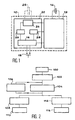
- Figure 1 is a schematic representation of the main elements of a communication device according to the invention.
- Figure 2 is a flowchart illustrating the operation of a device according to the invention.
- FIG. 1 shows a processing unit 10 of a communication device such as a cell phone.
- the processing unit 10 for example with a microprocessor, comprises a first part 12 powered only by an electric battery 14 which forms a main energy source.
- the first part 12 performs the essential functions of communication processing. These telephony-specific functions are known per se and are therefore not described here.
- the first part 12 also constitutes, in the example illustrated, the means for updating the date of commissioning.
- the operation of the first part 12 of the processing unit is suspended after an accidental deactivation, such as in particular a deactivation service resulting from a temporary interruption (micro-interruption) of the main energy source.
- a switch 18, operable by the user, is provided for setting service of the communication device, and in particular of the first part 12.
- the switch is actuated by the user, in particular to put the device back into service after voluntary termination.
- the switch 18 is associated with means 16 for commissioning. These means, the operation of which is specified later, also allow the device to be put back into service, so automatic, after an accidental stop.
- a second part 20 of the processing unit is supplied either by the source main energy 14 during normal operation, either by an energy source auxiliary 22, in the event of the main source being cut off. It essentially includes a clock 24.
- the second part 20 is comparable to a standby system intended for cause an automatic commissioning of the communication device, and in particular of the first part 12, after an accidental cut.
- the second part i.e. the standby system, can also be used to bring the system into service device on a date programmed by the user.
- the clock 24 of the second part which can be distinct from a clock, not shown, of the first part 12, is preferably a low frequency clock of so as to limit its energy consumption.
- a clock with a 32KHz frequency can operate with a current as low as 25 microamps.
- a capacitor 22 represents the sum of the electrical capacities normally existing on a communication device such as a mobile phone. These are, for example, existing filtering capacities for the main energy source.
- the capacitor 22 thus constitutes here the auxiliary energy source.
- a first register 26, connected to the clock 24, contains a representative value of a current date.
- the content of this register is continuously renewed or incremented by the clock, even when the communication device is accidentally turned off service.
- a second register 28 is provided to contain a date of commissioning automatic. It can be seen in the figure that this register is linked to the first part 12 of the processing unit. This is scheduled to periodically renew the content of the second register 28 and bring it to a value which corresponds to a date after the current date contained in the first register 26.
- the two registers 26,28 are connected to the commissioning means 16.
- the means of commissioning 16 are provided with a comparator to compare the content of the two registers 26, 28 and trigger the commissioning of the device if the values turn out to be the same.
- the trigger operated by the means 16 is then equivalent to actuation of the external switch 18 by the user.
- Figure 1 distinguishes the different elements of the device based essentially on their function, in order to simplify the description.
- the different functions for comparing the contents of registers, etc. can be accomplished by simple programming of a microprocessor of the processing unit 10.
- the implementation of the invention is particularly economical for portable telephones which have a delayed commissioning system allowing put them to sleep from a date or time selected by the user.
- These telephones are already equipped with the commissioning means 16, mentioned previously. It then suffices to program the processing unit, and in particular the first part 12, so that the date of commissioning is periodically renewed, when the phone is in use.
- a first step represented by box 100 corresponds to the setting in communication device service. This corresponds to a switch command 18 of Figure 1 by the user. The device is then either in a communication mode effective either in a standby state, awaiting communication. Commissioning initial 100 may also result from delayed commissioning, the date of which will be previously programmed by the user (if this function is available).
- a second step, operated by the processing unit, is represented by the box 102. This corresponds to the activation of clock 24 (figure 1) of the monitoring and loading into the second register 28 (FIG. 1) of a value D corresponding to t + N, where t is the current date and N is an increment of 2 sec, for example.
- a next box 104 corresponds to the normal operation of the processing, and in particular of the first part of this unit.
- Box 104 is parallel with a box 106 which corresponds to a new update of the value contained in the second register.
- the update is carried out periodically by the first part of the processing unit. As long as the first part of the processing unit operating normally, the scheduled commissioning date (and constantly renewed) is not reached by the clock countdown.
- Operation can be stopped by the user, by voluntary deactivation of the monitoring system.
- This command indicated with the reference 108, results in a deactivation 110. In this case no new automatic commissioning is not possible without voluntary user intervention.
- Box 112 corresponds to the exhaustion of the time programmed in the second register. This means that the current date has become identical to the activation date scheduled service. This situation only occurs when the second register stops to be updated, i.e. after an accidental deactivation of the device, which suspends the operation of the first part of the processing unit. This results in a new automatic start-up indicated in box 116.
Landscapes
- Engineering & Computer Science (AREA)
- Computer Networks & Wireless Communication (AREA)
- Signal Processing (AREA)
- Human Computer Interaction (AREA)
- Telephone Function (AREA)
- Mobile Radio Communication Systems (AREA)
- Power Sources (AREA)
- Telephonic Communication Services (AREA)
Abstract
Description
- une source d'énergie principale,
- une unité de traitement alimentée par la source d'énergie principale,
- des moyens de mise en service du dispositif à une date de mise en service programmable.
- une horloge, associée à une source d'énergie auxiliaire, pour fournir une date courante, et
- des moyens de mise à jour automatique et périodique d'une date de mise en service postérieure à la date courante, l'alimentation électrique des moyens de mise à jour étant assurée uniquement à partir de la source d'énergie principale.
- lorsque le dispositif de communication est en service, une date programmable de mise en service automatique est régulièrement mise à jour pour être postérieure à une date courante, et dans lequel,
- lorsque le dispositif de communication est accidentellement mis hors service, une nouvelle mise en service est opérée automatiquement dès qu'une date courante établie par une horloge permanente coïncide avec la date de mise en service précédemment mise à jour.
Claims (8)
- Dispositif de communication à système de maintien en service comportant :caractérisé en ce qu'il comporte en outre :une source d'énergie principale (14),une unité de traitement (10) alimentée par la source d'énergie principale,des moyens (26, 28, 16) de mise en service du dispositif à une date de mise en service programmable,une horloge (24) associée à une source d'énergie auxiliaire (22), pour fournir une date courante, etdes moyens (12) de mise à jour automatique et périodique d'une date de mise en service postérieure à la date courante, l'alimentation électrique des moyens (12) de mise à jour étant assurée uniquement à partir de la source d'énergie principale.
- Dispositif de communication selon la revendication 1, dans lequel l'unité de traitement (10) comporte les moyens de mise à jour automatique de la date de mise en service.
- Dispositif de communication selon la revendication 1, comprenant un registre (28) de date de mise en service, mis à jour par les moyens de mise à jour automatique, à une date D telle que D = t+N, où N est une valeur de temps supérieure ou égale à une périodicité de mise à jour et où t est la date courante.
- Dispositif de communication selon la revendication 1, dans lequel la source d'énergie auxiliaire comporte une capacité électrique.
- Dispositif selon l'une des revendications 1 à 4 caractérisé en ce que le dispositif est un téléphone portable.
- Procédé de maintien en service d'un dispositif de communication suite à une mise hors service accidentelle, dans lequel,lorsque le dispositif de communication est en service, une date programmable de mise en service automatique est régulièrement mise à jour pour être postérieure à une date courante, et dans lequel,lorsque le dispositif de communication est accidentellement mis hors service, une nouvelle mise en service est opérée automatiquement dès qu'une date courante établie par une horloge permanente coïncide avec la date de mise en service précédemment mise à jour.
- Procédé selon la revendication 6, dans lequel la date de mise en service est mise à jour par ajout d'un incrément de temps à la date courante.
- Procédé selon la revendication 7, dans lequel la date de mise en service est mise à jour avec une périodicité plus courte qu'une valeur de l'incrément de temps.
Applications Claiming Priority (2)
| Application Number | Priority Date | Filing Date | Title |
|---|---|---|---|
| FR0004641A FR2807598A1 (fr) | 2000-04-11 | 2000-04-11 | Dispositif de communication portable a systeme de maintien en service automatique et procede de maintien en service d'un tel dispositif |
| FR0004641 | 2000-04-11 |
Publications (2)
| Publication Number | Publication Date |
|---|---|
| EP1146655A1 true EP1146655A1 (fr) | 2001-10-17 |
| EP1146655B1 EP1146655B1 (fr) | 2007-08-22 |
Family
ID=8849131
Family Applications (1)
| Application Number | Title | Priority Date | Filing Date |
|---|---|---|---|
| EP01201201A Expired - Lifetime EP1146655B1 (fr) | 2000-04-11 | 2001-04-02 | Dispositif de communication portable à système de maintien en service automatique et procédé de maintien en service d'un tel dispositif |
Country Status (7)
| Country | Link |
|---|---|
| US (1) | US7392067B2 (fr) |
| EP (1) | EP1146655B1 (fr) |
| JP (1) | JP4900748B2 (fr) |
| KR (1) | KR100742236B1 (fr) |
| CN (1) | CN1193510C (fr) |
| DE (1) | DE60130055T2 (fr) |
| FR (1) | FR2807598A1 (fr) |
Families Citing this family (1)
| Publication number | Priority date | Publication date | Assignee | Title |
|---|---|---|---|---|
| KR100865895B1 (ko) * | 2007-07-12 | 2008-10-29 | 한국과학기술원 | 서브-스레시홀드 전원을 이용한 전력 제어 장치 및 방법 |
Citations (5)
| Publication number | Priority date | Publication date | Assignee | Title |
|---|---|---|---|---|
| US5438695A (en) * | 1989-12-28 | 1995-08-01 | Matsushita Electric Industrial Co., Ltd. | Radio-link continuity keeping equipment in cellular telephone mobile station |
| US5519346A (en) * | 1994-06-22 | 1996-05-21 | Motorola, Inc. | Selective restart circuit for an electronic device |
| WO1996027827A1 (fr) * | 1995-03-06 | 1996-09-12 | Intel Corporation | Systeme informatique automatiquement disponible sur demande |
| WO1998007265A1 (fr) * | 1996-08-12 | 1998-02-19 | Gateway 2000, Inc. | Telephone cellulaire programmable avec activation et desactivation programmees de fonctions |
| US5910944A (en) * | 1997-02-28 | 1999-06-08 | Motorola, Inc. | Radio telephone and method for operating a radiotelephone in slotted paging mode |
Family Cites Families (9)
| Publication number | Priority date | Publication date | Assignee | Title |
|---|---|---|---|---|
| US5036532A (en) * | 1989-08-03 | 1991-07-30 | Motorola, Inc. | Portable telephone with power source/mode change during calls |
| JPH06216827A (ja) * | 1993-01-20 | 1994-08-05 | Mitsubishi Electric Corp | 携帯電話装置 |
| JPH0955781A (ja) * | 1995-08-17 | 1997-02-25 | Sony Corp | 携帯電話機 |
| US5995814A (en) * | 1997-06-13 | 1999-11-30 | Lucent Technologies Inc. | Single-stage dual-band low-noise amplifier for use in a wireless communication system receiver |
| US6178523B1 (en) * | 1998-06-12 | 2001-01-23 | Philips Consumer Communications Lp | Battery-operated device with power failure recovery |
| US6314308B1 (en) * | 1998-07-02 | 2001-11-06 | Snaptrack, Inc. | Method and apparatus for providing reserve power in a cellular telephone |
| KR20000020591A (ko) * | 1998-09-22 | 2000-04-15 | 윤종용 | 전원 자동 온/오프기능을 가지는 휴대폰 및 그 제어방법 |
| US6311081B1 (en) * | 1999-09-15 | 2001-10-30 | Ericsson Inc. | Low power operation in a radiotelephone |
| US6615033B1 (en) * | 2000-01-11 | 2003-09-02 | International Business Machines Corporation | Synchronized-timed-reminded communications for family radios |
-
2000
- 2000-04-11 FR FR0004641A patent/FR2807598A1/fr not_active Withdrawn
-
2001
- 2001-04-02 EP EP01201201A patent/EP1146655B1/fr not_active Expired - Lifetime
- 2001-04-02 DE DE60130055T patent/DE60130055T2/de not_active Expired - Lifetime
- 2001-04-07 CN CNB011196572A patent/CN1193510C/zh not_active Expired - Fee Related
- 2001-04-09 KR KR1020010018594A patent/KR100742236B1/ko not_active Expired - Fee Related
- 2001-04-10 JP JP2001110939A patent/JP4900748B2/ja not_active Expired - Fee Related
- 2001-04-10 US US09/829,794 patent/US7392067B2/en not_active Expired - Lifetime
Patent Citations (5)
| Publication number | Priority date | Publication date | Assignee | Title |
|---|---|---|---|---|
| US5438695A (en) * | 1989-12-28 | 1995-08-01 | Matsushita Electric Industrial Co., Ltd. | Radio-link continuity keeping equipment in cellular telephone mobile station |
| US5519346A (en) * | 1994-06-22 | 1996-05-21 | Motorola, Inc. | Selective restart circuit for an electronic device |
| WO1996027827A1 (fr) * | 1995-03-06 | 1996-09-12 | Intel Corporation | Systeme informatique automatiquement disponible sur demande |
| WO1998007265A1 (fr) * | 1996-08-12 | 1998-02-19 | Gateway 2000, Inc. | Telephone cellulaire programmable avec activation et desactivation programmees de fonctions |
| US5910944A (en) * | 1997-02-28 | 1999-06-08 | Motorola, Inc. | Radio telephone and method for operating a radiotelephone in slotted paging mode |
Also Published As
| Publication number | Publication date |
|---|---|
| CN1318907A (zh) | 2001-10-24 |
| DE60130055D1 (de) | 2007-10-04 |
| DE60130055T2 (de) | 2008-01-03 |
| JP4900748B2 (ja) | 2012-03-21 |
| EP1146655B1 (fr) | 2007-08-22 |
| FR2807598A1 (fr) | 2001-10-12 |
| KR20010098476A (ko) | 2001-11-08 |
| US20010046888A1 (en) | 2001-11-29 |
| KR100742236B1 (ko) | 2007-07-25 |
| US7392067B2 (en) | 2008-06-24 |
| JP2002027103A (ja) | 2002-01-25 |
| CN1193510C (zh) | 2005-03-16 |
Similar Documents
| Publication | Publication Date | Title |
|---|---|---|
| FR2767626A1 (fr) | Terminal radiotelephonique a carte d'identification d'abonne | |
| CA2280598A1 (fr) | Dispositif electronique portable avec circuit de controle de la decharge d'une batterie, et procede associe | |
| FR2918188A1 (fr) | Procede et systeme de gestion de coupures d'alimentation electrique a bord d'un aeronef | |
| EP1146655B1 (fr) | Dispositif de communication portable à système de maintien en service automatique et procédé de maintien en service d'un tel dispositif | |
| EP0880813B1 (fr) | Appareil electronique (notamment piece d'horlogerie) avec un dispositif de charge d'un accumulateur au moyen d'une cellule photovoltaique | |
| EP2395594B1 (fr) | Dispositif et procédé d'alimentation pour système de communication sans fil et ensemble capteur comportant un tel dispositif | |
| EP0571848A1 (fr) | Récepteur d'appel local | |
| EP1071270A1 (fr) | Borne publique d'accès à un réseau informatique | |
| EP0954770B1 (fr) | Montre comportant des moyens de detection et de sauvegarde en cas d'insuffisance de la source d'alimentation | |
| FR2540646A1 (fr) | Horloge electronique fonctionnant sur le secteur, notamment horloge a contacts a reserve de marche | |
| EP0009606B1 (fr) | Dispositif de commande de charge d'une batterie d'accumulateurs | |
| EP3672024A1 (fr) | Procédé et dispositif de commande de recharge et de décharge de batteries d'un ensemble desdites batteries | |
| EP0080396B1 (fr) | Circuit téléphonique, géré par microprocesseur à circuit intégré de transmission 2 fils-4 fils, et alimentation de sauvegarde par courant de ligne | |
| EP0428448B1 (fr) | Dispositif de programmation horaire et de renvoi automatique des appels d'une ligne téléphonique d'un abonné | |
| EP3469452A1 (fr) | Gestion optimisée de l'alimentation d'un microcontrôleur | |
| FR2633837A1 (fr) | Circuit de charge-decharge pour le condensateur d'un defibrillateur cardiaque | |
| WO2026068476A1 (fr) | Systeme de gestion d'un pack batterie pour l'alimentation d'un actionneur en veille | |
| FR3039627A1 (fr) | Systeme d'eclairage de secours | |
| FR2801982A1 (fr) | Dispositif de controle d'une batterie d'accumulateurs et son procede associe | |
| EP3319200A1 (fr) | Procédé et système de contrôle de charge d'une batterie d'un équipement électrique | |
| FR3138013A1 (fr) | Horloge à super-condensateur | |
| JP2002267528A (ja) | 感震装置 | |
| FR2939597A1 (fr) | Dispositif d'eclairage public muni de moyens de controle. | |
| FR2793092A1 (fr) | Procede de gestion de donnees horodatrices dans une terminaison numerique de reseau a l'occasion d'une reinitialisation de la terminaison | |
| FR2812468A1 (fr) | Batterie et chargeur de telephone a determination de parametres de charge fiabilisee |
Legal Events
| Date | Code | Title | Description |
|---|---|---|---|
| PUAI | Public reference made under article 153(3) epc to a published international application that has entered the european phase |
Free format text: ORIGINAL CODE: 0009012 |
|
| AK | Designated contracting states |
Kind code of ref document: A1 Designated state(s): DE FR GB IT Kind code of ref document: A1 Designated state(s): AT BE CH CY DE DK ES FI FR GB GR IE IT LI LU MC NL PT SE TR |
|
| AX | Request for extension of the european patent |
Free format text: AL;LT;LV;MK;RO;SI |
|
| 17P | Request for examination filed |
Effective date: 20020417 |
|
| AKX | Designation fees paid |
Free format text: DE FR GB IT |
|
| GRAP | Despatch of communication of intention to grant a patent |
Free format text: ORIGINAL CODE: EPIDOSNIGR1 |
|
| GRAS | Grant fee paid |
Free format text: ORIGINAL CODE: EPIDOSNIGR3 |
|
| GRAA | (expected) grant |
Free format text: ORIGINAL CODE: 0009210 |
|
| RAP1 | Party data changed (applicant data changed or rights of an application transferred) |
Owner name: NXP B.V. |
|
| AK | Designated contracting states |
Kind code of ref document: B1 Designated state(s): DE FR GB IT |
|
| REG | Reference to a national code |
Ref country code: GB Ref legal event code: FG4D Free format text: NOT ENGLISH |
|
| REF | Corresponds to: |
Ref document number: 60130055 Country of ref document: DE Date of ref document: 20071004 Kind code of ref document: P |
|
| GBT | Gb: translation of ep patent filed (gb section 77(6)(a)/1977) |
Effective date: 20071105 |
|
| PLBE | No opposition filed within time limit |
Free format text: ORIGINAL CODE: 0009261 |
|
| STAA | Information on the status of an ep patent application or granted ep patent |
Free format text: STATUS: NO OPPOSITION FILED WITHIN TIME LIMIT |
|
| 26N | No opposition filed |
Effective date: 20080526 |
|
| PG25 | Lapsed in a contracting state [announced via postgrant information from national office to epo] |
Ref country code: IT Free format text: LAPSE BECAUSE OF NON-PAYMENT OF DUE FEES Effective date: 20080430 |
|
| PGFP | Annual fee paid to national office [announced via postgrant information from national office to epo] |
Ref country code: GB Payment date: 20130326 Year of fee payment: 13 |
|
| PGFP | Annual fee paid to national office [announced via postgrant information from national office to epo] |
Ref country code: DE Payment date: 20130322 Year of fee payment: 13 |
|
| PGFP | Annual fee paid to national office [announced via postgrant information from national office to epo] |
Ref country code: FR Payment date: 20130920 Year of fee payment: 13 |
|
| REG | Reference to a national code |
Ref country code: DE Ref legal event code: R119 Ref document number: 60130055 Country of ref document: DE |
|
| GBPC | Gb: european patent ceased through non-payment of renewal fee |
Effective date: 20140402 |
|
| REG | Reference to a national code |
Ref country code: FR Ref legal event code: ST Effective date: 20141231 |
|
| REG | Reference to a national code |
Ref country code: DE Ref legal event code: R119 Ref document number: 60130055 Country of ref document: DE Effective date: 20141101 |
|
| PG25 | Lapsed in a contracting state [announced via postgrant information from national office to epo] |
Ref country code: GB Free format text: LAPSE BECAUSE OF NON-PAYMENT OF DUE FEES Effective date: 20140402 Ref country code: DE Free format text: LAPSE BECAUSE OF NON-PAYMENT OF DUE FEES Effective date: 20141101 |
|
| PG25 | Lapsed in a contracting state [announced via postgrant information from national office to epo] |
Ref country code: FR Free format text: LAPSE BECAUSE OF NON-PAYMENT OF DUE FEES Effective date: 20140430 |