EP1146521B1 - Dispositif de mesure du temps de chute de barres de commande à l'intérieur du coeur d'un réacteur nucléaire - Google Patents
Dispositif de mesure du temps de chute de barres de commande à l'intérieur du coeur d'un réacteur nucléaire Download PDFInfo
- Publication number
- EP1146521B1 EP1146521B1 EP01400180A EP01400180A EP1146521B1 EP 1146521 B1 EP1146521 B1 EP 1146521B1 EP 01400180 A EP01400180 A EP 01400180A EP 01400180 A EP01400180 A EP 01400180A EP 1146521 B1 EP1146521 B1 EP 1146521B1
- Authority
- EP
- European Patent Office
- Prior art keywords
- control
- nuclear reactor
- rods
- control rods
- measuring
- Prior art date
- Legal status (The legal status is an assumption and is not a legal conclusion. Google has not performed a legal analysis and makes no representation as to the accuracy of the status listed.)
- Expired - Lifetime
Links
- 238000009434 installation Methods 0.000 title 1
- 238000004804 winding Methods 0.000 claims description 66
- 238000005259 measurement Methods 0.000 claims description 55
- 230000002745 absorbent Effects 0.000 claims description 22
- 239000002250 absorbent Substances 0.000 claims description 22
- 230000007246 mechanism Effects 0.000 claims description 18
- 238000006073 displacement reaction Methods 0.000 claims description 15
- 238000000429 assembly Methods 0.000 claims description 14
- 230000000712 assembly Effects 0.000 claims description 13
- 239000000446 fuel Substances 0.000 claims description 12
- 230000004323 axial length Effects 0.000 claims description 4
- 238000003780 insertion Methods 0.000 claims description 4
- 230000037431 insertion Effects 0.000 claims description 4
- 238000009413 insulation Methods 0.000 claims 3
- 238000002955 isolation Methods 0.000 description 12
- 230000009257 reactivity Effects 0.000 description 7
- 230000006870 function Effects 0.000 description 6
- XLYOFNOQVPJJNP-UHFFFAOYSA-N water Substances O XLYOFNOQVPJJNP-UHFFFAOYSA-N 0.000 description 6
- 238000012360 testing method Methods 0.000 description 5
- 238000012545 processing Methods 0.000 description 3
- 230000001681 protective effect Effects 0.000 description 3
- 230000008901 benefit Effects 0.000 description 2
- 238000010586 diagram Methods 0.000 description 2
- 230000000694 effects Effects 0.000 description 2
- 230000005484 gravity Effects 0.000 description 2
- 238000000034 method Methods 0.000 description 2
- 230000001133 acceleration Effects 0.000 description 1
- 230000008859 change Effects 0.000 description 1
- 230000008878 coupling Effects 0.000 description 1
- 238000010168 coupling process Methods 0.000 description 1
- 238000005859 coupling reaction Methods 0.000 description 1
- 230000007423 decrease Effects 0.000 description 1
- 230000003247 decreasing effect Effects 0.000 description 1
- 208000001321 ectrodactyly, ectodermal dysplasia, and cleft lip-palate syndrome 1 Diseases 0.000 description 1
- 238000012423 maintenance Methods 0.000 description 1
- 230000014759 maintenance of location Effects 0.000 description 1
- 230000008569 process Effects 0.000 description 1
- 230000004043 responsiveness Effects 0.000 description 1
- 230000006641 stabilisation Effects 0.000 description 1
- 238000011105 stabilization Methods 0.000 description 1
- 239000000725 suspension Substances 0.000 description 1
- 238000012546 transfer Methods 0.000 description 1
Images



Classifications
-
- G—PHYSICS
- G21—NUCLEAR PHYSICS; NUCLEAR ENGINEERING
- G21C—NUCLEAR REACTORS
- G21C17/00—Monitoring; Testing ; Maintaining
-
- Y—GENERAL TAGGING OF NEW TECHNOLOGICAL DEVELOPMENTS; GENERAL TAGGING OF CROSS-SECTIONAL TECHNOLOGIES SPANNING OVER SEVERAL SECTIONS OF THE IPC; TECHNICAL SUBJECTS COVERED BY FORMER USPC CROSS-REFERENCE ART COLLECTIONS [XRACs] AND DIGESTS
- Y02—TECHNOLOGIES OR APPLICATIONS FOR MITIGATION OR ADAPTATION AGAINST CLIMATE CHANGE
- Y02E—REDUCTION OF GREENHOUSE GAS [GHG] EMISSIONS, RELATED TO ENERGY GENERATION, TRANSMISSION OR DISTRIBUTION
- Y02E30/00—Energy generation of nuclear origin
- Y02E30/30—Nuclear fission reactors
Definitions
- the invention relates to a device for measuring the fall time of control rods inside the core of a nuclear reactor and in particular inside the heart of a nuclear reactor cooled by water under pressure.
- Nuclear reactors such as nuclear reactors cooled by pressurized water has a tank closed at its upper part by a lid, enclosing the reactor core which consists of fuel assemblies, of a general prismatic shape, placed in adjacent arrangements, with their vertical axes.
- Each of the fuel assemblies has a set of vertical guide tubes in each of which one can move a pencil of an absorbent cluster of a control bar of the reactivity of the heart nuclear reactor.
- control rods that are moved in a number of assemblages distributed along the cross-section of the heart.
- Each of the control bars has a control cluster constituted by absorbent pencils connected in parallel to each other, to a fixing and suspension device called pommel which is connected to a control rod made in fluted form, in order to move the control bars step by step according to the height from the heart of the nuclear reactor, to adjust the reactivity.
- Command bars are moved according to the height of the heart by mechanisms that are attached to vertical tubular enclosures arranged above the lid of the tank.
- the control rods that are moved in a coaxial arrangement inside the tubular enclosures cooperate, through their grooves, with ratchets mechanisms for moving the control bar.
- the control rods of the nuclear reactor also have a safety function, since they must make it possible to carry out emergency stops of the nuclear reactor, by pulling the control rods into position maximum insertion inside the nuclear reactor core.
- the mechanism of the control rods achieves a release of the control rod, so that the rod and the control rod can fall back under the effect of gravity inside the reactor core nuclear.
- the displacement of the control rod in the axial direction inside the tubular enclosure produces a voltage induced inside the primary winding, this voltage induced varying according to the speed of movement of the stem of control and length of the section of the control rod inside primary winding.
- the measurements are carried out successively on subgroups of control rods distributed in the nuclear reactor core.
- the measurements are carried out successively for subgroups of four control rods that are placed in four parts of the heart called quadrants separated from each other by two 90 ° symmetry planes passing through the core axis of the nuclear reactor.
- quadrants separated from each other by two 90 ° symmetry planes passing through the core axis of the nuclear reactor.
- the object of the invention is therefore to propose a device for measuring the drop time of control rods inside the core of a reactor nuclear reactor having a vessel closed at its upper part by a lid and enclosing the reactor core consisting of assemblies of fuel in adjacent vertical arrangements and incorporating vertical guide tubes for absorbent rods of a plurality of control rods each consisting of a cluster of absorbent rods and a control rod connected at one of its ends to the control cluster, a plurality of tubular speakers arranged vertically above the lid of the tank each having a mechanism moving a control bar through its movable vertical control rod in the axial direction of the tubular enclosure and release the control bar to ensure its fall in maximum insertion position in the nuclear reactor core, at least a measurement electric winding surrounding each tubular enclosure, substantially along its entire axial length, connected to a sensing cable of an electric voltage across the winding, the control rods being grouped into subsets and each electrical winding of each control rods of a subassembly being connected by its cable to a unit for
- FIG. 1 is a schematic view in vertical section of a tank a pressurized water nuclear reactor and means for adjusting the reactivity of the nuclear reactor core.
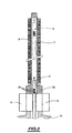
- FIG. 2 is a view in axial section of a tubular enclosure and mechanisms for moving a control rod inside the enclosure tubular.
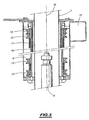
- FIG. 3 is an enlarged partial sectional view of a portion of the chamber shown in FIG. 2 and its position measuring coils a command bar.
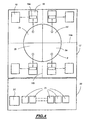
- FIG. 4 is a schematic view of an assembly according to the prior art processing of the control rod position measurements of a nuclear reactor, for reactor protection and displacement control control rods.
- FIG. 5 is a schematic view, similar to the view of FIG. 4, showing a device for measuring the fall time of the control rods according to the invention.
- FIG. 6 is a detailed view of the connection means of a cable measuring device according to the invention.
- FIG. 7 is a diagram giving the voltage induced in a winding primary measurement of a tubular enclosure of a control bar, as a function of time, during the fall of a control bar.
- FIG. 1 shows the tank 1 of a nuclear reactor at pressurized water which encloses the core 2 of the reactor and which is closed at its upper part by a lid 1a of substantially hemispherical shape.
- the core 2 of the nuclear reactor consists of assemblies fuel placed vertically in adjacent comprise means for guiding absorbent rods of bars of control which is made to move inside the core 2 of the reactor nuclear in the vertical direction, to adjust the reactivity of the heart.
- FIG. 1 schematically shows two sets 3 guide of absorbent rods of two assemblies of the nuclear reactor core inside each of which one moves a bunch of absorbent rods 4 conventionally represented under form of a massive set.
- the cluster of absorbent rods 4 is constituted by a set of parallel rods and the guide assembly 3 is constituted by a set of guide tubes of the fuel assembly in which we move the cluster of absorbent pencils, each of the absorbent pencils the cluster being guided inside the fuel assembly by a guide tube.
- Each of the bunches of absorbent pencils 4 is connected to its part greater than a control rod 6 arranged in the axial extension of the cluster 4.
- the set constituted by the cluster of absorbent pencils and the stem control 6 constitutes a control bar 5 of the responsiveness in the heart of the nuclear reactor.
- Figure 1 there is shown one of the bunches of absorbent rods 4 in the low position, fully inserted into the heart and the second cluster of absorbent pencils 4 in the upper position, totally extracted from heart 2.
- control rods 6 are fluted rods, the groove of which defines teeth over the entire length of the control rod.
- control rods 6 of the control rods 5 move, between the fully extracted upper position of the control bar and the low position fully inserted, inside fixed 7 tubular enclosures in the vertical direction above the lid 1a of the tank, vertically of the cluster guide tube and in the upper part of the tank of the nuclear reactor.
- Each of the tubular enclosures 7 comprises a mechanism 8 of moving the corresponding control bar 5, via of its fluted control rod 6.
- Mechanisms 8 are ratchet mechanisms that cooperate with the toothing of the fluted control rod 6 to move step by step the control rod inside the tubular enclosure 7 and the cluster of command 4 inside the core 2 of the nuclear reactor to achieve the adjustment of the reactivity of the heart.
- the mechanisms 8 include pawls of movement and retaining ratchets of the control rods via the rods control, the opening of the retaining pawls allowing a release of the control rod and the control bar from a position high, the control bar can then fall back into the insertion position maximum in the nuclear reactor core under the effect of gravity.
- tubular enclosures 7 for moving control rods 6 of the control rods 5 are arranged, on a substantial part the length of the tubular enclosure in the axial direction, above mechanisms 8, means 9 for measuring the position of the control rod inside the tubular enclosure 7 and therefore the cluster absorbent 4 of the control rod 5, inside the reactor core nuclear.
- FIG. 2 shows a tubular enclosure 7 in which moves a fluted control rod 6 at the lower end of which (not shown) is attached a control cluster.
- the tubular enclosure 7 is fixed in the axial extension of an element tubular 7a fixed on the lid 1a of the tank and ensuring the crossing of the control rod 6, on which are fixed the movement mechanisms 8 of the control bar, via the fluted rod 6.
- the pawls of restraint and displacement mechanisms 8 of the control bar come into engagement, inside the tubular part 7a of the enclosure 7, with the toothing 6a of the fluted control rod 6.
- the rod 6 is shown in solid lines in its position. low corresponding to the fully inserted position of the cluster of absorbent rods in the nuclear reactor core and in broken lines, the control rod 6 in the upper position inside the upper part of the tubular enclosure 7.
- the upper part of the tubular enclosure 7 makes it possible to move of the control rod 6 along a length equal to the height total heart, that is to say on a length of the order of four to five meters.
- the device 9 for measuring the position of the control bar is arranged around the upper part of the tubular enclosure 7 and substantially the entire length of this upper part, above the mechanisms 8.
- the device 9 for measuring the position control rods are arranged around the tubular enclosure 7 on which it is fixed by means of upper and lower flanges.
- the measuring device 9 is disposed inside a shape envelope tubular structure delimited by two coaxial cylindrical shells in a coaxial arrangement with respect to the tubular enclosure 7 in which the rod command 6 of the command bar moves in the direction axial 10.
- the measuring device 9 has the general shape of a transformer differential having a primary winding 11 extending substantially over the entire length of the measuring device, that is to say substantially over the entire axial length of the tubular enclosure and the coils secondary 12 distributed in the axial direction 10 of the measuring device, with constant spacing.
- the primary winding 11 and the secondary windings 12 as well as auxiliary end windings 13, located at the axial ends of the device 9, are arranged in annular cavities of a support 14 placed in a coaxial arrangement with respect to the tubular enclosure 7.
- the different windings are connected to power supply lines and measurement, via a connection box 15.
- the primary winding 11 is supplied with alternating current at a frequency 50 Hz, the voltage in the winding can be further captured via a sensing cable connected to the connection device 15.
- Each of the secondary windings 12 and the auxiliary windings 13 is also connected to a cable for sensing the voltage across the terminals of winding which is connected inside the connection device 15.
- the measurement of the voltages induced by the primary winding in each secondary windings or in secondary windings placed in series allows to determine the position of the control rod 6 inside of the tubular enclosure 7 and therefore of the control bar in the nuclear reactor core, the presence of the control rod 6 opposite a secondary winding 12 modifying the reluctance of the secondary winding and therefore the coupling of the primary winding and the secondary winding.
- FIG. 4 shows the section of the core 2 of a reactor pressurized water reactor having four quadrants 2a, 2b, 2c, 2d, separated from each other by two vertical planes of symmetry of traces 16a and 16b in Figure 4 perpendicular to each other and passing through the axis of heart 2.
- the displacement of eighteen absorbent clusters is achieved of eighteen control rods of the reactivity of the heart, the assemblies of fuel in which the absorbent bunches are moved being distributed according to the surface of the quadrants.
- the nuclear reactor is therefore piloted from seventy-three clusters divided into three subsets of eighteen clusters and a subset of nineteen clusters.
- Each subset of control rods and absorbent clusters has its own means of collecting position measurements control rods of the subset and processing these measurements for the protection of the nuclear reactor, during its operation.
- All means of collecting position measurements and means of protection of the heart is disposed in protective rooms 17 placed around the nuclear reactor vessel containing the core 2.
- the protective rooms 17 contain, for each of the subassemblies of control bars associated with a quadrant of the core 2, means 18 of collecting measurements made on the eighteen or nineteen control bars of the subassembly.
- IPB cabinets The means for collecting 18 measurements of the position of the bars of order a subset are called IPB cabinets, these cabinets containing bar position instrumentation sensors (abbreviated IPB).
- IPB bar position instrumentation sensors
- the measuring means of each of the control rods are connected by measuring cables to the corresponding IPB cabinet in which measurement sensors 18a transfer the measurement signals to a data acquisition and processing unit for the protection of the nuclear reactor 19 called UATP cabinet.
- the signals transmitted to the IPB cabinet are the signals of voltage of the primary windings of the position measuring means of each tubular enclosures for moving a control rod a command bar.
- the position measurements made on the control rods are also used within a displacement control room 20 control rods in which are arranged especially nineteen cabinets 21 called EEC1 cabinets ... EEC19 cabinets that contain a electronic control unit for moving the bars of ordered.
- These sets are units of the control system of the displacements of the control rods which deliver currents to the actuators mechanisms for moving the control rods, according to orders received by the pilotage units.
- a driving unit power groups and a steering unit of the stopping and the temperature in the nuclear reactor core.
- FIG. 5 shows a measuring device according to the invention to overcome the disadvantages of measuring operations performed according to the prior art.
- FIG. which has been shown the protective rooms 17 and the control rooms 20 of the displacement of the control rods, the corresponding elements in Figures 4 and 5 being designated by the same references.
- the measuring device comprises, at the level of each of the IPB cabinets of each of the subsets of command receiving the measurement signals from the control rods, a set of connection means 23 each made in the form of a receiving interface box, by measuring cables of each of the bars control of the subset, the measurement signals and in particular the voltage signals of the primary windings of the measuring means positions of the control rods.
- the interface boxes 23 permanently connected to the cables measurement of the control bars of the subassembly allow to extract, without making a connection, the voltage signals of the windings primary means of measuring position of the control rods for make measurements of the fall time of the control rods in their together.
- Each of the interface boxes 23 of an IPB cabinet 18 of a subassembly of control rods is connected, via a cabinet 24, to a system 25 for acquiring the measurement signals of voltage of the primary windings in real time, arranged in the room of movement control 20 of the control rods.
- the system for real-time acquisition of the signals measuring device can simultaneously receive the voltage signals from the set of primary windings of the displacement measuring means of all the control rods, for example during a test for the measurement of the fall time of the control rods.
- Each IPB cabinet 18 therefore comprises an interface box 23 for each of the sensing and measurement cables from each of the means for measuring the displacement of a control bar.
- Each interface box 23 is connected to the acquisition system 25 by through an isolation cabinet 24.
- FIG. 6 shows the frame of the IPB cabinet 18 to which is connected, via the interface boxes 23, each of the cables of measure 29 associated with measuring means of moving a bar of ordered.
- a cable 30 makes it possible to take the voltage signals coming from the primary windings measuring means for transmitting them to the system acquisition in real time, through an isolation box 24.
- Each of the interface boxes 23 includes an attenuator allowing to adapt the level of the signal transmitted to the electronics carrying out the isolation galvanic signals in the isolation cabinet 24 and protect the primary winding circuit against short circuit risks.
- Galvanic isolation cabinet 24 contains two isolation cards each with ten channels and supports an isolation of 500 volts effective, the output voltage being 10 volts.
- Isolation boxes 24, associated with each of the subassemblies of control rods, make it possible to separate the protection functions and control by avoiding any electrical interference from components that are not classified for the safety of the nuclear reactor. There is no risk of disrupting the operation of the units 19 of the protection of the nuclear reactor from the measurements taken by the interface boxes 23, in the cabinets IPB 18.
- the IPB interface incorporating the measuring device according to the invention comprises a total of seventy-three equipped interface boxes attenuators, eight electronic isolation cards and four cabinets isolation.
- a second part of the measuring device according to the invention is placed inside the control room 20 for moving the bars of ordered.
- the measuring device comprises, within the local RGL, the system 25 for real-time acquisition of measurement signals which is connected on the one hand, through four isolation boxes 24, the four IPB 18 cabinets and secondly, inside the room RGL 20, to each of the EEC cabinets, that is to say electronic assemblies of control of cluster movements.
- the acquisition system 25 receives an automatic shutdown signal from the reactor clusters that is taken from a free contact of the reactor control unit nuclear.
- Galvanic isolation of 500 volts is achieved by standard modules inserted in a data acquisition system chassis 25, to effectively isolate the unit acquisition system control of movement of the clusters of the local RGL.
- All the measurement signals of the primary windings are grouped together at the level of the real-time acquisition system 25 which provides, for each control rods, at the time of the fall of the control bar, a curve giving the voltage induced in the primary winding in function of time, this curve making it possible to determine the duration of the signal of tension and to deduce the time of fall of the control bar.
- the data is processed by a microcomputer 26 which allows determine the fall time of the control rods and put them in memory.
- Input data and data provided by the microcomputer 26 relating to the falling time can be printed on a printer 27.
- the microcomputer 26 and the printer 27 therefore constitute means to view and print the fall time results control rods.
- FIG. 7 there is shown in a diagram giving the voltage as a function of time, the voltage curve induced in a winding of a tubular chamber of a control bar, during the drop of the control bar.
- the displacement of the control rod inside the enclosure tubular and inside the primary winding produces a dynamic change the reluctance of the winding and therefore a voltage induced at the terminals primary winding.
- the times t0, t1, t2 are plotted on the abscissa axis. and t3.
- the time t0 corresponds to the time origin for the measurement of time of fall. This time t0 can be determined in different ways. All first, the time t0 can be determined from the emergency stop signal 28 nuclear reactor that is transmitted to the acquisition system 25.
- the time t0 can also be determined from the signals of current 32 which are transmitted by the cabinets 21 of the local RGL system 25. These signals 32 correspond to the supply current fixed grapples of the mechanisms of movement of the control rods ensuring the retention of rods and control rods. cancellation of the fixed grapple feed current reflects the moment of release of the control bar. Finally, the origin of the fall of the command bar can also be determined from the pace of the voltage curve induced 31 as a function of time, purely graphically.
- the voltage induced decreases to return to a level substantially equal to the level of departure, with some instability.
- the fall is over, when the induced voltage returns for the first time to the starting level.
- This phase during which the induced voltage is decreasing translates the output of the control rod of the tubular enclosure and the winding primary.
- the fall time is determined by adding the times T4, T5 and T6.
- the primary winding is usually powered by alternating current at a frequency of 50 Hz and at a voltage of 50 to 70 V.
- the induced voltage is a signal with very low frequency (# 10 Hz) and amplitude of some volts following the initial position of the control bar at the moment of his release.
- the primary winding In the case where the primary winding is not powered, it is directly the voltage induced across the primary winding.
- the device according to the invention makes it possible to carry out precise measurements the time of fall of the control rods with a very small number measurements, for example one or two measurements, the signals relating to the set bars that can be saved in one operation then processed after storing.
- the process according to the invention has the advantage of avoiding any operation connection and disconnection of measurement lines, before and after fall time measurements.
- the device according to the invention also has the advantage of ability to perform measurements during operation of the nuclear reactor and in the case of the accidental fall of a control bar, the induced voltage signal is then recorded automatically by the system for acquiring signals in real time.
- control rods consisting of control clusters that are moved vertically into the heart of a nuclear reactor via control rods.
Landscapes
- Physics & Mathematics (AREA)
- Engineering & Computer Science (AREA)
- Plasma & Fusion (AREA)
- General Engineering & Computer Science (AREA)
- High Energy & Nuclear Physics (AREA)
- Monitoring And Testing Of Nuclear Reactors (AREA)
Description
- un module d'acquisition de signaux de mesure en temps réel,
- des moyens de connexion des câbles de captage de chacun des bobinages électriques de mesure au module d'acquisition pour la réception de signaux de mesure de tension aux bornes de chacun des bobinages électriques, et
- des moyens d'exploitation des signaux de tension reliés au module d'acquisition pour mesurer le temps de chute des barres de commande du réacteur nucléaire.
Claims (8)
- Dispositif de mesure du temps de chute d'une barre de commande à l'intérieur du coeur d'un réacteur nucléaire comportant une cuve (1) fermée à sa partie supérieure par un couvercle (1a) et renfermant le coeur (2) du réacteur constitué par des assemblages de combustible dans des dispositions adjacentes verticales et comportant des tubes de guidage verticaux (3) pour des crayons absorbants d'une pluralité de barres de commande (5) constituées chacune par une grappe de crayons absorbants (4) et une tige de commande (6) reliée, à l'une de ses extrémités, à la grappe de commande (4), une pluralité d'enceintes tubulaires (7) disposées verticalement au-dessus du couvercle (1a) de la cuve (1) comportant chacune un mécanisme de déplacement (8) d'une barre de commande par l'intermédiaire de sa tige de commande (6) verticale, dans la direction verticale axiale de l'enceinte tubulaire (7), et de libération de la barre de commande (5) pour assurer sa chute en position d'insertion maximale dans le coeur (2) du réacteur nucléaire, au moins un bobinage électrique (9) de mesure entourant chaque enceinte tubulaire (7), sensiblement suivant toute sa longueur axiale, relié à un câble de captage (29) d'une tension électrique aux bornes du bobinage, les barres de commande (5) étant regroupées en sous-ensembles et chaque bobinage électrique (9) de chacune des barres d'un sous-ensemble étant relié par son câble de captage à une unité de recueil (18) des signaux de mesure, caractérisé par le fait qu'il comporte de plus :un module (25) d'acquisition de signaux de mesure en temps réel,des moyens (23, 30, 24) de connexion de chacun des câbles de captage (29) de chacun des bobinages électriques de mesure (9) au module d'acquisition (25) pour la réception de signaux de mesure de tension aux bornes de chacun des bobinages électriques (9), etdes moyens d'exploitation (26, 27) des signaux de tension reliés au module d'acquisition (25) pour mesurer le temps de chute des barres de commande (5) du réacteur nucléaire.
- Dispositif suivant la revendication 1, caractérisé par le fait que chaque unité de recueil des signaux de mesure (18) est constituée par une armoire renfermant une pluralité de capteurs (18a) d'instrumentation de position des barres de commande du réacteur et que les moyens de connexion (23, 24) comportent un boítier d'interface (23) pour chacun des câbles de mesure de chacun des bobinages électriques (9), disposé dans l'armoire des capteurs d'instrumentation de position des barres (18) auquel est relié un câble (30) de prélèvement d'une tension induite aux bornes du bobinage électrique (9) disposé autour de l'enceinte annulaire (7) de la barre de commande (5).
- Dispositif suivant la revendication 2, caractérisé par le fait que les moyens de connexion comportent au moins un boítier d'isolement (24) auquel sont reliés les câbles (30) de prélèvement de la tension induite aux bornes du bobinage électrique (9) d'une partie au moins des barres de commande (5), le module d'acquisition de signaux (25) étant relié à l'au moins un boítier d'isolement (24).
- Dispositif suivant l'une quelconque des revendications 2 et 3, caractérisé par le fait qu'il comporte quatre armoires (18) renfermant des capteurs (18a) d'instrumentation de position des barres de commande du réacteur nucléaire associées chacune à une partie du coeur (2) du réacteur nucléaire ayant une section en forme de quadrant, le coeur du réacteur nucléaire comportant quatre quadrants (2a, 2b, 2c, 2d) délimités par deux plans de symétrie perpendiculaires entre eux passant par l'axe vertical (2) du coeur du réacteur nucléaire, les bobinages électriques de mesure (9) de chacune des barres de commande dans une partie du coeur (2) du réacteur nucléaire étant reliés à l'une des quatre armoires (18) renfermant des capteurs (18a) d'instrumentation de position des barres de commande et les boítiers d'interface (23) reliés aux câbles de captage (29) des bobinages électriques (9) des barres de commande (5) étant disposés dans les armoires (18) renfermant les capteurs (18a) d'instrumentation de position des barres.
- Dispositif suivant la revendication 4, caractérisé par le fait qu'il comporte quatre coffrets d'isolement galvanique (24) par l'intermédiaire de chacun desquels les coffrets d'interface (23) de prélèvement des signaux de mesure des barres de commande dans une partie du coeur (2) sont reliés au module d'acquisition de signaux (25).
- Dispositif suivant l'une quelconque des revendications 1 à 5, caractérisé par le fait que les moyens de connexion (23, 30, 24) de chacun des câbles de captage (29) de chacun des bobinages électriques de mesure (9) sont disposés à l'intérieur de locaux de protection (17) du réacteur nucléaire et que le module d'acquisition de signaux de mesure (25) et les moyens d'exploitation des signaux (26, 27) sont disposés dans un local (20) de commande de déplacement des barres de commande (5).
- Dispositif suivant l'une quelconque des revendications 1 à 6, caractérisé par le fait que les moyens d'exploitation des signaux de tension reliés au module d'acquisition (25) comportent un micro-ordinateur (26) de calcul du temps de chute des barres de commande (5).
- Dispositif suivant l'une quelconque des revendications 1 à 7, caractérisé par le fait que les bobinages électriques de mesure (9) sont constitués par des bobinages primaires (11) de dispositifs de mesure de déplacement des barres de commande (5).
Applications Claiming Priority (2)
| Application Number | Priority Date | Filing Date | Title |
|---|---|---|---|
| FR0004868 | 2000-04-14 | ||
| FR0004868A FR2807866B1 (fr) | 2000-04-14 | 2000-04-14 | Dispositif de mesure du temps de chute de barres de commande a l'interieur du coeur d'un reacteur nucleaire |
Publications (2)
| Publication Number | Publication Date |
|---|---|
| EP1146521A1 EP1146521A1 (fr) | 2001-10-17 |
| EP1146521B1 true EP1146521B1 (fr) | 2003-07-09 |
Family
ID=8849285
Family Applications (1)
| Application Number | Title | Priority Date | Filing Date |
|---|---|---|---|
| EP01400180A Expired - Lifetime EP1146521B1 (fr) | 2000-04-14 | 2001-01-22 | Dispositif de mesure du temps de chute de barres de commande à l'intérieur du coeur d'un réacteur nucléaire |
Country Status (4)
| Country | Link |
|---|---|
| US (1) | US6606367B2 (fr) |
| EP (1) | EP1146521B1 (fr) |
| CN (1) | CN1165052C (fr) |
| FR (1) | FR2807866B1 (fr) |
Families Citing this family (6)
| Publication number | Priority date | Publication date | Assignee | Title |
|---|---|---|---|---|
| US7505545B2 (en) * | 2004-06-24 | 2009-03-17 | Korea Electro Technology Research Institute | Method for recognizing step movement sequence of control rod drive mechanism of nuclear reactor |
| US8903033B2 (en) * | 2008-01-09 | 2014-12-02 | Analysis and Measurement Service Corporation | High resolution digital rod position indication system for nuclear power plants |
| JP5497426B2 (ja) * | 2009-12-28 | 2014-05-21 | 日立Geニュークリア・エナジー株式会社 | 軽水炉の炉心及び燃料集合体 |
| CN101964215B (zh) * | 2010-08-03 | 2013-03-13 | 中广核工程有限公司 | 一种核电站机组功率控制系统 |
| CN112185596B (zh) * | 2020-09-30 | 2022-02-11 | 中国核动力研究设计院 | 基于核电站测量线圈的落棒时间测量方法、介质和系统 |
| CN112599265B (zh) * | 2020-12-05 | 2023-02-10 | 核电运行研究(上海)有限公司 | 一种与棒位测量设备集成的控制棒落棒时间测量方法 |
Family Cites Families (14)
| Publication number | Priority date | Publication date | Assignee | Title |
|---|---|---|---|---|
| DE250201C (fr) | ||||
| US4155116A (en) * | 1978-01-04 | 1979-05-15 | The Bendix Corporation | Digital control system including built in test equipment |
| US4314881A (en) * | 1980-03-18 | 1982-02-09 | The United States Of America As Represented By The United States Department Of Energy | Reactor control rod timing system |
| US4668465A (en) * | 1984-10-26 | 1987-05-26 | Westinghouse Electric Corp. | Method and apparatus for remotely monitoring a process carried out in a containment structure |
| DD250201B5 (de) * | 1986-06-19 | 1993-12-09 | Energiewerke Nord Gmbh | Verfahren zum bewerten der funktionsweise von regelelementen |
| US4896101A (en) * | 1986-12-03 | 1990-01-23 | Cobb Harold R W | Method for monitoring, recording, and evaluating valve operating trends |
| KR890007306A (ko) * | 1987-10-30 | 1989-06-19 | 제트.엘.더머 | 온라인 밸브 진단 감시 시스템 |
| FR2632443A1 (en) * | 1988-06-01 | 1989-12-08 | Mitsubishi Heavy Ind Ltd | System for supervising the operating conditions of a driving mechanism of a control rod |
| US5006301A (en) * | 1989-03-22 | 1991-04-09 | Joyner Engineers And Trainers, Inc. | Method and apparatus for control rod drop monitoring |
| US5956381A (en) * | 1995-09-20 | 1999-09-21 | Siemens Aktiengesellschaft | Method and apparatus for detecting the dropping of a control element |
| US5999583A (en) * | 1996-04-29 | 1999-12-07 | Westinghouse Electric Company Llc | Method and apparatus for control rod drive mechanism analysis using coil current signals |
| US5841824A (en) * | 1997-05-13 | 1998-11-24 | Westinghouse Electric Corporation | System and method for testing the free fall time of nuclear reactor control rods |
| KR100273170B1 (ko) * | 1997-10-23 | 2000-12-01 | 이종훈 | 원자로제어봉구동장치내의 전자기권선을 이용한 제어봉낙하 시간측정방법 |
| US6404835B1 (en) * | 2000-03-22 | 2002-06-11 | Analysis & Measurement Services Corporation | Nuclear reactor rod drop time testing method |
-
2000
- 2000-04-14 FR FR0004868A patent/FR2807866B1/fr not_active Expired - Fee Related
-
2001
- 2001-01-22 EP EP01400180A patent/EP1146521B1/fr not_active Expired - Lifetime
- 2001-02-23 US US09/790,649 patent/US6606367B2/en not_active Expired - Lifetime
- 2001-03-02 CN CNB011109289A patent/CN1165052C/zh not_active Expired - Fee Related
Also Published As
| Publication number | Publication date |
|---|---|
| FR2807866A1 (fr) | 2001-10-19 |
| FR2807866B1 (fr) | 2002-07-19 |
| US20010031030A1 (en) | 2001-10-18 |
| EP1146521A1 (fr) | 2001-10-17 |
| CN1318845A (zh) | 2001-10-24 |
| US6606367B2 (en) | 2003-08-12 |
| CN1165052C (zh) | 2004-09-01 |
Similar Documents
| Publication | Publication Date | Title |
|---|---|---|
| EP0213028B1 (fr) | Procédé et dispositif de contrôle des crayons de grappe pour assemblage de combustible nucléaire | |
| US5078957A (en) | Incore instrumentation system for a pressurized water reactor | |
| NO20121460A1 (no) | Seismisk havbunnskabel-registreringsapparat | |
| JP6049046B1 (ja) | モニタ装置及びサージアレスタシステム | |
| EP1146521A1 (fr) | Dispositif de mesure du temps de chute de barres de commande à l'intérieur du coeur d'un réacteur nucléaire | |
| WO2001082307A1 (fr) | Procede et dispositif de mesure du diametre d'un crayon peripherique d'un assemblage de combustible d'un reacteur nucleaire | |
| WO2009047256A1 (fr) | Dispositif d'inspection d'un assemblage de crayons á combustible dans une piscine d'une installation nucléaire, procédé d'inspection correspondant | |
| CN110301014B (zh) | 通过渗透探伤对核燃料组件进行密封检验的装置和方法 | |
| FR2963681A1 (fr) | Module d'acquisition de donnees et connecteur de cable pour la fixation au module | |
| US4708844A (en) | Reactor monitoring assembly | |
| EP0275773B1 (fr) | Installation de câblage de dispositifs électriques associés à un réacteur nucléaire | |
| EP2599088B1 (fr) | Procédé de contrôle des positions des assemblages de combustibles nucléaires à l'intérieur d'un coeur de réacteur nucléaire, et ensemble de contrôle correspondant | |
| FR2883096A1 (fr) | Procede et ensemble de remplacement d'au moins une colonne de thermocouples des equipements internes superieurs d'un reacteur nucleaire | |
| EP0390637A1 (fr) | Procédé et dispositif de contrôle dimensionnel et géométrique d'éléments de guidage et de positionnement des équipements internes supérieurs d'un réacteur nucléaire à eau sous pression | |
| FR2997508A1 (fr) | Harnais et cable comportant une pluralite de capteurs elementaires et procede de surveillance d'un cable et d'un harnais | |
| DE102024001536B3 (de) | Transport- und lagerbehälter mit drahtloser funkfreier daten- und energieübertragung | |
| EP3479383B1 (fr) | Réacteur nucléaire, procédés de montage et de remplacement de conduits de thermocouples, ensemble pour la mise en oeuvre des procédés | |
| WO2008132362A2 (fr) | Dispositif de manutention des équipements d'un réacteur nucléaire | |
| FR2746538A1 (fr) | Procede et dispositif de detection d'assemblages de combustible ou de grappes de commande d'un reacteur nucleaire accroches en-dessous d'equipements internes superieurs du reacteur | |
| EP0217706B1 (fr) | Procédé de mesure du taux de vide dans une canalisation véhiculant un fluide et installation pour la mise en oeuvre de ce procédé | |
| EP0329554A1 (fr) | Procédé et installation de détection de crayons non étanches dans un assemblage de combustible nucléaire | |
| JP2654131B2 (ja) | データ収集装置 | |
| CN105841731B (zh) | 具防止扁平电缆弯折的动态测试机及其测试设备 | |
| JPH06187527A (ja) | 小型部品のケース詰め装置 | |
| FR3155579A1 (fr) | Procede et dispositif de caracterisation dynamique d’un faisceau de rayonnement se deplaçant entre differents points |
Legal Events
| Date | Code | Title | Description |
|---|---|---|---|
| PUAI | Public reference made under article 153(3) epc to a published international application that has entered the european phase |
Free format text: ORIGINAL CODE: 0009012 |
|
| 17P | Request for examination filed |
Effective date: 20010801 |
|
| AK | Designated contracting states |
Kind code of ref document: A1 Designated state(s): AT BE CH CY DE DK ES FI FR GB GR IE IT LI LU MC NL PT SE TR Kind code of ref document: A1 Designated state(s): BE FI FR GB SE |
|
| AX | Request for extension of the european patent |
Free format text: AL;LT;LV;MK;RO;SI |
|
| AKX | Designation fees paid |
Free format text: BE FI GB SE |
|
| RBV | Designated contracting states (corrected) |
Designated state(s): BE FI FR GB SE |
|
| REG | Reference to a national code |
Ref country code: DE Ref legal event code: 8566 |
|
| GRAH | Despatch of communication of intention to grant a patent |
Free format text: ORIGINAL CODE: EPIDOS IGRA |
|
| GRAH | Despatch of communication of intention to grant a patent |
Free format text: ORIGINAL CODE: EPIDOS IGRA |
|
| GRAA | (expected) grant |
Free format text: ORIGINAL CODE: 0009210 |
|
| AK | Designated contracting states |
Designated state(s): BE FI FR GB SE |
|
| REG | Reference to a national code |
Ref country code: GB Ref legal event code: FG4D Free format text: NOT ENGLISH |
|
| REG | Reference to a national code |
Ref country code: SE Ref legal event code: TRGR |
|
| GBT | Gb: translation of ep patent filed (gb section 77(6)(a)/1977) |
Effective date: 20031008 |
|
| PLBE | No opposition filed within time limit |
Free format text: ORIGINAL CODE: 0009261 |
|
| STAA | Information on the status of an ep patent application or granted ep patent |
Free format text: STATUS: NO OPPOSITION FILED WITHIN TIME LIMIT |
|
| 26N | No opposition filed |
Effective date: 20040414 |
|
| REG | Reference to a national code |
Ref country code: FR Ref legal event code: CD Ref country code: FR Ref legal event code: CA |
|
| PGFP | Annual fee paid to national office [announced via postgrant information from national office to epo] |
Ref country code: FI Payment date: 20150119 Year of fee payment: 15 |
|
| PGFP | Annual fee paid to national office [announced via postgrant information from national office to epo] |
Ref country code: SE Payment date: 20150121 Year of fee payment: 15 |
|
| REG | Reference to a national code |
Ref country code: FR Ref legal event code: PLFP Year of fee payment: 16 |
|
| PG25 | Lapsed in a contracting state [announced via postgrant information from national office to epo] |
Ref country code: FI Free format text: LAPSE BECAUSE OF NON-PAYMENT OF DUE FEES Effective date: 20160122 |
|
| PG25 | Lapsed in a contracting state [announced via postgrant information from national office to epo] |
Ref country code: SE Free format text: LAPSE BECAUSE OF NON-PAYMENT OF DUE FEES Effective date: 20160123 |
|
| REG | Reference to a national code |
Ref country code: FR Ref legal event code: PLFP Year of fee payment: 17 |
|
| PGFP | Annual fee paid to national office [announced via postgrant information from national office to epo] |
Ref country code: GB Payment date: 20170120 Year of fee payment: 17 |
|
| REG | Reference to a national code |
Ref country code: FR Ref legal event code: PLFP Year of fee payment: 18 |
|
| PGFP | Annual fee paid to national office [announced via postgrant information from national office to epo] |
Ref country code: FR Payment date: 20171222 Year of fee payment: 18 |
|
| PGFP | Annual fee paid to national office [announced via postgrant information from national office to epo] |
Ref country code: BE Payment date: 20180125 Year of fee payment: 18 |
|
| GBPC | Gb: european patent ceased through non-payment of renewal fee |
Effective date: 20180122 |
|
| PG25 | Lapsed in a contracting state [announced via postgrant information from national office to epo] |
Ref country code: GB Free format text: LAPSE BECAUSE OF NON-PAYMENT OF DUE FEES Effective date: 20180122 |
|
| REG | Reference to a national code |
Ref country code: BE Ref legal event code: MM Effective date: 20190131 |
|
| PG25 | Lapsed in a contracting state [announced via postgrant information from national office to epo] |
Ref country code: FR Free format text: LAPSE BECAUSE OF NON-PAYMENT OF DUE FEES Effective date: 20190131 |
|
| PG25 | Lapsed in a contracting state [announced via postgrant information from national office to epo] |
Ref country code: BE Free format text: LAPSE BECAUSE OF NON-PAYMENT OF DUE FEES Effective date: 20190131 |