EP1146300A1 - Echangeur vaporiseur-condenseur du type à bain - Google Patents
Echangeur vaporiseur-condenseur du type à bain Download PDFInfo
- Publication number
- EP1146300A1 EP1146300A1 EP01400898A EP01400898A EP1146300A1 EP 1146300 A1 EP1146300 A1 EP 1146300A1 EP 01400898 A EP01400898 A EP 01400898A EP 01400898 A EP01400898 A EP 01400898A EP 1146300 A1 EP1146300 A1 EP 1146300A1
- Authority
- EP
- European Patent Office
- Prior art keywords
- fluid
- pressure
- exchanger
- temperature
- heat exchange
- Prior art date
- Legal status (The legal status is an assumption and is not a legal conclusion. Google has not performed a legal analysis and makes no representation as to the accuracy of the status listed.)
- Granted
Links
- 239000012530 fluid Substances 0.000 claims abstract description 109
- 238000009434 installation Methods 0.000 claims description 13
- 239000007789 gas Substances 0.000 claims description 8
- 230000008016 vaporization Effects 0.000 claims description 6
- 238000000034 method Methods 0.000 claims description 5
- 230000015572 biosynthetic process Effects 0.000 claims description 3
- 238000000926 separation method Methods 0.000 claims description 3
- 238000003786 synthesis reaction Methods 0.000 claims description 2
- 230000000694 effects Effects 0.000 description 10
- IJGRMHOSHXDMSA-UHFFFAOYSA-N Atomic nitrogen Chemical compound N#N IJGRMHOSHXDMSA-UHFFFAOYSA-N 0.000 description 9
- 238000001816 cooling Methods 0.000 description 7
- 238000010586 diagram Methods 0.000 description 7
- MYMOFIZGZYHOMD-UHFFFAOYSA-N Dioxygen Chemical compound O=O MYMOFIZGZYHOMD-UHFFFAOYSA-N 0.000 description 6
- 238000004821 distillation Methods 0.000 description 6
- 239000007788 liquid Substances 0.000 description 6
- QVGXLLKOCUKJST-UHFFFAOYSA-N atomic oxygen Chemical compound [O] QVGXLLKOCUKJST-UHFFFAOYSA-N 0.000 description 5
- 230000007423 decrease Effects 0.000 description 5
- 230000002706 hydrostatic effect Effects 0.000 description 5
- 239000001301 oxygen Substances 0.000 description 5
- 229910052760 oxygen Inorganic materials 0.000 description 5
- VNWKTOKETHGBQD-UHFFFAOYSA-N methane Chemical compound C VNWKTOKETHGBQD-UHFFFAOYSA-N 0.000 description 4
- 238000009834 vaporization Methods 0.000 description 4
- 229910001873 dinitrogen Inorganic materials 0.000 description 3
- 235000021183 entrée Nutrition 0.000 description 3
- 229910052757 nitrogen Inorganic materials 0.000 description 3
- 241001080024 Telles Species 0.000 description 2
- 238000009833 condensation Methods 0.000 description 2
- 230000005494 condensation Effects 0.000 description 2
- UFHFLCQGNIYNRP-UHFFFAOYSA-N Hydrogen Chemical compound [H][H] UFHFLCQGNIYNRP-UHFFFAOYSA-N 0.000 description 1
- BKHJHGONWLDYCV-UHFFFAOYSA-N [C]=O.[C] Chemical compound [C]=O.[C] BKHJHGONWLDYCV-UHFFFAOYSA-N 0.000 description 1
- 238000005265 energy consumption Methods 0.000 description 1
- 230000002349 favourable effect Effects 0.000 description 1
- 239000001257 hydrogen Substances 0.000 description 1
- 229910052739 hydrogen Inorganic materials 0.000 description 1
- 238000012423 maintenance Methods 0.000 description 1
- 230000003134 recirculating effect Effects 0.000 description 1
- 238000005070 sampling Methods 0.000 description 1
- 239000006200 vaporizer Substances 0.000 description 1
Images


Classifications
-
- F—MECHANICAL ENGINEERING; LIGHTING; HEATING; WEAPONS; BLASTING
- F25—REFRIGERATION OR COOLING; COMBINED HEATING AND REFRIGERATION SYSTEMS; HEAT PUMP SYSTEMS; MANUFACTURE OR STORAGE OF ICE; LIQUEFACTION SOLIDIFICATION OF GASES
- F25J—LIQUEFACTION, SOLIDIFICATION OR SEPARATION OF GASES OR GASEOUS OR LIQUEFIED GASEOUS MIXTURES BY PRESSURE AND COLD TREATMENT OR BY BRINGING THEM INTO THE SUPERCRITICAL STATE
- F25J5/00—Arrangements of cold exchangers or cold accumulators in separation or liquefaction plants
- F25J5/002—Arrangements of cold exchangers or cold accumulators in separation or liquefaction plants for continuously recuperating cold, i.e. in a so-called recuperative heat exchanger
- F25J5/005—Arrangements of cold exchangers or cold accumulators in separation or liquefaction plants for continuously recuperating cold, i.e. in a so-called recuperative heat exchanger in a reboiler-condenser, e.g. within a column
-
- F—MECHANICAL ENGINEERING; LIGHTING; HEATING; WEAPONS; BLASTING
- F25—REFRIGERATION OR COOLING; COMBINED HEATING AND REFRIGERATION SYSTEMS; HEAT PUMP SYSTEMS; MANUFACTURE OR STORAGE OF ICE; LIQUEFACTION SOLIDIFICATION OF GASES
- F25J—LIQUEFACTION, SOLIDIFICATION OR SEPARATION OF GASES OR GASEOUS OR LIQUEFIED GASEOUS MIXTURES BY PRESSURE AND COLD TREATMENT OR BY BRINGING THEM INTO THE SUPERCRITICAL STATE
- F25J3/00—Processes or apparatus for separating the constituents of gaseous or liquefied gaseous mixtures involving the use of liquefaction or solidification
- F25J3/02—Processes or apparatus for separating the constituents of gaseous or liquefied gaseous mixtures involving the use of liquefaction or solidification by rectification, i.e. by continuous interchange of heat and material between a vapour stream and a liquid stream
- F25J3/04—Processes or apparatus for separating the constituents of gaseous or liquefied gaseous mixtures involving the use of liquefaction or solidification by rectification, i.e. by continuous interchange of heat and material between a vapour stream and a liquid stream for air
- F25J3/04406—Processes or apparatus for separating the constituents of gaseous or liquefied gaseous mixtures involving the use of liquefaction or solidification by rectification, i.e. by continuous interchange of heat and material between a vapour stream and a liquid stream for air using a dual pressure main column system
- F25J3/04412—Processes or apparatus for separating the constituents of gaseous or liquefied gaseous mixtures involving the use of liquefaction or solidification by rectification, i.e. by continuous interchange of heat and material between a vapour stream and a liquid stream for air using a dual pressure main column system in a classical double column flowsheet, i.e. with thermal coupling by a main reboiler-condenser in the bottom of low pressure respectively top of high pressure column
-
- F—MECHANICAL ENGINEERING; LIGHTING; HEATING; WEAPONS; BLASTING
- F28—HEAT EXCHANGE IN GENERAL
- F28D—HEAT-EXCHANGE APPARATUS, NOT PROVIDED FOR IN ANOTHER SUBCLASS, IN WHICH THE HEAT-EXCHANGE MEDIA DO NOT COME INTO DIRECT CONTACT
- F28D1/00—Heat-exchange apparatus having stationary conduit assemblies for one heat-exchange medium only, the media being in contact with different sides of the conduit wall, in which the other heat-exchange medium is a large body of fluid, e.g. domestic or motor car radiators
- F28D1/02—Heat-exchange apparatus having stationary conduit assemblies for one heat-exchange medium only, the media being in contact with different sides of the conduit wall, in which the other heat-exchange medium is a large body of fluid, e.g. domestic or motor car radiators with heat-exchange conduits immersed in the body of fluid
- F28D1/0206—Heat exchangers immersed in a large body of liquid
- F28D1/0213—Heat exchangers immersed in a large body of liquid for heating or cooling a liquid in a tank
-
- F—MECHANICAL ENGINEERING; LIGHTING; HEATING; WEAPONS; BLASTING
- F28—HEAT EXCHANGE IN GENERAL
- F28D—HEAT-EXCHANGE APPARATUS, NOT PROVIDED FOR IN ANOTHER SUBCLASS, IN WHICH THE HEAT-EXCHANGE MEDIA DO NOT COME INTO DIRECT CONTACT
- F28D21/00—Heat-exchange apparatus not covered by any of the groups F28D1/00 - F28D20/00
- F28D21/0017—Flooded core heat exchangers
-
- F—MECHANICAL ENGINEERING; LIGHTING; HEATING; WEAPONS; BLASTING
- F25—REFRIGERATION OR COOLING; COMBINED HEATING AND REFRIGERATION SYSTEMS; HEAT PUMP SYSTEMS; MANUFACTURE OR STORAGE OF ICE; LIQUEFACTION SOLIDIFICATION OF GASES
- F25J—LIQUEFACTION, SOLIDIFICATION OR SEPARATION OF GASES OR GASEOUS OR LIQUEFIED GASEOUS MIXTURES BY PRESSURE AND COLD TREATMENT OR BY BRINGING THEM INTO THE SUPERCRITICAL STATE
- F25J2200/00—Processes or apparatus using separation by rectification
- F25J2200/20—Processes or apparatus using separation by rectification in an elevated pressure multiple column system wherein the lowest pressure column is at a pressure well above the minimum pressure needed to overcome pressure drop to reject the products to atmosphere
-
- F—MECHANICAL ENGINEERING; LIGHTING; HEATING; WEAPONS; BLASTING
- F25—REFRIGERATION OR COOLING; COMBINED HEATING AND REFRIGERATION SYSTEMS; HEAT PUMP SYSTEMS; MANUFACTURE OR STORAGE OF ICE; LIQUEFACTION SOLIDIFICATION OF GASES
- F25J—LIQUEFACTION, SOLIDIFICATION OR SEPARATION OF GASES OR GASEOUS OR LIQUEFIED GASEOUS MIXTURES BY PRESSURE AND COLD TREATMENT OR BY BRINGING THEM INTO THE SUPERCRITICAL STATE
- F25J2250/00—Details related to the use of reboiler-condensers
- F25J2250/02—Bath type boiler-condenser using thermo-siphon effect, e.g. with natural or forced circulation or pool boiling, i.e. core-in-kettle heat exchanger
-
- F—MECHANICAL ENGINEERING; LIGHTING; HEATING; WEAPONS; BLASTING
- F25—REFRIGERATION OR COOLING; COMBINED HEATING AND REFRIGERATION SYSTEMS; HEAT PUMP SYSTEMS; MANUFACTURE OR STORAGE OF ICE; LIQUEFACTION SOLIDIFICATION OF GASES
- F25J—LIQUEFACTION, SOLIDIFICATION OR SEPARATION OF GASES OR GASEOUS OR LIQUEFIED GASEOUS MIXTURES BY PRESSURE AND COLD TREATMENT OR BY BRINGING THEM INTO THE SUPERCRITICAL STATE
- F25J2250/00—Details related to the use of reboiler-condensers
- F25J2250/30—External or auxiliary boiler-condenser in general, e.g. without a specified fluid or one fluid is not a primary air component or an intermediate fluid
- F25J2250/50—One fluid being oxygen
-
- F—MECHANICAL ENGINEERING; LIGHTING; HEATING; WEAPONS; BLASTING
- F25—REFRIGERATION OR COOLING; COMBINED HEATING AND REFRIGERATION SYSTEMS; HEAT PUMP SYSTEMS; MANUFACTURE OR STORAGE OF ICE; LIQUEFACTION SOLIDIFICATION OF GASES
- F25J—LIQUEFACTION, SOLIDIFICATION OR SEPARATION OF GASES OR GASEOUS OR LIQUEFIED GASEOUS MIXTURES BY PRESSURE AND COLD TREATMENT OR BY BRINGING THEM INTO THE SUPERCRITICAL STATE
- F25J2290/00—Other details not covered by groups F25J2200/00 - F25J2280/00
- F25J2290/10—Mathematical formulae, modeling, plot or curves; Design methods
-
- F—MECHANICAL ENGINEERING; LIGHTING; HEATING; WEAPONS; BLASTING
- F25—REFRIGERATION OR COOLING; COMBINED HEATING AND REFRIGERATION SYSTEMS; HEAT PUMP SYSTEMS; MANUFACTURE OR STORAGE OF ICE; LIQUEFACTION SOLIDIFICATION OF GASES
- F25J—LIQUEFACTION, SOLIDIFICATION OR SEPARATION OF GASES OR GASEOUS OR LIQUEFIED GASEOUS MIXTURES BY PRESSURE AND COLD TREATMENT OR BY BRINGING THEM INTO THE SUPERCRITICAL STATE
- F25J2290/00—Other details not covered by groups F25J2200/00 - F25J2280/00
- F25J2290/12—Particular process parameters like pressure, temperature, ratios
-
- Y—GENERAL TAGGING OF NEW TECHNOLOGICAL DEVELOPMENTS; GENERAL TAGGING OF CROSS-SECTIONAL TECHNOLOGIES SPANNING OVER SEVERAL SECTIONS OF THE IPC; TECHNICAL SUBJECTS COVERED BY FORMER USPC CROSS-REFERENCE ART COLLECTIONS [XRACs] AND DIGESTS
- Y10—TECHNICAL SUBJECTS COVERED BY FORMER USPC
- Y10S—TECHNICAL SUBJECTS COVERED BY FORMER USPC CROSS-REFERENCE ART COLLECTIONS [XRACs] AND DIGESTS
- Y10S62/00—Refrigeration
- Y10S62/902—Apparatus
- Y10S62/903—Heat exchange structure
Definitions
- the present invention relates to an exchanger bath type evaporator-condenser and a heat exchange process in a bath type exchanger.
- the invention relates to an exchanger bath type vaporizer-condenser between a first fluid to be vaporized and a second fluid to condense as well as the use of this type heat exchange.
- vaporization is meant vaporization partial or total and by condensation is meant condensation partial or total.
- bath exchangers imposes by its specific characteristics of the limitations on the height of exchange between the first and the second fluid or as for the temperature difference between the primary fluid and the secondary fluid.
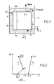
- Figures 1 and 2 represent on the one hand an example of diagram functional of a bath exchanger and on the other hand an example of heat exchange diagram between the primary fluid and the fluid secondary.
- the tank is shown in a simplified manner external 10 of the heat exchanger inside which is contained a set of passages 12 for the second "hot” fluid F2 which enters the upper part of these passages at 14 and comes out at the part lower in 16.
- the first “cold” fluid F1 to vaporize it is contained in the external enclosure 10 and circulates by thermosyphon of the lower end 12a of the passages for the second fluid F2 up to its upper end 12b, the height of this heat exchange zone being equal to h.
- the first fluid F1 at the entrance to the exchange zone is at a temperature T 1.1 and at a pressure P 1.1 .
- This temperature T 1.1 and this pressure P 1.1 correspond to a sub-cooling state, that is to say to a temperature below the bubble temperature T b1 of the fluid F1 at the pressure P 1.1 due to hydrostatic pressure due to the height of liquid F1 fluid.
- T b the temperature (bubble) at which the first gas bubble appears in the fluid F1 during the heat exchange (at intermediate pressure between P 1.1 and P 1.2 ). It is understood that the energy used to bring the primary fluid to the bubble temperature T b is "lost" energy to obtain the vaporization of the first liquid.
- the second fluid F2 has also been shown with its inlet temperature in the exchange zone 12 which is equal to T 2.1 and its outlet temperature equal to T 2.2 .
- T 2.1 the inlet temperature in the exchange zone 12
- T 2.2 the outlet temperature
- thermosyphon effect which allows the circulation of first fluid F1 is made possible by the formation of bubbles of the first fluid. If the height in the exchanger corresponding to the phase too much "subcooling", the thermosyphon effect will be insufficient.
- the outlet pressure of the first fluid P 1.2 is of the order of 4 bars absolute or greater.
- the height of the heat exchange passages between the two fluids is at least equal at 3 m.
- the heat exchange passages between the two fluids are limited by parallel plates, which can be of the type with brazed fins.
- the passages can be made up of tubes.
- the means forming enclosure include a single enclosure containing said passages heat exchange and in which the first fluid circulates by thermosyphon.
- the means forming enclosure include a first enclosure defining a lower volume of entry of the first fluid and a higher volume of first fluid outlet and a second enclosure connected respectively to the upper and lower volumes, this second enclosure that can be reduced to piping.
- the fluid to be vaporized F1 circulates by thermosyphon in the vertical heat exchange passages.
- the fluid F1 has at its inlet, that is to say at the lower end 24a of the exchange module, a temperature T 1.1 and a pressure P 1.1 , and a temperature T 1.2 and a pressure P 1.2 at the upper end 24b of the exchange module.
- the total height of the exchange module is called h, that is to say the length of circulation of the first fluid between the inlet end 24a and the outlet end 24b.
- the second fluid which is nitrogen gas in the example under consideration, enters at temperature T 2.1 through line 30 and leaves the exchange module in liquid form at temperature T 2.2 .
- FIG 4 there is shown the heat exchange between the fluid F1 (pure oxygen) and fluid F2 (pure nitrogen).
- Curve A substantially vertical due to the fact that the fluid F2 is pure nitrogen, shows the evolution of this fluid between its entry and its exit from the exchange module.
- Curve B shows the evolution of the first fluid (pure oxygen). She has a first part B1 corresponding to the "sub-cooling" of oxygen and part B2 of vaporization partial oxygen from the bubble temperature Tb of oxygen.
- the pressure P 1.2 at the outlet of the first fluid depends on the pressure at the outlet of the complete installation containing the exchanger bath taking into account the pressure drop due to the switchgear between the outlet of the exchanger and the outlet of the complete installation. If the outlet of the installation is at atmospheric pressure, the pressure at the outlet of the bath exchanger is of the order of 1.3 bar absolute.
- a bath heat exchanger can be constructed, the height h of the exchange module being equal to 3 or 4 meters, while maintaining a temperature difference of the order 1.2 ° C.
- FIG. 5 shows an alternative embodiment of the bath exchanger.
- the exchanger comprises a main enclosure 40 in which is mounted the exchange module 42.
- the enclosure 40 defines also a lower inlet chamber 44 of the first fluid and a upper chamber 46 for the outlet of the first fluid with a sampling 48 of the first vaporized fluid.
- the exchanger includes also a chamber 50 for recirculating the first fluid in the state essentially liquid which is connected to the upper chambers and lower by lines 52 and 54. This enclosure could be reduced to simple piping.
Landscapes
- Engineering & Computer Science (AREA)
- Physics & Mathematics (AREA)
- Mechanical Engineering (AREA)
- Thermal Sciences (AREA)
- General Engineering & Computer Science (AREA)
- Separation By Low-Temperature Treatments (AREA)
- Heat-Exchange Devices With Radiators And Conduit Assemblies (AREA)
Abstract
Description
- on fait circuler un deuxième fluide (F2) dans des passages verticaux d'échange, ledit deuxième fluide ayant une température de sortie T2,2 ;
- on fait circuler de bas en haut sur une hauteur h par thermosiphon ledit premier fluide entre lesdits passages d'échange thermique, ledit premier fluide ayant une température d'entrée T1,1 (T, < T2,2), la fraction vaporisée dudit premier fluide ayant une pression de sortie P1,2 ;
- on donne à ladite pression P1,2 une valeur supérieure à la pression minimale de sortie de la fraction vaporisée du premier fluide nécessaire pour permettre le fonctionnement de l'installation dans laquelle est monté ledit échangeur ; et
- on choisit la hauteur h des passages d'échange thermique et
la température T2,2 dudit deuxième fluide de telle manière qu'au moins une
des deux conditions suivantes soit remplie :
- la hauteur h desdits passages d'échange thermique est au moins égale à 2,5 m ; et
- la température T2,2 dudit deuxième fluide est inférieure à T1,1 + 1,2°C.
Claims (12)
- Echangeur vaporiseur-condenseur du type à bain entre un premier fluide (F1) à vaporiser et un deuxième fluide (F2) à condenser, ledit échangeur présentant une pression minimale de sortie PmS dudit premier fluide pour permettre le fonctionnement de l'installation dans laquelle ledit échangeur est monté, ledit échangeur comprenant :des moyens (24) pour définir une pluralité de passages (26) d'échange thermique entre les deux fluides pour faire circuler ledit deuxième fluide, ledit deuxième fluide ayant une température T2,2 à la sortie desdits passages ;des moyens formant enceinte (20) contenant les moyens formant passage (24) pour faire circuler par thermosiphon ledit premier fluide entre lesdits passages du bas vers le haut sur une hauteur h, ledit premier fluide ayant une température d'entrée T1,1 avec T1,1 < T2,2, ledit premier fluide vaporisé ayant une pression de sortie P1,2 ;des moyens pour donner à la pression d'entrée P1,1 dudit premier fluide une valeur telle que la pression P1,2 soit supérieure à ladite pression minimale PmS et des moyens pour qu'au moins une des deux conditions suivantes soit remplie :la hauteur h des passages d'échange thermique est au moins égale à 2,5 m ; etla température T2,2 dudit deuxième fluide est inférieure à T1,1 + 1,2°C.
- Echangeur vaporiseur-condenseur selon la revendication 1, caractérisé en ce que ladite pression minimale PmS étant de l'ordre de 1,3 bars absolus, la pression de sortie P1,2 dudit premier fluide à vaporiser est de l'ordre de 4 bars absolus ou supérieure.
- Echangeur vaporiseur-condenseur selon les revendications 1 et 2, caractérisé en ce que la hauteur desdits passages, d'échange (26) est au moins égale à 3 mètres.
- Echangeur selon l'une quelconque des revendications 1 à 3, caractérisé en ce que ladite température T2,2 du second fluide est comprise entre T1,1 + 1,2°C et T1,1 + 0,4°C.
- Echangeur selon l'une quelconque des revendications 1 à 4, caractérisé en ce que lesdits passages d'échange thermique (26) sont limités par des plaques parallèles.
- Echangeur selon la revendication 5, caractérisé en ce que lesdites plaques parallèles sont du type à ailettes brasées.
- Echangeur selon l'une quelconque des revendications 1 à 4, caractérisé en ce que lesdits passages d'échange thermique (26) sont des tubes.
- Echangeur selon l'une quelconque des revendications 1 à 7, caractérisé en ce que lesdits moyens formant enceinte comprennent une unique enceinte (20) contenant lesdits passages d'échange thermique (26) et dans laquelle ledit premier fluide circule par thermosiphon.
- Echangeur selon l'une quelconque des revendications 1 à 7, caractérisé en ce que lesdits moyens formant enceinte comprennent une première enceinte (40) définissant un volume inférieur d'entrée (44) du premier fluide et un volume supérieur de sortie (46) du premier fluide et une deuxième enceinte (50) raccordée respectivement auxdits volumes supérieur et inférieur.
- Procédé de vaporisation d'un premier fluide (F1) à l'aide d'un échangeur vaporiseur-condenseur à bain comprenant les étapes suivantes :on fait circuler un deuxième fluide (F2) dans des passages verticaux d'échange, ledit deuxième fluide ayant une température de sortie T2,2 ;on fait circuler de bas en haut sur une hauteur h par thermosiphon ledit premier fluide entre lesdits passages d'échange thermique, ledit premier fluide ayant une température d'entrée T1,1 (T1,1 < T2,2), la fraction vaporisée dudit premier fluide ayant une pression de sortie P1,2 ;on donne à ladite pression P1,2 une valeur supérieure à la pression minimale de sortie de la fraction vaporisée du premier fluide nécessaire pour permettre le fonctionnement de l'installation dans laquelle est monté ledit échangeur ; eton choisit la hauteur h des passages d'échange thermique et la température T2,2 dudit deuxième fluide de telle manière qu'au moins une des deux conditions suivantes soit remplie :la hauteur h desdits passages d'échange thermique est au moins égale à 2,5 m ; etla température T2,2 dudit deuxième fluide est inférieure à T1,1 + 1,2°C.
- Application de l'échangeur selon l'une quelconque des revendications 1 à 9 à la séparation cryogénique des gaz de l'air.
- Application de l'échangeur selon l'une quelconque des revendications 1 à 9 à la séparation cryogénique de gaz de synthèse.
Applications Claiming Priority (2)
| Application Number | Priority Date | Filing Date | Title |
|---|---|---|---|
| FR0004765 | 2000-04-13 | ||
| FR0004765A FR2807826B1 (fr) | 2000-04-13 | 2000-04-13 | Echangeur vaporisateur-condenseur du type a bain |
Publications (2)
| Publication Number | Publication Date |
|---|---|
| EP1146300A1 true EP1146300A1 (fr) | 2001-10-17 |
| EP1146300B1 EP1146300B1 (fr) | 2005-01-19 |
Family
ID=8849225
Family Applications (1)
| Application Number | Title | Priority Date | Filing Date |
|---|---|---|---|
| EP01400898A Revoked EP1146300B1 (fr) | 2000-04-13 | 2001-04-06 | Echangeur vaporiseur-condenseur du type à bain |
Country Status (6)
| Country | Link |
|---|---|
| US (2) | US6622784B2 (fr) |
| EP (1) | EP1146300B1 (fr) |
| JP (1) | JP2001355976A (fr) |
| CN (1) | CN1144012C (fr) |
| DE (1) | DE60108438T2 (fr) |
| FR (1) | FR2807826B1 (fr) |
Families Citing this family (10)
| Publication number | Priority date | Publication date | Assignee | Title |
|---|---|---|---|---|
| US7266976B2 (en) * | 2004-10-25 | 2007-09-11 | Conocophillips Company | Vertical heat exchanger configuration for LNG facility |
| FR2891901B1 (fr) * | 2005-10-06 | 2014-03-14 | Air Liquide | Procede de vaporisation et/ou de condensation dans un echangeur de chaleur |
| FR2935472A1 (fr) * | 2008-08-28 | 2010-03-05 | Air Liquide | Procede et appareil de separation d'un melange gazeux par distillation cryogenique |
| FR2956900B1 (fr) * | 2010-03-01 | 2012-06-01 | Air Liquide | Appareil et procede de separation d'un melange contenant du dioxyde de carbone par distillation |
| AU2012355362B2 (en) * | 2011-12-20 | 2017-02-02 | Conocophillips Company | Method and apparatus for reducing the impact of motion in a core-in-shell heat exchanger |
| CN102865759A (zh) * | 2012-09-29 | 2013-01-09 | 河南开元空分集团有限公司 | 整体式主冷热虹吸蒸发器 |
| JP6509223B2 (ja) * | 2013-12-05 | 2019-05-08 | リンデ アクチエンゲゼルシャフトLinde Aktiengesellschaft | 液相を排出するための集合通路を備えた熱交換器 |
| EP2944909A1 (fr) * | 2014-05-13 | 2015-11-18 | Linde Aktiengesellschaft | Dispositif de transmission de la chaleur doté de canaux destinés à l'amortissement de mouvements de fluides |
| US11740033B2 (en) * | 2020-12-22 | 2023-08-29 | Lane Lawless | Heat exchanger, exchanger plate, and method of construction |
| US12460873B2 (en) | 2023-10-05 | 2025-11-04 | Rygan Corp. | Heat exchanger, plate element therefor, and method of construction |
Citations (5)
| Publication number | Priority date | Publication date | Assignee | Title |
|---|---|---|---|---|
| DE1551583A1 (de) * | 1966-09-19 | 1970-06-18 | Hitachi Ltd | Rektifizierkolonne einer Lufttrennanlage |
| FR2364423A1 (fr) * | 1976-09-09 | 1978-04-07 | Union Carbide Corp | Procede et dispositif d'echange de chaleur |
| US4617036A (en) * | 1985-10-29 | 1986-10-14 | Air Products And Chemicals, Inc. | Tonnage nitrogen air separation with side reboiler condenser |
| US5071458A (en) * | 1989-07-28 | 1991-12-10 | L'air Liquide, Societe Anonyme Pour L'etude Et L'exploitation Des Procedes Georges Claude | Vaporization-condensation apparatus for air distillation double column, and air distillation equipment including such apparatus |
| US5901574A (en) * | 1996-02-14 | 1999-05-11 | Linde Aktiengesellschaft | Device and process for evaporating a liquid |
Family Cites Families (13)
| Publication number | Priority date | Publication date | Assignee | Title |
|---|---|---|---|---|
| US3835920A (en) * | 1972-02-22 | 1974-09-17 | Gen Motors Corp | Compact fluid heat exchanger |
| US4113435A (en) * | 1973-07-16 | 1978-09-12 | Massachusetts Institute Of Technology | Cryogenically controlled direct fluorination apparatus |
| US4582121A (en) * | 1977-06-09 | 1986-04-15 | Casey Charles B | Apparatus for and method of heat transfer |
| EP0063195B1 (fr) * | 1981-04-09 | 1990-03-14 | Heat Exchanger Industries, Inc. | Procédé et dispositif pour le traitement des gaz d'échappement |
| FR2547898B1 (fr) | 1983-06-24 | 1985-11-29 | Air Liquide | Procede et dispositif pour vaporiser un liquide par echange de chaleur avec un deuxieme fluide, et leur application a une installation de distillation d'air |
| US4715433A (en) * | 1986-06-09 | 1987-12-29 | Air Products And Chemicals, Inc. | Reboiler-condenser with doubly-enhanced plates |
| US5167274A (en) * | 1988-08-26 | 1992-12-01 | Cominco Ltd. | Method and apparatus for cooling particulate solids |
| US5031693A (en) | 1990-10-31 | 1991-07-16 | Sundstrand Corporation | Jet impingement plate fin heat exchanger |
| US5122174A (en) * | 1991-03-01 | 1992-06-16 | Air Products And Chemicals, Inc. | Boiling process and a heat exchanger for use in the process |
| FR2703762B1 (fr) | 1993-04-09 | 1995-05-24 | Maurice Grenier | Procédé et installation de refroidissement d'un fluide, notamment pour la liquéfaction de gaz naturel. |
| US5362454A (en) * | 1993-06-28 | 1994-11-08 | The M. W. Kellogg Company | High temperature heat exchanger |
| JP3681187B2 (ja) * | 1994-03-31 | 2005-08-10 | 大陽日酸株式会社 | 空気液化分離方法及び装置 |
| US5775412A (en) * | 1996-01-11 | 1998-07-07 | Gidding Engineering, Inc. | High pressure dense heat transfer area heat exchanger |
-
2000
- 2000-04-13 FR FR0004765A patent/FR2807826B1/fr not_active Expired - Fee Related
-
2001
- 2001-04-06 DE DE60108438T patent/DE60108438T2/de not_active Expired - Lifetime
- 2001-04-06 EP EP01400898A patent/EP1146300B1/fr not_active Revoked
- 2001-04-10 US US09/829,050 patent/US6622784B2/en not_active Expired - Lifetime
- 2001-04-10 JP JP2001110707A patent/JP2001355976A/ja active Pending
- 2001-04-13 CN CNB011163933A patent/CN1144012C/zh not_active Expired - Fee Related
-
2003
- 2003-02-20 US US10/368,458 patent/US6761213B2/en not_active Expired - Lifetime
Patent Citations (5)
| Publication number | Priority date | Publication date | Assignee | Title |
|---|---|---|---|---|
| DE1551583A1 (de) * | 1966-09-19 | 1970-06-18 | Hitachi Ltd | Rektifizierkolonne einer Lufttrennanlage |
| FR2364423A1 (fr) * | 1976-09-09 | 1978-04-07 | Union Carbide Corp | Procede et dispositif d'echange de chaleur |
| US4617036A (en) * | 1985-10-29 | 1986-10-14 | Air Products And Chemicals, Inc. | Tonnage nitrogen air separation with side reboiler condenser |
| US5071458A (en) * | 1989-07-28 | 1991-12-10 | L'air Liquide, Societe Anonyme Pour L'etude Et L'exploitation Des Procedes Georges Claude | Vaporization-condensation apparatus for air distillation double column, and air distillation equipment including such apparatus |
| US5901574A (en) * | 1996-02-14 | 1999-05-11 | Linde Aktiengesellschaft | Device and process for evaporating a liquid |
Also Published As
| Publication number | Publication date |
|---|---|
| DE60108438T2 (de) | 2006-01-12 |
| US6622784B2 (en) | 2003-09-23 |
| EP1146300B1 (fr) | 2005-01-19 |
| CN1144012C (zh) | 2004-03-31 |
| US20030150602A1 (en) | 2003-08-14 |
| US6761213B2 (en) | 2004-07-13 |
| DE60108438D1 (de) | 2005-02-24 |
| CN1317677A (zh) | 2001-10-17 |
| US20010030042A1 (en) | 2001-10-18 |
| FR2807826A1 (fr) | 2001-10-19 |
| FR2807826B1 (fr) | 2002-06-14 |
| JP2001355976A (ja) | 2001-12-26 |
Similar Documents
| Publication | Publication Date | Title |
|---|---|---|
| EP1146300B1 (fr) | Echangeur vaporiseur-condenseur du type à bain | |
| CA2876619C (fr) | Procede et appareil de purification d'un melange riche en dioxyde de carbone a basse temperature | |
| WO2020025873A1 (fr) | Echangeur de chaleur a configuration de passages amelioree, procedes d'echange de chaleur associes | |
| EP2265855B1 (fr) | Procédé de vaporisation d'un liquide cryogénique par échange de chaleur avec un fluide calorigène | |
| FR2710370A1 (fr) | Procédé et ensemble de compression d'un gaz. | |
| FR2573185A1 (fr) | Echangeur de chaleur a chauffage direct | |
| EP2149021A2 (fr) | Capacite de stockage, appareil et procede de production de monoxyde de carbone et/ou d'hydrogene par separation cryogenique integrant une telle capacite | |
| FR3010509A1 (fr) | Procede et appareil de separation a temperature subambiante | |
| EP1966554B1 (fr) | Appareil de séparation d'air par distillation cryogénique | |
| FR3110917A3 (fr) | Intégration d’une unité de reformage/oxydation partielle avec un électrolyseur fonctionnant de manière discontinue. | |
| BE1009886A5 (fr) | Procede et dispositif pour la production d'eau par condensation de l'humidite presente dans l'air atmospherique. | |
| EP4092356B1 (fr) | Machine à absorption comprenant des échangeurs à plaque en spirale | |
| EP3812675B1 (fr) | Procédé et appareil de séparation d'air par distillation cryogénique | |
| WO2014049259A1 (fr) | Procédé et appareil de séparation d'un mélange contenant du dioxyde de carbone par distillation cryogénique | |
| FR2707375A1 (fr) | Procédé d'obtention de très basses températures. | |
| WO2005047790A2 (fr) | Procede et installation d'enrichissement d'un flux gazeux en l'un de ses constituants | |
| WO2021019160A1 (fr) | Échangeur de chaleur avec configuration de passages et structures d'échange thermique ameliorées et procédé de refroidissement en utilisant au moins un tel échangeur | |
| WO2009136076A2 (fr) | Procede et appareil de separation d'air par distillation cryogenique | |
| FR3033397A1 (fr) | Procede de compression et de refroidissement d’un melange gazeux | |
| WO2023174601A1 (fr) | Procédé et appareil de refroidissement d'hydrogène | |
| WO2016132086A1 (fr) | Procede et appareil de separation a temperature subambiante | |
| FR2811712A1 (fr) | Installation de distillation d'air et de production d'electricite et procede correspondant | |
| FR2756621A1 (fr) | Thermo-frigopompe | |
| FR2679632A1 (fr) | Installation pour produire du froid par reaction solide/gaz, le reacteur comportant des moyens de chauffage. | |
| FR2930326A1 (fr) | Procede et appareil de separation d'air par distillation cryogenique |
Legal Events
| Date | Code | Title | Description |
|---|---|---|---|
| PUAI | Public reference made under article 153(3) epc to a published international application that has entered the european phase |
Free format text: ORIGINAL CODE: 0009012 |
|
| AK | Designated contracting states |
Kind code of ref document: A1 Designated state(s): AT BE CH CY DE DK ES FI FR GB GR IE IT LI LU MC NL PT SE TR Kind code of ref document: A1 Designated state(s): DE FR GB |
|
| AX | Request for extension of the european patent |
Free format text: AL;LT;LV;MK;RO;SI |
|
| RAP1 | Party data changed (applicant data changed or rights of an application transferred) |
Owner name: L'AIR LIQUIDE, SOCIETE ANONYME POUR L'ETUDE ET L'E |
|
| RAP1 | Party data changed (applicant data changed or rights of an application transferred) |
Owner name: L'AIR LIQUIDE, S.A. A DIRECTOIRE ET CONSEIL DE SUR |
|
| 17P | Request for examination filed |
Effective date: 20020225 |
|
| AKX | Designation fees paid |
Free format text: DE FR GB |
|
| 17Q | First examination report despatched |
Effective date: 20030723 |
|
| GRAP | Despatch of communication of intention to grant a patent |
Free format text: ORIGINAL CODE: EPIDOSNIGR1 |
|
| GRAS | Grant fee paid |
Free format text: ORIGINAL CODE: EPIDOSNIGR3 |
|
| GRAA | (expected) grant |
Free format text: ORIGINAL CODE: 0009210 |
|
| AK | Designated contracting states |
Kind code of ref document: B1 Designated state(s): DE FR GB |
|
| REG | Reference to a national code |
Ref country code: GB Ref legal event code: FG4D Free format text: NOT ENGLISH |
|
| REF | Corresponds to: |
Ref document number: 60108438 Country of ref document: DE Date of ref document: 20050224 Kind code of ref document: P |
|
| GBT | Gb: translation of ep patent filed (gb section 77(6)(a)/1977) |
Effective date: 20050414 |
|
| PLBI | Opposition filed |
Free format text: ORIGINAL CODE: 0009260 |
|
| PLAX | Notice of opposition and request to file observation + time limit sent |
Free format text: ORIGINAL CODE: EPIDOSNOBS2 |
|
| 26 | Opposition filed |
Opponent name: LINDE AKTIENGESELLSCHAFT Effective date: 20051019 |
|
| PLAF | Information modified related to communication of a notice of opposition and request to file observations + time limit |
Free format text: ORIGINAL CODE: EPIDOSCOBS2 |
|
| PLBB | Reply of patent proprietor to notice(s) of opposition received |
Free format text: ORIGINAL CODE: EPIDOSNOBS3 |
|
| RAP2 | Party data changed (patent owner data changed or rights of a patent transferred) |
Owner name: L'AIR LIQUIDE, SOCIETE ANONYME POUR L'ETUDE ET L'E |
|
| RAP2 | Party data changed (patent owner data changed or rights of a patent transferred) |
Owner name: L'AIR LIQUIDE, SOCIETE ANONYME POUR L'ETUDE ET L'E |
|
| PLCK | Communication despatched that opposition was rejected |
Free format text: ORIGINAL CODE: EPIDOSNREJ1 |
|
| APBM | Appeal reference recorded |
Free format text: ORIGINAL CODE: EPIDOSNREFNO |
|
| APBP | Date of receipt of notice of appeal recorded |
Free format text: ORIGINAL CODE: EPIDOSNNOA2O |
|
| APAH | Appeal reference modified |
Free format text: ORIGINAL CODE: EPIDOSCREFNO |
|
| APAW | Appeal reference deleted |
Free format text: ORIGINAL CODE: EPIDOSDREFNO |
|
| APAY | Date of receipt of notice of appeal deleted |
Free format text: ORIGINAL CODE: EPIDOSDNOA2O |
|
| APBM | Appeal reference recorded |
Free format text: ORIGINAL CODE: EPIDOSNREFNO |
|
| APBP | Date of receipt of notice of appeal recorded |
Free format text: ORIGINAL CODE: EPIDOSNNOA2O |
|
| APAH | Appeal reference modified |
Free format text: ORIGINAL CODE: EPIDOSCREFNO |
|
| APBQ | Date of receipt of statement of grounds of appeal recorded |
Free format text: ORIGINAL CODE: EPIDOSNNOA3O |
|
| PGFP | Annual fee paid to national office [announced via postgrant information from national office to epo] |
Ref country code: FR Payment date: 20110510 Year of fee payment: 11 Ref country code: DE Payment date: 20110421 Year of fee payment: 11 |
|
| PGFP | Annual fee paid to national office [announced via postgrant information from national office to epo] |
Ref country code: GB Payment date: 20110421 Year of fee payment: 11 |
|
| APBU | Appeal procedure closed |
Free format text: ORIGINAL CODE: EPIDOSNNOA9O |
|
| REG | Reference to a national code |
Ref country code: DE Ref legal event code: R064 Ref document number: 60108438 Country of ref document: DE Ref country code: DE Ref legal event code: R103 Ref document number: 60108438 Country of ref document: DE |
|
| RDAF | Communication despatched that patent is revoked |
Free format text: ORIGINAL CODE: EPIDOSNREV1 |
|
| RDAG | Patent revoked |
Free format text: ORIGINAL CODE: 0009271 |
|
| STAA | Information on the status of an ep patent application or granted ep patent |
Free format text: STATUS: PATENT REVOKED |
|
| 27W | Patent revoked |
Effective date: 20111008 |
|
| GBPR | Gb: patent revoked under art. 102 of the ep convention designating the uk as contracting state |
Effective date: 20111008 |
|
| REG | Reference to a national code |
Ref country code: DE Ref legal event code: R107 Ref document number: 60108438 Country of ref document: DE Effective date: 20120405 |