EP1146207B1 - Process for checking the functioning of a nitrogen oxide storage catalyst - Google Patents
Process for checking the functioning of a nitrogen oxide storage catalyst Download PDFInfo
- Publication number
- EP1146207B1 EP1146207B1 EP01108460A EP01108460A EP1146207B1 EP 1146207 B1 EP1146207 B1 EP 1146207B1 EP 01108460 A EP01108460 A EP 01108460A EP 01108460 A EP01108460 A EP 01108460A EP 1146207 B1 EP1146207 B1 EP 1146207B1
- Authority
- EP
- European Patent Office
- Prior art keywords
- nitrogen oxide
- exhaust gas
- oxide storage
- nitrogen
- catalyst
- Prior art date
- Legal status (The legal status is an assumption and is not a legal conclusion. Google has not performed a legal analysis and makes no representation as to the accuracy of the status listed.)
- Expired - Lifetime
Links
Images

Classifications
-
- F—MECHANICAL ENGINEERING; LIGHTING; HEATING; WEAPONS; BLASTING
- F01—MACHINES OR ENGINES IN GENERAL; ENGINE PLANTS IN GENERAL; STEAM ENGINES
- F01N—GAS-FLOW SILENCERS OR EXHAUST APPARATUS FOR MACHINES OR ENGINES IN GENERAL; GAS-FLOW SILENCERS OR EXHAUST APPARATUS FOR INTERNAL COMBUSTION ENGINES
- F01N3/00—Exhaust or silencing apparatus having means for purifying, rendering innocuous, or otherwise treating exhaust
- F01N3/08—Exhaust or silencing apparatus having means for purifying, rendering innocuous, or otherwise treating exhaust for rendering innocuous
- F01N3/0807—Exhaust or silencing apparatus having means for purifying, rendering innocuous, or otherwise treating exhaust for rendering innocuous by using absorbents or adsorbents
- F01N3/0828—Exhaust or silencing apparatus having means for purifying, rendering innocuous, or otherwise treating exhaust for rendering innocuous by using absorbents or adsorbents characterised by the absorbed or adsorbed substances
- F01N3/0864—Oxygen
-
- F—MECHANICAL ENGINEERING; LIGHTING; HEATING; WEAPONS; BLASTING
- F01—MACHINES OR ENGINES IN GENERAL; ENGINE PLANTS IN GENERAL; STEAM ENGINES
- F01N—GAS-FLOW SILENCERS OR EXHAUST APPARATUS FOR MACHINES OR ENGINES IN GENERAL; GAS-FLOW SILENCERS OR EXHAUST APPARATUS FOR INTERNAL COMBUSTION ENGINES
- F01N11/00—Monitoring or diagnostic devices for exhaust-gas treatment apparatus, e.g. for catalytic activity
-
- F—MECHANICAL ENGINEERING; LIGHTING; HEATING; WEAPONS; BLASTING
- F01—MACHINES OR ENGINES IN GENERAL; ENGINE PLANTS IN GENERAL; STEAM ENGINES
- F01N—GAS-FLOW SILENCERS OR EXHAUST APPARATUS FOR MACHINES OR ENGINES IN GENERAL; GAS-FLOW SILENCERS OR EXHAUST APPARATUS FOR INTERNAL COMBUSTION ENGINES
- F01N3/00—Exhaust or silencing apparatus having means for purifying, rendering innocuous, or otherwise treating exhaust
- F01N3/08—Exhaust or silencing apparatus having means for purifying, rendering innocuous, or otherwise treating exhaust for rendering innocuous
- F01N3/0807—Exhaust or silencing apparatus having means for purifying, rendering innocuous, or otherwise treating exhaust for rendering innocuous by using absorbents or adsorbents
- F01N3/0828—Exhaust or silencing apparatus having means for purifying, rendering innocuous, or otherwise treating exhaust for rendering innocuous by using absorbents or adsorbents characterised by the absorbed or adsorbed substances
- F01N3/0842—Nitrogen oxides
-
- F—MECHANICAL ENGINEERING; LIGHTING; HEATING; WEAPONS; BLASTING
- F01—MACHINES OR ENGINES IN GENERAL; ENGINE PLANTS IN GENERAL; STEAM ENGINES
- F01N—GAS-FLOW SILENCERS OR EXHAUST APPARATUS FOR MACHINES OR ENGINES IN GENERAL; GAS-FLOW SILENCERS OR EXHAUST APPARATUS FOR INTERNAL COMBUSTION ENGINES
- F01N2550/00—Monitoring or diagnosing the deterioration of exhaust systems
- F01N2550/03—Monitoring or diagnosing the deterioration of exhaust systems of sorbing activity of adsorbents or absorbents
-
- F—MECHANICAL ENGINEERING; LIGHTING; HEATING; WEAPONS; BLASTING
- F02—COMBUSTION ENGINES; HOT-GAS OR COMBUSTION-PRODUCT ENGINE PLANTS
- F02D—CONTROLLING COMBUSTION ENGINES
- F02D41/00—Electrical control of supply of combustible mixture or its constituents
- F02D41/02—Circuit arrangements for generating control signals
- F02D41/14—Introducing closed-loop corrections
- F02D41/1438—Introducing closed-loop corrections using means for determining characteristics of the combustion gases; Sensors therefor
- F02D41/1444—Introducing closed-loop corrections using means for determining characteristics of the combustion gases; Sensors therefor characterised by the characteristics of the combustion gases
- F02D2041/147—Introducing closed-loop corrections using means for determining characteristics of the combustion gases; Sensors therefor characterised by the characteristics of the combustion gases the characteristics being a hydrogen content or concentration of the exhaust gases
-
- Y—GENERAL TAGGING OF NEW TECHNOLOGICAL DEVELOPMENTS; GENERAL TAGGING OF CROSS-SECTIONAL TECHNOLOGIES SPANNING OVER SEVERAL SECTIONS OF THE IPC; TECHNICAL SUBJECTS COVERED BY FORMER USPC CROSS-REFERENCE ART COLLECTIONS [XRACs] AND DIGESTS
- Y02—TECHNOLOGIES OR APPLICATIONS FOR MITIGATION OR ADAPTATION AGAINST CLIMATE CHANGE
- Y02T—CLIMATE CHANGE MITIGATION TECHNOLOGIES RELATED TO TRANSPORTATION
- Y02T10/00—Road transport of goods or passengers
- Y02T10/10—Internal combustion engine [ICE] based vehicles
- Y02T10/40—Engine management systems
Definitions
- the present invention relates to a method for checking the functionality a nitrogen oxide storage catalytic converter, which is used for the removal of the in the exhaust gas stream of a lean-burn nitrogen oxide is used and at least one Nitric oxide storage material, a catalytically active component and optionally one Contains oxygen storage material, the lean engine with cyclical change of the air / fuel mixture is operated from lean to rich and in the exhaust gas nitrogen oxides contained in the lean exhaust gas stored by the nitrogen oxide storage material (Storage phase) and desorbed and converted in the case of rich exhaust gas (regeneration phase).
- Nitrogen oxide storage catalytic converters were specially developed for lean exhaust gas cleaning operated internal combustion engines developed.
- lean-burn internal combustion engines include diesel engines and lean gasoline engines. Both Engine types are referred to below as lean engines.
- Lean engines, in particular Gasoline engines with direct injection are increasingly used in motor vehicle construction used, as compared to a theoretical fuel saving of up to 25% enable stoichiometrically operated internal combustion engines.
- Nitrogen oxide storage catalysts have the ability to operate in a wide temperature range Nitrogen oxides under oxidizing exhaust gas conditions, i.e. in lean operation to save. This operating phase is therefore also referred to below as the storage phase.
- the storage capacity of a storage catalytic converter Since the storage capacity of a storage catalytic converter is limited, it has to be used from time to time Time to be regenerated.
- the air ratio of the engine is fed Air / fuel mixture and thus also the air ratio of the person leaving the engine Exhaust gas reduced to values below 1 for a short time. This is also called the enrichment of the Air / fuel mixture or the exhaust gas. During this short phase of operation are therefore reducing in the exhaust gas before entering the storage catalytic converter Conditions.
- the saved ones Nitrogen oxides released and on the storage catalytic converter with simultaneous oxidation of carbon monoxide, hydrocarbons and hydrogen as with conventional ones Three-way catalysts reduced to nitrogen.
- This operating phase of the storage catalytic converter is also referred to below as the regeneration phase. If correct Function of the overall system consisting of storage catalytic converter, oxygen sensors and Engine electronics are behind the storage catalytic converter during the regeneration phase roughly stoichiometric conditions, that is, before the storage catalytic converter hydrocarbons present in excess during the regeneration phase and Carbon monoxide is oxidized on the storage catalytic converter by the released nitrogen oxides. Only after the regeneration is completed there is a sudden increase in reductive components behind the catalyst. This is called the breakthrough of reductive Components designated by the storage catalytic converter.
- the duration of the storage phase is typically about 30 to 100 seconds.
- the duration of the regeneration phase is much shorter and is only in the range of a few Seconds (1 to 20 seconds).
- Nitrogen oxide storage catalysts are for Example known from EP 0 560 991 B1. These contain catalysts as storage material at least one component from the group of alkali metals (e.g. potassium, Sodium, lithium, cesium), the alkaline earth metals (e.g. barium, calcium) or the rare earth metals (e.g. lanthanum, yttrium).
- the storage catalytic converter contains the catalytically active element Platinum. Under oxidizing exhaust gas conditions, i.e. in lean operation, can the storage materials in the form of nitrogen oxides contained in the exhaust gas Save nitrates. However, this requires that the nitrogen oxides, which depending on Design of the engine and its mode of operation to about 60 to 95% from nitrogen monoxide exist, are first oxidized to nitrogen dioxide. This happens on the platinum component of the storage catalytic converter.
- the nitrogen oxide storage catalytic converter can also contain oxygen storing components included. In this case, he can next to the Nitrogen oxide storage also functions as a conventional three-way catalytic converter take. For the most part, cerium oxide is used as the oxygen-storing component used. The nitrogen oxide storage catalytic converter then has, in addition to its nitrogen oxide storage function also an oxygen storage function, it is therefore bifunctional.
- Nitric oxide storage catalysts in which various aging mechanisms are observed become. On the one hand, they can be caused by the sulfur present in the fuel and secondly due to thermal overload in their nitrogen oxide storage capacity be harmed. During sulfur poisoning usually through regeneration can be reversed at elevated temperatures the thermal damage is an irreversible process.
- both storage functions can in principle (Nitrogen oxide and oxygen) can be damaged by poisoning and thermal influences.
- the damage to one function does not necessarily result in the Damage to the other function.
- nitrogen oxides and oxygen are both oxidizing Components, their effects cannot be clearly separated, so that misdiagnosis can occur when testing the catalytic converter.
- a method for checking the functionality of a nitrogen oxide storage catalytic converter which allows the oxygen storage function and the nitrogen oxide storage function of the catalytic converter to be assessed separately.
- the air ratio of the exhaust gas is switched from lean to rich and the time offset ⁇ t 1 that results between the first changeover to the breakthrough of the rich exhaust gas by the catalytic converter and that after renewed switching of the exhaust gas from rich to lean resulting time offset .DELTA.t 2 measured between the second switching and the breakthrough of oxygen through the catalyst.
- the time differences ⁇ t 1 and ⁇ t 2 allow the oxygen storage function and the nitrogen oxide storage function of the catalytic converter to be assessed separately.
- the nitrogen oxide storage function of the catalyst depends on the nitrogen oxide storage material and on the catalytically active component, usually platinum. Both that Nitric oxide storage material as well as the catalytically active component can be damaged become.
- the nitrogen oxide storage material stores the sulfur dioxide contained in the exhaust gas Form of sulfates. This affects the nitrogen oxide storage capacity.
- the sulfates of the storage material are much more stable than the nitrates. However, you can at Exhaust gas temperatures above 600 ° C and under reducing conditions again be decomposed. This desulphation preserves the nitrogen oxide storage material largely returned to its original nitrogen oxide storage capacity.
- the nitrogen oxide storage capacity of the storage material depends crucially on its specific surface with which it can interact with the exhaust gas. If the storage material is exposed to exhaust gas temperatures above approximately 800 ° C, then its specific surface area decreases irreversibly and its nitrogen oxide storage capacity decreases.
- the catalytically active component For optimal use of the catalytically active component, it is on the oxidic Storage catalyst materials in highly disperse form with medium particle sizes applied between about 2 and 15 nm. Own because of the fine distribution the platinum particles have a high surface area for interaction with the components of the exhaust gas. Especially in the lean exhaust gas from lean-burn engines increases with Exhaust gas temperature observed an irreversible increase, for example of the platinum crystallites, which is accompanied by an irreversible decrease in catalytic activity.
- a nitrogen oxide storage catalytic converter which is used for the removal of the in the exhaust gas stream of a lean-burn nitrogen oxide is used and at least one Nitric oxide storage material, a catalytically active component and optionally one Contains oxygen storage material, the lean engine with cyclical change of the air / fuel mixture is operated from lean to rich and in the exhaust gas nitrogen oxides contained in the lean exhaust gas stored by the nitrogen oxide storage material (Storage phase) and desorbed and converted in the case of rich exhaust gas (regeneration phase).
- the method is characterized in that for determining a possible Damage to the catalytically active component, the nitrogen oxide storage capacity of the nitrogen oxide storage catalyst is determined at exhaust gas temperatures, which in a Range in which the oxidation of nitrogen monoxide to nitrogen dioxide is kinetic is controlled, while in the thermodynamically controlled area no change the nitrogen oxide storage capacity is to be determined, and that to determine a possible damage to the storage materials the nitrogen oxide storage capacity of the Nitrogen oxide storage catalytic converter is determined at exhaust gas temperatures in a Range in which the oxidation of nitrogen monoxide to nitrogen dioxide is thermodynamic is checked.
- the method according to the invention is based on the considerations to be set out below on the mode of action of nitrogen oxide storage catalysts.
- the Nitrogen oxides of the exhaust gas in the form of nitrates of the storage material on the catalyst bound only nitrogen dioxide reacts with the storage material corresponding nitrates. Since about 60 to 95 vol .-% of nitrogen oxides in the exhaust gas of internal combustion engines consist of nitrogen monoxide, this must first be catalytically active components of the storage catalytic converter are oxidized to nitrogen dioxide, before it can react with the storage material to form nitrates.
- the measurement is kinetically controlled Range below 300 ° C and in the thermodynamically controlled range preferably between 350 and 450 ° C.
- the nitrogen oxide storage capacity of the catalyst is in the kinetically controlled temperature range strongly depends on the available surface of the platinum particles.
- the platinum surface plays in the thermodynamically controlled area Formation of nitrogen dioxide only plays a subordinate role.
- the decisive one The factor for nitrogen oxide storage capacity in this area is rapid removal of the nitrogen dioxide formed from the equilibrium according to the reaction equation (1) by reaction with the storage material to give nitrates, resulting in one of the Equilibrium leads to the formation of new nitrogen dioxide.
- the nitrate formation depends on possible damage to the storage material by thermal Influences or by sulfur poisoning.
- Various types of sensors can be used to check the nitrogen oxide storage capacity be used. Both nitrogen oxide probes and lambda linear probes, Lambda jump probes, hydrocarbon probes, carbon monoxide probes or hydrogen probes can be used. It is also possible to use the Nitric oxide storage capacity based on changing one of the amount stored Nitrogen oxide dependent physical property of the storage catalytic converter determine.
- the complex impedance of the catalyst is particularly suitable for this. A method for determining the nitrogen oxide storage capacity of a storage catalytic converter based on its complex impedance, for example, in EP 0 936 348 A2 described.
- a nitrogen oxide probe is able to directly measure the nitrogen oxide concentration in the exhaust gas measure up.
- the available nitrogen oxide probes produce simultaneously due to their structure also a linear and a sudden signal for the oxygen content of the exhaust gas (Lambda signal).
- a lambda linear probe provides a probe signal that is linear with the oxygen content of the exhaust gas increases.
- the mode of operation of the lambda probes suitable for the method will be in the automotive engineering paperback by Bosch, VDI-Verlag, 20th edition from 1995, Pages 490 to 492.
- hydrocarbon, Carbon monoxide and hydrogen probes are used. These types of probes are located are currently in development and are not yet ready for series production. Even with these Probes can breakthrough the rich exhaust gas through the catalyst at the end of the Regeneration phase can be determined.
- the nitrogen oxide probe When using a nitrogen oxide probe, it is possible to directly determine the nitrogen oxide storage capacity of the storage catalytic converter.
- the nitrogen oxide probe is arranged behind the storage catalytic converter in the exhaust gas stream. If the nitrogen oxide concentration exceeds a predefined threshold value during the storage phase, regeneration is initiated by the engine control. From the maps stored in the engine control, it is possible to calculate the amount of nitrogen oxides emitted up to this point by integrating them through the operating states of the engine and to compare them with the storage capacity of the catalytic converter in the fresh state. If the amount of nitrogen oxides added up until the threshold value is reached is substantially below the storage capacity of the fresh catalyst, the storage capacity is damaged. The time from the beginning of a storage phase until the threshold value for regeneration is reached is referred to below as ⁇ t s .
- a catalytic damage active component is present when in the kinetically controlled range at temperatures the exhaust gas below 300 ° C a reduction in nitrogen oxide storage capacity is detected while in the thermodynamically controlled area above 300 ° C, preferably in the temperature range of 350 - 450 ° C, none Change in nitrogen oxide storage capacity is noticeable.
- the determination of possible damage to the storage materials is carried out at temperatures of the exhaust gas above 300 ° C, preferably in the temperature range of 350 - 450 ° C. If damage is found here, it can be caused by are caused by sulfurization or thermal damage to the storage material consist. In the first case, it is a reversible damage caused by Desulfurization of the storage material can be reversed in the the second case is permanent damage. To distinguish this Both damage mechanisms are therefore recognized after damage to the Storage material initiated a desulfation of the nitrogen oxide storage catalyst.
- the nitrogen oxide storage capacity can only be determined indirectly during the regeneration phase. These probes are used to measure the time offset ⁇ t 1 between the switching of the air / fuel mixture from lean to rich and the breakthrough of the rich exhaust gas through the nitrogen oxide storage catalytic converter. This time difference is caused by the action of the nitrogen oxide storage material and by the oxygen storage material of the catalyst which may be present. The smaller the storage capacity of the catalyst for nitrogen oxides and possibly oxygen, the smaller the time difference.
- the resulting time offset ⁇ t 2 between the second switching and the breakthrough of the oxygen through the catalytic converter must be carried out after the air / fuel mixture has been switched from rich to lean again be measured. This time offset is only dependent on the oxygen storage capacity of the catalytic converter.
- the nitrogen oxides are released the reductive components of the exhaust gas (hydrocarbons, carbon monoxide and Desorbed hydrogen and implemented on the storage catalyst.
- the reductive components of the exhaust gas using the stored oxygen oxidized. Nitrogen oxide storage material and oxygen storage material are thus in the rich exhaust gas emptied.
- the air ratio of the exhaust gas behind the catalytic converter follows the change in air ratio before Catalyst not spontaneously, but only with a certain delay and stays as long the storage materials are not empty, nor in the lean area, so a behind the catalyst still a lean exhaust gas composition would report. Only when nitrogen oxide storage material and oxygen storage material are emptied, hydrocarbons, carbon monoxide and hydrogen are no longer implemented. These substances then break through the catalyst and the air number of the exhaust gas behind the catalytic converter changes to the rich range. This The point in time can be determined in a simple manner using the probes mentioned.
- the stored nitrogen oxides are usually released faster than that on the Catalyst stored oxygen consumed by the hydrocarbons in the rich exhaust gas, or emptied.
- the air ratio can be used for the method according to the invention during the fat phase in an interval between 0.7 and 0.99.
- the emptying of the accumulator takes place more slowly than with a lower value of the air ratio. This enables a higher accuracy of the time measurement.
- the reductive components do not break through the catalyst until the nitrogen oxide storage material and oxygen storage material have been completely emptied, so that the time difference ⁇ t 1 to be measured reflects the sum of both storage capacities.
- the emptying of the nitrogen oxide and oxygen storage when switching the air ratio from lean to rich is countered by a corresponding filling of the oxygen storage after the end of the rich phase.
- the air ratio behind the catalytic converter does not spontaneously follow the air ratio before the catalytic converter even after switching from rich to lean.
- the air ratio initially remains in the rich range, since the excess of oxygen in the lean exhaust gas is now only used to fill up the oxygen reservoir.
- a jump lambda probe arranged behind the catalytic converter would therefore continue to display a rich exhaust gas. Only after the oxygen storage has been filled does the oxygen break through the catalyst appreciably and thus, in the case of a measurement with a step probe, the probe signal jumps.
- the measurable time difference ⁇ t 2 between the termination of the fat phase and the breakthrough of the oxygen through the catalyst is a measure of the storage capacity of the oxygen store. If the oxygen storage capacity of the catalyst drops due to sulfur poisoning or thermal damage, this is noticeable by a reduction in ⁇ t 2 and a signal for replacing the catalyst can be set if necessary.
- a and b denote proportionality constants.
- K NOx and K O2 denote the storage capacities of the catalyst for nitrogen oxides and oxygen.
- Relationship (2) reflects the finding that ⁇ t 1 is due to both storage capacities. It is clearly evident that the effect of the two storage capacities cannot be separated from one another by measuring ⁇ t 1 alone. The determination of ⁇ t 2 is therefore used as a further measurement.
- Equation (2) and (3) thus enable the separate assessment of both functions by measuring ⁇ t 1 and ⁇ t 2 even when a nitrogen oxide storage function and an oxygen storage function are present in the storage catalytic converter at the same time.
- the time differences ⁇ t 1 and ⁇ t 2 can be determined in various ways. It is thus possible to determine the time differences ⁇ t 1 and ⁇ t 2 from the difference between the respective point in time at which the air ratio is switched over by the engine control and the respective point in time at which the air ratio changes behind the catalytic converter. In the case of long exhaust gas lines between the engine and the storage catalytic converter, the time differences determined in this way may have to be corrected for the running times of the exhaust gas between the engine and the catalytic converter. Alternatively, the changes in the air ratio upstream and downstream of the catalytic converter can be determined with a probe to determine the time differences.
- Table 1 gives an overview of the method used by the invention Resulting assessment options of the nitrogen oxide storage catalyst when used different probes. Two groups can be distinguished with regard to the probes become.
- the duration of the storage phase ⁇ t s can be measured using a nitrogen oxide probe or a property probe for a physical property of the storage catalytic converter.
- the measurement can be carried out in the kinetically (kin) as well as in the thermodynamically (therm) controlled temperature range. If a reduction of ⁇ t s is found in the kinetically controlled area ( ), this may have been caused by the damage mechanisms listed in the left column of the table. The detection of irreversible damage to the oxygen storage material is not possible with this (no detectable change compared to the previous state of the catalyst, O). If a control measurement in the thermodynamically controlled area does not show any change in ⁇ t s compared to the previous measurement in this area, then there is thermal damage to the catalytically active component.
- a further distinction between the damage mechanisms is possible if the storage catalytic converter is desulfated after damage has been determined.
- the exhaust gas temperature is increased above 650 ° C for rich exhaust gas.
- the time period of the storage phase to be measured after desulfation is designated in Table 1 with ⁇ t s, DeSOx . If this time does not change compared to ⁇ t s , there is irreversible damage to the nitrogen oxide storage material and the oxygen storage material which may be present.
- ⁇ t s, DeSOx is greater than ⁇ t s , that is, the damage could be reversed by the desulfation, then there was only reversible poisoning of the nitrogen oxide storage material and possibly the oxygen storage material.
- the already defined time differences ⁇ t 1 and ⁇ t 2 can be measured with an oxygen, hydrogen, hydrocarbon or a carbon monoxide probe.
- ⁇ t 1, DeSOx , and ⁇ t 2, DeSOx the time differences ⁇ t 1 and ⁇ t 2 after desulfating are designated in Table 1. According to the above explanations for the measurements with nitrogen oxide or property probe, the differentiation options listed in Table 1 result for the various damage mechanisms of the storage catalytic converter.
- a pure platinum / alumina oxidation catalyst was made for these measurements.
- 15 g of platinum were deposited on 700 g of aluminum oxide with a BET surface in the calcined fresh state of 210 m 2 / g by impregnation with an aqueous solution of platinum tetraammine nitrate and subsequent drying and calcining at 500 ° C. in air.
- the catalyst powder prepared in this way was stirred into an aqueous dispersion and ground to a particle size of 3-5 ⁇ m (d 50 ).
- a commercial honeycomb body made of cordierite was coated with this dispersion by immersing it in the dispersion.
- the coated honeycomb body was dried at 120 ° C. in a drying cabinet. Dipping and drying steps were repeated until a load of 110 g per liter of honeycomb body volume when dry. Then followed a 4-hour calcination of the coated honeycomb body at 500 ° C.
- the finished catalyst thus contained 107.7 g / l aluminum oxide and 2.3 g / l platinum.
- 550 g of a cerium / zirconium mixed oxide (90% by weight of cerium oxide and 10% by weight of zirconium oxide) with a BET surface area in the calcined fresh state of 87 m 2 / g were obtained by impregnation with aqueous barium acetate solution, followed by drying and calcining at 500 ° C in air with 100 g of barium oxide.
- the soluble barium acetate was fixed by calcining on the carrier material in the form of barium oxide or barium carbonate. This ensured that the barium acetate does not go back into solution in the subsequent production steps.
- rhodium / aluminum oxide powder 1.5 g of rhodium were deposited on 100 g of aluminum oxide with a BET surface area in the calcined fresh state of 142 m 2 / g by impregnation with an aqueous rhodium nitrate solution and subsequent drying and calcining at 500 ° C.
- the three powders produced in this way were stirred to give an aqueous dispersion and ground to a particle size of 3-5 ⁇ m (d 50 ).
- the oxidic solids content of the dispersion was applied to commercially available cordierite honeycomb bodies by means of a dipping process.
- honeycomb bodies coated in this way were at 120 ° C. in a drying cabinet dried. Dipping and drying steps were repeated until one load of 230 g of oxidic components per liter of honeycomb body volume was reached. Subsequently the coated honeycomb bodies were calcined for 4 hours 500 ° C.
- the finished catalyst thus contained 15.9 g / l barium oxide, 87.2 g / l cerium / zirconium mixed oxide, 126.9 g / l alumina, 2.4 g / l platinum and 0.24 g / l rhodium.
- the nitrogen oxide storage capacity of these nitrogen oxide storage catalysts was determined in a synthesis gas plant in the fresh state and after different ages depending on the exhaust gas temperature.
- the gas composition during the storage phase (lean phase) and during the regeneration phase (fat phase) are listed in Table 2.
- M NO means a mass of nitrogen monoxide passed over the catalyst during the storage phases and M NO, from the mass of nitrogen monoxide exiting the catalyst during the storage phases.
- the nitrogen oxide storage capacity was averaged over 8 lean / fat cycles.
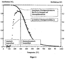
- Figure 2 shows the measured nitrogen oxide storage capabilities of the catalyst depending on the temperature of the synthesis gas.
- the thermal damage to the Nitrogen oxide storage material manifests itself in a sharp decrease in nitrogen oxide storage capacity at temperatures below 350 ° C. At higher temperatures the damage to the catalytically active components has no significant influence on nitrogen oxide storage capacity.
- the sulfurization of the Nitric oxide storage material decreases the overall nitrogen oxide storage capacity Temperature range between 250 and 500 ° C.
- FIGS. 3 to 5 show an exhaust gas cleaning system (1) with different probe configurations for carrying out the method according to the invention in accordance with the table.
- (2) denotes the storage catalytic converter, the function of which is to be checked regularly. It is installed in a housing of the exhaust gas cleaning system.
- probe 1 denotes a probe that measures a physical property of the catalyst, such as its complex impedance.
- the position of the probe 1 in FIG. 3 is exemplary and can be applied radially and axially over the entire catalytic converter or in several places of the catalytic converter.
- FIG. 4 shows an arrangement with a nitrogen oxide probe (probe 2) behind the catalytic converter, while FIG.
- lambda jump probes for example, two lambda jump probes, one of which is arranged in front of the catalytic converter and one behind the catalytic converter.
- lambda jump probes lambda linear probes, hydrogen probes, hydrocarbon probes and carbon monoxide probes can be used in this arrangement.
- the time differences ⁇ t 1 and ⁇ t 2 are measured.
- the probe arranged in front of the catalytic converter is used to determine the point in time at which the air ratio of the exhaust gas switches from lean to rich, or from rich to lean.
- the probe in front of the catalytic converter can be dispensed with if the switchover point is taken from the engine control.
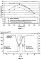
- FIG. 6 shows the course of the measured by a lambda linear probe Engine electronics imprinted air number in front of the storage catalytic converter as well as the probe voltages the jump probe 3 before the catalyst and the jump probe 4 behind the Catalyst.
- the air ratio has a value above 1 during the majority of the operation (here 1.4).
- nitrogen oxides are released by the nitrogen oxide storage function of the catalyst and oxygen through the oxygen storage function of the catalyst stored on the catalyst.
- the nitrogen oxide storage of the catalytic converter is full and it must be regenerated.
- the air ratio from the engine control to one Lowered value below 1 (here 0.75). Accordingly, the signal from probe 3 changes before corresponding to the catalyst. Due to the now reducing exhaust gas decomposed and desorbed nitrogen oxides stored on the storage catalyst and the oxygen stored on the catalyst for the oxidation of the reductive components of the exhaust gas consumed. It is only after the storage materials have been regenerated a breakthrough of the rich exhaust gas through the catalyst and accordingly to one corresponding increase in the signal of the probe 4.
- the two front edges of the probe signals show a time offset .DELTA.t 1 , which is caused by the nitrogen oxide storage capacity and possibly the oxygen storage capacity of the catalyst. The more the memory functions are damaged, the shorter the time offset ⁇ t 1 .
- probe 4 After completion of the regeneration phase, the air ratio is raised again to a value above 1, which means that the probe voltage of probe 3 jumps back to zero. However, probe 4 still shows a substoichiometric air number behind the catalytic converter for a certain time, since the oxygen from the lean exhaust gas is first used to replenish the oxygen storage of the catalytic converter before it can pass through the catalytic converter unhindered and the signal from probe 4 in its Initial state returns. As a result, a time offset ⁇ t 2 occurs between the two rear edges of the probe signals.
- the time offset ⁇ t 2 is only dependent on the oxygen storage capacity of the catalyst. By measuring this time, a judgment can thus be made about the state of the oxygen storage function of the catalytic converter. The lower the ⁇ t 2 , the lower the remaining oxygen storage capacity of the catalyst.
Landscapes
- Engineering & Computer Science (AREA)
- Chemical & Material Sciences (AREA)
- Combustion & Propulsion (AREA)
- Mechanical Engineering (AREA)
- General Engineering & Computer Science (AREA)
- Chemical Kinetics & Catalysis (AREA)
- Health & Medical Sciences (AREA)
- Emergency Medicine (AREA)
- Exhaust Gas After Treatment (AREA)
- Exhaust Gas Treatment By Means Of Catalyst (AREA)
- Measuring Oxygen Concentration In Cells (AREA)
- Investigating Or Analyzing Materials By The Use Of Electric Means (AREA)
- Combined Controls Of Internal Combustion Engines (AREA)
- Investigating Or Analysing Materials By The Use Of Chemical Reactions (AREA)
- Investigating Or Analyzing Non-Biological Materials By The Use Of Chemical Means (AREA)
- Catalysts (AREA)
Abstract
Description
Die vorliegende Erfindung betrifft ein Verfahren zur Überprüfung der Funktionstüchtigkeit eines Stickoxid-Speicherkatalysators, welcher für die Entfernung der im Abgasstrom eines Magermotors enthaltenen Stickoxide eingesetzt wird und wenigstens ein Stickoxid-Speichermaterial, eine katalytisch aktive Komponente und gegebenenfalls ein Sauerstoff-Speichermaterial enthält, wobei der Magermotor mit zyklischem Wechsel des Luft/Kraftstoff-Gemisches von mager nach fett betrieben wird und die im Abgas enthaltenen Stickoxide bei magerem Abgas vom Stickoxid-Speichermaterial gespeichert (Speicherphase) und bei fettem Abgas desorbiert und umgesetzt werden (Regenerationsphase).The present invention relates to a method for checking the functionality a nitrogen oxide storage catalytic converter, which is used for the removal of the in the exhaust gas stream of a lean-burn nitrogen oxide is used and at least one Nitric oxide storage material, a catalytically active component and optionally one Contains oxygen storage material, the lean engine with cyclical change of the air / fuel mixture is operated from lean to rich and in the exhaust gas nitrogen oxides contained in the lean exhaust gas stored by the nitrogen oxide storage material (Storage phase) and desorbed and converted in the case of rich exhaust gas (regeneration phase).
Stickoxid-Speicherkatalysatoren wurden speziell für die Abgasreinigung von mager betriebenen Brennkraftmaschinen entwickelt. Zur Klasse der mager betriebenen Brennkraftmaschinen gehören Dieselmotoren und mager betriebene Benzinmotoren. Beide Motortypen werden im folgenden als Magermotoren bezeichnet. Magermotoren, insbesondere Benzinmotoren mit Direkteinspritzung, werden zunehmend im Kraftfahrzeugbau eingesetzt, da sie eine theoretische Kraftstoffersparnis von bis zu 25% gegenüber stöchiometrisch betriebenen Brennkraftmaschinen ermöglichen.Nitrogen oxide storage catalytic converters were specially developed for lean exhaust gas cleaning operated internal combustion engines developed. To the class of lean-burn internal combustion engines include diesel engines and lean gasoline engines. Both Engine types are referred to below as lean engines. Lean engines, in particular Gasoline engines with direct injection are increasingly used in motor vehicle construction used, as compared to a theoretical fuel saving of up to 25% enable stoichiometrically operated internal combustion engines.
Stickoxid-Speicherkatalysatoren besitzen die Fähigkeit, in einem weiten Temperaturbereich Stickoxide unter oxidierenden Abgasbedingungen, das heißt im Magerbetrieb, zu speichern. Diese Betriebsphase wird daher im folgenden auch als Speicherphase bezeichnet.Nitrogen oxide storage catalysts have the ability to operate in a wide temperature range Nitrogen oxides under oxidizing exhaust gas conditions, i.e. in lean operation to save. This operating phase is therefore also referred to below as the storage phase.
Da die Speicherkapazität eines Speicherkatalysators begrenzt ist, muß er von Zeit zu Zeit regeneriert werden. Hierzu wird die Luftzahl des dem Motor zugeführten Luft/Kraftstoff-Gemisches und damit auch die Luftzahl des den Motor verlassenden Abgases für kurze Zeit auf Werte unter 1 abgesenkt. Dies wird auch als Anfettung des Luft/Kraftstoff-Gemisches oder des Abgases bezeichnet. Während dieser kurzen Betriebsphase liegen also im Abgas vor Eintritt in den Speicherkatalysator reduzierende Bedingungen vor.Since the storage capacity of a storage catalytic converter is limited, it has to be used from time to time Time to be regenerated. For this purpose, the air ratio of the engine is fed Air / fuel mixture and thus also the air ratio of the person leaving the engine Exhaust gas reduced to values below 1 for a short time. This is also called the enrichment of the Air / fuel mixture or the exhaust gas. During this short phase of operation are therefore reducing in the exhaust gas before entering the storage catalytic converter Conditions.
Unter den reduzierenden Bedingungen während der Anfettungsphase werden die gespeicherten Stickoxide freigesetzt und am Speicherkatalysator unter gleichzeitiger Oxidation von Kohlenmonoxid, Kohlenwasserstoffen und Wasserstoff wie bei konventionellen Dreiweg-Katalysatoren zu Stickstoff reduziert. Diese Betriebsphase des Speicherkatalysators wird im folgenden auch als Regenerationsphase bezeichnet. Bei korrekter Funktion des Gesamtsystems aus Speicherkatalysator, Sauerstoff-Sensoren und Motorelektronik liegen hinter dem Speicherkatalysator während der Regenerationsphase in etwa stöchiometrische Bedingungen vor, das heißt die vor dem Speicherkatalysator während der Regenerationsphase im Überschuß vorliegenden Kohlenwasserstoffe und Kohlenmonoxid werden am Speicherkatalysator durch die freigesetzten Stickoxide oxidiert. Erst nach Abschluss der Regeneration kommt es zu einem plötzlichen Anstieg der reduktiven Komponenten hinter dem Katalysator. Dies wird als Durchbruch der reduktiven Komponenten durch den Speicherkatalysator bezeichnet.Under the reducing conditions during the enrichment phase, the saved ones Nitrogen oxides released and on the storage catalytic converter with simultaneous oxidation of carbon monoxide, hydrocarbons and hydrogen as with conventional ones Three-way catalysts reduced to nitrogen. This operating phase of the storage catalytic converter is also referred to below as the regeneration phase. If correct Function of the overall system consisting of storage catalytic converter, oxygen sensors and Engine electronics are behind the storage catalytic converter during the regeneration phase roughly stoichiometric conditions, that is, before the storage catalytic converter hydrocarbons present in excess during the regeneration phase and Carbon monoxide is oxidized on the storage catalytic converter by the released nitrogen oxides. Only after the regeneration is completed there is a sudden increase in reductive components behind the catalyst. This is called the breakthrough of reductive Components designated by the storage catalytic converter.
Typischerweise beträgt die Dauer der Speicherphase etwa 30 bis 100 Sekunden. Die Dauer der Regenerationsphase ist wesentlich kürzer und liegt nur im Bereich von wenigen Sekunden (1 bis 20 Sekunden).The duration of the storage phase is typically about 30 to 100 seconds. The The duration of the regeneration phase is much shorter and is only in the range of a few Seconds (1 to 20 seconds).
Funktionsweise und Zusammensetzung von Stickoxid-Speicherkatalysatoren sind zum
Beispiel aus der EP 0 560 991 B1 bekannt. Als Speichermaterial enthalten diese Katalysatoren
wenigstens eine Komponente aus der Gruppe der Alkalimetalle (z.B. Kalium,
Natrium, Lithium, Cäsium), der Erdalkalimetalle (z.B. Barium, Calcium) oder der Seltenerdmetalle
(z.B. Lanthan, Yttrium). Als katalytisch aktives Element enthält der Speicherkatalysator
Platin. Unter oxidierenden Abgasbedingungen, das heißt im Magerbetrieb,
können die Speichermaterialien die im Abgas enthaltenen Stickoxide in Form von
Nitraten speichern. Hierzu ist es jedoch erforderlich, dass die Stickoxide, welche je nach
Bauart des Motors und seiner Betriebsweise zu etwa 60 bis 95 % aus Stickstoffmonoxid
bestehen, zunächst zu Stickstoffdioxid oxidiert werden. Dies geschieht an der Platinkomponente
des Speicherkatalysators.Functionality and composition of nitrogen oxide storage catalysts are for
Example known from
Neben den genannten Komponenten kann der Stickoxid-Speicherkatalysator noch Sauerstoff speichernde Komponenten enthalten. Er kann in diesem Fall neben der Stickoxidspeicherung auch Funktionen eines konventionellen Dreiweg-Katalysators übernehmen. Als Sauerstoff speichernde Komponente wird zum größten Teil Ceroxid eingesetzt. Der Stickoxid-Speicherkatalysator besitzt dann neben seiner Stickoxid-Speicherfunktion auch eine Sauerstoff-Speicherfunktion, er ist somit bifunktional.In addition to the components mentioned, the nitrogen oxide storage catalytic converter can also contain oxygen storing components included. In this case, he can next to the Nitrogen oxide storage also functions as a conventional three-way catalytic converter take. For the most part, cerium oxide is used as the oxygen-storing component used. The nitrogen oxide storage catalytic converter then has, in addition to its nitrogen oxide storage function also an oxygen storage function, it is therefore bifunctional.
Ein wichtiges Problem bei modernen Abgasreinigungsverfahren ist die Überprüfung der korrekten Funktion der verwendeten Katalysatoren, um einen rechtzeitigen Austausch von nicht mehr funktionstüchtigen Katalysatoren zu ermöglichen. Dies gilt auch für Stickoxid-Speicherkatalysatoren, bei denen verschiedene Alterungsmechanismen beobachtet werden. Sie können zum einen durch den im Kraftstoff vorhandenen Schwefel und zum anderen durch thermische Überlastung in ihrer Stickoxid-Speicherfähigkeit geschädigt werden. Während die Vergiftung durch Schwefel in der Regel durch Regeneration bei erhöhten Temperaturen wieder rückgängig gemacht werden kann, handelt es sich bei der thermischen Schädigung um einen irreversiblen Vorgang.An important problem with modern exhaust gas purification processes is the verification of the correct functioning of the catalysts used to ensure timely replacement of non-functional catalysts. This also applies to Nitric oxide storage catalysts, in which various aging mechanisms are observed become. On the one hand, they can be caused by the sulfur present in the fuel and secondly due to thermal overload in their nitrogen oxide storage capacity be harmed. During sulfur poisoning usually through regeneration can be reversed at elevated temperatures the thermal damage is an irreversible process.
Bei bifunktionalen Speicherkatalysatoren können prinzipiell beide Speicherfunktionen (Stickoxid und Sauerstoff) durch Vergiftung und thermische Einflüsse geschädigt werden. Dabei bedingt die Schädigung der einen Funktion nicht notwendigerweise die Schädigung der anderen Funktion. Da Stickoxide und Sauerstoff beides oxidierende Komponenten sind, lassen sich ihre Wirkungen nicht klar voneinander trennen, so dass es zu Fehldiagnosen bei der Prüfung des Katalysators kommen kann.With bifunctional storage catalytic converters, both storage functions can in principle (Nitrogen oxide and oxygen) can be damaged by poisoning and thermal influences. The damage to one function does not necessarily result in the Damage to the other function. Because nitrogen oxides and oxygen are both oxidizing Components, their effects cannot be clearly separated, so that misdiagnosis can occur when testing the catalytic converter.
Aus der DE 198 16 175 A1 ist ein Verfahren zur Überprüfung der Funktionstüchtigkeit eines Stickoxid-Speicherkatalysators bekannt, welches es gestattet, die Sauerstoff-Speicherfunktion und die Stickoxid-Speicherfunktion des Katalysators getrennt zu beurteilen. Zur Überprüfung der Funktionstüchtigkeit des Speicherkatalysators wird gemäß dieser Offenlegungsschrift die Luftzahl des Abgases von mager nach fett umgeschaltet und der zwischen dem ersten Umschalten bis zum Durchbruch des fetten Abgases durch den Katalysator sich ergebende Zeitversatz Δt1 sowie der nach erneutem Umschalten des Abgases von fett nach mager sich ergebende Zeitversatz Δt2 zwischen dem zweiten Umschalten und dem Durchbruch des Sauerstoffs durch den Katalysator gemessen. Die Zeitdifferenzen Δt1 und Δt2 erlauben die getrennte Beurteilung der Sauerstoff-Speicherfunktion und der Stickoxid-Speicherfunktion des Katalysators.From DE 198 16 175 A1 a method for checking the functionality of a nitrogen oxide storage catalytic converter is known, which allows the oxygen storage function and the nitrogen oxide storage function of the catalytic converter to be assessed separately. In order to check the functionality of the storage catalytic converter, the air ratio of the exhaust gas is switched from lean to rich and the time offset Δt 1 that results between the first changeover to the breakthrough of the rich exhaust gas by the catalytic converter and that after renewed switching of the exhaust gas from rich to lean resulting time offset .DELTA.t 2 measured between the second switching and the breakthrough of oxygen through the catalyst. The time differences Δt 1 and Δt 2 allow the oxygen storage function and the nitrogen oxide storage function of the catalytic converter to be assessed separately.
Die Stickoxid-Speicherfunktion des Katalysators hängt vom Stickoxid-Speichermaterial und von der katalytisch aktiven Komponente ab, in der Regel Platin. Sowohl das Stickoxid-Speichermaterial als auch die katalytisch aktive Komponente können geschädigt werden.The nitrogen oxide storage function of the catalyst depends on the nitrogen oxide storage material and on the catalytically active component, usually platinum. Both that Nitric oxide storage material as well as the catalytically active component can be damaged become.
Das Stickoxid-Speichermaterial speichert das im Abgas enthaltene Schwefeldioxid in Form von Sulfaten. Dies geht zu Lasten der Stickoxid-Speicherfähigkeit. Die Sulfate des Speichermaterials sind wesentlich stabiler als die Nitrate. Sie können jedoch bei Abgastemperaturen oberhalb von 600° C und unter reduzierenden Bedingungen wieder zersetzt werden. Durch diese Desulfatisierung erhält das Stickoxid-Speichermaterial weitgehend seine ursprüngliche Stickoxid-Speicherfähigkeit zurück. The nitrogen oxide storage material stores the sulfur dioxide contained in the exhaust gas Form of sulfates. This affects the nitrogen oxide storage capacity. The sulfates of the storage material are much more stable than the nitrates. However, you can at Exhaust gas temperatures above 600 ° C and under reducing conditions again be decomposed. This desulphation preserves the nitrogen oxide storage material largely returned to its original nitrogen oxide storage capacity.
Die Stickoxid-Speicherfähigkeit des Speichermaterials hängt entscheidend von seiner spezifischen Oberfläche ab, mit der es mit dem Abgas in Wechselwirkung treten kann. Wird das Speichermaterial Abgastemperaturen oberhalb etwa 800° C ausgesetzt, so verringert sich seine spezifische Oberfläche irreversibel und seine Stickoxid-Speicherfähigkeit nimmt ab.The nitrogen oxide storage capacity of the storage material depends crucially on its specific surface with which it can interact with the exhaust gas. If the storage material is exposed to exhaust gas temperatures above approximately 800 ° C, then its specific surface area decreases irreversibly and its nitrogen oxide storage capacity decreases.
Zur optimalen Nutzung der katalytisch aktiven Komponente ist sie auf den oxidischen Materialien des Speicherkatalysators in hochdisperser Form mit mittleren Partikelgrößen zwischen etwa 2 und 15 nm aufgebracht. Aufgrund der feinen Verteilung besitzen die Platinpartikel eine hohe Oberfläche für die Wechselwirkung mit den Bestandteilen des Abgases. Besonders im mageren Abgas von Magermotoren wird mit steigender Abgastemperatur eine irreversible Vergrößerung zum Beispiel der Platinkristallite beobachtet, die mit einer irreversiblen Verminderung der katalytischen Aktivität einhergeht.For optimal use of the catalytically active component, it is on the oxidic Storage catalyst materials in highly disperse form with medium particle sizes applied between about 2 and 15 nm. Own because of the fine distribution the platinum particles have a high surface area for interaction with the components of the exhaust gas. Especially in the lean exhaust gas from lean-burn engines increases with Exhaust gas temperature observed an irreversible increase, for example of the platinum crystallites, which is accompanied by an irreversible decrease in catalytic activity.
Mit dem Verfahren gemäß der DE 198 16 175 A1 wird eine mögliche Schädigung des Stickoxid-Speichermaterials als auch der katalytisch aktiven Komponente gleichzeitig erfasst. Eine separate Beurteilung der Schädigung des Speichermaterials von einer Schädigung der katalytisch aktiven Komponente ist mit diesem Verfahren nicht möglich. Eine getrennte Beurteilung der katalytisch aktiven Komponente ist jedoch wünschenswert, da ein Speicherkatalysator, dessen katalytische aktive Komponente bezüglich der Oxidation von Stickstoffmonoxid thermisch geschädigt ist, immer noch eine ausreichende Aktivität für die Abgasreinigung unter stöchiometrischen Abgasbedingungen aufweist.With the method according to DE 198 16 175 A1, possible damage to the Nitric oxide storage material and the catalytically active component at the same time detected. A separate assessment of the damage to the storage material from one Damage to the catalytically active component is not possible with this method. However, a separate assessment of the catalytically active component is desirable since a storage catalyst, the catalytic active component of which the oxidation of nitrogen monoxide is thermally damaged, still one sufficient activity for exhaust gas cleaning under stoichiometric exhaust gas conditions having.
Es ist daher Aufgabe der vorliegenden Erfindung, ein Verfahren anzugeben, welches neben der Beurteilung der Speichermaterialien des Speicherkatalysators auch in der Lage ist, eine mögliche Schädigung der katalytisch aktiven Komponente des Speicherkatalysators zu erkennen.It is therefore an object of the present invention to provide a method which in addition to the assessment of the storage materials of the storage catalyst also in the Is capable of possible damage to the catalytically active component of the storage catalyst to recognize.
Diese Aufgabe wird gelöst durch ein Verfahren zur Überprüfung der Funktionstüchtigkeit eines Stickoxid-Speicherkatalysators, welcher für die Entfernung der im Abgasstrom eines Magermotors enthaltenen Stickoxide eingesetzt wird und wenigstens ein Stickoxid-Speichermaterial, eine katalytisch aktive Komponente und gegebenenfalls ein Sauerstoff-Speichermaterial enthält, wobei der Magermotor mit zyklischem Wechsel des Luft/Kraftstoff-Gemisches von mager nach fett betrieben wird und die im Abgas enthaltenen Stickoxide bei magerem Abgas vom Stickoxid-Speichermaterial gespeichert (Speicherphase) und bei fettem Abgas desorbiert und umgesetzt werden (Regenerationsphase). Das Verfahren ist dadurch gekennzeichnet, dass zur Ermittlung einer möglichen Schädigung der katalytisch aktiven Komponente die Stickoxid-Speicherfähigkeit des Stickoxid-Speicherkatalysators bei Abgastemperaturen bestimmt wird, die in einem Bereich liegen, in dem die Oxidation von Stickstoffmonoxid zu Stickstoffdioxid kinetisch kontrolliert ist, während im thermodynamisch kontrollierten Bereich keine Änderung der Stickoxid-Speicherfähigkeit festzustellen ist, und dass zur Ermittlung einer möglichen Schädigung der Speichermaterialien die Stickoxid-Speicherfähigkeit des Stickoxid-Speicherkatalysators bei Abgastemperaturen bestimmt wird, die in einem Bereich liegen, in dem die Oxidation von Stickstoffmonoxid zu Stickstoffdioxid thermodynamisch kontrolliert ist.This problem is solved by a method for checking the functionality a nitrogen oxide storage catalytic converter, which is used for the removal of the in the exhaust gas stream of a lean-burn nitrogen oxide is used and at least one Nitric oxide storage material, a catalytically active component and optionally one Contains oxygen storage material, the lean engine with cyclical change of the air / fuel mixture is operated from lean to rich and in the exhaust gas nitrogen oxides contained in the lean exhaust gas stored by the nitrogen oxide storage material (Storage phase) and desorbed and converted in the case of rich exhaust gas (regeneration phase). The method is characterized in that for determining a possible Damage to the catalytically active component, the nitrogen oxide storage capacity of the nitrogen oxide storage catalyst is determined at exhaust gas temperatures, which in a Range in which the oxidation of nitrogen monoxide to nitrogen dioxide is kinetic is controlled, while in the thermodynamically controlled area no change the nitrogen oxide storage capacity is to be determined, and that to determine a possible damage to the storage materials the nitrogen oxide storage capacity of the Nitrogen oxide storage catalytic converter is determined at exhaust gas temperatures in a Range in which the oxidation of nitrogen monoxide to nitrogen dioxide is thermodynamic is checked.
Wenn im Rahmen dieser Erfindung von den Komponenten des Speicherkatalysators in der Einzahl gesprochen wird, so geschieht das aus Gründen der besseren Verständlichkeit. Für den Fachmann versteht es sich von selbst, dass zur Optimierung der Eigenschaften des Speicherkatalysators verschiedene Stickoxid-Speichermaterialien als auch Sauerstoff-Speichermaterialien und mehrere katalytisch aktive Komponenten (zum Beispiel Platin, Palladium, Rhodium, Iridium) miteinander kombiniert werden können.If in the context of this invention of the components of the storage catalyst in the singular is spoken, this is done for reasons of better intelligibility. For the expert it goes without saying that to optimize the properties of the storage catalyst various nitrogen oxide storage materials as well Oxygen storage materials and several catalytically active components (for example Platinum, palladium, rhodium, iridium) can be combined.
Das erfindungsgemäße Verfahren beruht auf den im folgenden darzulegenden Überlegungen zur Wirkungsweise von Stickoxid-Speicherkatalysatoren.The method according to the invention is based on the considerations to be set out below on the mode of action of nitrogen oxide storage catalysts.
Nach den anerkannten Theorien von Stickoxid-Speicherkatalysatoren werden die Stickoxide des Abgases in Form von Nitraten des Speichermaterials auf dem Katalysator gebunden. Allerdings reagiert nur Stickstoffdioxid mit dem Speichermaterial zu den entsprechenden Nitraten. Da etwa 60 bis 95 Vol.-% der Stickoxide im Abgas von Verbrennungsmotoren aus Stickstoffmonoxid bestehen, muss dieses erst an den katalytisch aktiven Komponenten des Speicherkatalysators zu Stickstoffdioxid oxidiert werden, bevor es mit dem Speichermaterial zu Nitraten reagieren kann.According to the accepted theories of nitrogen oxide storage catalysts, the Nitrogen oxides of the exhaust gas in the form of nitrates of the storage material on the catalyst bound. However, only nitrogen dioxide reacts with the storage material corresponding nitrates. Since about 60 to 95 vol .-% of nitrogen oxides in the exhaust gas of internal combustion engines consist of nitrogen monoxide, this must first be catalytically active components of the storage catalytic converter are oxidized to nitrogen dioxide, before it can react with the storage material to form nitrates.
Die Stickoxid-Speicherfähigkeit eines Speicherkatalysators wird also durch zwei Prozesse
bestimmt:
Bei der Oxidation von Stickstoffmonoxid in einer Sauerstoff enthaltenden Atmosphäre an den katalytisch aktiven Komponenten gemäß der Reaktionsgleichung (1) stellt sich in Abhängigkeit von der Temperatur jeweils ein bestimmtes Gleichgewicht zwischen Stickstoffmonoxid und Sauerstoff auf der einen Seite und Stickstoffdioxid auf der anderen Seite ein. Oberhalb einer Temperatur von etwa 300° C entspricht das sich einstellende Gleichgewicht dem thermodynamischen Gleichgewicht, das heißt das Gleichgewicht verschiebt sich wegen der stark exothermen Natur der Bildung von Stickstoffdioxid aus Stickstoffmonoxid und Sauerstoff mit zunehmender Temperatur nach links. Oberhalb von etwa 650° C reagiert Stickstoffmonoxid nur noch in sehr geringem Umfang mit Sauerstoff zu Stickstoffdioxid. Unterhalb von 300° C verschiebt sich das thermodynamische Gleichgewicht gemäß Reaktionsgleichung (1) mit abnehmender Temperatur nach rechts, das heißt die Bildung von Stickstoffdioxid ist in diesem Temperaturbereich thermodynamisch begünstigt. Trotzdem nimmt unterhalb von etwa 300° C die Bildung von Stickstoffdioxid aufgrund kinetischer Beschränkungen wieder ab und ist unterhalb von 100° C vernachlässigbar. Die hier genannte Temperaturgrenze von etwa 300° C gilt für einen Sauerstoffgehalt der Gasmischung von 6 Vol.-%.Oxidation of nitrogen monoxide in an atmosphere containing oxygen on the catalytically active components according to reaction equation (1) depending on the temperature a certain balance between Nitric oxide and oxygen on one side and nitrogen dioxide on the other Side one. Above a temperature of around 300 ° C, this corresponds to Balance the thermodynamic balance, that is, the balance shifts because of the highly exothermic nature of nitrogen dioxide formation from nitrogen monoxide and oxygen with increasing temperature to the left. Above about 650 ° C, nitrogen monoxide reacts only to a very small extent with oxygen to nitrogen dioxide. The thermodynamic shifts below 300 ° C Equilibrium according to reaction equation (1) with decreasing temperature to the right, that is, the formation of nitrogen dioxide is in this temperature range thermodynamically favored. Nevertheless, below about 300 ° C Formation of nitrogen dioxide due to kinetic restrictions and is negligible below 100 ° C. The temperature limit of about 300 ° C applies to an oxygen content of 6% by volume of the gas mixture.
In der praktischen Durchführung des Verfahrens wird die Messung im kinetisch kontrollierten Bereich unterhalb von 300° C und im thermodynamisch kontrollierten Bereich bevorzugt zwischen 350 und 450° C vorgenommen.In the practical implementation of the method, the measurement is kinetically controlled Range below 300 ° C and in the thermodynamically controlled range preferably between 350 and 450 ° C.
Die Stickoxid-Speicherfähigkeit des Katalysators ist im kinetisch kontrollierten Temperaturbereich stark von der zur Verfügung stehenden Oberfläche der Platinpartikel abhängig. Je größer die Platinoberfläche ist, um so weniger wirken sich kinetische Beschränkungen auf die Bildung des thermodynamisch begünstigten Stickstoffdioxids aus. Dagegen spielt die Platinoberfläche im thermodynamisch kontrollierten Bereich bei der Bildung von Stickstoffdioxid nur noch eine untergeordnete Rolle. Der entscheidende Faktor für die Stickoxid-Speicherfähigkeit ist in diesem Bereich eine schnelle Entfernung des gebildeten Stickstoffdioxids aus dem Gleichgewicht gemäß Reaktionsgleichung (1) durch Reaktion mit dem Speichermaterial zu Nitraten, was zu einer dem Gleichgewicht entsprechenden Neubildung von Stickstoffdioxid führt. Die Nitratbildung hängt von einer möglichen Schädigung des Speichermaterials durch thermische Einflüsse oder durch Schwefelvergiftung ab. The nitrogen oxide storage capacity of the catalyst is in the kinetically controlled temperature range strongly depends on the available surface of the platinum particles. The larger the platinum surface area, the less kinetic restrictions have an effect on the formation of thermodynamically favored nitrogen dioxide. In contrast, the platinum surface plays in the thermodynamically controlled area Formation of nitrogen dioxide only plays a subordinate role. The decisive one The factor for nitrogen oxide storage capacity in this area is rapid removal of the nitrogen dioxide formed from the equilibrium according to the reaction equation (1) by reaction with the storage material to give nitrates, resulting in one of the Equilibrium leads to the formation of new nitrogen dioxide. The nitrate formation depends on possible damage to the storage material by thermal Influences or by sulfur poisoning.
Durch Überprüfung der Stickoxid-Speicherfähigkeit des Katalysators in den beiden Temperaturbereichen (kinetisch kontrollierter Bereich und thermodynamisch kontrollierter Bereich der Bildung von Stickstoffdioxid) ist es daher möglich eine Schädigung der katalytisch aktiven Komponenten von einer Schädigung des Speichermaterials zu unterscheiden.By checking the nitrogen oxide storage capacity of the catalyst in the two Temperature ranges (kinetically controlled and thermodynamically controlled Area of formation of nitrogen dioxide) it is therefore possible for damage of the catalytically active components from damage to the storage material differ.
Zur Überprüfung der Stickoxid-Speicherfähigkeit können verschiedenartige Sensoren
eingesetzt werden. Es können sowohl Stickoxid-Sonden wie auch Lambda-Linearsonden,
Lambda-Sprungsonden, Kohlenwasserstoff-Sonden, Kohlenmonoxid-Sonden
oder Wasserstoff-Sonden eingesetzt werden. Weiterhin ist es möglich, die
Stickoxid-Speicherfähigkeit an Hand der Änderung einer von der Menge der gespeicherten
Stickoxide abhängigen physikalischen Eigenschaft des Speicherkatalysators zu
bestimmen. Besonders geeignet hierfür ist die komplexe Impedanz des Katalysators.
Ein Verfahren zur Bestimmung der Stickoxid-Speicherfähigkeit eines Speicherkatalysators
an Hand seiner komplexen Impedanz wird zum Beispiel in der EP 0 936 348 A2
beschrieben.Various types of sensors can be used to check the nitrogen oxide storage capacity
be used. Both nitrogen oxide probes and lambda linear probes,
Lambda jump probes, hydrocarbon probes, carbon monoxide probes
or hydrogen probes can be used. It is also possible to use the
Nitric oxide storage capacity based on changing one of the amount stored
Nitrogen oxide dependent physical property of the storage catalytic converter
determine. The complex impedance of the catalyst is particularly suitable for this.
A method for determining the nitrogen oxide storage capacity of a storage catalytic converter
based on its complex impedance, for example, in
Eine Stickoxid-Sonde ist in der Lage, die Stickoxid-Konzentration im Abgas direkt zu messen. Die verfügbaren Stickoxid-Sonden erzeugen aufgrund ihres Aufbaus gleichzeitig auch ein lineares und ein sprungartiges Signal für den Sauerstoffgehalt des Abgases (Lambdasignal).A nitrogen oxide probe is able to directly measure the nitrogen oxide concentration in the exhaust gas measure up. The available nitrogen oxide probes produce simultaneously due to their structure also a linear and a sudden signal for the oxygen content of the exhaust gas (Lambda signal).
Eine Lambda-Linearsonde liefert ein Sonden-Signal, das linear mit dem Sauerstoffgehalt des Abgases ansteigt. Eine Lambda-Sprungsonde liefert dagegen eine Sondenspannung, die nur zwei Zustände kennt. Bei Über- oder Unterschreiten eines Schwellwertes der Sauerstoffkonzentration im Abgas springt die Sondenspannung von einem Zustand in den anderen. Unter mageren Bedingungen ist die Sondenspannung praktisch gleich Null. Unter fetten Bedingungen zeigt die Sonde eine Ausgangsspannung die typischerweise zwischen 700 und 900 mV liegt. Die Sondenspannung besitzt einen steilen Gradienten im Übergangsbreich um Lambda = 1. Mit Hilfe dieses Sondentyps ist eine gute Erkennung von Durchbrüchen des fetten Abgases am Ende einer Regenerationsphase möglich. Die Funktionsweise der für das Verfahren geeigneten Lambda-Sonden werden im Kraftfahrttechnischen Taschenbuch von Bosch, VDI-Verlag, 20. Auflage von 1995, Seiten 490 bis 492, beschrieben.A lambda linear probe provides a probe signal that is linear with the oxygen content of the exhaust gas increases. In contrast, a lambda step probe supplies a probe voltage, that knows only two states. When a threshold value is exceeded or undershot the oxygen concentration in the exhaust gas jumps the probe voltage from one state in the others. Under lean conditions, the probe voltage is practically the same Zero. Under rich conditions, the probe typically shows an output voltage is between 700 and 900 mV. The probe voltage has a steep gradient in the transition range around lambda = 1. Using this type of probe is a good one Detection of breakthroughs of the rich exhaust gas at the end of a regeneration phase possible. The mode of operation of the lambda probes suitable for the method will be in the automotive engineering paperback by Bosch, VDI-Verlag, 20th edition from 1995, Pages 490 to 492.
Zur Bestimmung der Stickoxid-Speicherfähigkeit können auch Kohlenwasserstoff-, Kohlenmonoxid- und Wasserstoff-Sonden eingesetzt werden. Diese Sondentypen befinden sich derzeit in der Entwicklung und sind noch nicht serienreif. Auch mit diesen Sonden kann der Durchbruch des fetten Abgases durch den Katalysator am Ende der Regenerationsphase bestimmt werden.To determine the nitrogen oxide storage capacity, hydrocarbon, Carbon monoxide and hydrogen probes are used. These types of probes are located are currently in development and are not yet ready for series production. Even with these Probes can breakthrough the rich exhaust gas through the catalyst at the end of the Regeneration phase can be determined.
Bei Verwendung einer Stickoxid-Sonde ist es möglich, die Stickoxid-Speicherfähigkeit des Speicherkatalysators direkt zu bestimmen. Hierzu wird die Stickoxid-Sonde hinter dem Speicherkatalysator im Abgasstrom angeordnet. Übersteigt die Stickoxid-Konzentration während der Speicherphase einen vorgegebenen Schwellwert, so wird von der Motorsteuerung die Regeneration eingeleitet. Aus den in der Motorsteuerung abgelegten Kennfeldern ist es möglich, die bis zu diesem Zeitpunkt emittierte Menge der Stickoxide durch Integration über die durchlaufenen Betriebszustände des Motors zu berechnen und mit der Speicherkapazität des Katalysators im frischen Zustand zu vergleichen. Liegt die bis zum Erreichen des Schwellwertes aufsummierte Menge der Stickoxide wesentlich unter der Speicherkapazität des frischen Katalysators, so liegt eine Schädigung der Speicherfähigkeit vor. Die Zeitdauer vom Beginn einer Speicherphase bis zum Erreichen des Schwellenwertes für die Regeneration wird im folgenden mit Δts bezeichnet.When using a nitrogen oxide probe, it is possible to directly determine the nitrogen oxide storage capacity of the storage catalytic converter. For this purpose, the nitrogen oxide probe is arranged behind the storage catalytic converter in the exhaust gas stream. If the nitrogen oxide concentration exceeds a predefined threshold value during the storage phase, regeneration is initiated by the engine control. From the maps stored in the engine control, it is possible to calculate the amount of nitrogen oxides emitted up to this point by integrating them through the operating states of the engine and to compare them with the storage capacity of the catalytic converter in the fresh state. If the amount of nitrogen oxides added up until the threshold value is reached is substantially below the storage capacity of the fresh catalyst, the storage capacity is damaged. The time from the beginning of a storage phase until the threshold value for regeneration is reached is referred to below as Δt s .
Durch Wahl des Temperaturbereiches, in dem die Messung vorgenommen wird, kann unterschieden werden, welcher Art diese Schädigung ist. Eine Schädigung der katalytisch aktiven Komponente liegt vor, wenn im kinetisch kontrollierten Bereich bei Temperaturen des Abgases unterhalb von 300° C eine Verminderung der Stickoxid-Speicherfähigkeit festgestellt wird, während im thermodynamisch kontrollierten Bereich oberhalb von 300°C, bevorzugt im Temperaturbereich von 350 - 450° C, keine Änderung der Stickoxid-Speicherfähigkeit feststellbar ist.By selecting the temperature range in which the measurement is carried out a distinction is made between the types of this damage. A catalytic damage active component is present when in the kinetically controlled range at temperatures the exhaust gas below 300 ° C a reduction in nitrogen oxide storage capacity is detected while in the thermodynamically controlled area above 300 ° C, preferably in the temperature range of 350 - 450 ° C, none Change in nitrogen oxide storage capacity is noticeable.
Die Ermittlung einer möglichen Schädigung der Speichermaterialien wird bei Temperaturen des Abgases oberhalb von 300° C, bevorzugt im Temperaturbereich von 350 - 450° C, vorgenommen. Wird hierbei eine Schädigung festgestellt, so kann diese auf einer Verschwefelung beruhen oder in einer thermischen Schädigung des Speichermaterials bestehen. Im ersten Fall handelt es sich um eine reversible Schädigung, die durch Entschwefelung des Speichermaterials wieder rückgängig gemacht werden kann, im zweiten Fall handelt es sich um eine permanente Schädigung. Zur Unterscheidung dieser beiden Schädigungsmechanismen wird daher nach Erkennen einer Schädigung des Speichermaterials eine Desulfatierung des Stickoxid-Speicherkatalysators eingeleitet.The determination of possible damage to the storage materials is carried out at temperatures of the exhaust gas above 300 ° C, preferably in the temperature range of 350 - 450 ° C. If damage is found here, it can be caused by are caused by sulfurization or thermal damage to the storage material consist. In the first case, it is a reversible damage caused by Desulfurization of the storage material can be reversed in the the second case is permanent damage. To distinguish this Both damage mechanisms are therefore recognized after damage to the Storage material initiated a desulfation of the nitrogen oxide storage catalyst.
Mit Lambda-Sonden, Kohlenwasserstoff-, Kohlenmonoxid- und Wasserstoff-Sonden kann die Stickoxid-Speicherfähigkeit nur indirekt während der Regenerationsphase bestimmt werden. Diese Sonden werden dazu benutzt, um den Zeitversatz Δt1 zwischen dem Umschalten des Luft/Kraftstoff-Gemisches von mager nach fett und dem Durchbruch des fetten Abgases durch den Stickoxid-Speicherkatalysator zu messen. Diese Zeitdifferenz wird durch die Wirkung des Stickoxid-Speichermaterials und durch das gegebenenfalls vorliegende Sauerstoff-Speichermaterial des Katalysators verursacht. Die Zeitdifferenz wird um so kleiner, je geringer die Speicherfähigkeit des Katalysators für Stickoxide und gegebenenfalls Sauerstoff ist.With lambda probes, hydrocarbon, carbon monoxide and hydrogen probes, the nitrogen oxide storage capacity can only be determined indirectly during the regeneration phase. These probes are used to measure the time offset Δt 1 between the switching of the air / fuel mixture from lean to rich and the breakthrough of the rich exhaust gas through the nitrogen oxide storage catalytic converter. This time difference is caused by the action of the nitrogen oxide storage material and by the oxygen storage material of the catalyst which may be present. The smaller the storage capacity of the catalyst for nitrogen oxides and possibly oxygen, the smaller the time difference.
Sollen die Stickoxid-Speicherfähigkeit und die Sauerstoff-Speicherfähigkeit des Katalysators getrennt voneinander beurteilt werden, so muss nach erneutem Umschalten des Luft/Kraftstoff-Gemisches von fett nach mager der sich ergebende Zeitversatz Δt2 zwischen dem zweiten Umschalten und dem Durchbruch des Sauerstoffs durch den Katalysator gemessen werden. Dieser Zeitversatz ist nur noch abhängig von der Sauerstoff-Speicherfähigkeit des Katalysators.If the nitrogen oxide storage capacity and the oxygen storage capacity of the catalytic converter are to be assessed separately from one another, the resulting time offset Δt 2 between the second switching and the breakthrough of the oxygen through the catalytic converter must be carried out after the air / fuel mixture has been switched from rich to lean again be measured. This time offset is only dependent on the oxygen storage capacity of the catalytic converter.
Nach dem Umschalten der Luftzahl von mager nach fett werden die Stickoxide durch die reduktiven Komponenten des Abgases (Kohlenwasserstoffe, Kohlenmonoxid und Wasserstoff) desorbiert und am Speicherkatalysator umgesetzt. Außerdem werden die reduktiven Komponenten des Abgases unter Verbrauch des gespeicherten Sauerstoffs oxidiert. Stickoxid-Speichermaterial und Sauerstoff-Speichermaterial werden somit im fetten Abgas entleert.After switching the air ratio from lean to rich, the nitrogen oxides are released the reductive components of the exhaust gas (hydrocarbons, carbon monoxide and Desorbed hydrogen and implemented on the storage catalyst. In addition, the reductive components of the exhaust gas using the stored oxygen oxidized. Nitrogen oxide storage material and oxygen storage material are thus in the rich exhaust gas emptied.
Die Luftzahl des Abgases hinter dem Katalysator folgt der Luftzahländerung vor dem Katalysator nicht spontan, sondern nur mit einer gewissen Verzögerung und bleibt, solange die Speichermaterialien nicht entleert sind, noch im mageren Bereich, so dass eine hinter dem Katalysator angeordnete Sonde noch eine magere Abgaszusammensetzung melden würde. Erst wenn Stickoxid-Speichermaterial und Sauerstoff-Speichermaterial entleert sind, werden keine Kohlenwasserstoffe, Kohlenmonoxid und Wasserstoff mehr umgesetzt. Es kommt dann zum Durchbruch dieser Stoffe durch den Katalysator und die Luftzahl des Abgases hinter dem Katalysator wechselt in den fetten Bereich. Dieser Zeitpunkt kann in einfacher Weise mit den genannten Sonden bestimmt werden.The air ratio of the exhaust gas behind the catalytic converter follows the change in air ratio before Catalyst not spontaneously, but only with a certain delay and stays as long the storage materials are not empty, nor in the lean area, so a behind the catalyst still a lean exhaust gas composition would report. Only when nitrogen oxide storage material and oxygen storage material are emptied, hydrocarbons, carbon monoxide and hydrogen are no longer implemented. These substances then break through the catalyst and the air number of the exhaust gas behind the catalytic converter changes to the rich range. This The point in time can be determined in a simple manner using the probes mentioned.
Die gespeicherten Stickoxide werden in der Regel schneller freigesetzt als der auf dem Katalysator gespeicherte Sauerstoff durch die Kohlenwasserstoffe im fetten Abgas verbraucht, beziehungsweise entleert, wird. Außerdem sind diese Desorptionsgeschwindigkeiten noch von dem Grad der Anfettung des Abgases sowie der Abgastemperatur abhängig. Je stärker das Abgas angefettet wird, um so schneller werden Stickoxid-Speichermaterial und Sauerstoff-Speichermaterial entleert. Gleiches gilt für eine Erhöhung der Abgastemperatur. Für das erfindungsgemäße Verfahren kann die Luftzahl während der Fettphase in einem Intervall zwischen 0,7 und 0,99 festgelegt werden.The stored nitrogen oxides are usually released faster than that on the Catalyst stored oxygen consumed by the hydrocarbons in the rich exhaust gas, or emptied. In addition, these are desorption speeds the degree of enrichment of the exhaust gas and the exhaust gas temperature dependent. The more the exhaust gas is enriched, the faster nitrogen oxide storage material becomes and emptied oxygen storage material. The same applies to an increase the exhaust gas temperature. The air ratio can be used for the method according to the invention during the fat phase in an interval between 0.7 and 0.99.
Wird eine Luftzahl knapp unter 1 gewählt, so geht die Entleerung der Speicher langsamer vor sich als bei einem niedrigeren Wert der Luftzahl. Dies ermöglicht eine höhere Genauigkeit der Zeitmessung. Der Durchbruch der reduktiven Komponenten durch den Katalysator tritt in diesem Fall erst nach vollständiger Entleerung von Stickoxid-Speichermaterial und Sauerstoff-Speichermaterial ein, so dass die zu messende Zeitdifferenz Δt1 die Summe beider Speicherkapazitäten wiedergibt.If an air ratio just under 1 is selected, the emptying of the accumulator takes place more slowly than with a lower value of the air ratio. This enables a higher accuracy of the time measurement. In this case, the reductive components do not break through the catalyst until the nitrogen oxide storage material and oxygen storage material have been completely emptied, so that the time difference Δt 1 to be measured reflects the sum of both storage capacities.
Bevorzugt wird die Prüfung des Katalysators bei einem bestimmten Betriebszustand des Motors, das heißt bei definierter Abgastemperatur und Luftzahl während der Fettphase, beziehungsweise Regenerationsphase, vorgenommen.It is preferred to test the catalyst in a specific operating state of the Engines, i.e. at a defined exhaust gas temperature and air ratio during the rich phase, or regeneration phase.
Der Entleerung des Stickoxid- und Sauerstoffspeichers beim Umschalten der Luftzahl von mager nach fett steht eine entsprechende Auffüllung des Sauerstoffspeichers nach Beendigung der Fettphase gegenüber. Wie schon beim Umschalten von mager nach fett so folgt auch nach Umschalten von fett nach mager die Luftzahl hinter dem Katalysator nicht spontan der Luftzahl vor dem Katalysator. Die Luftzahl bleibt zunächst im fetten Bereich, da der Sauerstoffüberschuß des mageren Abgases jetzt erst zur Auffüllung des Sauerstoffspeichers verwendet wird. Eine hinter dem Katalysator angeordnete Sprung-Lambda-Sonde würde also weiterhin ein fettes Abgas anzeigen. Erst nach Auffüllung des Sauerstoffspeichers kommt es zu einem merklichen Durchbruch des Sauerstoffs durch den Katalysator und damit im Falle einer Messung mit einer Sprungsonde zu einem Sprung des Sondensignals. Die meßbare Zeitdifferenz Δt2 zwischen dem Beendigen der Fettphase und dem Durchbruch des Sauerstoffs durch den Katalysator ist ein Maß für die Speicherkapazität des Sauerstoffspeichers. Sinkt die Sauerstoff-Speicherkapazität des Katalysators durch Vergiftung mit Schwefel oder durch thermische Schädigung, so macht sich dies durch eine Verringerung von Δt2 bemerkbar und es kann gegebenenfalls ein Signal zum Austausch des Katalysators gesetzt werden.The emptying of the nitrogen oxide and oxygen storage when switching the air ratio from lean to rich is countered by a corresponding filling of the oxygen storage after the end of the rich phase. As when switching from lean to rich, the air ratio behind the catalytic converter does not spontaneously follow the air ratio before the catalytic converter even after switching from rich to lean. The air ratio initially remains in the rich range, since the excess of oxygen in the lean exhaust gas is now only used to fill up the oxygen reservoir. A jump lambda probe arranged behind the catalytic converter would therefore continue to display a rich exhaust gas. Only after the oxygen storage has been filled does the oxygen break through the catalyst appreciably and thus, in the case of a measurement with a step probe, the probe signal jumps. The measurable time difference Δt 2 between the termination of the fat phase and the breakthrough of the oxygen through the catalyst is a measure of the storage capacity of the oxygen store. If the oxygen storage capacity of the catalyst drops due to sulfur poisoning or thermal damage, this is noticeable by a reduction in Δt 2 and a signal for replacing the catalyst can be set if necessary.
Zur getrennten Beurteilung der Stickoxid-Speicherfähigkeit und der Sauerstoff-Speicherfähigkeit
können für Δt1 und Δt2 folgende Beziehungen aufgestellt werden:
Die Proportionalitätskonstante b beschreibt die Entleerungsgeschwindigkeit des Sauerstoffspeichers,
während die Konstante c ein Maß für die Geschwindigkeit ist, mit der
der Sauerstoffspeicher wieder aufgefüllt wird. Aus den Beziehungen (2) und (3) ergibt
sich für die Kapazität des Stickoxidspeichers:
Das Verhältnis b/c in Gleichung (4) ist vom Material und den gewählten Betriebsbedingungen des Motors während der Katalysatorprüfung abhängig. Es kann in Vorversuchen ermittelt werden. Gleichungen (2) und (3) ermöglichen also auch bei gleichzeitiger Anwesenheit einer Stickoxid-Speicherfunktion und einer Sauerstoff-Speicherfunktion im Speicherkatalysator die getrennte Beurteilung beider Funktionen durch Messung von Δt1 und Δt2.The ratio b / c in equation (4) depends on the material and the selected operating conditions of the engine during the catalyst test. It can be determined in preliminary tests. Equations (2) and (3) thus enable the separate assessment of both functions by measuring Δt 1 and Δt 2 even when a nitrogen oxide storage function and an oxygen storage function are present in the storage catalytic converter at the same time.
Die Zeitdifferenzen Δt1 und Δt2 können auf verschiedenartige Weise bestimmt werden. So besteht die Möglichkeit, die Zeitdifferenzen Δt1 und Δt2 aus der Differenz des jeweiligen Zeitpunktes der Umschaltung der Luftzahl durch die Motorsteuerung und dem jeweiligen Zeitpunkt der Änderung der Luftzahl hinter dem Katalysator zu ermitteln. Bei langen Abgasleitungen zwischen Motor und Speicherkatalysator müssen die so bestimmten Zeitdifferenzen gegebenenfalls um die Laufzeiten des Abgases zwischen Motor und Katalysator korrigiert werden. Alternativ hierzu können zur Bestimmung der Zeitdifferenzen die Änderungen der Luftzahl vor und hinter dem Katalysator mit je einer Sonde ermittelt werden.The time differences Δt 1 and Δt 2 can be determined in various ways. It is thus possible to determine the time differences Δt 1 and Δt 2 from the difference between the respective point in time at which the air ratio is switched over by the engine control and the respective point in time at which the air ratio changes behind the catalytic converter. In the case of long exhaust gas lines between the engine and the storage catalytic converter, the time differences determined in this way may have to be corrected for the running times of the exhaust gas between the engine and the catalytic converter. Alternatively, the changes in the air ratio upstream and downstream of the catalytic converter can be determined with a probe to determine the time differences.
Tabelle 1 gibt einen Überblick über die mit dem erfindungsgemäßen Verfahren sich ergebenden Beurteilungsmöglichkeiten des Stickoxid-Speicherkatalysators bei Verwendung unterschiedlicher Sonden. Bezüglich der Sonden können zwei Gruppen unterschieden werden.Table 1 gives an overview of the method used by the invention Resulting assessment options of the nitrogen oxide storage catalyst when used different probes. Two groups can be distinguished with regard to the probes become.
Mit einer Stickoxid-Sonde oder einer Eigenschafts-Sonde für eine physikalische Eigenschaft
des Speicherkatalysators kann die Zeitdauer der Speicherphase Δts gemessen
werden. Die Messung kann sowohl im kinetisch (kin) als auch im thermodynamisch
(therm) kontrollierten Temperaturbereich vorgenommen werden. Wird eine Verringerung
von Δts im kinetisch kontrollierten Bereich festgestellt (![]()
![]()
Mit einer Sauerstoff-, Wasserstoff-, Kohlenwasserstoff- oder einer Kohlenmonoxid-Sonde
lassen sich die schon definierten Zeitdifferenzen Δt1 und Δt2 messen. Mit
Δt1,DeSOx, und Δt2,DeSOx werden in Tabelle 1 die Zeitdifferenzen Δt1 und Δt2 nach erfolgter
Desulfatisierung bezeichnet. Entsprechend den obigen Erläuterungen zu den Messungen
mit Stickoxid- oder Eigenschafts-Sonde ergeben sich die in Tabelle 1 aufgeführten
Unterscheidungsmöglichkeiten für die verschiedenen Schädigungsmechanismen
des Speicherkatalysators.

Die Erfindung wird nun an Hand der Beispiele 1 und 2 und der Figuren 1 und 5 näher erläutert. Es zeigen:
- Figur 1:
- Messungen zum Oxidationsgleichgewicht gemäß Reaktionsgleichung (1)
- Figur 2:
- Stickoxid-Speicherfähigkeit eines Speicherkatalysators im frischen Zustand und nach unterschiedlichen Schädigungen in Abhängigkeit von der Temperatur
- Figur 3:
- Abgasreinigungsanlage mit einer Sonde für eine physikalische Eigenschaft des Speicherkatalysators
- Figur 4:
- Abgasreinigungsanlage mit einer Stickoxid-Sonde hinter dem Speicherkatalysator
- Figur 5:
- Abgasreinigungsanlage mit einer Lambda-Sprungsonde vor und hinter dem Speicherkatalysator
- Figur 6:
- Zeitlicher Verlauf der aufgeprägten Luftzahl λ, vor dem Speicherkatalysator
und der Signalverlauf der beiden Lambda-
Sprungsonden von Figur 4 während der Überprüfung der Katalysatorfunktion
- Figure 1:
- Oxidation equilibrium measurements according to reaction equation (1)
- Figure 2:
- Nitrogen oxide storage capacity of a storage catalytic converter in the fresh state and after various damage depending on the temperature
- Figure 3:
- Exhaust gas cleaning system with a probe for a physical property of the storage catalytic converter
- Figure 4:
- Exhaust gas cleaning system with a nitrogen oxide probe behind the storage catalytic converter
- Figure 5:
- Exhaust gas cleaning system with a lambda jump probe in front of and behind the storage catalytic converter
- Figure 6:
- Time course of the impressed air number λ, upstream of the storage catalytic converter and the signal course of the two lambda jump probes from FIG. 4 during the check of the catalytic converter function
Es wurde die bei Oxidation von Stickstoffmonoxid an einem Oxidationskatalysator sich ergebende Gleichgewichtskonzentration von Stickstoffdioxid in Abhängigkeit von der Gastemperatur gemessen und mit der thermodynamisch berechneten Gleichgewichtskonzentration verglichen.It became the case of oxidation of nitrogen monoxide on an oxidation catalyst resulting equilibrium concentration of nitrogen dioxide depending on the Gas temperature measured and with the thermodynamically calculated equilibrium concentration compared.
Für diese Messungen wurde ein reiner Platin/Aluminiumoxid-Oxidationskatalysator angefertigt. Hierzu wurden 15 g Platin auf 700 g Aluminiumoxid mit einer BET-Oberfläche im calcinierten Frischzustand von 210 m2/g durch Imprägnieren mit einer wäßrigen Lösung von Platintetraamminnitrat sowie anschließendem Trocknen und Calcinieren bei 500° C an Luft abgeschieden.A pure platinum / alumina oxidation catalyst was made for these measurements. For this purpose, 15 g of platinum were deposited on 700 g of aluminum oxide with a BET surface in the calcined fresh state of 210 m 2 / g by impregnation with an aqueous solution of platinum tetraammine nitrate and subsequent drying and calcining at 500 ° C. in air.
Das auf diese Weise hergestellte Katalysator-Pulver wurden zu einer wäßrigen Dispersion angerührt und auf eine Partikelgröße von 3-5 µm (d50) gemahlen. Mit dieser Dispersion wurde ein handelsüblicher Wabenkörper aus Cordierit durch Eintauchen in die Dispersion beschichtet. The catalyst powder prepared in this way was stirred into an aqueous dispersion and ground to a particle size of 3-5 μm (d 50 ). A commercial honeycomb body made of cordierite was coated with this dispersion by immersing it in the dispersion.
Der beschichtete Wabenkörper wurde bei 120° C im Trockenschrank getrocknet. Tauch- und Trockenschritte wurden so lange wiederholt, bis eine Beladung von 110 g pro Liter Wabenkörpervolumen im trocknen Zustand erreicht war. Anschließend erfolgte eine 4-stündige Calcinierung des beschichteten Wabenkörpers bei 500° C. Der fertige Katalysator enthielt somit 107,7 g/l Aluminiumoxid und 2,3 g/l Platin.The coated honeycomb body was dried at 120 ° C. in a drying cabinet. Dipping and drying steps were repeated until a load of 110 g per liter of honeycomb body volume when dry. Then followed a 4-hour calcination of the coated honeycomb body at 500 ° C. The finished catalyst thus contained 107.7 g / l aluminum oxide and 2.3 g / l platinum.
Über den Katalysator wurde ein Gasgemisch aus 500 Vol.-ppm Stickstoffmonoxid, 6 Vol.-% Sauerstoff und Rest Stickstoff bei Temperaturen zwischen 50 und 500° C mit einer Raumgeschwindigkeit von 30000 h-1 geleitet. In Figur 1 sind die dabei hinter dem Katalysator gemessenen Gleichgewichtsanteile von Stickstoffdioxid über der Temperatur aufgetragen und mit den thermodynamisch berechneten Werten verglichen.A gas mixture of 500 ppm by volume of nitrogen monoxide, 6% by volume of oxygen and the rest of nitrogen was passed over the catalyst at temperatures between 50 and 500 ° C. at a space velocity of 30,000 h -1 . In Figure 1, the equilibrium proportions of nitrogen dioxide measured over the temperature behind the catalytic converter are plotted and compared with the thermodynamically calculated values.
Oberhalb von etwa 300° C stimmen die gemessenen Gleichgewichtswerte mit den für 6 Vol.-% Sauerstoff berechneten Werten sehr gut überein. Unterhalb von 300° C geht die gemessene Gleichgewichtskonzentration mit fallender Temperatur wegen kinetischer Beschränkungen der Reaktion bis auf Null zurück, während die berechnete Gleichgewichtskonzentration bei tiefen Temperaturen gegen 1 strebt.Above about 300 ° C, the measured equilibrium values agree with those for 6 Vol .-% oxygen calculated values very well. The temperature goes below 300 ° C measured equilibrium concentration with falling temperature due to kinetic Limits the response back to zero during the calculated equilibrium concentration strives towards 1 at low temperatures.
Es wurde ein Platin und Rhodium als katalytisch aktive Komponenten und Bariumoxid als Speichermaterial enthaltender Stickoxid-Speicherkatalysator gemäß Beispiel 1 der DE 198 38 282 A1 aus drei Pulvermaterialien wie folgt hergestellt:It became a platinum and rhodium as catalytically active components and barium oxide as a storage material containing nitrogen oxide storage catalyst according to Example 1 of DE 198 38 282 A1 made from three powder materials as follows:
550 g eines Cer/Zirkon-Mischoxides (90 Gew.-% Ceroxid und 10 Gew.-% Zirkonoxid) mit einer BET-Oberfläche im calcinierten Frischzustand von 87 m2/g wurden durch Imprägnieren mit wäßriger Bariumacetatlösung, anschließendem Trocknen und Calcinieren bei 500° C an Luft mit 100 g Bariumoxid belegt. Durch das Calcinieren wurde das lösliche Bariumacetat auf dem Trägermaterial in Form von Bariumoxid beziehungsweise Bariumcarbonat fixiert. Hierdurch wurde sichergestellt, daß das Bariumacetat bei den folgenden Herstellschritten nicht wieder in Lösung geht.550 g of a cerium / zirconium mixed oxide (90% by weight of cerium oxide and 10% by weight of zirconium oxide) with a BET surface area in the calcined fresh state of 87 m 2 / g were obtained by impregnation with aqueous barium acetate solution, followed by drying and calcining at 500 ° C in air with 100 g of barium oxide. The soluble barium acetate was fixed by calcining on the carrier material in the form of barium oxide or barium carbonate. This ensured that the barium acetate does not go back into solution in the subsequent production steps.
Zur Anfertigung eines Platin/Aluminiumoxid-Pulvers wurden 15 g Platin auf 700 g Aluminiumoxid mit einer BET-Oberfläche im calcinierten Frischzustand von 210 m2/g durch Imprägnieren mit einer wäßrigen Lösung von Platintetraamminnitrat sowie anschließendem Trocknen und Calcinieren bei 500° C an Luft abgeschieden.To prepare a platinum / aluminum oxide powder, 15 g of platinum were deposited on 700 g of aluminum oxide with a BET surface in the calcined fresh state of 210 m 2 / g by impregnation with an aqueous solution of platinum tetraammine nitrate and subsequent drying and calcining at 500 ° C. in air ,
Zur Anfertigung eines Rhodium/Aluminiumoxid-Pulvers wurden 1,5 g Rhodium auf 100 g Aluminiumoxid mit einer BET-Oberfläche im calcinierten Frischzustand von 142 m2/g durch Imprägnieren mit einer wäßrigen Rhodiumnitratlösung sowie anschließendem Trocknen und Calcinieren bei 500° C abgeschieden.To prepare a rhodium / aluminum oxide powder, 1.5 g of rhodium were deposited on 100 g of aluminum oxide with a BET surface area in the calcined fresh state of 142 m 2 / g by impregnation with an aqueous rhodium nitrate solution and subsequent drying and calcining at 500 ° C.
Die drei auf diese Weise hergestellten Pulver wurden zu einer wäßrigen Dispersion angerührt und auf eine Partikelgröße von 3-5 µm (d50) gemahlen. Die oxidischen Feststoffanteile der Dispersion wurden mittels eines Tauchverfahrens auf handelsübliche Wabenkörper aus Cordierit aufgebracht.The three powders produced in this way were stirred to give an aqueous dispersion and ground to a particle size of 3-5 μm (d 50 ). The oxidic solids content of the dispersion was applied to commercially available cordierite honeycomb bodies by means of a dipping process.
Die auf diese Weise beschichteten Wabenkörper wurden bei 120° C im Trockenschrank
getrocknet. Tauch- und Trockenschritte wurden so lange wiederholt, bis eine Beladung
von 230 g an oxidischen Anteilen pro Liter Wabenkörpervolumen erreicht war. Anschließend
erfolgte eine 4-stündige Calcinierung der beschichteten Wabenkörper bei
500° C. Der fertige Katalysator enthielt somit 15,9 g/l Bariumoxid, 87,2 g/l Cer/Zirkon-Mischoxid,
126,9 g/l Aluminiumoxid, 2,4 g/l Platin und 0,24 g/l Rhodium.The honeycomb bodies coated in this way were at 120 ° C. in a drying cabinet
dried. Dipping and drying steps were repeated until one load
of 230 g of oxidic components per liter of honeycomb body volume was reached. Subsequently
the coated honeycomb bodies were calcined for 4
Die Stickoxid-Speicherfähigkeit dieser Stickoxid-Speicherkatalysatoren wurde in einer
Synthesegas-Anlage im frischen Zustand und nach unterschiedlichen Alterungen in Abhängigkeit
von der Abgastemperatur bestimmt. Die Gaszusammensetzung während der
Speicherphase (Magerphase) und während der Regenerationsphase (Fettphase) sind in
der Tabelle 2 aufgelistet. Die Stickoxid-Speicherfähigkeit SNO wurde bestimmt als
Hierin bedeutet MNO,ein die während der Speicherphasen über den Katalysator geleitete
Masse von Stickstoffmonoxid und MNO,aus die während der Speicherphasen aus dem
Katalysator austretende Masse von Stickstoffmonoxid. Die Stickoxid-Speicherfähigkeit
wurde jeweils über 8 Mager/Fett-Zyklen gemittelt.
Neben dem frischen Zustand wurden die Katalysatoren nach zwei unterschiedlichen
Alterungen bezüglich ihrer Stickoxid-Speicherfähigkeit überprüft:
Figur 2 zeigt die gemessenen Stickoxid-Speicherfähigkeiten des Katalysators in Abhängigkeit von der Temperatur des Synthesegases. Die thermische Schädigung des Stickoxid-Speichermaterials äußert sich in einer starken Abnahme der Stickoxid-Speicherfähigkeit bei Temperaturen unterhalb von 350° C. Bei höheren Temperaturen hat die Schädigung der katalytisch aktiven Komponenten keinen wesentlichen Einfluss auf die Stickoxid-Speicherfähigkeit. Dagegen bewirkt die Verschwefelung des Stickoxid-Speichermaterials eine Abnahme der Stickoxid-Speicherfähigkeit im gesamten Temperaturbereich zwischen 250 und 500°C.Figure 2 shows the measured nitrogen oxide storage capabilities of the catalyst depending on the temperature of the synthesis gas. The thermal damage to the Nitrogen oxide storage material manifests itself in a sharp decrease in nitrogen oxide storage capacity at temperatures below 350 ° C. At higher temperatures the damage to the catalytically active components has no significant influence on nitrogen oxide storage capacity. In contrast, the sulfurization of the Nitric oxide storage material decreases the overall nitrogen oxide storage capacity Temperature range between 250 and 500 ° C.
Die Figuren 3 bis 5 zeigen eine Abgasreinigungsanlage (1) mit verschiedenen Sonden-Konfigurationen
für die Durchführung des erfindungsgemäßen Verfahrens entsprechend
der Aufstellung von Tabellel. (2) bezeichnet den Speicherkatalysator, dessen Funktion
regelmäßig überprüft werden soll. Er ist in ein Gehäuse der Abgasreinigungsanlage eingebaut.
In Figur 3 bezeichnet Sonde 1 eine Sonde, die eine physikalische Eigenschaft
des Katalysators, wie zum Beispiel seine komplexe Impedanz, misst. Die Position der
Sonde 1 in Figur 3 ist beispielhaft und kann in der Anwendung über den gesamten Katalysator
oder an mehreren Stellen des Katalysators radial und axial angebracht sein.
Figur 4 zeigt eine Anordnung mit einer Stickoxid-Sonde (Sonde 2) hinter dem Katalysator,
während Figur 5 eine Anordnung mit zum Beispiel zwei Lambda-Sprungsonden
zeigt, von denen eine vor dem Katalysator und eine hinter dem Katalysator angeordnet
ist. Statt Lambda-Sprungsonden können in dieser Anordnung Lambda-Linearsonden,
Wasserstoff-Sonden, Kohlenwasserstoff-Sonden und Kohlenmonoxid-Sonden eingesetzt
werden. Mit Hilfe dieser Sonden werden die Zeitdifferenzen Δt1 und Δt2 gemessen.
Hierbei dient die jeweils vor dem Katalysator angeordnete Sonde zur Bestimmung des
Zeitpunktes des Umschaltens der Luftzahl des Abgases von mager nach fett, beziehungsweise
von fett nach mager. Auf die Sonde vor dem Katalysator kann verzichtet
werden, wenn der Umschaltzeitpunkt aus der Motorsteuerung entnommen wird.FIGS. 3 to 5 show an exhaust gas cleaning system (1) with different probe configurations for carrying out the method according to the invention in accordance with the table. (2) denotes the storage catalytic converter, the function of which is to be checked regularly. It is installed in a housing of the exhaust gas cleaning system. In Figure 3,
Figur 6 zeigt den mit einer Lambda-Linearsonde gemessenen Verlauf der durch die
Motorelektronik aufgeprägten Luftzahl vor dem Speicherkatalysator sowie die Sondenspannungen
der Sprungsonde 3 vor dem Katalysator und der Sprungsonde 4 hinter dem
Katalysator.FIG. 6 shows the course of the measured by a lambda linear probe
Engine electronics imprinted air number in front of the storage catalytic converter as well as the probe voltages
the
Die Luftzahl hat während der überwiegenden Dauer des Betriebs einen Wert über 1 (hier 1,4). In dieser mageren Betriebsphase werden Stickoxide durch die Stickoxid-Speicherfunktion des Katalysators und Sauerstoff durch die Sauerstoff-Speicherfunktion des Katalysators auf dem Katalysator gespeichert.The air ratio has a value above 1 during the majority of the operation (here 1.4). In this lean operating phase, nitrogen oxides are released by the nitrogen oxide storage function of the catalyst and oxygen through the oxygen storage function of the catalyst stored on the catalyst.
Nach einer gewissen Zeit ist der Stickoxidspeicher des Katalysators vollgelaufen und er
muß regeneriert werden. Hierzu wird die Luftzahl von der Motorsteuerung auf einen
Wert unter 1 (hier 0,75) abgesenkt. Demgemäß ändert sich das Signal von Sonde 3 vor
dem Katalysator entsprechend. Durch das nun reduzierend wirkende Abgas werden die
auf dem Speicherkatalysator gespeicherten Stickoxide zersetzt und desorbiert sowie der
auf dem Katalysator gespeicherte Sauerstoff zur Oxidation der reduktiven Bestandteile
des Abgases verbraucht. Erst nach Regeneration der Speichermaterialien kommt es zu
einem Durchbruch des fetten Abgases durch den Katalysator und demgemäß zu einem
entsprechenden Anstieg des Signals der Sonde 4.After a certain time, the nitrogen oxide storage of the catalytic converter is full and it
must be regenerated. For this purpose, the air ratio from the engine control to one
Lowered value below 1 (here 0.75). Accordingly, the signal from
Die beiden vorderen Flanken der Sondensignale zeigen eine Zeitversatz Δt1, der durch die Stickoxid-Speicherfähigkeit und gegebenenfalls die Sauerstoff-Speicherfähigkeit des Katalysators verursacht wird. Je stärker die Speicherfunktionen geschädigt sind, je kürzer ist der Zeitversatz Δt1.The two front edges of the probe signals show a time offset .DELTA.t 1 , which is caused by the nitrogen oxide storage capacity and possibly the oxygen storage capacity of the catalyst. The more the memory functions are damaged, the shorter the time offset Δt 1 .
Nach Abschluß der Regenerationsphase wird die Luftzahl wieder auf einen Wert über 1
angehoben, was dazu führt, dass das die Sondenspannung von Sonde 3 wieder auf Null
zurückspringt. Die Sonde 4 zeigt jedoch noch für eine gewisse Zeit eine unterstöchiometrische
Luftzahl hinter dem Katalysator an, da der Sauerstoff des mageren Abgases
zunächst für die Auffüllung des Sauerstoffspeichers des Katalysators verwendet wird,
bevor er ungehindert den Katalysator passieren kann und das Signal von Sonde 4 in
seinen Ausgangszustand zurückkehrt. Hierdurch tritt ein Zeitversatz Δt2 zwischen den
beiden hinteren Flanken der Sondensignale auf.After completion of the regeneration phase, the air ratio is raised again to a value above 1, which means that the probe voltage of
Wie diese Überlegungen zeigen ist der Zeitversatz Δt2 nur von der Sauerstoffspeicherfähigkeit des Katalysators abhängig. Durch Messen dieser Zeit kann also ein Urteil über den Zustand der Sauerstoff-Speicherfunktion des Katalysators gemacht werden. Je geringer Δt2 ist, um so geringer ist die noch verbliebene Sauerstoffspeicherfähigkeit des Katalysators.As these considerations show, the time offset Δt 2 is only dependent on the oxygen storage capacity of the catalyst. By measuring this time, a judgment can thus be made about the state of the oxygen storage function of the catalytic converter. The lower the Δt 2 , the lower the remaining oxygen storage capacity of the catalyst.
Claims (9)
- A process for checking the functioning efficiency of a nitrogen oxide storage catalyst which is used to remove the nitrogen oxides contained in the exhaust gas stream from a lean-mix engine and which contains at least a nitrogen oxide storage material, a catalytically active component and optionally an oxygen storage material, wherein the lean-mix engine is operated with cyclic alternation of the air/fuel mixture from lean-mix to rich-mix and the nitrogen oxides contained in the exhaust gas are stored by the nitrogen oxide storage material in the presence of lean-mix exhaust gas (storage phase) and is desorbed and converted in the presence of rich-mix exhaust gas (regeneration phase),
characterised in that,
in order to determine possible damage to the catalytically active component, the nitrogen oxide storage capacity of the nitrogen oxide storage catalyst is determined at exhaust gas temperatures which are within the range in which the oxidation of nitrogen monoxide to nitrogen dioxide is kinetically controlled, while no change in the nitrogen oxide storage capacity is detected in the thermodynamically controlled range and, to determine possible damage to the storage materials, the nitrogen oxide storage capacity of the nitrogen oxide storage catalyst is determined at exhaust gas temperatures which are within the range in which the oxidation of nitrogen monoxide to nitrogen dioxide is thermodynamically controlled. - A process according to claim 1,
characterised in that,
the nitrogen oxide storage capacity is determined during the storage phase with the aid of a nitrogen oxide sensor located in the exhaust gas stream downstream of the nitrogen oxide storage catalyst. - A process according to claim 1,
characterised in that,
the nitrogen oxide storage capacity is measured during the regeneration phase with the aid of a linear lambda sensor, a jump lambda sensor, a hydrocarbon sensor, a carbon monoxide sensor or a hydrogen sensor by measuring the time interval Δt1 between switching over the air/fuel mixture from lean-mix to rich-mix and breakthrough of the rich-mix exhaust gas through the nitrogen oxide storage catalyst. - A process according to claim 3,
characterised in that,
to determine possible damage to the oxygen storage material, after again switching over the air/fuel mixture from rich-mix to lean-mix, the time interval Δt2 between the second switch over and breakthrough of oxygen through the catalyst is measured. - A process according to claim 1,
characterised in that,
the nitrogen oxide storage capacity is determined via the change in a physical property of the storage catalyst which depends on the amount of stored nitrogen oxides. - A process according to claim 4,
characterised in that,
the change in the complex electrical impedance of the catalyst is measured. - A process according to one of the preceding claims,
characterised in that,
damage to the catalytically active component is present when a reduction in nitrogen oxide storage capacity is detected in the kinetically controlled region at temperatures of the exhaust gas below 300°C, while in the thermodynamically controlled region above 300°C, preferably in the temperature range 350 - 450°C, no change in nitrogen oxide storage capacity can be detected. - A process according to one of claims 1 to 6,
characterised in that,
determination of possible damage to the storage materials is performed at temperatures of the exhaust gas above 300°C, preferably in the temperature range 350 - 450°C. - A process according to claim 8,
characterised in that,
after finding damage to the nitrogen oxide storage material, desulfatisation of the nitrogen oxide storage catalyst is initiated.
Applications Claiming Priority (2)
| Application Number | Priority Date | Filing Date | Title |
|---|---|---|---|
| DE10017940A DE10017940C2 (en) | 2000-04-11 | 2000-04-11 | Procedure for checking the functionality of a nitrogen oxide storage catalytic converter |
| DE10017940 | 2000-04-11 |
Publications (3)
| Publication Number | Publication Date |
|---|---|
| EP1146207A2 EP1146207A2 (en) | 2001-10-17 |
| EP1146207A3 EP1146207A3 (en) | 2003-08-06 |
| EP1146207B1 true EP1146207B1 (en) | 2004-06-30 |
Family
ID=7638335
Family Applications (1)
| Application Number | Title | Priority Date | Filing Date |
|---|---|---|---|
| EP01108460A Expired - Lifetime EP1146207B1 (en) | 2000-04-11 | 2001-04-04 | Process for checking the functioning of a nitrogen oxide storage catalyst |
Country Status (5)
| Country | Link |
|---|---|
| US (1) | US6684628B2 (en) |
| EP (1) | EP1146207B1 (en) |
| JP (1) | JP4903947B2 (en) |
| AT (1) | ATE270385T1 (en) |
| DE (2) | DE10017940C2 (en) |
Families Citing this family (38)
| Publication number | Priority date | Publication date | Assignee | Title |
|---|---|---|---|---|
| DE10201989A1 (en) * | 2002-01-21 | 2003-07-31 | Bosch Gmbh Robert | Method for operating an internal combustion engine and internal combustion engine |
| JP3918706B2 (en) * | 2002-10-04 | 2007-05-23 | 三菱自動車工業株式会社 | Catalyst deterioration detection device for internal combustion engine |
| DE10308287B4 (en) * | 2003-02-26 | 2006-11-30 | Umicore Ag & Co. Kg | Process for exhaust gas purification |
| US7490464B2 (en) * | 2003-11-04 | 2009-02-17 | Basf Catalysts Llc | Emissions treatment system with NSR and SCR catalysts |
| AT412846B (en) * | 2003-11-13 | 2005-08-25 | Treibacher Ind Ag | EXHAUST CATALYST COMPOSITION |
| DE102004007523B4 (en) | 2004-02-17 | 2007-10-25 | Umicore Ag & Co. Kg | Method for determining the switching time from the storage phase to the regeneration phase of a nitrogen oxide storage catalytic converter and for the diagnosis of its storage behavior |
| DE102004060125B4 (en) * | 2004-12-13 | 2007-11-08 | Audi Ag | Method for controlling the loading and unloading of the oxygen storage of an exhaust gas catalytic converter |
| US7552587B2 (en) * | 2005-02-03 | 2009-06-30 | Basf Catalysts Llc | Deflector plate to enhance fluid stream contact with a catalyst |
| JP4192905B2 (en) | 2005-03-04 | 2008-12-10 | トヨタ自動車株式会社 | Exhaust gas purification device for internal combustion engine |
| JP4462107B2 (en) * | 2005-05-19 | 2010-05-12 | トヨタ自動車株式会社 | Exhaust gas purification device for internal combustion engine |
| JP4363398B2 (en) * | 2005-12-08 | 2009-11-11 | トヨタ自動車株式会社 | Air-fuel ratio control device for internal combustion engine |
| US7597091B2 (en) | 2005-12-08 | 2009-10-06 | Toyota Jidosha Kabushiki Kaisha | Air-fuel ratio control apparatus and method for an internal combustion engine |
| JP4371114B2 (en) * | 2006-02-28 | 2009-11-25 | トヨタ自動車株式会社 | Exhaust gas purification device for internal combustion engine |
| DE102006025050B4 (en) * | 2006-05-27 | 2014-04-03 | Fev Gmbh | Method and device for operating an exhaust aftertreatment system |
| US8065871B1 (en) | 2007-01-02 | 2011-11-29 | Cummins Ip, Inc | Apparatus, system, and method for real-time diagnosis of a NOx-adsorption catalyst |
| JP4175427B1 (en) * | 2007-05-16 | 2008-11-05 | いすゞ自動車株式会社 | NOx purification system control method and NOx purification system |
| US9358525B2 (en) * | 2008-12-04 | 2016-06-07 | Johnson Matthey Public Limited Company | NOx storage materials for sensor applications |
| FR2943382A1 (en) * | 2009-03-19 | 2010-09-24 | Renault Sas | Nitrogen oxide trap managing method for exhaust line of internal combustion engine of motor vehicle, involves determining quantity of sulfur in trap from measurement of carbon monoxide in gas at outlet of trap during regeneration of trap |
| DE102010027983B4 (en) * | 2010-04-20 | 2022-03-10 | Robert Bosch Gmbh | Method for operating an internal combustion engine for adjusting an exhaust gas probe |
| US8756922B2 (en) * | 2011-06-10 | 2014-06-24 | Cummins Ip, Inc. | NOx adsorber catalyst condition evaluation apparatus and associated methods |
| DE102013203495A1 (en) * | 2013-03-01 | 2014-09-04 | Robert Bosch Gmbh | Method and device for monitoring a nitrogen oxide storage catalytic converter |
| DE102013019025A1 (en) | 2013-11-13 | 2015-05-13 | Daimler Ag | Method for operating an exhaust gas purification system of an internal combustion engine |
| DE102015200769A1 (en) * | 2015-01-20 | 2016-07-21 | Ford Global Technologies, Llc | Method for monitoring an exhaust aftertreatment system of a motor vehicle with a hybrid electric drive and control device for a hybrid electric drive |
| DE102015200751B4 (en) * | 2015-01-20 | 2021-03-04 | Ford Global Technologies, Llc | Method for monitoring an exhaust gas aftertreatment system of an internal combustion engine and control device for an exhaust gas aftertreatment system |
| DE102016210143B4 (en) | 2015-06-12 | 2024-02-29 | Ford Global Technologies, Llc | Method for determining an aging state of a NOx storage catalytic converter of an exhaust gas aftertreatment system of an internal combustion engine designed for lean operation and control device |
| DE202015008716U1 (en) * | 2015-12-18 | 2017-03-21 | GM Global Technology Operations LLC (n. d. Ges. d. Staates Delaware) | Computer program for controlling a process for regenerating a NOx trap for lean operation |
| KR102459575B1 (en) * | 2016-01-06 | 2022-10-27 | 삼성디스플레이 주식회사 | Display device |
| DE102017200145B4 (en) * | 2016-01-22 | 2021-12-23 | Ford Global Technologies, Llc | Method for monitoring an exhaust gas aftertreatment system, in particular a NOx storage catalytic converter and control device for an exhaust gas aftertreatment system and vehicle |
| JP6865138B2 (en) * | 2017-08-31 | 2021-04-28 | 株式会社小松製作所 | Judgment method of exhaust gas treatment equipment and judgment system of exhaust gas treatment equipment |
| DE102019200367A1 (en) | 2019-01-15 | 2020-07-16 | Ford Global Technologies, Llc | Method for determining regeneration parameter values of a multiple LNT catalyst system and device for data processing |
| US11881093B2 (en) | 2020-08-20 | 2024-01-23 | Denso International America, Inc. | Systems and methods for identifying smoking in vehicles |
| US11636870B2 (en) | 2020-08-20 | 2023-04-25 | Denso International America, Inc. | Smoking cessation systems and methods |
| US11932080B2 (en) | 2020-08-20 | 2024-03-19 | Denso International America, Inc. | Diagnostic and recirculation control systems and methods |
| US11760170B2 (en) | 2020-08-20 | 2023-09-19 | Denso International America, Inc. | Olfaction sensor preservation systems and methods |
| US11760169B2 (en) | 2020-08-20 | 2023-09-19 | Denso International America, Inc. | Particulate control systems and methods for olfaction sensors |
| US11813926B2 (en) | 2020-08-20 | 2023-11-14 | Denso International America, Inc. | Binding agent and olfaction sensor |
| US12017506B2 (en) | 2020-08-20 | 2024-06-25 | Denso International America, Inc. | Passenger cabin air control systems and methods |
| US11828210B2 (en) | 2020-08-20 | 2023-11-28 | Denso International America, Inc. | Diagnostic systems and methods of vehicles using olfaction |
Family Cites Families (17)
| Publication number | Priority date | Publication date | Assignee | Title |
|---|---|---|---|---|
| US5473887A (en) | 1991-10-03 | 1995-12-12 | Toyota Jidosha Kabushiki Kaisha | Exhaust purification device of internal combustion engine |
| NZ244890A (en) * | 1992-01-06 | 1994-07-26 | Grace W R & Co | Metalworking fluid fresh components added in-line between filtration and metalworking stations |
| US5437153A (en) * | 1992-06-12 | 1995-08-01 | Toyota Jidosha Kabushiki Kaisha | Exhaust purification device of internal combustion engine |
| US5426934A (en) * | 1993-02-10 | 1995-06-27 | Hitachi America, Ltd. | Engine and emission monitoring and control system utilizing gas sensors |
| JP2888124B2 (en) * | 1994-01-27 | 1999-05-10 | トヨタ自動車株式会社 | Exhaust gas purification device for internal combustion engine |
| JP3440654B2 (en) * | 1994-11-25 | 2003-08-25 | トヨタ自動車株式会社 | Exhaust gas purification device |
| DE19543219C1 (en) * | 1995-11-20 | 1996-12-05 | Daimler Benz Ag | Diesel engine operating method |
| EP0904482B2 (en) * | 1996-06-10 | 2010-01-20 | Hitachi, Ltd. | Exhaust gas purification apparatus of an internal combustion engine and catalyst for purifying exhaust gas of an internal combustion engine |
| JP3956437B2 (en) * | 1996-09-26 | 2007-08-08 | マツダ株式会社 | Exhaust gas purification catalyst |
| DE19714715A1 (en) * | 1997-04-09 | 1998-10-15 | Emitec Emissionstechnologie | Nitrous-oxide-accumulator monitoring system in exhaust-pipe |
| JPH1176827A (en) * | 1997-09-09 | 1999-03-23 | Mazda Motor Corp | Apparatus for cleaning exhaust gas |
| DE19805928C2 (en) * | 1998-02-13 | 2002-12-05 | Daimler Chrysler Ag | Method for determining the degree of filling or the quality of a gas-storing catalyst |
| DE19816175A1 (en) * | 1998-04-14 | 1999-10-21 | Degussa | Procedure for checking the functionality of a nitrogen oxide storage catalytic converter |
| DE19823921A1 (en) * | 1998-05-28 | 1999-12-02 | Siemens Ag | Process for checking the efficiency of a NOx storage catalytic converter |
| US6350421B1 (en) * | 1998-08-24 | 2002-02-26 | Dmc2 Degussa Metals Catalysts Cerdec Ag | Nitrogen oxide storage material and nitrogen oxide storing catalyst prepared therefrom |
| DE19844178A1 (en) * | 1998-09-25 | 2000-03-30 | Bosch Gmbh Robert | Testing functionality of catalyst, e.g. nitrogen oxide storage catalyst, comprises carrying out regeneration test to remove reversible functionality losses, and testing and assessing functionality |
| US6375910B1 (en) * | 1999-04-02 | 2002-04-23 | Engelhard Corporation | Multi-zoned catalytic trap and methods of making and using the same |
-
2000
- 2000-04-11 DE DE10017940A patent/DE10017940C2/en not_active Expired - Fee Related
-
2001
- 2001-04-04 DE DE50102707T patent/DE50102707D1/en not_active Expired - Lifetime
- 2001-04-04 EP EP01108460A patent/EP1146207B1/en not_active Expired - Lifetime
- 2001-04-04 AT AT01108460T patent/ATE270385T1/en not_active IP Right Cessation
- 2001-04-11 US US09/832,332 patent/US6684628B2/en not_active Expired - Lifetime
- 2001-04-11 JP JP2001113174A patent/JP4903947B2/en not_active Expired - Fee Related
Also Published As
| Publication number | Publication date |
|---|---|
| DE10017940C2 (en) | 2003-01-23 |
| JP4903947B2 (en) | 2012-03-28 |
| JP2002047919A (en) | 2002-02-15 |
| US6684628B2 (en) | 2004-02-03 |
| EP1146207A2 (en) | 2001-10-17 |
| DE50102707D1 (en) | 2004-08-05 |
| EP1146207A3 (en) | 2003-08-06 |
| US20020012623A1 (en) | 2002-01-31 |
| DE10017940A1 (en) | 2001-10-25 |
| ATE270385T1 (en) | 2004-07-15 |
Similar Documents
| Publication | Publication Date | Title |
|---|---|---|
| EP1146207B1 (en) | Process for checking the functioning of a nitrogen oxide storage catalyst | |
| EP0950801B1 (en) | Process for detecting the deterioration of a nitrogen oxide adsorbing catalyst | |
| DE3807907C2 (en) | ||
| EP1098694B1 (en) | METHOD FOR REGENERATING AN NOx STORAGE CATALYST | |
| EP0945608B1 (en) | Process for operating an exhaust gas purification apparatus comprising a sulfur-trap and a nitrogen oxide storage catalytic converter | |
| DE69730560T2 (en) | A method of controlling the exhaust system of an internal combustion engine and detecting the deterioration of the catalyst / absorbent | |
| DE2928249C2 (en) | ||
| DE60122204T2 (en) | THREE-WAY CATALYST COMPOSITION WITH MANGANEOUS OXYGEN MEMORY COMPONENT | |
| EP2322773B1 (en) | Method for cleaning combustion engine exhaust gases | |
| DE102012218728B4 (en) | Method for monitoring a storage catalytic converter of an internal combustion engine | |
| DE10345405B4 (en) | Catalyst deterioration detection device | |
| EP1831509A1 (en) | Method for monitoring the nitrogen oxide storage capacity of a nitrogen oxide storage catalyst used in the form of a primary catalytic converter | |
| EP0928890A2 (en) | Method for operating an NOx storage catalytic converter | |
| DE202007019615U1 (en) | Three-way catalyst | |
| EP1391600B1 (en) | Process for the desulphurisation of a NOX storage catalyst | |
| EP0974002A1 (en) | PROCESS AND DEVICE FOR MONITORING A NOx ACCUMULATOR | |
| DE19843871A1 (en) | Diagnostics of a NOx storage catalytic converter with a downstream NOx sensor | |
| EP0943786B1 (en) | Method to control the exhaust gas treating of a direct injection Otto engine and of a lean-burn engine | |
| DE102004007523B4 (en) | Method for determining the switching time from the storage phase to the regeneration phase of a nitrogen oxide storage catalytic converter and for the diagnosis of its storage behavior | |
| DE112009003552T5 (en) | NOx storage materials for sensor applications | |
| EP1008847A2 (en) | Resistive gas sensor and method for producing the same | |
| DE102004009984B4 (en) | internal combustion engine | |
| EP1158146A2 (en) | Method for operating an exhaust gas cleaning device in a spark-ignition engine | |
| EP1196684B1 (en) | METHOD FOR CONTROLLING NOx STORAGE CATALYST REGENERATION | |
| DE10309421B4 (en) | Method for diagnosing a catalyst in the exhaust gas stream of an internal combustion engine and device for carrying out the method |
Legal Events
| Date | Code | Title | Description |
|---|---|---|---|
| PUAI | Public reference made under article 153(3) epc to a published international application that has entered the european phase |
Free format text: ORIGINAL CODE: 0009012 |
|
| 17P | Request for examination filed |
Effective date: 20010404 |
|
| AK | Designated contracting states |
Kind code of ref document: A2 Designated state(s): AT BE CH CY DE DK ES FI FR GB GR IE IT LI LU MC NL PT SE TR |
|
| AX | Request for extension of the european patent |
Free format text: AL;LT;LV;MK;RO;SI |
|
| RAP1 | Party data changed (applicant data changed or rights of an application transferred) |
Owner name: OMG AG & CO. KG |
|
| PUAL | Search report despatched |
Free format text: ORIGINAL CODE: 0009013 |
|
| AK | Designated contracting states |
Designated state(s): AT BE CH CY DE DK ES FI FR GB GR IE IT LI LU MC NL PT SE TR |
|
| AX | Request for extension of the european patent |
Extension state: AL LT LV MK RO SI |
|
| RIC1 | Information provided on ipc code assigned before grant |
Ipc: 7F 02D 41/14 B Ipc: 7F 02D 41/02 B Ipc: 7F 01N 11/00 A Ipc: 7F 01N 3/08 B |
|
| GRAP | Despatch of communication of intention to grant a patent |
Free format text: ORIGINAL CODE: EPIDOSNIGR1 |
|
| RAP1 | Party data changed (applicant data changed or rights of an application transferred) |
Owner name: UMICORE AG & CO. KG |
|
| GRAS | Grant fee paid |
Free format text: ORIGINAL CODE: EPIDOSNIGR3 |
|
| AKX | Designation fees paid |
Designated state(s): AT BE CH CY DE DK ES FI FR GB GR IE IT LI LU MC NL PT SE TR |
|
| GRAA | (expected) grant |
Free format text: ORIGINAL CODE: 0009210 |
|
| RTI1 | Title (correction) |
Free format text: PROCESS FOR CHECKING THE FUNCTIONING OF A NITROGEN OXIDE STORAGE CATALYST |
|
| AK | Designated contracting states |
Kind code of ref document: B1 Designated state(s): AT BE CH CY DE DK ES FI FR GB GR IE IT LI LU MC NL PT SE TR |
|
| PG25 | Lapsed in a contracting state [announced via postgrant information from national office to epo] |
Ref country code: NL Free format text: LAPSE BECAUSE OF FAILURE TO SUBMIT A TRANSLATION OF THE DESCRIPTION OR TO PAY THE FEE WITHIN THE PRESCRIBED TIME-LIMIT Effective date: 20040630 Ref country code: FI Free format text: LAPSE BECAUSE OF FAILURE TO SUBMIT A TRANSLATION OF THE DESCRIPTION OR TO PAY THE FEE WITHIN THE PRESCRIBED TIME-LIMIT Effective date: 20040630 Ref country code: TR Free format text: LAPSE BECAUSE OF FAILURE TO SUBMIT A TRANSLATION OF THE DESCRIPTION OR TO PAY THE FEE WITHIN THE PRESCRIBED TIME-LIMIT Effective date: 20040630 Ref country code: IE Free format text: LAPSE BECAUSE OF FAILURE TO SUBMIT A TRANSLATION OF THE DESCRIPTION OR TO PAY THE FEE WITHIN THE PRESCRIBED TIME-LIMIT Effective date: 20040630 |
|
| REG | Reference to a national code |
Ref country code: CH Ref legal event code: EP Ref country code: GB Ref legal event code: FG4D Free format text: NOT ENGLISH |
|
| REG | Reference to a national code |
Ref country code: IE Ref legal event code: FG4D Free format text: GERMAN |
|
| REF | Corresponds to: |
Ref document number: 50102707 Country of ref document: DE Date of ref document: 20040805 Kind code of ref document: P |
|
| GBT | Gb: translation of ep patent filed (gb section 77(6)(a)/1977) |
Effective date: 20040802 |
|
| PG25 | Lapsed in a contracting state [announced via postgrant information from national office to epo] |
Ref country code: SE Free format text: LAPSE BECAUSE OF FAILURE TO SUBMIT A TRANSLATION OF THE DESCRIPTION OR TO PAY THE FEE WITHIN THE PRESCRIBED TIME-LIMIT Effective date: 20040930 Ref country code: GR Free format text: LAPSE BECAUSE OF FAILURE TO SUBMIT A TRANSLATION OF THE DESCRIPTION OR TO PAY THE FEE WITHIN THE PRESCRIBED TIME-LIMIT Effective date: 20040930 Ref country code: DK Free format text: LAPSE BECAUSE OF FAILURE TO SUBMIT A TRANSLATION OF THE DESCRIPTION OR TO PAY THE FEE WITHIN THE PRESCRIBED TIME-LIMIT Effective date: 20040930 |
|
| PG25 | Lapsed in a contracting state [announced via postgrant information from national office to epo] |
Ref country code: ES Free format text: LAPSE BECAUSE OF FAILURE TO SUBMIT A TRANSLATION OF THE DESCRIPTION OR TO PAY THE FEE WITHIN THE PRESCRIBED TIME-LIMIT Effective date: 20041011 |
|
| ET | Fr: translation filed | ||
| NLV1 | Nl: lapsed or annulled due to failure to fulfill the requirements of art. 29p and 29m of the patents act | ||
| REG | Reference to a national code |
Ref country code: IE Ref legal event code: FD4D |
|
| PG25 | Lapsed in a contracting state [announced via postgrant information from national office to epo] |
Ref country code: LU Free format text: LAPSE BECAUSE OF NON-PAYMENT OF DUE FEES Effective date: 20050404 Ref country code: CY Free format text: LAPSE BECAUSE OF FAILURE TO SUBMIT A TRANSLATION OF THE DESCRIPTION OR TO PAY THE FEE WITHIN THE PRESCRIBED TIME-LIMIT Effective date: 20050404 Ref country code: AT Free format text: LAPSE BECAUSE OF NON-PAYMENT OF DUE FEES Effective date: 20050404 |
|
| PG25 | Lapsed in a contracting state [announced via postgrant information from national office to epo] |
Ref country code: CH Free format text: LAPSE BECAUSE OF NON-PAYMENT OF DUE FEES Effective date: 20050430 Ref country code: BE Free format text: LAPSE BECAUSE OF NON-PAYMENT OF DUE FEES Effective date: 20050430 Ref country code: MC Free format text: LAPSE BECAUSE OF NON-PAYMENT OF DUE FEES Effective date: 20050430 Ref country code: LI Free format text: LAPSE BECAUSE OF NON-PAYMENT OF DUE FEES Effective date: 20050430 |
|
| PLBE | No opposition filed within time limit |
Free format text: ORIGINAL CODE: 0009261 |
|
| STAA | Information on the status of an ep patent application or granted ep patent |
Free format text: STATUS: NO OPPOSITION FILED WITHIN TIME LIMIT |
|
| 26N | No opposition filed |
Effective date: 20050331 |
|
| BERE | Be: lapsed |
Owner name: *UMICORE A.G. & CO. K.G. Effective date: 20050430 |
|
| REG | Reference to a national code |
Ref country code: CH Ref legal event code: PL |
|
| BERE | Be: lapsed |
Owner name: *UMICORE A.G. & CO. K.G. Effective date: 20050430 |
|
| PG25 | Lapsed in a contracting state [announced via postgrant information from national office to epo] |
Ref country code: PT Free format text: LAPSE BECAUSE OF NON-PAYMENT OF DUE FEES Effective date: 20041130 |
|
| REG | Reference to a national code |
Ref country code: FR Ref legal event code: PLFP Year of fee payment: 16 |
|
| REG | Reference to a national code |
Ref country code: FR Ref legal event code: PLFP Year of fee payment: 17 |
|
| REG | Reference to a national code |
Ref country code: FR Ref legal event code: PLFP Year of fee payment: 18 |
|
| PGFP | Annual fee paid to national office [announced via postgrant information from national office to epo] |
Ref country code: GB Payment date: 20180329 Year of fee payment: 18 |
|
| PGFP | Annual fee paid to national office [announced via postgrant information from national office to epo] |
Ref country code: FR Payment date: 20180315 Year of fee payment: 18 |
|
| PGFP | Annual fee paid to national office [announced via postgrant information from national office to epo] |
Ref country code: DE Payment date: 20180320 Year of fee payment: 18 |
|
| PGFP | Annual fee paid to national office [announced via postgrant information from national office to epo] |
Ref country code: IT Payment date: 20180420 Year of fee payment: 18 |
|
| REG | Reference to a national code |
Ref country code: DE Ref legal event code: R119 Ref document number: 50102707 Country of ref document: DE |
|
| GBPC | Gb: european patent ceased through non-payment of renewal fee |
Effective date: 20190404 |
|
| PG25 | Lapsed in a contracting state [announced via postgrant information from national office to epo] |
Ref country code: DE Free format text: LAPSE BECAUSE OF NON-PAYMENT OF DUE FEES Effective date: 20191101 Ref country code: GB Free format text: LAPSE BECAUSE OF NON-PAYMENT OF DUE FEES Effective date: 20190404 |
|
| PG25 | Lapsed in a contracting state [announced via postgrant information from national office to epo] |
Ref country code: FR Free format text: LAPSE BECAUSE OF NON-PAYMENT OF DUE FEES Effective date: 20190430 |
|
| PG25 | Lapsed in a contracting state [announced via postgrant information from national office to epo] |
Ref country code: IT Free format text: LAPSE BECAUSE OF NON-PAYMENT OF DUE FEES Effective date: 20190404 |