EP1146000B1 - Device for processing articles - Google Patents
Device for processing articles Download PDFInfo
- Publication number
- EP1146000B1 EP1146000B1 EP01810294A EP01810294A EP1146000B1 EP 1146000 B1 EP1146000 B1 EP 1146000B1 EP 01810294 A EP01810294 A EP 01810294A EP 01810294 A EP01810294 A EP 01810294A EP 1146000 B1 EP1146000 B1 EP 1146000B1
- Authority
- EP
- European Patent Office
- Prior art keywords
- products
- installation
- accordance
- take
- zone
- Prior art date
- Legal status (The legal status is an assumption and is not a legal conclusion. Google has not performed a legal analysis and makes no representation as to the accuracy of the status listed.)
- Expired - Lifetime
Links
Images


Classifications
-
- B—PERFORMING OPERATIONS; TRANSPORTING
- B65—CONVEYING; PACKING; STORING; HANDLING THIN OR FILAMENTARY MATERIAL
- B65H—HANDLING THIN OR FILAMENTARY MATERIAL, e.g. SHEETS, WEBS, CABLES
- B65H5/00—Feeding articles separated from piles; Feeding articles to machines
- B65H5/34—Varying the phase of feed relative to the receiving machine
-
- B—PERFORMING OPERATIONS; TRANSPORTING
- B65—CONVEYING; PACKING; STORING; HANDLING THIN OR FILAMENTARY MATERIAL
- B65H—HANDLING THIN OR FILAMENTARY MATERIAL, e.g. SHEETS, WEBS, CABLES
- B65H29/00—Delivering or advancing articles from machines; Advancing articles to or into piles
- B65H29/003—Delivering or advancing articles from machines; Advancing articles to or into piles by grippers
-
- B—PERFORMING OPERATIONS; TRANSPORTING
- B65—CONVEYING; PACKING; STORING; HANDLING THIN OR FILAMENTARY MATERIAL
- B65H—HANDLING THIN OR FILAMENTARY MATERIAL, e.g. SHEETS, WEBS, CABLES
- B65H2301/00—Handling processes for sheets or webs
- B65H2301/40—Type of handling process
- B65H2301/44—Moving, forwarding, guiding material
- B65H2301/445—Moving, forwarding, guiding material stream of articles separated from each other
- B65H2301/4453—Moving, forwarding, guiding material stream of articles separated from each other and performing dynamic accumulation
-
- B—PERFORMING OPERATIONS; TRANSPORTING
- B65—CONVEYING; PACKING; STORING; HANDLING THIN OR FILAMENTARY MATERIAL
- B65H—HANDLING THIN OR FILAMENTARY MATERIAL, e.g. SHEETS, WEBS, CABLES
- B65H2301/00—Handling processes for sheets or webs
- B65H2301/40—Type of handling process
- B65H2301/44—Moving, forwarding, guiding material
- B65H2301/447—Moving, forwarding, guiding material transferring material between transport devices
- B65H2301/4471—Grippers, e.g. moved in paths enclosing an area
-
- B—PERFORMING OPERATIONS; TRANSPORTING
- B65—CONVEYING; PACKING; STORING; HANDLING THIN OR FILAMENTARY MATERIAL
- B65H—HANDLING THIN OR FILAMENTARY MATERIAL, e.g. SHEETS, WEBS, CABLES
- B65H2301/00—Handling processes for sheets or webs
- B65H2301/40—Type of handling process
- B65H2301/44—Moving, forwarding, guiding material
- B65H2301/447—Moving, forwarding, guiding material transferring material between transport devices
- B65H2301/4476—Endless transport devices with compartments
-
- B—PERFORMING OPERATIONS; TRANSPORTING
- B65—CONVEYING; PACKING; STORING; HANDLING THIN OR FILAMENTARY MATERIAL
- B65H—HANDLING THIN OR FILAMENTARY MATERIAL, e.g. SHEETS, WEBS, CABLES
- B65H2301/00—Handling processes for sheets or webs
- B65H2301/40—Type of handling process
- B65H2301/44—Moving, forwarding, guiding material
- B65H2301/447—Moving, forwarding, guiding material transferring material between transport devices
- B65H2301/44765—Rotary transport devices with compartments
-
- B—PERFORMING OPERATIONS; TRANSPORTING
- B65—CONVEYING; PACKING; STORING; HANDLING THIN OR FILAMENTARY MATERIAL
- B65H—HANDLING THIN OR FILAMENTARY MATERIAL, e.g. SHEETS, WEBS, CABLES
- B65H2403/00—Power transmission; Driving means
- B65H2403/20—Belt drives
- B65H2403/21—Timing belts
-
- B—PERFORMING OPERATIONS; TRANSPORTING
- B65—CONVEYING; PACKING; STORING; HANDLING THIN OR FILAMENTARY MATERIAL
- B65H—HANDLING THIN OR FILAMENTARY MATERIAL, e.g. SHEETS, WEBS, CABLES
- B65H2601/00—Problem to be solved or advantage achieved
- B65H2601/40—Increasing or maximizing
- B65H2601/42—Increasing or maximizing entities relating to the handling machine
- B65H2601/422—Versatility
Definitions
- the invention is in the field of general cargo processing and general cargo and relates to a device according to the preamble of the first independent claim.
- the device is used for essentially serial processing of a large number of identical or similar products (general cargo) and rejects at least a processing station for substantially serial processing of products on, which at least one processing station via at least one feeder supplied to processing products and from which processing station be processed away at least one way guide processed products.
- there may be a supply to a first processing station with a routing of a second processing station to be combined to a transfer.
- removing or transferring products are in succession in the Processing station, away from the processing station or from a processing station to promote to a next processing station.
- For a routing products are gradually removed from the processing taken, promoted and then deposited in an orderly manner or to a downstream Hand over funds. It may also be before depositing or passing a buffering be provided.
- For a transfer products are sold individually or taken in small groups and intermittently from a first processing, promoted and then individually or in small groups and intermittently for a second Positioning, whereby also between removal and positioning advantageously a buffering is provided.
- the means for intermittent positioning In a feeder, the means for intermittent positioning must be exactly synchronous be operated with the processing. The same applies to the means for intermittent Remove in a route guidance. For this reason, at least these means Usually rigidly connected with the means for processing and are usually also powered by the same drive.
- An example of a device of the aforementioned general cargo processing is a Device for producing products from a plurality of partial products, For example, the production of printed products, such as newspapers, magazines or brochures, in that for each product several, in different printing processes manufactured, at least contentwise different from each other Sub-products assembled and then optionally, for example, by stapling or bindings.
- a device for producing products from a plurality of partial products For example, the production of printed products, such as newspapers, magazines or brochures, in that for each product several, in different printing processes manufactured, at least contentwise different from each other Sub-products assembled and then optionally, for example, by stapling or bindings.
- resulting products are promoted from feed point to feed point, wherein at each feed point a partial product is added to the resulting product and wherein each delivery site is usually of a partial product type is supplied.
- the assembled partial products then become, for example connected by stapling or binding to a product that is out of work is led away.
- the processing consists essentially from a plurality of consecutive steps, one each folded partial product on a saddle-shaped pad or on a saddle-shaped Edition already resting, folded partial product, one folded partial product in a V-shaped compartment or in an already inserted in the V-shaped compartment, folded partial product or one folded or unfolded partial product on a stack support or on an already stacked on the stack support, folded or unfolded partial product is positioned.
- Means for said production of printed products of a plurality of partial products point to the promotion of the resulting products, for example a rotating drum with a variety of saddle-shaped pads or V-shaped compartments regularly distributed around the circumference of the drum are and extend in the axial direction and positioned on or in which resulting printed products during the drum rotation in the axial direction of Zu arrangement be moved to Zu unitstelle.
- Drums can also be used circulation systems in which saddle-shaped Pads, V-shaped compartments or pile supports on an endless track be promoted, whereby the products during their emergence on the saddle-shaped Pads or flat pile supports or in the V-shaped compartments above a conveyed in a substantially rectilinear track piece and the feed streams the sub-products at the feed points from above into this substantially rectilinear Mouthpiece.
- the essentially straightforward promotion of the resulting Products may optionally be similar to those mentioned in the above Drumming is the case, a shift transversely to the general conveying direction be superimposed. It is also possible to use the resulting products with essentially stationary means on a corresponding base of feeder site to move to Zu arrangementsstelle (so-called linear systems).
- Devices for the production of products from a plurality of sub-products For example, for the production of printed products from a plurality of printed Partial products, require a plurality of feeding points, the necessary Number may vary depending on the product to be produced, their design vary depending on the type of delivery and format of the partial products to be supplied can and their distances from each other along the conveying path of the resulting Products depending on the format of the partial products or the resulting products and / or depending on between the feed points to be made, further processing steps can vary.
- the necessary for the production of a single product type Delivery means may be the same or different. at a change from the production of one product type to the production of another If necessary, the feed means must be dismantled and dismantled and replaced, reset and / or activated or deactivated, what with a great effort and time is connected.
- the invention now has the task of making another, big step in the direction to realize increased flexibility for facilities for processing general cargo and without significant device overhead extra effort.
- the task The invention thus consists in a device for processing piece goods, the at least one processing station with at least one feeder and at least a Weg Entry, with leads with guides if necessary to create overpasses, to create which device in particular It is very easy to convert for successive phases of operation of products differing substantially from each other.
- the invention is based on the idea between machining and feeding or routing to perform a mechanical separation such that on the machining side the separation of supply and removal functions is eliminated.
- the mechanical Separation thus runs for the supply between the processing and Positioning of the products for machining, when routing between the processing and the removal of the products from the processing, whereby the processing only combined with the necessary minimum of promotion.
- the by the separation from machining mechanically separated feed, Weg Executives- or transfer functions are by mechanical Units for supply, routing or transfer realized which units movable and advantageously adjustable and which units to a coupling point a processing device can be coupled such that at least one Product positioning means belonging to such a unit or Product removal synchronized by this coupling with the processing device and advantageously by this coupling of the processing device not only synchronized but also driven.
- the device according to the invention for handling piece goods therefore has at least a processing device with at least one feeder and at least depending on a routing, with at least one access or routing as movable Supply or removal unit is designed.
- a processing device with at least one feeder and at least depending on a routing, with at least one access or routing as movable Supply or removal unit is designed.
- Such a unit has a drivable means for the cyclic positioning of each product in the processing device or a drivable means for cyclic removal each of a product from the processing device, which drivable Means with the processing device can be coupled for the synchronization of this driven means by the processing device or for driving this drivable means combined with the synchronization by the processing device.
- the units have in addition to the above-mentioned drivable means for positioning or take out another drivable means.
- This second drivable Means is for a feeder a means of separating or taking over, for a route a means for depositing or handing over and for a transfer a means for positioning or a means for removal.
- the drives the two drivable means are independent and advantageous a buffer area is arranged between the two means.
- the units have a self-contained rail system on which a Plurality of product grippers with varying distances from each other are, with the product gripper controllable for activation or deactivation are.
- the coupling of the drivable means for positioning or removal of the Processing device can be realized for example by sensory means, which sensory means the processing function of the processing device receives and control signals for the control of a drive of a means for Positioning or removal generated.
- the means for coupling an output coupled to the periphery of the processing device, the from the processing device not only the synchronization but also the Drive power decreases.
- a downforce consists for example of a Timing belt, which moves with the machining cycle moving elements on the periphery the processing device is engageable.
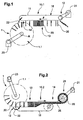
- FIGS 1 to 3 are very schematic representations of portions of various exemplary embodiments of the inventive device for processing piece goods (large numbers of products 20 or treated as units product groups consisting of a small number of individual products). All devices shown have, as an exemplary processing device 1, a processing drum 1.1 to which, according to FIG. 1, a supply unit 10. 1 and, according to FIG. 2, a removal unit 10. 2 are coupled.
- FIG. 3 shows a transfer unit 10.3 coupled on both sides to a respective processing drum 1.1 (combination of removal unit and supply unit).
- the supply, removal or transfer units 10.1, 10.2 or 10.3 each have a self-contained rail track 11, along the one Can be moved in succession plurality of product grippers, not shown.
- the product grippers are independent of each other or they are so together connected that the distances between successive product grippers are variable.
- the rail track connects a receiving area 12, in take the products gripper products 20, over a buffer area 13, in the Product grippers are buffered with products 20, with a delivery area 14, in give products 20 to the product gripper. From the delivery area 14 to the receiving area 12 runs a return path 16 for the return transport of product grippers without products, on which return line 16 the product gripper also buffered can be. If necessary, not all products will be in the delivery area delivered, so that also on the return line isolated product gripper Keep products.
- the drivable areas are in the receiving area 12
- Means arranged to isolate or take over in the case shown
- the Engage product gripper activate and move away. At least a part These functions are driven by a motor drive 21.
- the products 20 are released from the product grippers and positioned in the processing apparatus 1.
- These are the product gripper fed from the buffer area 13 of the positioning, clocked, for positioning deactivated and promoted, with the Eintaktung and deactivation to be exactly synchronized with the operation of the processing device 1.
- a coupling symbolized by the bold arrow 22
- the processing device 1 or at the periphery, for example, a provided mechanical output.
- the Weg Entrystician 10.2 shown in Figure 2 has substantially the same Functional units on how the feed unit 10.1 of Figure 1. These are also denoted by the same reference numerals.
- a means (bold arrow 22) coupled to the processing device 1 arranged for intermittent removal, in the delivery area a means of landfilling of the products 20, for example in flake formation on the feed belt 25 a Aufwickelstation 26.
- the product grab from taken from the buffer area 13, clocked in, deactivated and carried away.
- FIG. 3 shows a transfer unit arranged between two processing drums 1.1 10.3, which is essentially a receiving area 12 with a Temporary withdrawal means and delivery means 14 having means for clocking positioning, which two means for synchronization or are coupled to the drums 1.1 for synchronization and drive (bold Arrows 22).
- the movable feed units, Weg Equipmentsstrahlen and / or transfer units give this not only, as already described above, a great flexibility and simplicity for conversions but they prove themselves by the mechanical separation, which is very close to the processing runs, also as very simple and in particular easily accessible for maintenance, Adjustment work and troubleshooting.
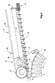
- FIGS. 4 and 5 show in more detail a movable feed unit 10.1 coupled to a processing drum 1.1 (eg saddle stitch drum with saddle-shaped supports).
- FIG. 4 shows the entire delivery unit 10.1, FIG. 5, its delivery area 14 on a larger scale.
- Functional units which have already been described in connection with FIGS. 1 to 3 are designated by the same reference numerals.
- the feed unit 10.1 is in any desired manner, for example manually with supplied stacked products.
- the feeding unit is on wheels or rollers 30 movable and supports height adjustable on the machine frame 31 of the collecting drum 1.1.
- In the delivery area 14 is a to the saddle-shaped pads 32nd the collecting drum 1.1 deliverable toothed belt 33 is provided, the teeth 34th are matched to the outer edges of the saddle-shaped pads 32 and the this is deliverable.
- the timing belt 33 is in the direction of the axis of the drum 1.1 relative to the rail track 11 and the product grippers 40 adjustable shifted.
- this displacement is dimensioned such that the Timing belt 33 in addition to its function as an output and a function as an axial stop for the exact alignment of the saddle-shaped pads 32 positioned Can take over products.
- a suitable transmission 36 provides a means for conveying of product grippers 40 from the buffer area 13 against the positioning and driven to latch the product grippers for positioning.
- This A means for promotion and Eintaktung is for example a corresponding subsidy screw 41 with an increasing towards the point of effective positioning Pitch.
- a Wegnsch Wegfördem the gripper 40 after positioning, for example a driving wheel 42, driven. All other necessary and to be driven for the positioning Means are driven by the toothed belt 33, for example an opening device 50, as shown schematically in Figure 4.
- the opening device 50 is used to open the products to be positioned so that they on the Saddle-shaped pads 32 of the drum 1.1 can be placed.
- the buffer area 13 is advantageously at a location of the rail track 11 provided, at which it falls in the direction against the Zuhege Scheme 14, so that the product grippers 40 are driven by gravity in this area and no mechanical drive must be provided.
- the product grippers are connected by means of slip clutch, are also buffer areas on rising or flat rail areas possible.
- a stacking shaft 51 is provided in the stacked Products are supplied and from these products in a conventional manner and singulated and detected by the product grippers 40.
- a motor Drive 21 drives all for the separation of the partial products from the stacking shaft 51, for their promotion to the point where they are covered by the product grabbers for the hooking of the grapples to this place and for the excavation of the Gripper from this point to the buffer area 13 necessary to be driven Medium on.
- the feed unit 10.1 which is shown in FIGS. 4 and 5, can be used for the Drive in the receiving area 12, so as a drive of the product gripper 40 to the feed and clocking in for the product intake and for the further promotion of the product grippers 40 at least in this area of the rail line 11 a continuously have moving conveyor member to which the product gripper 40, for example are magnetically coupled.
- Such a drive can also extend into the buffer area 13 extend, so that the buffer area also at a in the conveying direction rising piece of rail track 11 may be arranged.
- a system with a self-contained rail track with it independent movable product grippers and one continuously circulating Conveyor to which the product grippers are selectively coupled for example in Publication WO-99/33731 (F475).
- This system is in a feeding unit, as shown in Figures 4 and 5, as a recording drive used.
- FIG. 6 shows a further, exemplary embodiment of the device according to the invention for processing piece goods. Shown is a feed unit 10.1, which is coupled to a processing device 1 in the form of a circulation system 1.2 with V-shaped compartments 60. The products to be supplied 20 are introduced into the V-shaped compartments, for example for the production of multi-part products.
- the feed unit 10.1 is in turn supplied for the supply of stacked Products 20 designed and designated for the separation of products from the Stacking shaft 51 on a occupied with suction cups rotating separating wheel 61
- the product gripper 40 are both in the recording area 12 as well as in the delivery area 14 circumferential drive chains 62 provided in the buffer area 13 and on the return line 16 are the product gripper 40 powered by gravity.
- the Product gripper 40 in the receiving area 12 and discharge area 14 are, for example stationary scenes (not shown) provided.
- the coupling of the delivery drive for the means for positioning the products in the delivery area 14 of the supply unit 10.1 is also in this case by a Timing belt 33 realized, with the outer edges of the V-shaped compartments 60th of the circulating system 1.2 can be brought into engagement.
Abstract
Description
Die Erfindung liegt auf dem Gebiete der Stückgutbearbeitung und Stückgutförderung und betrifft eine Einrichtung nach dem Oberbegriff des ersten, unabhängigen Patentanspruchs. Die Einrichtung dient zur im wesentlichen seriellen Bearbeitung einer grossen Zahl von gleichen oder ähnlichen Produkten (Stückgut) und weist mindestens eine Bearbeitungsstation zur im wesentlichen seriellen Bearbeitung von Produkten auf, welcher mindestens einen Bearbeitungsstation über mindestens eine Zuführung zu bearbeitende Produkte zugeführt und von welcher Bearbeitungsstation über mindestens eine Wegführung bearbeitete Produkte weggeführt werden. Dabei kann eine Zuführung zu einer ersten Bearbeitungsstation mit einer Wegführung von einer zweiten Bearbeitungsstation zu einer Überführung kombiniert sein.The invention is in the field of general cargo processing and general cargo and relates to a device according to the preamble of the first independent claim. The device is used for essentially serial processing of a large number of identical or similar products (general cargo) and rejects at least a processing station for substantially serial processing of products on, which at least one processing station via at least one feeder supplied to processing products and from which processing station be processed away at least one way guide processed products. there may be a supply to a first processing station with a routing of a second processing station to be combined to a transfer.
Für das Zuführen, Wegführen bzw. Überführen sind Produkte hintereinander in die Bearbeitungsstation, von der Bearbeitungsstation weg bzw. von einer Bearbeitungsstation zu einer nächsten Bearbeitungsstation zu fördern. Für eine Zuführung werden Produkte vor dieser Förderung aus einer Lagerformation vereinzelt oder von einem vorgeschalteten Fördermittel übernommen und nach der Förderung einzeln taktweise für die Bearbeitung positioniert. Dazu kommt zur Entkoppelung von Vereinzelung oder Übernahme und Positionierung vorteilhafterweise eine Pufferung vor der Positionierung. Für eine Wegführung werden Produkte taktweise aus der Bearbeitung entnommen, gefördert und dann geordnet deponiert oder an ein nachgeschaltetes Fördermittel übergeben. Dabei kann vor dem Deponieren oder Übergeben ebenfalls eine Pufferung vorgesehen werden. Für eine Überführung werden Produkte einzeln oder in kleinen Gruppen und taktweise aus einer ersten Bearbeitung entnommen, gefördert und dann einzeln oder in kleinen Gruppen und taktweise für eine zweite Bearbeitung positioniert, wobei auch hier zwischen Entnehmen und Positionieren vorteilhafterweise eine Pufferung vorgesehen ist.For feeding, removing or transferring products are in succession in the Processing station, away from the processing station or from a processing station to promote to a next processing station. Become for a feeder Products before this promotion isolated from a storage formation or from a taken over upstream conveyor and after the promotion individually intermittently positioned for editing. Added to this is the decoupling of separation or takeover and positioning advantageously buffering before positioning. For a routing, products are gradually removed from the processing taken, promoted and then deposited in an orderly manner or to a downstream Hand over funds. It may also be before depositing or passing a buffering be provided. For a transfer, products are sold individually or taken in small groups and intermittently from a first processing, promoted and then individually or in small groups and intermittently for a second Positioning, whereby also between removal and positioning advantageously a buffering is provided.
In einer Zuführung muss das Mittel zum taktweisen Positionieren genau synchron mit der Bearbeitung betrieben werden. Dasselbe gilt für das Mittel zum taktweisen Entnehmen in einer Wegführung. Aus diesem Grunde sind mindestens diese Mittel üblicherweise starr mit den Mitteln zur Bearbeitung verbunden und werden meist auch über den gleichen Antrieb angetrieben.In a feeder, the means for intermittent positioning must be exactly synchronous be operated with the processing. The same applies to the means for intermittent Remove in a route guidance. For this reason, at least these means Usually rigidly connected with the means for processing and are usually also powered by the same drive.
Ein Beispiel für eine Einrichtung der oben genannten Stückgutbearbeitung ist eine Einrichtung zur Herstellung von Produkten aus einer Mehrzahl von Teilprodukten, beispielsweise die Herstellung von Druckprodukten, wie Zeitungen, Zeitschriften oder Broschüren, dadurch, dass für jedes Produkt mehrere, in verschiedenen Druckvorgängen hergestellte, sich mindestens inhaltlich voneinander unterscheidende Teilprodukte zusammengefügt und dann gegebenenfalls beispielsweise durch Heften oder Binden miteinander verbunden werden. Für die Bearbeitung, die in diesem Falle im wesentlichen aus einem Zusammenfügen verschiedener Teilprodukte besteht, werden entstehende Produkte von Zuführungsstelle zu Zuführungsstelle gefördert, wobei an jeder Zuführungsstelle ein Teilprodukt zu dem entstehenden Produkt zugefügt wird und wobei jede Zuführungsstelle üblicherweise mit einem Teilproduktetyp beliefert wird. Die zusammengefügten Teilprodukte werden dann beispielsweise durch Heften oder Binden zu einem Produkt verbunden, das aus der Bearbeitung weggeführt wird.An example of a device of the aforementioned general cargo processing is a Device for producing products from a plurality of partial products, For example, the production of printed products, such as newspapers, magazines or brochures, in that for each product several, in different printing processes manufactured, at least contentwise different from each other Sub-products assembled and then optionally, for example, by stapling or bindings. For editing, in this case essentially consists of a combination of different partial products, resulting products are promoted from feed point to feed point, wherein at each feed point a partial product is added to the resulting product and wherein each delivery site is usually of a partial product type is supplied. The assembled partial products then become, for example connected by stapling or binding to a product that is out of work is led away.
Für die genannte Herstellung von Druckprodukten besteht die Bearbeitung im wesentlichen aus einer Mehrzahl von aufeinanderfolgenden Schritten, in denen je ein gefaltetes Teilprodukt auf eine sattelförmige Auflage bzw. auf ein auf der sattelförmigen Auflage bereits aufliegendes, gefaltetes Teilprodukt, je ein gefaltetes Teilprodukt in ein V-förmiges Abteil bzw. in einem in dem V-förmigen Abteil bereits eingesteckten, gefalteten Teilprodukt oder je ein gefaltetes oder ungefaltetes Teilprodukt auf einer Stapelauflage bzw. auf einem bereits auf der Stapelauflage gestapelten, gefalteten oder ungefalteten Teilprodukt positioniert wird.For the mentioned production of printed products, the processing consists essentially from a plurality of consecutive steps, one each folded partial product on a saddle-shaped pad or on a saddle-shaped Edition already resting, folded partial product, one folded partial product in a V-shaped compartment or in an already inserted in the V-shaped compartment, folded partial product or one folded or unfolded partial product on a stack support or on an already stacked on the stack support, folded or unfolded partial product is positioned.
Einrichtungen für die genannte Herstellung von Druckprodukten aus je einer Mehrzahl von Teilprodukten weisen für die Förderung der entstehenden Produkte beispielsweise eine rotierende Trommel auf mit einer Vielzahl von sattelförmigen Auflagen oder V-förmigen Abteilen, die regelmässig um den Trommelumfang verteilt sind und sich in axialer Richtung erstrecken und auf oder in denen positioniert die entstehenden Druckprodukte während der Trommelrotation in axialer Richtung von Zuführungsstelle zu Zuführungsstelle verschoben werden. Anstelle der genannten Trommeln können auch Umlaufsysteme zur Anwendung kommen, in denen sattelförmige Auflagen, V-förmige Abteile oder Stapelauflagen auf einer endlosen Bahn gefördert werden, wobei die Produkte während ihrer Entstehung auf den sattelförmigen Auflagen oder ebenen Stapelauflagen oder in den V-förmigen Abteilen über ein im wesentlichen geradliniges Bahnstück gefördert werden und die Zuführungsströme der Teilprodukte an den Zuführungsstellen von oben in dieses im wesentlichen geradlinige Bahnstück münden. Der im wesentlichen geradlinigen Förderung der entstehenden Produkte kann gegebenenfalls in ähnlicher Weise, wie dies in den genannten Trommeln der Fall ist, eine Verschiebung quer zur allgemeinen Förderrichtung überlagert sein. Ebenso ist es möglich, die entstehenden Produkte mit im wesentlichen stationären Mitteln auf einer entsprechenden Unterlage von Zuführungsstelle zu Zuführungsstelle zu verschieben (sog. lineare Systeme).Means for said production of printed products of a plurality of partial products point to the promotion of the resulting products, for example a rotating drum with a variety of saddle-shaped pads or V-shaped compartments regularly distributed around the circumference of the drum are and extend in the axial direction and positioned on or in which resulting printed products during the drum rotation in the axial direction of Zuführungstelle be moved to Zuführungstelle. Instead of the mentioned Drums can also be used circulation systems in which saddle-shaped Pads, V-shaped compartments or pile supports on an endless track be promoted, whereby the products during their emergence on the saddle-shaped Pads or flat pile supports or in the V-shaped compartments above a conveyed in a substantially rectilinear track piece and the feed streams the sub-products at the feed points from above into this substantially rectilinear Mouthpiece. The essentially straightforward promotion of the resulting Products may optionally be similar to those mentioned in the above Drumming is the case, a shift transversely to the general conveying direction be superimposed. It is also possible to use the resulting products with essentially stationary means on a corresponding base of feeder site to move to Zuführungsstelle (so-called linear systems).
Einrichtungen zur Herstellung von Produkten aus einer Mehrzahl von Teilprodukten, beispielsweise zur Herstellung von Druckprodukten aus einer Mehrzahl von bedruckten Teilprodukten, benötigen eine Mehrzahl von Zuführungsstellen, deren notwendige Anzahl je nach herzustellendem Produkt variieren kann, deren Ausgestaltung je nach Zulieferungsart und Format der zuzuführenden Teilprodukte variieren kann und deren Abstände voneinander entlang der Förderstrecke der entstehenden Produkte je nach Format der Teilprodukte oder der entstehenden Produkte und/oder je nach zwischen den Zuführungsstellen vorzunehmenden, weiteren Bearbeitungsschritten variieren kann. Die für die Herstellung eines einzigen Produktetyps notwendigen Zuführungsmittel können gleich oder voneinander verschieden sein. Bei einem Wechsel von der Herstellung eines Produktetyps zur Herstellung eines anderen Produktetyps müssen die Zuführungsmittel gegebenenfalls umgebaut, abgebaut und ersetzt, neu eingestellt und/oder aktiviert bzw. desaktiviert werden, was mit einem grossen Arbeits- und Zeitaufwand verbunden ist.Devices for the production of products from a plurality of sub-products, For example, for the production of printed products from a plurality of printed Partial products, require a plurality of feeding points, the necessary Number may vary depending on the product to be produced, their design vary depending on the type of delivery and format of the partial products to be supplied can and their distances from each other along the conveying path of the resulting Products depending on the format of the partial products or the resulting products and / or depending on between the feed points to be made, further processing steps can vary. The necessary for the production of a single product type Delivery means may be the same or different. at a change from the production of one product type to the production of another If necessary, the feed means must be dismantled and dismantled and replaced, reset and / or activated or deactivated, what with a great effort and time is connected.
In bekannten Einrichtungen zur Herstellung von Druckprodukten aus einer Mehrzahl von bedruckten Teilprodukten sind an vorgegebenen Zuführungsstellen Zuführungsmittel bzw. je mindestens ein Teilproduktepuffer und ein Mittel zum taktweisen Positionieren von Teilprodukten fest mit dem Mittel zur Förderung der entstehenden Produkte verbunden. Die einfachsten dieser Einrichtungen weisen sogenannte Anleger als Zuführungsmittel auf, in welchen Anlegern die zuzuführenden Teilprodukte lose gestapelt gepuffert und aus dem Stapel für das Positionieren vereinzelt werden und welche Anleger manuell mit Teilprodukten beliefert werden. Weiterentwicklungen (z.B. gemäss Publikation EP-0550828 bzw. US-5324014) weisen zusätzlich mehr oder weniger automatisierte Zulieferungsmittel in Form von beispielsweise Abwickelstationen auf, wobei auch diese Zulieferungsmittel fest mit einer bestimmten Zuführungsstelle und damit fest mit dem Mittel zur Förderung der entstehenden Produkte verbunden sind.In known devices for the production of printed products from a plurality of printed partial products are supply means at predetermined feed points or at least one partial product buffer and one means for intermittent Positioning of partial products fixed with the means of promoting the resulting Products connected. The simplest of these devices have so-called investors as feed means in which investors the supplied partial products buffered loose and separated from the stack for positioning and which investors are supplied manually with partial products. developments (for example, according to publication EP-0550828 or US-5324014) additionally more or less automated supply means in the form of for example Unwinding on, with these supply means firmly with a certain Feeding point and thus firmly with the means for the promotion of the arising Products are connected.
Alle derartigen Einrichtungen eignen sich wenig für einen flexiblen Betrieb zur Herstellung von relativ kleinen Auflagen von Produkten, die sich nicht nur inhaltlich und in der Zahl der Teilprodukte unterscheiden sondern auch im Format der Teilprodukte und in der für die Teilprodukte notwendigen Handhabung.All such devices are not well suited for flexible manufacturing operation from relatively small editions of products that are not just content and in the number of partial products but also in the format of the partial products and in the handling necessary for the partial products.
Ein Ansatz zur Flexibilisierung ist in der Publikation US-5088711 (Newsome) zu finden, in welcher Publikation eine fahrbare Vorrichtung beschrieben wird, die wahlweise an einen der fest montierten Anleger verschiedener Zuführungsstellen angeschlossen werden kann. Die Vorrichtung wird manuell mit Teilprodukten beliefert, wobei offenbar die Belieferung in grösseren Batches möglich ist als die direkte Belieferung des Anlegers. Die Teilprodukte werden dann von der Vorrichtung auf dem Anleger lose gestapelt. Die mit dieser Einrichtung zu erreichende Flexibilität ist auf der Seite der Teilprodukt-Pufferung und der Teilprodukte-Positionierung durch die Flexibilität fest montierter Anleger und auf der Seite der Teilproduktzulieferung durch die Flexibilität des Bedienungspersonals gegeben, das heisst, mindestens in Bezug auf Teilprodukteformate und Teilproduktehandhabung ist sie nicht grösser als für Einrichtungen mit direkt manuell belieferten Anlegern. Die mit der beschriebenen Einrichtung erreichbare Flexibilität bezieht sich im wesentlichen nur darauf, dass die Vorrichtung von einer momentan nicht aktiven Zuführungsstelle an eine aktive Zuführungsstelle verschoben werden kann.One approach to flexibilization is in the publication US-5088711 (Newsome) find in which publication a mobile device is described which optionally to one of the permanently installed feeders of different feeding points can be connected. The device is manually supplied with partial products, apparently delivery in larger batches is possible than the direct Supply to the investor. The partial products are then absorbed by the device piled loose on the feeder. The flexibility to be achieved with this device is on the page of partial product buffering and partial product positioning the flexibility of permanently installed feeders and on the side of the sub-product supply given by the flexibility of the operator, that is, at least in Regarding partial product formats and partial product handling, it is no bigger than for facilities with directly manually supplied investors. The with the described Facility achievable flexibility refers essentially only to the fact that the Device from a currently non-active delivery site to an active delivery site can be moved.
Ein weiterer Ansatz zur Flexibilisierung der Herstellung von Druckprodukten aus je einer Mehrzahl von Teilprodukten, insbesondere der Flexibilisierung der Zulieferungsseite, ist in der Publikation DE-19634568 (bzw. US-5799897) beschrieben. Mit der in dieser Publikation beschriebenen Einrichtung wird versucht, das Problem der Flexibilität durch Standardisierung zu lösen. Es werden in einem der eigentlichen Zuführung vorgelagerten Schritt aus verschiedensten Lagerformationen von verschiedenen Teilproduktetypen standardisierte Zuführungsformationen erstellt, die im wesentlichen ohne Veränderung der Zuführungsformation in Zuführungsstellen fest zugeordnete Zuführungspuffer gespeist werden. Aus den Zuführungspuffern werden die Teilprodukte wiederum im wesentlichen ohne Veränderung der Formation entnommen und zu entstehenden Produkten zugefügt. Auch hier bleibt die Flexibilität auf die Flexibilität der an den Zuführungsstellen fest montierten Zuführungspuffern und Mitteln zum Positionieren beschränkt.Another approach to flexibilizing the production of printed products from each a number of sub-products, in particular the flexibility of the supply side, is described in the publication DE-19634568 (or US-5799897). The device described in this publication attempts to solve the problem flexibility through standardization. It will be in one of the actual Feeder upstream step from various storage formations created standardized feed information from different sub-product types, essentially without changing the feed formation at feed points dedicated feed buffers are fed. From the feeder buffers In turn, the sub-products are essentially without altering the formation removed and added to resulting products. Again, the flexibility remains on the flexibility of the feed buffers fixedly mounted at the feed points and means for positioning.
Die oben genannten Bedürfnisse nach Flexibilisierung manifestieren sich insbesondere an den Zuführungen zu den genannten Einrichtungen zur Herstellung von Produkten aus einer Mehrzahl von Teilprodukten, welche Zuführungen natürlich auch als Überführungen ausgestaltet sein können. Sie sind aber ebenso vorhanden für die in einer derartigen Einrichtung vorzusehende Wegführung, die ebenfalls als Überführung ausgestaltet sein kann, und ebenso für Zuführungen, Wegführungen und Überführungen in Einrichtungen, mit einer oder mehreren Bearbeitungsstationen, die nur je eine Zuführung benötigen.The above-mentioned needs for flexibility manifest themselves in particular at the feeders to the said facilities for the manufacture of products from a plurality of partial products, which feeds, of course, too can be configured as overpasses. But they are also available for the in such a device to be provided Wegführung, also as a transfer can be designed, and also for additions, routes and overpasses in facilities, with one or more workstations that only ever need a feeder.
Die Erfindung stellt sich nun die Aufgabe, einen weiteren, grossen Schritt in Richtung erhöhter Flexibilität für Einrichtungen zur Bearbeitung von Stückgut zu realisieren und zwar ohne wesentlichen vorrichtungsmässigen Mehraufwand. Die Aufgabe der Erfindung besteht also darin, eine Einrichtung zur Bearbeitung von Stückgut, die mindestens eine Bearbeitungsstation mit mindestens einer Zuführung und mindestens einer Wegführung aufweist, wobei Zuführungen mit Wegführungen gegebenenfalls zu Überführungen kombiniert sind, zu schaffen, welche Einrichtung insbesondere sehr einfach umrüstbar ist für aufeinanderfolgende Betriebsphasen zur Bearbeitung von sich voneinander wesentlich unterscheidenden Produkten.The invention now has the task of making another, big step in the direction to realize increased flexibility for facilities for processing general cargo and without significant device overhead extra effort. The task The invention thus consists in a device for processing piece goods, the at least one processing station with at least one feeder and at least a Wegführung, with leads with guides if necessary to create overpasses, to create which device in particular It is very easy to convert for successive phases of operation of products differing substantially from each other.
Für eine Stückgutbearbeitung, die darin besteht, je eine Mehrzahl von Teilprodukten zu einem Produkt zusammenzufügen, soll es also beispielsweise mit der Erfindung ohne weiteres möglich werden, dass die in aufeinanderfolgenden Betriebsphasen herzustellenden Produktetypen sich voneinander unterscheiden bezüglich Anzahl der Teilprodukte, bezüglich Teilprodukteformaten, bezüglich für die Teilprodukte notwendigen Handhabungsarten und/oder bezüglich zwischen Zuführungsstellen durchzuführenden, weiteren Bearbeitungsschritten. Es soll also mit der erfindungsgemässen Einrichtung möglich sein, ohne grossen Umbauaufwand die Art des an einer Zuführungsstelle zuzuführenden Teilproduktes in weiteren Grenzen, als bis anhin möglich, zu wechseln und/oder Bereiche der Förderstrecke der entstehenden Produkte für andere Bearbeitungen als Teilproduktezuführungen frei zu machen und/oder bei reduziertem Betrieb (Herstellung von Produkten aus einer relativ kleinen Zahl von Teilprodukten) ungebrauchte Ausrüstung gegebenenfalls in parallel laufenden Herstellungen anderer Produkte einzusetzen.For a piece goods processing, which consists of a plurality of sub-products to put it together to a product, so it should, for example, with the invention be readily possible that in successive phases of operation product types to be different from each other in number of the sub-products, in terms of sub-product formats, re for the sub-products necessary handling types and / or with respect to between feeding points to be performed, further processing steps. It should therefore with the inventive Facility to be possible, without much modification the nature of the a supply point to be supplied partial product in other limits, as to Therefore possible to change and / or areas of the conveyor line of the resulting Make products available for processing other than partial product supply and / or with reduced operation (producing products from a relatively small size) Number of partial products) unused equipment possibly in parallel ongoing preparations of other products.
Die gestellte Aufgabe wird gelöst durch die Einrichtung zur Bearbeitung von Stückgut, wie sie in den Patentansprüchen definiert ist.The stated object is achieved by the device for processing piece goods, as defined in the claims.
Die Erfindung basiert auf der Idee, zwischen Bearbeitung und Zuführung oder Wegführung eine mechanische Trennung derart vorzunehmen, dass auf der Bearbeitungsseite der Trennung Zuförderungs- bzw. Wegförderungsfunktionen entfallen. Die mechanische Trennung verläuft also für die Zuführung zwischen der Bearbeitung und dem Positionieren der Produkte für die Bearbeitung, bei der Wegführung zwischen der Bearbeitung und der Entnahme der Produkte aus der Bearbeitung, wobei die Bearbeitung nur mit dem notwendigen Minimum an Förderung kombiniert ist. Die durch die genannte Trennung von der Bearbeitung mechanisch getrennten Zuführungs-, Wegführungs- oder Überführungsfunktionen werden durch mechanische Einheiten für Zuführung, Wegführung oder Überführung realisiert, welche Einheiten verfahrbar und vorteilhafterweise einstellbar sind und welche Einheiten an eine Koppelstelle einer Bearbeitungsvorrichtung derart ankoppelbar sind, dass mindestens ein zu einer derartigen Einheit gehörendes Mittel zur Produktepositionierung oder zur Produkteentnahme durch diese Koppelung mit der Bearbeitungsvorrichtung synchronisiert und vorteilhafterweise durch diese Koppelung von der Bearbeitungsvorrichtung nicht nur synchronisiert sondern auch angetrieben wird. The invention is based on the idea between machining and feeding or routing to perform a mechanical separation such that on the machining side the separation of supply and removal functions is eliminated. The mechanical Separation thus runs for the supply between the processing and Positioning of the products for machining, when routing between the processing and the removal of the products from the processing, whereby the processing only combined with the necessary minimum of promotion. The by the separation from machining mechanically separated feed, Wegführungs- or transfer functions are by mechanical Units for supply, routing or transfer realized which units movable and advantageously adjustable and which units to a coupling point a processing device can be coupled such that at least one Product positioning means belonging to such a unit or Product removal synchronized by this coupling with the processing device and advantageously by this coupling of the processing device not only synchronized but also driven.
Die erfindungsgemässe Einrichtung für die Stückgutbearbeitung weist also mindestens eine Bearbeitungsvorrichtung auf mit mindestens je einer Zuführung und mindestes je einer Wegführung, wobei mindestens eine Zu- oder Wegführung als verfahrbare Zuführungs- bzw. Wegführungseinheit ausgestaltet ist. Eine derartige Einheit weist ein antreibbares Mittel zum taktweisen Positionieren von je einem Produkt in der Bearbeitungsvorrichtung oder ein antreibbares Mittel zur taktweisen Entnahme von je einem Produkt aus der Bearbeitungsvorrichtung auf, welches antreibbare Mittel mit der Bearbeitungsvorrichtung koppelbar ist für die Synchronisierung dieses antreibbaren Mittels durch die Bearbeitungsvorrichtung oder für den Antrieb dieses antreibbaren Mittels kombiniert mit der Synchronisierung durch die Bearbeitungsvorrichtung.The device according to the invention for handling piece goods therefore has at least a processing device with at least one feeder and at least depending on a routing, with at least one access or routing as movable Supply or removal unit is designed. Such a unit has a drivable means for the cyclic positioning of each product in the processing device or a drivable means for cyclic removal each of a product from the processing device, which drivable Means with the processing device can be coupled for the synchronization of this driven means by the processing device or for driving this drivable means combined with the synchronization by the processing device.
Die Einheiten weisen zusätzlich zum oben genannten antreibbaren Mittel zum Positionieren oder Entnehmen ein weiteres antreibbares Mittel auf. Dieses zweite antreibbare Mittel ist für eine Zuführung ein Mittel zum Vereinzeln oder Übernehmen, für eine Wegführung ein Mittel zum Deponieren oder Übergeben und für eine Überführung ein Mittel zum Positionieren oder ein Mittel zum Entnehmen. Die Antriebe der beiden antreibbaren Mittel sind voneinander unabhängig und vorteilhafterweise ist zwischen den beiden Mitteln ein Pufferbereich angeordnet.The units have in addition to the above-mentioned drivable means for positioning or take out another drivable means. This second drivable Means is for a feeder a means of separating or taking over, for a route a means for depositing or handing over and for a transfer a means for positioning or a means for removal. The drives the two drivable means are independent and advantageous a buffer area is arranged between the two means.
Die Einheiten weisen ein in sich geschlossenes Schienensystem auf, auf dem eine Mehrzahl von Produktegreifern mit variierenden Abständen voneinander verfahrbar sind, wobei die Produktegreifer für eine Aktivierung bzw. Desaktivierung ansteuerbar sind.The units have a self-contained rail system on which a Plurality of product grippers with varying distances from each other are, with the product gripper controllable for activation or deactivation are.
Die Koppelbarkeit der antreibbaren Mittel zum Positionieren bzw. Entnehmen an die Bearbeitungsvorrichtung kann beispielsweise durch sensorische Mittel realisiert werden, welche sensorischen Mittel die Bearbeitungsfunktion der Bearbeitungsvorrichtung aufnimmt und Steuersignale für die Steuerung eines Antriebs eines Mittels zum Positionieren oder Entnehmen erzeugt. Vorteilhafterweise ist das Mittel zur Koppelung ein an der Peripherie der Bearbeitungsvorrichtung ankoppelbarer Abtrieb, der von der Bearbeitungsvorrichtung nicht nur die Synchronisation sondern auch die Antriebsleistung abnimmt. Ein derartiger Abtrieb besteht beispielsweise aus einem Zahnriemen, der mit sich im Bearbeitungstakt bewegenden Elementen an der Peripherie der Bearbeitungsvorrichtung in Eingriff bringbar ist.The coupling of the drivable means for positioning or removal of the Processing device can be realized for example by sensory means, which sensory means the processing function of the processing device receives and control signals for the control of a drive of a means for Positioning or removal generated. Advantageously, the means for coupling an output coupled to the periphery of the processing device, the from the processing device not only the synchronization but also the Drive power decreases. Such a downforce consists for example of a Timing belt, which moves with the machining cycle moving elements on the periphery the processing device is engageable.
Die erfindungsgemässe Einrichtung wird im folgenden anhand von beispielhaften Ausführungsformen im Detail beschrieben. Dabei zeigen:
-
Figuren 1 bis 3 - drei beispielhafte, einfache Ausführungsformen der erfindungsgemässen Einrichtung mit rotierenden Trommeln als Bearbeitungsvorrichtungen und mit einer Zuführungseinheit (Figur 1), Wegführungseinheit (Figur 2) oder einer Überführungseinheit (Figur 3);
- Figur 4
- eine beispielhafte Zuführungseinheit für die Zuführung von in Stapeln angelieferten Produkten zu einer Berarbeitungstrommel mit sattelförmigen Auflagen;
- Figur 5
- das an die Bearbeitungstrommel gekoppelte Mittel zur Positionierung der Zuführungseinheit gemäss Figur 4 in einem grösseren Massstab;
- Figur 6
- eine Zuführungseinheit für die Zuführung von in Stapeln angelieferten Produkten zu einem Umlaufsystem mit V-förmigen Abteilen.
- FIGS. 1 to 3
- three exemplary, simple embodiments of the inventive device with rotating drums as processing devices and with a feed unit (Figure 1), Wegführungseinheit (Figure 2) or a transfer unit (Figure 3);
- FIG. 4
- an exemplary feed unit for the delivery of products delivered in stacks to a dressing drum with saddle-shaped pads;
- FIG. 5
- the coupled to the processing drum means for positioning the supply unit according to Figure 4 on a larger scale;
- FIG. 6
- a feed unit for feeding products delivered in stacks to a circulating system with V-shaped compartments.
Figuren 1 bis 3 sind sehr schematische Darstellungen von Teilbereichen verschiedener,
beispielhafter Ausführungsformen der erfindungsgemässen Einrichtung zur Bearbeitung
von Stückgut (grosse Zahlen von Produkten 20 oder von als Einheiten behandelten
Produktegruppen bestehend aus einer kleinen Zahl von einzelnen Produkten).
Alle dargestellten Einrichtungen weisen als beispielhafte Bearbeitungsvorrichtung
1 eine Bearbeitungstrommel 1.1 auf, an die gemäss Figur 1 eine Zuführungseinheit
10.1 und gemäss Figur 2 eine Wegführungseinheit 10.2 gekoppelt ist. Figur 3
zeigt eine beidseitig an je eine Bearbeitungstrommel 1.1 angekoppelte Überführungseinheit
10.3 (Kombination von Wegführungseinheit und Zuführungseinheit). Figures 1 to 3 are very schematic representations of portions of various exemplary embodiments of the inventive device for processing piece goods (large numbers of
Die Zuführungs-, Wegführungs- oder Überführungseinheiten 10.1, 10.2 oder 10.3
weisen je einen in sich geschlossenen Schienenstrang 11 auf, entlang dem eine
Mehrzahl von nicht dargestellten Produktegreifern hintereinander verfahrbar sind.
Die Produktegreifer sind dabei voneinander unabhängig oder sie sind derart miteinander
verbunden, dass die Abstände zwischen aufeinanderfolgenden Produktegreifern
variierbar sind. Der Schienenstrang verbindet einen Aufnahmebereich 12, in
dem Produktegreifer Produkte 20 aufnehmen, über einem Pufferbereich 13, in dem
Produktegreifer mit Produkten 20 gepuffert werden, mit einem Abgabebereich 14, in
dem Produktegreifer Produkte 20 abgeben. Vom Abgabebereich 14 zum Aufnahmebereich
12 verläuft eine Rücklaufstrecke 16 zum Rücktransport von Produktegreifern
ohne Produkte, auf welcher Rücklaufstrecke 16 die Produktegreifer ebenfalls gepuffert
werden können. Gegebenenfalls werden im Abgabebereich nicht ganz alle Produkte
abgegeben, so dass auch auf der Rücklaufstrecke vereinzelte Produktegreifer
Produkte halten.The supply, removal or transfer units 10.1, 10.2 or 10.3
each have a self-contained
Für die Zuführungseinheit gemäss Figur 1 sind im Aufnahmebereich 12 die antreibbaren
Mittel zum Vereinzeln oder Übernehmen angeordnet, im dargestellten Falle
beispielsweise ein Mittel zum Übernehmen der Produkte 20 aus einer kontinuierlich
angelieferten Schuppenformation von Produkten 20. Für die Übernahme sind die
Produktegreifer einzutakten, zu aktivieren und wegzufördern. Mindestens ein Teil
dieser Funktionen wird über einen motorischen Antrieb 21 angetrieben. For the feed unit according to FIG. 1, the drivable areas are in the receiving
Im Abgabebereich 14 werden die Produkte 20 von den Produktegreifern entlassen
und in der Bearbeitungsvorrichtung 1 positioniert. Dazu werden die Produktegreifer
aus dem Pufferbereich 13 der Positionierung zugefördert, eingetaktet, für die Positionierung
desaktiviert und weggefördert, wobei die Eintaktung und die Desaktivierung
genau mit dem Betrieb der Bearbeitungsvorrichtung 1 zu synchronisieren sind.
Zu diesem Zwecke und vorteilhafterweise auch zum Antrieb des Mittels zum Positionieren
ist in diesem Bereich eine Kopplung (symbolisiert durch den fetten Pfeil
22) an die Bearbeitungsvorrichtung 1, bzw. an deren Peripherie, beispielsweise ein
mechanischer Abtrieb vorgesehen.In the
Es ist in einer Zuführungseinheit einer erfindungsgemässen Einrichtung möglich und vorteilhaft, den Pufferbereich derart auszulegen, dass er sehr nahe an die Stelle reicht, an der die Produkte von den Produktegreifern entlassen und in der Bearbeitungsvorrichtung positioniert werden.It is possible in a feed unit of a device according to the invention and advantageous to design the buffer area such that it is very close to the location ranges at which the products are released from the product grippers and in the processing device be positioned.
Die in Figur 2 dargestellte Wegführungseinheit 10.2 weist im wesentlichen dieselben
Funktionseinheiten auf wie die Zuführungseinheit 10.1 der Figur 1. Diese sind auch
mit denselben Bezugsziffern bezeichnet. Im Aufnahmebereich der Wegführungseinheit
ist ein an die Bearbeitungsvorrichtung 1 angekoppeltes (fetter Pfeil 22) Mittel
zum taktweisen Entnehmen angeordnet, im Abgabebereich ein Mittel zum Deponieren
der Produkte 20, beispielsweise in Schuppenformation auf dem Zuführungsband
25 einer Aufwickelstation 26. Für das Deponieren werden die Produktegreifer aus
dem Pufferbereich 13 entnommen, eingetaktet, desaktiviert und weggefördert. Dazu
weist die Einheit im Abgabebereich einen motorischen Antrieb auf oder ist an den
Antrieb 21 der Aufwickelstation gekoppelt.The Wegführungseinheit 10.2 shown in Figure 2 has substantially the same
Functional units on how the feed unit 10.1 of Figure 1. These are also
denoted by the same reference numerals. In the receiving area of the Wegführungseinheit
is a means (bold arrow 22) coupled to the
Figur 3 stellt eine zwischen zwei Bearbeitungstrommeln 1.1 angeordnete Überführungseinheit
10.3 dar, die im wesentlichen einen Aufnahmebereich 12 mit einem
Mittel zum taktweisen Entnehmen und einen Abgabebereich 14 mit einem Mittel
zum taktweisen Positionieren aufweist, welche beiden Mittel für Synchronisation
oder für Synchronisation und Antrieb an die Trommeln 1.1 angekoppelt sind (fette
Pfeile 22).FIG. 3 shows a transfer unit arranged between two processing drums 1.1
10.3, which is essentially a receiving
Die verfahrbaren Zuführungseinheiten, Wegführungseinheiten und/oder Überführungseinheiten der erfindungsgemässen Einrichtung geben dieser nicht nur, wie bereits oben beschrieben, eine grosse Flexibilität und Einfachheit für Umbauten sondern sie erweisen sich durch die mechanische Trennung, die sehr nahe bei der Bearbeitung verläuft, auch als sehr einfach und insbesondere einfach zugänglich für Unterhalt, Einstellungsarbeiten und Störungsbehebung.The movable feed units, Wegführungseinheiten and / or transfer units The inventive device give this not only, as already described above, a great flexibility and simplicity for conversions but they prove themselves by the mechanical separation, which is very close to the processing runs, also as very simple and in particular easily accessible for maintenance, Adjustment work and troubleshooting.
Selbstverständlich ist es möglich, dass in einer erfindungsgemässen Einrichtung eine Mehrzahl von Zuführungseinheiten gemäss Figur 1, Wegführungseinheiten gemäss Figur 2 und/oder Überführungseinheiten gemäss Figur 3 vorgesehen sind.Of course, it is possible that in a device according to the invention a A plurality of supply units according to FIG. 1, routing units according to FIG FIG. 2 and / or transfer units according to FIG. 3 are provided.
Figuren 4 und 5 zeigen mehr im Detail eine an eine Bearbeitungstrommel 1.1 (z.B.
Sammelhefttrommel mit sattelförmigen Auflagen) gekoppelte, verfahrbare Zuführungseinheit
10.1. Figur 4 zeigt die ganze Zuführungseinheit 10.1, Figur 5 deren Abgabebereich
14 in einem grösseren Massstab. Funktionseinheiten, die bereits im Zusammenhang
mit den Figuren 1 bis 3 beschrieben wurden, sind mit den gleichen Bezugsziffern
bezeichnet. FIGS. 4 and 5 show in more detail a movable feed unit 10.1 coupled to a processing drum 1.1 (eg saddle stitch drum with saddle-shaped supports). FIG. 4 shows the entire delivery unit 10.1, FIG. 5, its
Die Zuführungseinheit 10.1 wird in beliebiger Weise, beispielsweise manuell mit
gestapelten Produkten beliefert. Die Zuführungseinheit ist auf Rädern oder Rollen 30
verfahrbar und stützt sich höheneinstellbar auf dem Maschinengestell 31 der Sammeltrommel
1.1 ab. Im Abgabebereich 14 ist ein an die sattelförmigen Auflagen 32
der Sammeltrommel 1.1 zustellbarer Zahnriemen 33 vorgesehen, dessen Zähne 34
auf die Aussenkanten der sattelförmigen Auflagen 32 abgestimmt sind und der an
diese zustellbar ist. Der Zahnriemen 33 ist in der Richtung der Achse der Trommel
1.1 gegenüber dem Schienenstrang 11 bzw. den Produktegreifern 40 einstellbar verschoben.
Vorteilhafterweise ist diese Verschiebung derart dimensioniert dass der
Zahnriemen 33 neben seiner Funktion als Abtrieb auch eine Funktion als axialer Anschlag
für die genaue Ausrichtung der auf den sattelförmigen Auflagen 32 positionierten
Produkte übernehmen kann.The feed unit 10.1 is in any desired manner, for example manually with
supplied stacked products. The feeding unit is on wheels or
Durch den Zahnriemen 33 wird über ein geeignetes Getriebe 36 ein Mittel zum Fördern
von Produktegreifern 40 aus dem Pufferbereich 13 gegen die Positionierstelle
und zum Eintakten der Produktegreifer für die Positionierung angetrieben. Dieses
Mittel zur Förderung und Eintaktung ist beispielsweise eine entsprechende Förderschraube
41 mit einer gegen die Stelle der effektiven Positionierung zunehmenden
Steigung. Zudem wird durch den Zahnriemen 33 ein Wegfördermittel zum Wegfördem
der Greifer 40 nach dem Positionieren, beispielsweise ein Mitnehmerrad 42,
angetrieben. Alle weiteren für die Positionierung notwendigen und anzutreibenden
Mittel werden über den Zahnriemen 33 angetrieben, beispielsweise eine Öffnungsvorrichtung
50, wie sie in der Figur 4 schematisch dargestellt ist. Die Öffnungsvorrichtung
50 dient zum Öffnen der zu positionierenden Produkte, damit sie auf den
sattelförmigen Auflagen 32 der Trommel 1.1 aufgelegt werden können.By means of the
Der Pufferbereich 13 ist vorteilhafterweise an einer Stelle des Schienenstranges 11
vorgesehen, an der dieser in Richtung gegen den Zufügebereich 14 abfällt, so dass
die Produktegreifer 40 in diesem Bereich von der Schwerkraft angetrieben werden
und kein mechanischer Antrieb vorgesehen werden muss. Mit einem Antrieb mit
dem die Produktegreifer mittels Schlupfkupplung verbindbar sind, sind auch Pufferbereiche
auf ansteigenden oder ebenen Schienenbereichen möglich. The
Im Aufnahmebereich 12 (Figur 4) ist ein Stapelschacht 51 vorgesehen, in den gestapelte
Produkte geliefert werden und aus dem diese Produkte in an sich bekannter Art
und Weise vereinzelt und von den Produktegreifern 40 erfasst werden. Ein motorischer
Antrieb 21 treibt alle für die Vereinzelung der Teilprodukte aus dem Stapelschacht
51, für ihre Förderung zu der Stelle, wo sie von den Produktegreifern erfasst
werden, für die Eintaktung der Greifer zu dieser Stelle und für die Wegförderung der
Greifer von dieser Stelle bis zum Pufferbereich 13 notwendigen, anzutreibenden
Mittel an.In the receiving area 12 (Figure 4) a stacking
Die Zuführungseinheit 10.1, die in den Figuren 4 und 5 dargestellt ist, kann für den
Antrieb im Aufnahmebereich 12, also als Antrieb der Produktegreifer 40 zur Zuförderung
und Eintaktung zur Produkteaufnahme und zur Weiterförderung der Produktegreifer
40 mindestens in diesem Bereich des Schienenstranges 11 ein kontinuierlich
sich bewegendes Förderorgan aufweisen, an das die Produktegreifer 40 beispielsweise
magnetisch koppelbar sind. Ein derartiger Antrieb kann sich auch bis in den Pufferbereich
13 erstrecken, so dass der Pufferbereich auch an einem in Förderrichtung
steigenden Stück des Schienenstranges 11 angeordnet sein kann.The feed unit 10.1, which is shown in FIGS. 4 and 5, can be used for the
Drive in the receiving
Ein System mit einem in sich geschlossenen Schienenstrang mit darauf unabhängig voneinander verfahrbaren Produktegreifern und einem kontinuierlich umlaufenden Förderorgan, an das die Produktegreifer wahlweise ankoppelbar sind, ist beispielsweise in der Publikation WO-99/33731 (F475) beschrieben. Dieses System ist in einer Zuführungseinheit, wie sie in den Figuren 4 und 5 dargestellt ist, als Aufnahme-Antrieb einsetzbar.A system with a self-contained rail track with it independent movable product grippers and one continuously circulating Conveyor to which the product grippers are selectively coupled, for example in Publication WO-99/33731 (F475). This system is in a feeding unit, as shown in Figures 4 and 5, as a recording drive used.
Figur 6 zeigt eine weitere, beispielhafte Ausführungsform der erfindungsgemässen
Einrichtung zur Bearbeitung von Stückgut. Dargestellt ist eine Zuführungseinheit
10.1, die an eine Bearbeitungsvorrichtung 1 in Form eines Umlauf systems 1.2 mit V-förmigen
Abteilen 60 gekoppelt ist. Die zuzuführenden Produkte 20 werden in die V-förmigen
Abteile eingebracht, beispielsweise zur Herstellung von aus mehreren Teilen
bestehenden Produkten. FIG. 6 shows a further, exemplary embodiment of the device according to the invention for processing piece goods. Shown is a feed unit 10.1, which is coupled to a
Die Zuführungseinheit 10.1 ist wiederum für die Zuführung von gestapelt angelieferten
Produkten 20 ausgelegt und weist für die Vereinzelung der Produkte aus dem
Stapelschacht 51 ein mit Saugnäpfen besetztes rotierendes Vereinzelungsrad 61 auf
Für die Förderung und Eintaktung der Produktegreifer 40 sind sowohl im Aufnahmebereich
12 als auch im Abgabebereich 14 umlaufende Mitnehmerketten 62 vorgesehen,
im Pufferbereich 13 und auf der Rücklaufstrecke 16 werden die Produktegreifer
40 durch die Schwerkraft angetrieben. Für das Aktivieren bzw. Desaktivieren der
Produktegreifer 40 im Aufnahmebereich 12 bzw. Abgabebereich 14 sind beispielsweise
stationäre Kulissen (nicht dargestellt) vorgesehen.The feed unit 10.1 is in turn supplied for the supply of stacked
Die Koppelung des Abgabe-Antriebs für die Mittel zur Positionierung der Produkte
im Abgabebereich 14 der Zuführungseinheit 10.1 ist auch in diesem Falle durch einen
Zahnriemen 33 realisiert, der mit den Aussenkanten der V-förmigen Abteile 60
des Umlaufsystems 1.2 in Eingriff bringbar ist. Auch hier sind die Funktionseinheiten
der Zuführungseinheit 10.1 auf einem verfahrbaren Gestell (nicht dargestellt)
montiert, welches Gestell eine Höheneinstellung (beispielsweise Verschwenkung
gemäss Doppelpfeil B mindestens des Abgabebereichs 14 relativ zum Umlaufsystem
1.2) erlaubt und dadurch die Handhabung verschiedener Produkteformate erlaubt.The coupling of the delivery drive for the means for positioning the products
in the
Ein weiteres, für eine Zuführungs-, Wegführungs- oder Überführungseinheit verwendbares System mit einem in sich geschlossenen Schienenstrang mit über Federn miteinander in verschiedenen Abständen auf dem Schienensystem verfahrbaren Produktegreifern und zwei voneinander unabhängigen Antrieben ist auch beschrieben in der Publikation EP-0633212.Another suitable for a supply, Wegführungs- or transfer unit System with a self-contained rail track with over springs product grippers which can be moved on the rail system at different distances and two independent drives is also described in Publication EP-0633212.
Claims (18)
- Installation for processing piece goods, the installation comprising at least one processing station with at least one entrance for products (20) to be processed and at least one outlet for processed products (20), wherein means for positioning in a clocked manner individual products (20) for being processed and for supplying the products (20) to be processed are arranged at the entrance and means for taking off in a clocked manner individual products (20) from the processing and for conveying away the processed products are arranged at the outlet, characterized in that the installation comprises a processing device (1) and that the entrance and/or the outlet is designed as a supply unit (10.1) or a removal unit (10.2) respectively, the unit (10.1, 10.2) being displaceable relative to the processing device (1) and the unit (10.1, 10.2) comprising a closed-in-itself rail track (11) and a plurality of product grippers (40) travelling along the rail track carrying products (20) from a take-over zone (12) through a buffering zone (13) to a delivery zone (14), and without carrying products from the delivery zone (14) back to the take-over zone (12), as well as a take-over drive and a delivery drive being independent of the take-over drive, wherein in the supply unit (10.1) the delivery drive driving at least the means for clocked positioning and supplying and in the removal unit (10.2) the take-over drive driving at least the means for clocked taking-off and conveying-away are couplable to the periphery of the processing device (1), at least for synchronization of the coupled drive with the processing device.
- Installation in accordance with claim 1, characterized in that a mechanical power take-off capable of being brought into engagement with elements of the processing device moving in synchronism with a processing clock and being arranged at the periphery of the processing device is provided for coupling the delivery drive of the supply unit (10.1) or the take-over drive of the removal unit (10.2) to the processing device.
- Installation in accordance with claim 2, characterized in that the mechanical power take-off is a toothed belt (33).
- Installation in accordance with one of claims 1 to 3, characterized in that the supply unit (10.1) comprises in its take-over zone (12) a means for taking-over the products (20) from a preceding conveying device or a means for individualizing products (20) from a storage formation, which means is driven by the take-over drive.
- Installation in accordance with one of claims 1 to 3, characterized in that the removal unit (10.2) comprises in its delivery zone (14) a means for handing-over products to a downstream conveying device or a means for depositing products in an ordered manner, which means is driven by the delivery drive.
- Installation in accordance with one of claims 1 to 3, characterized in that the supply unit (10.1) comprising a delivery drive couplable to a first processing device is designed as a transfer unit (10.3) by further comprising in its taking-over zone a take-over drive couplable to a second processing device and driving means for clocked taking-off and for conveying away products from the second processing device.
- Installation in accordance with one of claims 1 to 6, characterized in that the supply unit (10.1), the removal unit (10.2) and/or the transfer unit (10.3) are displaceable on rollers or wheels (30) and are supportable on a machine frame (31) of the processing device (1) with height adjustment.
- Installation in accordance with one of claims 1 to 7, characterized in that the at least one processing device (1) is a means for producing products from a plurality of sub-products and comprises a plurality of saddle-shaped supports (32), of V-shaped compartments (60) or of stacking supports and that the delivery drive or the take-over drive is couplable to the saddle-shaped supports (32), the V-shaped compartments (60) or to the stacking supports.
- Installation in accordance with claim 8, characterized in that the processing device (1) is a rotating drum (1.1), in which the saddle-shaped supports (32) or the V-shaped compartments (60) are rotated around a drum axis (A), or is a circulation system (1.2) with a closed-in-itself track for the saddle-shaped supports (32), the V-shaped compartments (60) or for the stacking supports.
- Installation on accordance with claims 8 or 9, characterized in that the toothed belt (33) is capable of being brought into engagement with outside edges of the saddle-shaped supports (32) or of the V-shaped compartments (60).
- Installation in accordance with claim 10, characterized in that in the area of the saddle-shaped supports (32) or of the V-shaped compartments (60) alignment means are provided for pushing products after positioning against the toothed belt (33) serving as stop.
- Installation in accordance with one of claims 1 to 11, characterized in that the supply unit (10.1) or the transfer unit (10.3) comprises as means for clocked positioning and supplying in the delivery zone (14) a screw conveyor (41) acting on the product grippers (40) and an engaging drive wheel (42).
- Installation in accordance with one of claims 1 to 12, characterized in that the supply unit (10.1) or transfer unit (10.3) comprises in the depositing zone (14) as means for clocked positioning and supplying a driving belt (62) acting on the product grippers (40).
- Installation in accordance with one of claims 1 to 13, characterized in that the supply unit (10.1) or transfer unit (10.3) comprises in the delivery zone (14) an opening device (50) driven by the delivery drive.
- Installation in accordance with one of claims 1 to 14, characterized in that the supply unit (10.1) comprises in the take-over zone (12) as a part of the take-over drive a driving belt (62) acting on the product grippers (40).
- Installation in accordance with one of claims 1 to 15, characterized in that the supply unit (10.1) comprises in the take-over zone (12) a stacking shaft (51) and a means (61) for individualizing products (20) being loosely stacked in the stacking shaft (51).
- Installation in accordance with one of claims 1 to 16, characterized in that the supply unit (10.1) comprises in the buffering zone (13) a rail track (11) part inclined downwards towards the delivery zone (14), or that the removal unit (10.2) comprises a rail track part inclined downwards towards the take-over zone (12).
- Installation in accordance with one of claims 1 to 16, characterized in that the supply unit (10.1) comprises in the take-over zone (12) a circulating conveyor element, to which the product grippers (40) are optionally coupled and that the conveyor element extends at least into the buffering zone (13).
Applications Claiming Priority (3)
| Application Number | Priority Date | Filing Date | Title |
|---|---|---|---|
| CH7452000 | 2000-04-14 | ||
| CH7452000 | 2000-04-14 | ||
| CH745002000 | 2000-04-14 |
Publications (3)
| Publication Number | Publication Date |
|---|---|
| EP1146000A2 EP1146000A2 (en) | 2001-10-17 |
| EP1146000A3 EP1146000A3 (en) | 2002-08-28 |
| EP1146000B1 true EP1146000B1 (en) | 2003-12-10 |
Family
ID=4533439
Family Applications (1)
| Application Number | Title | Priority Date | Filing Date |
|---|---|---|---|
| EP01810294A Expired - Lifetime EP1146000B1 (en) | 2000-04-14 | 2001-03-22 | Device for processing articles |
Country Status (9)
| Country | Link |
|---|---|
| US (1) | US6814352B2 (en) |
| EP (1) | EP1146000B1 (en) |
| JP (1) | JP2002003087A (en) |
| AT (1) | ATE256067T1 (en) |
| AU (1) | AU778235B2 (en) |
| CA (1) | CA2342663C (en) |
| DE (1) | DE50101104D1 (en) |
| DK (1) | DK1146000T3 (en) |
| RU (1) | RU2266250C2 (en) |
Families Citing this family (6)
| Publication number | Priority date | Publication date | Assignee | Title |
|---|---|---|---|---|
| US20050098942A1 (en) * | 2003-11-07 | 2005-05-12 | Heidelberger Druckmaschinen Ag | Pin conveyor for printed sheet material and transfer unit |
| CH700240A1 (en) * | 2009-01-08 | 2010-07-15 | Ferag Ag | Device and method for transfer of flexible flat objects. |
| CH700413A1 (en) * | 2009-02-06 | 2010-08-13 | Ferag Ag | Device and method for the transfer of flexible flat objects. |
| EP2233313A1 (en) * | 2009-03-13 | 2010-09-29 | Müller Martini Holding AG | Method and device for manufacturing printed items composed of multiple printed products |
| EP2246283B1 (en) * | 2009-05-01 | 2014-09-24 | Müller Martini Holding AG | Device and method for processing printed products |
| CH712497A1 (en) | 2016-05-30 | 2017-11-30 | Ferag Ag | Feeding device for feeding products to a further processing device. |
Family Cites Families (14)
| Publication number | Priority date | Publication date | Assignee | Title |
|---|---|---|---|---|
| US2232720A (en) * | 1937-02-19 | 1941-02-25 | Smithe Machine Co Inc F L | Delivery mechanism |
| DE1153383B (en) * | 1959-12-23 | 1963-08-29 | Ferag Fehr & Reist A G | Device for depositing sheet-like products on a rotary printing press |
| US3770144A (en) * | 1971-12-06 | 1973-11-06 | Owens Illinois Inc | Corrugated board bundle stacker |
| CH618398A5 (en) * | 1977-06-06 | 1980-07-31 | Ferag Ag | |
| CH680851A5 (en) | 1988-01-08 | 1992-11-30 | Ferag Ag | |
| US5088711A (en) * | 1990-08-27 | 1992-02-18 | Newsome John R | Machine for transporting and loading signatures |
| ATE126169T1 (en) | 1992-01-10 | 1995-08-15 | Ferag Ag | METHOD AND DEVICE FOR PROCESSING PRINTED PRODUCTS. |
| DK0633212T3 (en) * | 1993-07-07 | 1997-10-13 | Ferag Ag | Endless circulating freight transport device with individual transport means |
| CH688091A5 (en) * | 1994-08-11 | 1997-05-15 | Ferag Ag | Flexible Foerdersystem. |
| DK0719720T3 (en) | 1994-12-30 | 1998-04-27 | Ferag Ag | Storage device for a roller unit and device for processing printing products |
| CH690300A5 (en) | 1995-09-20 | 2000-07-14 | Ferag Ag | Process for supplying printed products in the form of scale flows to processing stations and arrangement for implementing the method. |
| EP0918722B1 (en) * | 1996-07-19 | 2003-07-30 | Ferag AG | Device for feeding printed products to a delivery station |
| US5913656A (en) | 1997-11-14 | 1999-06-22 | Collins; Michael A. | Method and apparatus for merging shingled signature streams |
| US6357574B1 (en) | 1997-12-23 | 2002-03-19 | Contact Gmbh | Conveyor means |
-
2001
- 2001-03-22 DK DK01810294T patent/DK1146000T3/en active
- 2001-03-22 EP EP01810294A patent/EP1146000B1/en not_active Expired - Lifetime
- 2001-03-22 AT AT01810294T patent/ATE256067T1/en not_active IP Right Cessation
- 2001-03-22 DE DE50101104T patent/DE50101104D1/en not_active Expired - Lifetime
- 2001-03-27 AU AU31334/01A patent/AU778235B2/en not_active Ceased
- 2001-03-30 CA CA002342663A patent/CA2342663C/en not_active Expired - Fee Related
- 2001-04-10 RU RU2001109443/03A patent/RU2266250C2/en not_active IP Right Cessation
- 2001-04-11 JP JP2001112879A patent/JP2002003087A/en not_active Withdrawn
- 2001-04-13 US US09/834,793 patent/US6814352B2/en not_active Expired - Lifetime
Also Published As
| Publication number | Publication date |
|---|---|
| DE50101104D1 (en) | 2004-01-22 |
| EP1146000A3 (en) | 2002-08-28 |
| US20010050460A1 (en) | 2001-12-13 |
| AU3133401A (en) | 2001-10-18 |
| CA2342663C (en) | 2007-08-28 |
| JP2002003087A (en) | 2002-01-09 |
| ATE256067T1 (en) | 2003-12-15 |
| DK1146000T3 (en) | 2004-04-13 |
| EP1146000A2 (en) | 2001-10-17 |
| RU2266250C2 (en) | 2005-12-20 |
| AU778235B2 (en) | 2004-11-25 |
| US6814352B2 (en) | 2004-11-09 |
| CA2342663A1 (en) | 2001-10-14 |
Similar Documents
| Publication | Publication Date | Title |
|---|---|---|
| DE3645393B4 (en) | saddle stitcher | |
| EP0536514B1 (en) | Method and means for inserting printed products in a main folded product | |
| EP2263956B1 (en) | Transport device for transporting printed products and assembly with such a transport device | |
| DE3316740A1 (en) | DEVICE FOR GATHERING NEWSPAPERS | |
| DE19523164A1 (en) | Flexible transporting system for newspapers or magazines | |
| DE60105455T2 (en) | Turning device for graphical information representing products in a conveyor and / or a packaging machine | |
| EP1146000B1 (en) | Device for processing articles | |
| EP0680916B1 (en) | Method for handling printed products | |
| EP0514783B1 (en) | Device for the transport of stacks of paper sheets | |
| EP0765247B1 (en) | Method and device for processing printed products | |
| EP1528023B1 (en) | Method and device for changing a stream of flat objects | |
| EP1523443B1 (en) | Method and device for forming horizontal stacks of printed products and securing said stacks with straps | |
| DE3330681A1 (en) | METHOD FOR FAST FEEDING AND TRANSPORTING LEAF-SHAPED PAPER PRODUCTS AND DEVICE FOR CARRYING OUT THE METHOD | |
| EP1309504B1 (en) | Method and arrangement for the production of crossed stacks | |
| EP2301874B1 (en) | Method for collecting printed products and collection device for printed products | |
| EP3064453B1 (en) | Method and device for the production of packages of printed products | |
| DE19510901B4 (en) | Device for processing printed products | |
| EP2132118B1 (en) | Device and method for conveying goods from a stack to an exit | |
| DE102017125986A1 (en) | Method and device for transporting compressed files | |
| EP1155992B1 (en) | Method and device for dividing a transport stream of articles | |
| EP2383214B1 (en) | Collating apparatus | |
| DE4415047A1 (en) | Paper sheet stack feeding process from collection point | |
| EP2571794B1 (en) | Printing finishing system and method for operating a print finishing system | |
| CH690300A5 (en) | Process for supplying printed products in the form of scale flows to processing stations and arrangement for implementing the method. | |
| EP3208098B1 (en) | Cover applier and method for providing book covers |
Legal Events
| Date | Code | Title | Description |
|---|---|---|---|
| PUAI | Public reference made under article 153(3) epc to a published international application that has entered the european phase |
Free format text: ORIGINAL CODE: 0009012 |
|
| AK | Designated contracting states |
Kind code of ref document: A2 Designated state(s): AT BE CH CY DE DK ES FI FR GB GR IE IT LI LU MC NL PT SE TR |
|
| AX | Request for extension of the european patent |
Free format text: AL;LT;LV;MK;RO;SI |
|
| PUAL | Search report despatched |
Free format text: ORIGINAL CODE: 0009013 |
|
| AK | Designated contracting states |
Kind code of ref document: A3 Designated state(s): AT BE CH CY DE DK ES FI FR GB GR IE IT LI LU MC NL PT SE TR |
|
| AX | Request for extension of the european patent |
Free format text: AL;LT;LV;MK;RO;SI |
|
| 17P | Request for examination filed |
Effective date: 20030129 |
|
| GRAH | Despatch of communication of intention to grant a patent |
Free format text: ORIGINAL CODE: EPIDOS IGRA |
|
| AKX | Designation fees paid |
Designated state(s): AT BE CH CY DE DK ES FI FR GB GR IE IT LI LU MC NL PT SE TR |
|
| GRAS | Grant fee paid |
Free format text: ORIGINAL CODE: EPIDOSNIGR3 |
|
| GRAA | (expected) grant |
Free format text: ORIGINAL CODE: 0009210 |
|
| AK | Designated contracting states |
Kind code of ref document: B1 Designated state(s): AT BE CH CY DE DK ES FI FR GB GR IE IT LI LU MC NL PT SE TR |
|
| PG25 | Lapsed in a contracting state [announced via postgrant information from national office to epo] |
Ref country code: NL Free format text: LAPSE BECAUSE OF FAILURE TO SUBMIT A TRANSLATION OF THE DESCRIPTION OR TO PAY THE FEE WITHIN THE PRESCRIBED TIME-LIMIT Effective date: 20031210 Ref country code: CY Free format text: LAPSE BECAUSE OF FAILURE TO SUBMIT A TRANSLATION OF THE DESCRIPTION OR TO PAY THE FEE WITHIN THE PRESCRIBED TIME-LIMIT Effective date: 20031210 Ref country code: FI Free format text: LAPSE BECAUSE OF FAILURE TO SUBMIT A TRANSLATION OF THE DESCRIPTION OR TO PAY THE FEE WITHIN THE PRESCRIBED TIME-LIMIT Effective date: 20031210 Ref country code: TR Free format text: LAPSE BECAUSE OF FAILURE TO SUBMIT A TRANSLATION OF THE DESCRIPTION OR TO PAY THE FEE WITHIN THE PRESCRIBED TIME-LIMIT Effective date: 20031210 Ref country code: IE Free format text: LAPSE BECAUSE OF FAILURE TO SUBMIT A TRANSLATION OF THE DESCRIPTION OR TO PAY THE FEE WITHIN THE PRESCRIBED TIME-LIMIT Effective date: 20031210 |
|
| REG | Reference to a national code |
Ref country code: GB Ref legal event code: FG4D Free format text: NOT ENGLISH |
|
| REG | Reference to a national code |
Ref country code: CH Ref legal event code: EP |
|
| REG | Reference to a national code |
Ref country code: IE Ref legal event code: FG4D Free format text: GERMAN |
|
| REF | Corresponds to: |
Ref document number: 50101104 Country of ref document: DE Date of ref document: 20040122 Kind code of ref document: P |
|
| REG | Reference to a national code |
Ref country code: CH Ref legal event code: NV Representative=s name: FREI PATENTANWALTSBUERO |
|
| GBT | Gb: translation of ep patent filed (gb section 77(6)(a)/1977) |
Effective date: 20040204 |
|
| PG25 | Lapsed in a contracting state [announced via postgrant information from national office to epo] |
Ref country code: GR Free format text: LAPSE BECAUSE OF FAILURE TO SUBMIT A TRANSLATION OF THE DESCRIPTION OR TO PAY THE FEE WITHIN THE PRESCRIBED TIME-LIMIT Effective date: 20040310 |
|
| REG | Reference to a national code |
Ref country code: SE Ref legal event code: TRGR |
|
| PG25 | Lapsed in a contracting state [announced via postgrant information from national office to epo] |
Ref country code: ES Free format text: LAPSE BECAUSE OF FAILURE TO SUBMIT A TRANSLATION OF THE DESCRIPTION OR TO PAY THE FEE WITHIN THE PRESCRIBED TIME-LIMIT Effective date: 20040321 |
|
| PG25 | Lapsed in a contracting state [announced via postgrant information from national office to epo] |
Ref country code: LU Free format text: LAPSE BECAUSE OF NON-PAYMENT OF DUE FEES Effective date: 20040322 Ref country code: AT Free format text: LAPSE BECAUSE OF NON-PAYMENT OF DUE FEES Effective date: 20040322 |
|
| PG25 | Lapsed in a contracting state [announced via postgrant information from national office to epo] |
Ref country code: BE Free format text: LAPSE BECAUSE OF NON-PAYMENT OF DUE FEES Effective date: 20040331 Ref country code: MC Free format text: LAPSE BECAUSE OF NON-PAYMENT OF DUE FEES Effective date: 20040331 |
|
| REG | Reference to a national code |
Ref country code: DK Ref legal event code: T3 |
|
| NLV1 | Nl: lapsed or annulled due to failure to fulfill the requirements of art. 29p and 29m of the patents act | ||
| REG | Reference to a national code |
Ref country code: IE Ref legal event code: FD4D |
|
| ET | Fr: translation filed | ||
| BERE | Be: lapsed |
Owner name: FERAG AG Effective date: 20040331 |
|
| PLBE | No opposition filed within time limit |
Free format text: ORIGINAL CODE: 0009261 |
|
| STAA | Information on the status of an ep patent application or granted ep patent |
Free format text: STATUS: NO OPPOSITION FILED WITHIN TIME LIMIT |
|
| 26N | No opposition filed |
Effective date: 20040913 |
|
| REG | Reference to a national code |
Ref country code: CH Ref legal event code: PFA Owner name: FERAG AG Free format text: FERAG AG#ZUERICHSTRASSE 74#8340 HINWIL (CH) -TRANSFER TO- FERAG AG#PATENTABTEILUNG Z. H. MARKUS FELIX ZUERICHSTRASSE 74#8340 HINWIL (CH) |
|
| PG25 | Lapsed in a contracting state [announced via postgrant information from national office to epo] |
Ref country code: PT Free format text: LAPSE BECAUSE OF NON-PAYMENT OF DUE FEES Effective date: 20040510 |
|
| PGFP | Annual fee paid to national office [announced via postgrant information from national office to epo] |
Ref country code: SE Payment date: 20140319 Year of fee payment: 14 Ref country code: DK Payment date: 20140319 Year of fee payment: 14 |
|
| PGFP | Annual fee paid to national office [announced via postgrant information from national office to epo] |
Ref country code: FR Payment date: 20140319 Year of fee payment: 14 Ref country code: IT Payment date: 20140326 Year of fee payment: 14 |
|
| PGFP | Annual fee paid to national office [announced via postgrant information from national office to epo] |
Ref country code: GB Payment date: 20140319 Year of fee payment: 14 |
|
| REG | Reference to a national code |
Ref country code: DE Ref legal event code: R082 Ref document number: 50101104 Country of ref document: DE Representative=s name: PATENTANWAELTE UND RECHTSANWALT DR. WEISS, ARA, DE Ref country code: DE Ref legal event code: R082 Ref document number: 50101104 Country of ref document: DE Representative=s name: PATENTANWAELTE UND RECHTSANWALT WEISS, ARAT & , DE |
|
| REG | Reference to a national code |
Ref country code: DK Ref legal event code: EBP Effective date: 20150331 |
|
| GBPC | Gb: european patent ceased through non-payment of renewal fee |
Effective date: 20150322 |
|
| PG25 | Lapsed in a contracting state [announced via postgrant information from national office to epo] |
Ref country code: SE Free format text: LAPSE BECAUSE OF NON-PAYMENT OF DUE FEES Effective date: 20150323 |
|
| REG | Reference to a national code |
Ref country code: SE Ref legal event code: EUG |
|
| PG25 | Lapsed in a contracting state [announced via postgrant information from national office to epo] |
Ref country code: IT Free format text: LAPSE BECAUSE OF NON-PAYMENT OF DUE FEES Effective date: 20150322 |
|
| REG | Reference to a national code |
Ref country code: FR Ref legal event code: ST Effective date: 20151130 |
|
| PG25 | Lapsed in a contracting state [announced via postgrant information from national office to epo] |
Ref country code: GB Free format text: LAPSE BECAUSE OF NON-PAYMENT OF DUE FEES Effective date: 20150322 |
|
| PG25 | Lapsed in a contracting state [announced via postgrant information from national office to epo] |
Ref country code: FR Free format text: LAPSE BECAUSE OF NON-PAYMENT OF DUE FEES Effective date: 20150331 |
|
| PG25 | Lapsed in a contracting state [announced via postgrant information from national office to epo] |
Ref country code: DK Free format text: LAPSE BECAUSE OF NON-PAYMENT OF DUE FEES Effective date: 20150331 |
|
| PGFP | Annual fee paid to national office [announced via postgrant information from national office to epo] |
Ref country code: DE Payment date: 20180322 Year of fee payment: 18 |
|
| PGFP | Annual fee paid to national office [announced via postgrant information from national office to epo] |
Ref country code: CH Payment date: 20180606 Year of fee payment: 18 |
|
| REG | Reference to a national code |
Ref country code: DE Ref legal event code: R119 Ref document number: 50101104 Country of ref document: DE |
|
| REG | Reference to a national code |
Ref country code: CH Ref legal event code: PL |
|
| PG25 | Lapsed in a contracting state [announced via postgrant information from national office to epo] |
Ref country code: LI Free format text: LAPSE BECAUSE OF NON-PAYMENT OF DUE FEES Effective date: 20190331 Ref country code: DE Free format text: LAPSE BECAUSE OF NON-PAYMENT OF DUE FEES Effective date: 20191001 Ref country code: CH Free format text: LAPSE BECAUSE OF NON-PAYMENT OF DUE FEES Effective date: 20190331 |