EP1145952A1 - Prise de pression et son montage sur un panneau du fuselage d'aéronef - Google Patents
Prise de pression et son montage sur un panneau du fuselage d'aéronef Download PDFInfo
- Publication number
- EP1145952A1 EP1145952A1 EP01400945A EP01400945A EP1145952A1 EP 1145952 A1 EP1145952 A1 EP 1145952A1 EP 01400945 A EP01400945 A EP 01400945A EP 01400945 A EP01400945 A EP 01400945A EP 1145952 A1 EP1145952 A1 EP 1145952A1
- Authority
- EP
- European Patent Office
- Prior art keywords
- plate
- fuselage
- pressure tapping
- panel
- opening
- Prior art date
- Legal status (The legal status is an assumption and is not a legal conclusion. Google has not performed a legal analysis and makes no representation as to the accuracy of the status listed.)
- Granted
Links
- 238000010079 rubber tapping Methods 0.000 claims abstract description 40
- 230000003014 reinforcing effect Effects 0.000 claims description 28
- 230000002787 reinforcement Effects 0.000 claims description 14
- 238000000034 method Methods 0.000 claims description 10
- 238000005259 measurement Methods 0.000 abstract description 15
- 239000000523 sample Substances 0.000 description 18
- 238000009530 blood pressure measurement Methods 0.000 description 5
- 238000002513 implantation Methods 0.000 description 5
- 238000009434 installation Methods 0.000 description 5
- 230000003068 static effect Effects 0.000 description 5
- 238000003754 machining Methods 0.000 description 3
- 230000002093 peripheral effect Effects 0.000 description 2
- 235000002566 Capsicum Nutrition 0.000 description 1
- 239000006002 Pepper Substances 0.000 description 1
- 235000016761 Piper aduncum Nutrition 0.000 description 1
- 235000017804 Piper guineense Nutrition 0.000 description 1
- 244000203593 Piper nigrum Species 0.000 description 1
- 235000008184 Piper nigrum Nutrition 0.000 description 1
- 238000004026 adhesive bonding Methods 0.000 description 1
- 239000002131 composite material Substances 0.000 description 1
- 230000007547 defect Effects 0.000 description 1
- 230000018109 developmental process Effects 0.000 description 1
- 239000000945 filler Substances 0.000 description 1
- 230000012447 hatching Effects 0.000 description 1
- 239000002184 metal Substances 0.000 description 1
- 210000000056 organ Anatomy 0.000 description 1
- 238000005498 polishing Methods 0.000 description 1
- 238000009877 rendering Methods 0.000 description 1
- 230000035939 shock Effects 0.000 description 1
Images


Classifications
-
- G—PHYSICS
- G01—MEASURING; TESTING
- G01P—MEASURING LINEAR OR ANGULAR SPEED, ACCELERATION, DECELERATION, OR SHOCK; INDICATING PRESENCE, ABSENCE, OR DIRECTION, OF MOVEMENT
- G01P13/00—Indicating or recording presence, absence, or direction, of movement
- G01P13/02—Indicating direction only, e.g. by weather vane
- G01P13/025—Indicating direction only, e.g. by weather vane indicating air data, i.e. flight variables of an aircraft, e.g. angle of attack, side slip, shear, yaw
-
- B—PERFORMING OPERATIONS; TRANSPORTING
- B64—AIRCRAFT; AVIATION; COSMONAUTICS
- B64C—AEROPLANES; HELICOPTERS
- B64C1/00—Fuselages; Constructional features common to fuselages, wings, stabilising surfaces or the like
- B64C1/14—Windows; Doors; Hatch covers or access panels; Surrounding frame structures; Canopies; Windscreens accessories therefor, e.g. pressure sensors, water deflectors, hinges, seals, handles, latches, windscreen wipers
- B64C1/1407—Doors; surrounding frames
- B64C1/1446—Inspection hatches
-
- B—PERFORMING OPERATIONS; TRANSPORTING
- B64—AIRCRAFT; AVIATION; COSMONAUTICS
- B64D—EQUIPMENT FOR FITTING IN OR TO AIRCRAFT; FLIGHT SUITS; PARACHUTES; ARRANGEMENT OR MOUNTING OF POWER PLANTS OR PROPULSION TRANSMISSIONS IN AIRCRAFT
- B64D43/00—Arrangements or adaptations of instruments
- B64D43/02—Arrangements or adaptations of instruments for indicating aircraft speed or stalling conditions
-
- G—PHYSICS
- G01—MEASURING; TESTING
- G01P—MEASURING LINEAR OR ANGULAR SPEED, ACCELERATION, DECELERATION, OR SHOCK; INDICATING PRESENCE, ABSENCE, OR DIRECTION, OF MOVEMENT
- G01P5/00—Measuring speed of fluids, e.g. of air stream; Measuring speed of bodies relative to fluids, e.g. of ship, of aircraft
- G01P5/14—Measuring speed of fluids, e.g. of air stream; Measuring speed of bodies relative to fluids, e.g. of ship, of aircraft by measuring differences of pressure in the fluid
Definitions
- the invention relates to a device for taking pressure intended to be installed on a fuselage of aircraft.
- the invention also relates to a method implantation of such a pressure tapping device on a fuselage panel of an aircraft.
- Aircraft and especially airplanes are equipped with different probes designed to measure a number of parameters. These parameters are then transmitted to equipment, so as to ensure proper operation of the aircraft and instruments.
- certain probes located near the reactor, provide information to monitor engine behavior (temperature gas ejection, speed, etc.).
- Other probes, installed on the fuselage, deliver information concerning the environment in which the aircraft operates (temperature, pressure, etc.).
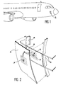
- FIG. 1 of the appended figures which represents in perspective the front of an airplane
- one S pressure taps intended to allow the static pressure measurement
- This plug type is usually located on the fuselage, in an aerodynamic flow zone with little disturbance.
- the pressure tapping device S includes a pressure tapping part 2 which present in the form of a disc pierced with holes, commonly called “pepper shaker".
- the pressure tapping device S is carried by a reinforcement element 3 which is fixed on the framework 4 forming the structure of the aircraft.
- a reinforcement element 3 which is fixed on the framework 4 forming the structure of the aircraft.
- the part of pressure tap 2 is then received in an opening circular 7 formed in the fuselage panel 5.
- the leveling operation performed after mounting the device S is a heavy operation industrially. Indeed, the tolerances being very low, this operation requires a lot of precision and therefore a lot of time. Yes it is poorly performed, the probe will deliver measurements which is not acceptable as we have already indicated.
- the subject of the invention is precisely a pressure sensing device for aircraft, the original design significantly improves quality measurements made by the probe, while rendering simpler and faster its installation on the fuselage panel, as well as its replacement possible.
- a pressure tapping device for aircraft comprising at least one element of reinforcement, a part of pressure tap carried by the reinforcing element and facing outwards from the aircraft, and a fuselage panel attached to the member reinforcement and provided with an opening in which is received the pressure tap part, device characterized in that it further comprises a plate in which is integrated, without discontinuity, the pressure tapping part, said plate being fixed on the reinforcing element and the opening having a shape and dimensions substantially identical to those of the plate, so that it is received in said opening and is flush with the surface exterior of the fuselage panel.
- the pressure tapping part is seamlessly integrated into a plate of relatively large dimensions, the continuity of the aerodynamic profile of the fuselage is ensured in the measurement area surrounding the grip part pressure, without any machining being necessary.
- this plate it becomes possible to fix this plate on the reinforcing element from outside the aircraft, in an opening in the fuselage panel, the shape and dimensions are adapted to those of the plate.
- This attachment method allows easy adjustment the plate so that its outer surface is flush with the exterior surface of the fuselage panel without requiring a leveling operation. Indeed, the outcrop tolerance is much less strict at the periphery of the plate only in the measurement area. A simpler and faster assembly is thus carried out.
- the replacement of a grip part pressure possibly damaged by impact is also simpler and faster.
- the reinforcing element has a recess in look of the opening formed in the panel fuselage, and the plate is embedded in this obviously.
- the recess advantageously has a bottom plane, against which a flat face of said plate.
- the pressure tapping part is constituted by a central region of the plate, crossed by perforations.
- the plate is then advantageously fixed on the reinforcing element by fixing members, such that, screws or bolts, which are all arranged to the periphery of the plate.
- the fasteners are are thus distant from the measurement zone located at near the pressure tapping part. That helps to guarantee the quality and accuracy of the measurement made by the probe.
- the fasteners are preferably placed outside an area angular air flow centered on said part pressure tap.
- This angular area of flow air without form fasteners preferably an angle of at least about 30 ° which coincides with the surface of the plate along which air flows in front of the part of pressure tap.
- the invention also relates to a method installation of a pressure tapping device on a fuselage panel of an aircraft, according to which fixes the fuselage panel to a reinforcing element, so that part of the pressure tap is received in an opening formed in said panel, the process being characterized in that one integrates, without discontinuity, the pressure tapping part at a substantially shaped and sized plate identical to those of said opening and in that said plate is fixed on the reinforcing element after to have fixed the fuselage panel on the element of reinforcement, so that the plate is received in said opening and is flush with the exterior surface of the fuselage.
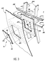
- the pressure tapping device comprises a plate 10 whose outer surface is intended to form a small part of the outer surface of the fuselage the aircraft.
- Plate 10 and the pressure tapping part 16 of the probe form thus a subset whose implantation on the aircraft fuselage will be described later. he it should be noted that the pressure tapping part 16 of the probe is integrated on plate 10 so that the outer surface thereof has no discontinuity other than perforations 14.
- the pressure measuring device further comprises a reinforcing element 18, intended to be fixed to the structure of the aircraft, of a manner which will be specified later as example.
- the pressure measurement device comprises a fuselage panel 20, also intended to be fixed to the structure of the aircraft.
- This fuselage panel 20 has a opening or window 22, fully located opposite of the reinforcing element 18. More specifically, the shape and the dimensions of the opening 22 are substantially identical to those on plate 10 (at games assembly) and the parts of panel 20 which surround this opening 22 are supported on the reinforcing element 18, so that it can be fixed to it by fasteners 24 such as rivets, screws or bolts, as shown in Figure 4. A fixing of the panel 20 by gluing can also be considered, without going beyond the ambit of the invention.
- the sub-assembly constituted by the plate 10 and the pressure tapping part 16 is located on the fuselage panel 20 from outside the aircraft, after the panel 20 has itself been mounted and fixed on the reinforcing element 18 by the fixing members 24. More specifically, the plate 10 is housed in the opening 22 as well as in a recess 26 formed in face of the opening 22 on the face of the element of reinforcement 18 facing outwards.
- the bottom of the recess 26 is advantageously flat, as is the rear face of the plate 10, which bears against said bottom.
- a hole 28 is formed in the center of the element of reinforcement 18, in the bottom of the recess 26 and opposite of the pressure tapping part 16.
- a hose 27 is connected to this hole 28, at the rear of the element reinforcement 18, to connect the grip part of pressure 16 at the probe (not shown).
- a device defrost 29 surrounds the hose 27, at the rear of the reinforcing element 18.
- shims of thickness 30 are advantageously interposed between the plate 10 and the reinforcing element 18, in the bottom of the recess 26, so that the outer surface of the plate 10 precisely and continuously flush with the surface exterior of the fuselage panel 20.
- the shims 30 may in particular be peelable shims of 0.05 mm per sheet. The arrangement obtained is such that the outer surfaces of plate 10 and panel 20 are perfectly aligned around the entire periphery of the plaque. It should be noted, however, that the distance separating the peripheral edge of the plate 10 from the pressure tapping part 16 is sufficient for the influence of a possible slight misalignment either practically without influence on the precision of the measured. This is why a leveling is not necessary.
- the plate 10 is generally fixed on the reinforcing element 18 by fixing members 32 such as screws or bolts. As shown in particularly Figure 4, these fasteners 32 are all arranged on the periphery of the plate 10, that is to say in a location as distant as possible perforations 14 forming the grip part pressure 16 of the probe.
- the fixing members 32 are placed outside an angular air flow zone 33 centered on the pressure tapping part 16 of the probe.
- This angular zone 33 is shown by hatching on Figure 4. It advantageously forms an angle of at least minus about 30 °.
- the angular zone 33 devoid of of fasteners 32 is centered on a line passing through the center of the pressure tapping part 16 and tilted up and back and forth.
- the fasteners 32 are omitted and the plate 10 is bonded to the reinforcing element 18. All the characteristics which have just been described ensure that the air flowing in front of the perforations 14 ensuring the taking of probe pressure experiences virtually no disturbance in its aerodynamic flow at near the pressure tapping part. Through therefore, quality and precision of measurement significantly higher than those obtained using existing measuring devices are ensured.
- plate 10 and opening 22 have rectangular outlines.
- contours of different shapes can be used without departing from the scope of the invention.
- the structure of the aircraft on which are fixed the reinforcing element 18 and the fuselage panel 20 usually present, in a known manner, under the form of a framework formed by circular frames 34 arranged in transverse planes of the aircraft and longitudinal angles 36 extending in the direction longitudinal of the aircraft.
- the device for taking pressure S is integrated in one of the delimited meshes between two adjacent frames 34 and between two angles 36 consecutive.
- the reinforcing element 18 is fixed to these frames 34 and angles 36 by some of the fixing members 24 also used to fix the fuselage panel 20 to the different elements of the framework.
- the invention is not limited to embodiment which has just been described as example, but covers all variants.
- the nature of the organs of attachment 24 and 32, their number and location may be different from those illustrated on Figure 4, without departing from the scope of the invention.
- the functional game that inevitably exists between the peripheral edge of the plate 10 and the outline of the opening 22 can be filled with a filler putty or any equivalent product.
- the element of reinforcement 18 may consist of a single piece, as shown in the figures, or several pieces able to take over all efforts arising from the presence of opening 22 in the panel 20.
- the fuselage panel 20 can be fixed on the reinforcing element 18 either by being attached to it by means of assembly any suitable, either by being made in one holding with said reinforcing element, for example in the case of a composite material panel or a metal panel in full machining.
Landscapes
- Engineering & Computer Science (AREA)
- Aviation & Aerospace Engineering (AREA)
- Physics & Mathematics (AREA)
- General Physics & Mathematics (AREA)
- Mechanical Engineering (AREA)
- Measuring Fluid Pressure (AREA)
- Connection Of Plates (AREA)
- Blow-Moulding Or Thermoforming Of Plastics Or The Like (AREA)
- Secondary Cells (AREA)
- Stored Programmes (AREA)
Abstract
Description
- la figure 1, déjà décrite, est une vue en perspective qui représente très schématiquement la partie avant du fuselage d'un avion ;
- la figure 2, déjà décrite, est une vue en perspective éclatée illustrant schématiquement l'implantation d'un dispositif de prise de pression sur un panneau de fuselage avant de l'avion de la figure 1, selon l'art antérieur ;
- la figure 3 est une vue en perspective illustrant schématiquement l'implantation d'un dispositif de prise de pression sur un panneau de fuselage d'un aéronef, conformément à l'invention ;
- la figure 4 est une vue de face d'un dispositif de prise de pression conforme à l'invention ; et
- la figure 5 est une vue en coupe selon la ligne V-V de la figure 4.
Claims (13)
- Dispositif de prise de pression pour aéronef, comprenant au moins un élément de renfort (18), une partie de prise de pression (16) portée par l'élément de renfort et tournée vers l'extérieur de l'aéronef, et un panneau de fuselage (20) fixé sur l'élément de renfort (18) et muni d'une ouverture (22) dans laquelle est reçue la partie de prise de pression (16), dispositif caractérisé en ce qu'il comprend de plus une plaque (10) dans laquelle est intégrée, sans discontinuité, la partie de prise de pression (16), ladite plaque étant fixée sur l'élément de renfort (18) et l'ouverture (22) présentant une forme et des dimensions sensiblement identiques à celles de la plaque, de telle sorte que celle-ci est reçue dans ladite ouverture et affleure la surface-extérieure du panneau de fuselage (20).
- Dispositif selon la revendication 1, dans lequel des cales d'épaisseur (30) sont interposées entre ladite plaque (10) et l'élément de renfort (18).
- Dispositif selon l'une quelconque des revendications 1 et 2, dans lequel l'élément de renfort (18) comporte un évidement (26) en regard de ladite ouverture (22), dans lequel est encastrée ladite plaque (10).
- Dispositif selon la revendication 3, dans lequel l'évidement (26) comporte un fond plan, contre lequel est appliquée une face plane de ladite plaque (10).
- Dispositif selon l'une quelconque des revendications 1 à 4, dans lequel la partie de prise de pression (16) est constituée par une région centrale de ladite plaque (10), traversée par des perforations (14).
- Dispositif selon l'une quelconque des revendications 1 à 5, dans lequel la plaque (10) est fixée sur l'élément de renfort (18) par des organes de fixation (32) tous disposés à la périphérie de ladite plaque.
- Dispositif selon la revendication 6, dans lequel les organes de fixation (32) sont disposés en dehors d'une zone angulaire d'écoulement d'air (33) centrée sur ladite partie de prise de pression (16).
- Dispositif selon la revendication 7, dans lequel la zone angulaire d'écoulement d'air (33) dépourvue d'organes de fixation (32) forme un angle d'au moins environ 30°.
- Procédé d'implantation d'un dispositif de prise de pression sur un panneau de fuselage (20) d'un aéronef, selon lequel on fixe le panneau de fuselage (20) sur un élément de renfort (18), de telle sorte qu'une partie de prise de pression (16) soit reçue dans une ouverture (22) formée dans ledit panneau, le procédé étant caractérisé en ce que l'on intègre, sans discontinuité, la partie de prise de pression (16) à une plaque (10) de forme et de dimensions sensiblement identiques à celles de ladite ouverture (22) et en ce que l'on fixe ladite plaque sur l'élément de renfort (18) après avoir fixé le panneau de fuselage (20) sur l'élément de renfort (18), de telle sorte que la plaque soit reçue dans ladite ouverture (22) et affleure la surface extérieure du fuselage.
- Dispositif selon la revendication 9, dans lequel on fixe ladite plaque (10) sur l'élément de renfort (18) en interposant des cales d'épaisseur (30) afin d'aligner la surface extérieure de la plaque sur celle du fuselage.
- Procédé selon l'une quelconque des revendications 9 et 10, dans lequel on fixe ladite plaque (10) sur l'élément de renfort (18) par des organes de fixation (32) tous disposés à la périphérie de la plaque.
- Dispositif selon la revendication 11, dans lequel on place les organes de fixation (32) en dehors d'une zone angulaire d'écoulement d'air (33) centrée sur la partie de prise de pression (16).
- Dispositif selon la revendication 12, dans lequel on place les organes de fixation (32) en dehors d'une zone angulaire d'écoulement d'air (33) formant un angle d'au moins environ 30°.
Applications Claiming Priority (2)
| Application Number | Priority Date | Filing Date | Title |
|---|---|---|---|
| FR0004831 | 2000-04-14 | ||
| FR0004831A FR2807737B1 (fr) | 2000-04-14 | 2000-04-14 | Dispositif de prise de pression et son procede d'implantation sur un panneau de fuselage d'aeronef |
Publications (2)
| Publication Number | Publication Date |
|---|---|
| EP1145952A1 true EP1145952A1 (fr) | 2001-10-17 |
| EP1145952B1 EP1145952B1 (fr) | 2005-12-21 |
Family
ID=8849263
Family Applications (1)
| Application Number | Title | Priority Date | Filing Date |
|---|---|---|---|
| EP01400945A Expired - Lifetime EP1145952B1 (fr) | 2000-04-14 | 2001-04-12 | Prise de pression et son montage sur un panneau du fuselage d'aéronef |
Country Status (6)
| Country | Link |
|---|---|
| US (1) | US6443390B2 (fr) |
| EP (1) | EP1145952B1 (fr) |
| AT (1) | ATE313481T1 (fr) |
| CA (1) | CA2343622C (fr) |
| DE (1) | DE60115981T2 (fr) |
| FR (1) | FR2807737B1 (fr) |
Cited By (6)
| Publication number | Priority date | Publication date | Assignee | Title |
|---|---|---|---|---|
| WO2005085065A1 (fr) * | 2004-02-27 | 2005-09-15 | Aerocontrolex Group | Appareil et procede pour applique de revetement a orifice statique |
| DE102011005355A1 (de) | 2011-03-10 | 2012-09-13 | Airbus Operations Gmbh | Komponentenanordnung an einer Luftfahrzeugstruktur und Verfahren zum Einbau einer Komponente in eine Luftfahrzeugsstruktur |
| FR2990191A1 (fr) * | 2012-05-04 | 2013-11-08 | Airbus Operations Sas | Agencement pour la fixation d'un dispositif de mesure sur une ouverture d'un panneau structural d'aeronef |
| EP2309100A3 (fr) * | 2009-10-06 | 2014-01-01 | Rolls-Royce plc | Procédé de formation d'un trou de mesure de la pression dans un composant d'une turbine à gaz |
| FR3010976A1 (fr) * | 2013-09-26 | 2015-03-27 | Airbus Operations Sas | Procede de montage de prises de pression sur la peau d'un aeronef |
| US11781574B2 (en) * | 2017-12-07 | 2023-10-10 | Premium Aerotec Gmbh | Probe fastening system and aircraft |
Families Citing this family (10)
| Publication number | Priority date | Publication date | Assignee | Title |
|---|---|---|---|---|
| US6672152B2 (en) * | 2001-12-21 | 2004-01-06 | Honeywell International Inc. | Flush surface air data sensor |
| FR2863185B1 (fr) * | 2003-12-04 | 2007-02-09 | Airbus France | Dispositif d'equipement d'un trou dans un panneau et panneau ainsi equipe |
| DE102004025381B4 (de) * | 2004-05-24 | 2014-01-23 | Airbus Operations Gmbh | Fensterrahmen für Flugzeuge |
| US20090000386A1 (en) * | 2005-03-11 | 2009-01-01 | Paradis Lawrence C | Fairing and installation methodology for sensor pressure belts |
| US7350752B2 (en) * | 2005-03-11 | 2008-04-01 | The Boeing Company | Fairing and installation methodology for sensor pressure belts |
| DE102006025388B4 (de) * | 2006-05-31 | 2009-10-29 | Airbus Deutschland Gmbh | Leitungssystemanordnung in einem einen Rumpf aufweisenden Luft- oder Raumfahrzeug |
| US8764000B2 (en) * | 2007-06-28 | 2014-07-01 | United Technologies Corporation | Tool alignment fixture |
| ES2349217B1 (es) * | 2007-12-28 | 2011-10-24 | Airbus Operations, S.L. | Sistema de integracion de tuercas remachables en piezas de plastico. |
| FR3129663B1 (fr) * | 2021-11-30 | 2023-12-08 | Airbus Operations Sas | Ensemble de reparation pour prise de pression statique d’aeronef. |
| GB2625375A (en) * | 2022-12-16 | 2024-06-19 | Raytheon Systems Ltd | Removable and reconfigurable plug breaks or feed through panels |
Citations (2)
| Publication number | Priority date | Publication date | Assignee | Title |
|---|---|---|---|---|
| GB2274170A (en) * | 1993-01-08 | 1994-07-13 | Short Brothers Plc | Aerodynamic pressure sensor system |
| US5616861A (en) * | 1995-06-07 | 1997-04-01 | Rosemount Aerospace Inc. | Three pressure pseudo -Δ-P sensor for use with three pressure air data probe |
Family Cites Families (4)
| Publication number | Priority date | Publication date | Assignee | Title |
|---|---|---|---|---|
| GB9320678D0 (en) * | 1993-10-07 | 1993-12-08 | Westland Helicopters | Static vent units |
| US5540406A (en) * | 1993-10-25 | 1996-07-30 | Occhipinti; Anthony C. | Hydrofoils and airfoils |
| GB9418575D0 (en) * | 1994-09-15 | 1994-11-02 | Westland Helicopters | Static vent units |
| US6042057A (en) * | 1998-03-19 | 2000-03-28 | The Boeing Company | Aerodynamically actuated magnetic ascent vent cover |
-
2000
- 2000-04-14 FR FR0004831A patent/FR2807737B1/fr not_active Expired - Fee Related
-
2001
- 2001-03-20 US US09/811,426 patent/US6443390B2/en not_active Expired - Lifetime
- 2001-04-10 CA CA002343622A patent/CA2343622C/fr not_active Expired - Fee Related
- 2001-04-12 DE DE60115981T patent/DE60115981T2/de not_active Expired - Lifetime
- 2001-04-12 EP EP01400945A patent/EP1145952B1/fr not_active Expired - Lifetime
- 2001-04-12 AT AT01400945T patent/ATE313481T1/de not_active IP Right Cessation
Patent Citations (2)
| Publication number | Priority date | Publication date | Assignee | Title |
|---|---|---|---|---|
| GB2274170A (en) * | 1993-01-08 | 1994-07-13 | Short Brothers Plc | Aerodynamic pressure sensor system |
| US5616861A (en) * | 1995-06-07 | 1997-04-01 | Rosemount Aerospace Inc. | Three pressure pseudo -Δ-P sensor for use with three pressure air data probe |
Cited By (16)
| Publication number | Priority date | Publication date | Assignee | Title |
|---|---|---|---|---|
| WO2005085065A1 (fr) * | 2004-02-27 | 2005-09-15 | Aerocontrolex Group | Appareil et procede pour applique de revetement a orifice statique |
| US7407136B2 (en) | 2004-02-27 | 2008-08-05 | Aerocontrolex Group, Inc. | Static port skin applique apparatus and method |
| US8764382B2 (en) | 2009-10-06 | 2014-07-01 | Rolls-Royce Plc | Method for forming a pressure measurement hole in a component |
| EP2309100A3 (fr) * | 2009-10-06 | 2014-01-01 | Rolls-Royce plc | Procédé de formation d'un trou de mesure de la pression dans un composant d'une turbine à gaz |
| WO2012119906A3 (fr) * | 2011-03-10 | 2013-05-23 | Airbus Operations Gmbh | Agencement de composant sur une structure d'aéronef, et procédé pour l'installation d'un composant dans une structure d'aéronef |
| WO2012119906A2 (fr) | 2011-03-10 | 2012-09-13 | Airbus Operations Gmbh | Agencement de composant sur une structure d'aéronef, et procédé pour l'installation d'un composant dans une structure d'aéronef |
| CN103547930A (zh) * | 2011-03-10 | 2014-01-29 | 空中客车德国运营有限责任公司 | 飞行器结构上的构件布置和构件安装到飞行器结构的方法 |
| DE102011005355A1 (de) | 2011-03-10 | 2012-09-13 | Airbus Operations Gmbh | Komponentenanordnung an einer Luftfahrzeugstruktur und Verfahren zum Einbau einer Komponente in eine Luftfahrzeugsstruktur |
| US9493247B2 (en) | 2011-03-10 | 2016-11-15 | Airbus Operations Gmbh | Component arrangement on an aircraft structure, and a method for the installation of a component into an aircraft structure |
| CN103547930B (zh) * | 2011-03-10 | 2016-11-23 | 空中客车德国运营有限责任公司 | 飞行器结构上的构件布置和构件安装到飞行器结构的方法 |
| FR2990191A1 (fr) * | 2012-05-04 | 2013-11-08 | Airbus Operations Sas | Agencement pour la fixation d'un dispositif de mesure sur une ouverture d'un panneau structural d'aeronef |
| FR3010976A1 (fr) * | 2013-09-26 | 2015-03-27 | Airbus Operations Sas | Procede de montage de prises de pression sur la peau d'un aeronef |
| US9546006B2 (en) | 2013-09-26 | 2017-01-17 | Airbus Operations Sas | Method of mounting pressure ports in the skin of an aircraft |
| US11781574B2 (en) * | 2017-12-07 | 2023-10-10 | Premium Aerotec Gmbh | Probe fastening system and aircraft |
| US20240044350A1 (en) * | 2017-12-07 | 2024-02-08 | Premium Aerotec Gmbh | Probe Fastening System And Aircraft |
| US12258996B2 (en) * | 2017-12-07 | 2025-03-25 | Premium Aerotec Gmbh | Probe fastening system and aircraft |
Also Published As
| Publication number | Publication date |
|---|---|
| DE60115981T2 (de) | 2006-08-24 |
| CA2343622C (fr) | 2009-06-23 |
| US20010030261A1 (en) | 2001-10-18 |
| FR2807737A1 (fr) | 2001-10-19 |
| EP1145952B1 (fr) | 2005-12-21 |
| US6443390B2 (en) | 2002-09-03 |
| ATE313481T1 (de) | 2006-01-15 |
| FR2807737B1 (fr) | 2002-07-12 |
| CA2343622A1 (fr) | 2001-10-14 |
| DE60115981D1 (de) | 2006-01-26 |
Similar Documents
| Publication | Publication Date | Title |
|---|---|---|
| EP1145952B1 (fr) | Prise de pression et son montage sur un panneau du fuselage d'aéronef | |
| EP1300333B1 (fr) | Dispositif de fixation d'un pare-brise d'aeronef | |
| FR2787410A1 (fr) | Face avant et agencement de cette face avant dans un vehicule automobile | |
| EP1314839A1 (fr) | Dispositif indicateur de défaut de fermeture pour nacelle de moteur d'avion | |
| EP2002131A1 (fr) | Ecrou pour la fixation d'un pare-brise d'aeronef et dispositif de fixation d'un pare-brise d'aeronef incorporant ledit ecrou | |
| EP2170685B1 (fr) | Procede de montage d'un pare-chocs sur une structure de vehicule automobile. | |
| EP3489764B1 (fr) | Construction pour cadran fragile | |
| EP1046967B1 (fr) | Procédé d'assemblage d'un cercle d'encageage dans une boîte de montre et cercle d'encageage satisfaisant à ce procédé | |
| EP2000382A1 (fr) | Cabine de conduite de train comprenant une verrière | |
| EP3996954B1 (fr) | Dispositif de fixation d'un enjoliveur de bord latéral de cadre de porte de véhicule automobile | |
| FR2860293A1 (fr) | Dispositif et procede pour mesure de parametres en essai de vol d'un aeronef | |
| EP3712712A1 (fr) | Cadran d'une piece d'horlogerie pourvu d'un decor tridimensionnel | |
| EP0517598B1 (fr) | Dispositif de fixation d'un organe d'éclairage ou de signalisation de véhicule automobile avec compensation de tolérances | |
| EP2431204B1 (fr) | Dispositif de basculement d'un pare-brise | |
| EP4431404B1 (fr) | Support amelioré pour la maintenance d'un radôme d'aeronef | |
| EP3476717B1 (fr) | Pare-brise d'aéronef avec une glace à bride intégrée et entretoises de transfert et répartition des charges | |
| EP1293379B1 (fr) | Agencement pour la fixation d'un élément d'équipement sur un élement de structure de caisse | |
| EP3621853B1 (fr) | Vitrage de vehicule comportant une embase de fixation d'accessoires a piece metallique et embase de fixation d'accessoires. | |
| EP2352657A1 (fr) | Porte de vehicule comprenant un enjoliveur, vehicule comprenant une telle porte et procede d'assemblage d'une telle porte | |
| FR2813272A1 (fr) | Ensemble de structure de caisse a montage rapide | |
| EP3505779B1 (fr) | Plaque en tôle métallique, portant une vis sans soudage | |
| EP1584516A1 (fr) | Ensemble de montage d'une barre de toit longitudinale sur un toit d'un véhicule automobile | |
| EP4185480B1 (fr) | Vitrage a porte-vitre fin et procede de fabrication dudit vitrage | |
| BE1014469A6 (fr) | Fixation de capteurs sur vitrages automobiles. | |
| FR2990191A1 (fr) | Agencement pour la fixation d'un dispositif de mesure sur une ouverture d'un panneau structural d'aeronef |
Legal Events
| Date | Code | Title | Description |
|---|---|---|---|
| PUAI | Public reference made under article 153(3) epc to a published international application that has entered the european phase |
Free format text: ORIGINAL CODE: 0009012 |
|
| AK | Designated contracting states |
Kind code of ref document: A1 Designated state(s): AT BE CH CY DE DK ES FI FR GB GR IE IT LI LU MC NL PT SE TR |
|
| AX | Request for extension of the european patent |
Free format text: AL;LT;LV;MK;RO;SI |
|
| 17P | Request for examination filed |
Effective date: 20020121 |
|
| AKX | Designation fees paid |
Free format text: AT BE CH CY DE DK ES FI FR GB GR IE IT LI LU MC NL PT SE TR |
|
| RAP1 | Party data changed (applicant data changed or rights of an application transferred) |
Owner name: AIRBUS FRANCE |
|
| GRAP | Despatch of communication of intention to grant a patent |
Free format text: ORIGINAL CODE: EPIDOSNIGR1 |
|
| GRAS | Grant fee paid |
Free format text: ORIGINAL CODE: EPIDOSNIGR3 |
|
| GRAA | (expected) grant |
Free format text: ORIGINAL CODE: 0009210 |
|
| AK | Designated contracting states |
Kind code of ref document: B1 Designated state(s): AT BE CH CY DE DK ES FI FR GB GR IE IT LI LU MC NL PT SE TR |
|
| PG25 | Lapsed in a contracting state [announced via postgrant information from national office to epo] |
Ref country code: AT Free format text: LAPSE BECAUSE OF FAILURE TO SUBMIT A TRANSLATION OF THE DESCRIPTION OR TO PAY THE FEE WITHIN THE PRESCRIBED TIME-LIMIT Effective date: 20051221 Ref country code: IE Free format text: LAPSE BECAUSE OF FAILURE TO SUBMIT A TRANSLATION OF THE DESCRIPTION OR TO PAY THE FEE WITHIN THE PRESCRIBED TIME-LIMIT Effective date: 20051221 Ref country code: NL Free format text: LAPSE BECAUSE OF FAILURE TO SUBMIT A TRANSLATION OF THE DESCRIPTION OR TO PAY THE FEE WITHIN THE PRESCRIBED TIME-LIMIT Effective date: 20051221 Ref country code: FI Free format text: LAPSE BECAUSE OF FAILURE TO SUBMIT A TRANSLATION OF THE DESCRIPTION OR TO PAY THE FEE WITHIN THE PRESCRIBED TIME-LIMIT Effective date: 20051221 |
|
| REG | Reference to a national code |
Ref country code: GB Ref legal event code: FG4D Free format text: NOT ENGLISH |
|
| REG | Reference to a national code |
Ref country code: CH Ref legal event code: EP |
|
| REG | Reference to a national code |
Ref country code: IE Ref legal event code: FG4D Free format text: LANGUAGE OF EP DOCUMENT: FRENCH |
|
| REF | Corresponds to: |
Ref document number: 60115981 Country of ref document: DE Date of ref document: 20060126 Kind code of ref document: P |
|
| PG25 | Lapsed in a contracting state [announced via postgrant information from national office to epo] |
Ref country code: GR Free format text: LAPSE BECAUSE OF FAILURE TO SUBMIT A TRANSLATION OF THE DESCRIPTION OR TO PAY THE FEE WITHIN THE PRESCRIBED TIME-LIMIT Effective date: 20060321 Ref country code: DK Free format text: LAPSE BECAUSE OF FAILURE TO SUBMIT A TRANSLATION OF THE DESCRIPTION OR TO PAY THE FEE WITHIN THE PRESCRIBED TIME-LIMIT Effective date: 20060321 |
|
| PG25 | Lapsed in a contracting state [announced via postgrant information from national office to epo] |
Ref country code: ES Free format text: LAPSE BECAUSE OF FAILURE TO SUBMIT A TRANSLATION OF THE DESCRIPTION OR TO PAY THE FEE WITHIN THE PRESCRIBED TIME-LIMIT Effective date: 20060401 |
|
| REG | Reference to a national code |
Ref country code: SE Ref legal event code: TRGR |
|
| GBT | Gb: translation of ep patent filed (gb section 77(6)(a)/1977) |
Effective date: 20060310 |
|
| PG25 | Lapsed in a contracting state [announced via postgrant information from national office to epo] |
Ref country code: CH Free format text: LAPSE BECAUSE OF NON-PAYMENT OF DUE FEES Effective date: 20060430 Ref country code: BE Free format text: LAPSE BECAUSE OF NON-PAYMENT OF DUE FEES Effective date: 20060430 Ref country code: LI Free format text: LAPSE BECAUSE OF NON-PAYMENT OF DUE FEES Effective date: 20060430 Ref country code: MC Free format text: LAPSE BECAUSE OF NON-PAYMENT OF DUE FEES Effective date: 20060430 |
|
| NLV1 | Nl: lapsed or annulled due to failure to fulfill the requirements of art. 29p and 29m of the patents act | ||
| REG | Reference to a national code |
Ref country code: IE Ref legal event code: FD4D |
|
| PLBE | No opposition filed within time limit |
Free format text: ORIGINAL CODE: 0009261 |
|
| STAA | Information on the status of an ep patent application or granted ep patent |
Free format text: STATUS: NO OPPOSITION FILED WITHIN TIME LIMIT |
|
| 26N | No opposition filed |
Effective date: 20060922 |
|
| REG | Reference to a national code |
Ref country code: CH Ref legal event code: PL |
|
| BERE | Be: lapsed |
Owner name: AIRBUS FRANCE Effective date: 20060430 |
|
| PG25 | Lapsed in a contracting state [announced via postgrant information from national office to epo] |
Ref country code: TR Free format text: LAPSE BECAUSE OF FAILURE TO SUBMIT A TRANSLATION OF THE DESCRIPTION OR TO PAY THE FEE WITHIN THE PRESCRIBED TIME-LIMIT Effective date: 20051221 Ref country code: LU Free format text: LAPSE BECAUSE OF NON-PAYMENT OF DUE FEES Effective date: 20060412 |
|
| PG25 | Lapsed in a contracting state [announced via postgrant information from national office to epo] |
Ref country code: CY Free format text: LAPSE BECAUSE OF FAILURE TO SUBMIT A TRANSLATION OF THE DESCRIPTION OR TO PAY THE FEE WITHIN THE PRESCRIBED TIME-LIMIT Effective date: 20051221 |
|
| PGFP | Annual fee paid to national office [announced via postgrant information from national office to epo] |
Ref country code: SE Payment date: 20100415 Year of fee payment: 10 |
|
| REG | Reference to a national code |
Ref country code: GB Ref legal event code: 732E Free format text: REGISTERED BETWEEN 20110721 AND 20110727 |
|
| REG | Reference to a national code |
Ref country code: FR Ref legal event code: CD Owner name: AIRBUS HOLDING, FR Effective date: 20110916 Ref country code: FR Ref legal event code: CJ Effective date: 20110916 Ref country code: FR Ref legal event code: TP Owner name: AIRBUS HOLDING, FR Effective date: 20110913 Ref country code: FR Ref legal event code: CA Effective date: 20110916 |
|
| PG25 | Lapsed in a contracting state [announced via postgrant information from national office to epo] |
Ref country code: PT Free format text: LAPSE BECAUSE OF FAILURE TO SUBMIT A TRANSLATION OF THE DESCRIPTION OR TO PAY THE FEE WITHIN THE PRESCRIBED TIME-LIMIT Effective date: 20051221 |
|
| REG | Reference to a national code |
Ref country code: SE Ref legal event code: EUG |
|
| REG | Reference to a national code |
Ref country code: DE Ref legal event code: R082 Ref document number: 60115981 Country of ref document: DE Representative=s name: HENKEL, BREUER & PARTNER, DE |
|
| REG | Reference to a national code |
Ref country code: DE Ref legal event code: R081 Ref document number: 60115981 Country of ref document: DE Owner name: AIRBUS OPERATIONS SAS, FR Free format text: FORMER OWNER: AIRBUS FRANCE, TOULOUSE, FR Effective date: 20120326 Ref country code: DE Ref legal event code: R082 Ref document number: 60115981 Country of ref document: DE Representative=s name: PATENTANWAELTE HENKEL, BREUER & PARTNER, DE Effective date: 20120326 |
|
| PG25 | Lapsed in a contracting state [announced via postgrant information from national office to epo] |
Ref country code: SE Free format text: LAPSE BECAUSE OF NON-PAYMENT OF DUE FEES Effective date: 20110413 |
|
| PGFP | Annual fee paid to national office [announced via postgrant information from national office to epo] |
Ref country code: DE Payment date: 20150421 Year of fee payment: 15 |
|
| REG | Reference to a national code |
Ref country code: FR Ref legal event code: PLFP Year of fee payment: 16 |
|
| PGFP | Annual fee paid to national office [announced via postgrant information from national office to epo] |
Ref country code: IT Payment date: 20160427 Year of fee payment: 16 |
|
| REG | Reference to a national code |
Ref country code: DE Ref legal event code: R119 Ref document number: 60115981 Country of ref document: DE |
|
| PG25 | Lapsed in a contracting state [announced via postgrant information from national office to epo] |
Ref country code: DE Free format text: LAPSE BECAUSE OF NON-PAYMENT OF DUE FEES Effective date: 20161101 |
|
| REG | Reference to a national code |
Ref country code: FR Ref legal event code: PLFP Year of fee payment: 17 |
|
| REG | Reference to a national code |
Ref country code: FR Ref legal event code: PLFP Year of fee payment: 18 |
|
| PG25 | Lapsed in a contracting state [announced via postgrant information from national office to epo] |
Ref country code: IT Free format text: LAPSE BECAUSE OF NON-PAYMENT OF DUE FEES Effective date: 20170412 |
|
| PGFP | Annual fee paid to national office [announced via postgrant information from national office to epo] |
Ref country code: FR Payment date: 20180420 Year of fee payment: 18 |
|
| PGFP | Annual fee paid to national office [announced via postgrant information from national office to epo] |
Ref country code: GB Payment date: 20180418 Year of fee payment: 18 |
|
| GBPC | Gb: european patent ceased through non-payment of renewal fee |
Effective date: 20190412 |
|
| PG25 | Lapsed in a contracting state [announced via postgrant information from national office to epo] |
Ref country code: GB Free format text: LAPSE BECAUSE OF NON-PAYMENT OF DUE FEES Effective date: 20190412 |
|
| PG25 | Lapsed in a contracting state [announced via postgrant information from national office to epo] |
Ref country code: FR Free format text: LAPSE BECAUSE OF NON-PAYMENT OF DUE FEES Effective date: 20190430 |