EP1145876A1 - Moter vehicle trailer coupling - Google Patents
Moter vehicle trailer coupling Download PDFInfo
- Publication number
- EP1145876A1 EP1145876A1 EP01108830A EP01108830A EP1145876A1 EP 1145876 A1 EP1145876 A1 EP 1145876A1 EP 01108830 A EP01108830 A EP 01108830A EP 01108830 A EP01108830 A EP 01108830A EP 1145876 A1 EP1145876 A1 EP 1145876A1
- Authority
- EP
- European Patent Office
- Prior art keywords
- ball rod
- recess
- shaft
- cross
- coupling
- Prior art date
- Legal status (The legal status is an assumption and is not a legal conclusion. Google has not performed a legal analysis and makes no representation as to the accuracy of the status listed.)
- Withdrawn
Links
Images


Classifications
-
- B—PERFORMING OPERATIONS; TRANSPORTING
- B60—VEHICLES IN GENERAL
- B60D—VEHICLE CONNECTIONS
- B60D1/00—Traction couplings; Hitches; Draw-gear; Towing devices
- B60D1/48—Traction couplings; Hitches; Draw-gear; Towing devices characterised by the mounting
- B60D1/54—Traction couplings; Hitches; Draw-gear; Towing devices characterised by the mounting collapsible or retractable when not in use, e.g. hide-away hitches
-
- B—PERFORMING OPERATIONS; TRANSPORTING
- B60—VEHICLES IN GENERAL
- B60D—VEHICLE CONNECTIONS
- B60D1/00—Traction couplings; Hitches; Draw-gear; Towing devices
- B60D1/01—Traction couplings or hitches characterised by their type
- B60D1/06—Ball-and-socket hitches, e.g. constructional details, auxiliary devices, their arrangement on the vehicle
Definitions
- the invention relates to a trailer hitch for motor vehicles with a ball rod, which is arbitrarily adjustable from a working position to a rest position, according to the preamble of the main claim.
- this ball rod that protrudes from the rear of the vehicle usually bothers, especially when maneuvering in a confined space, e.g. B. when parking.
- Hitching devices are therefore known, the ball rod of which can be removed. These devices have the disadvantage that the ball rod must be carried inside the vehicle or, if it therefore does not remain with the vehicle, is not immediately available.
- the cross bolt is screwed into a threaded bore arranged in the coupling carrier and is screwed in to lock the ball rod in the thread until the front end of the cross bolt hits the bottom of the recess.
- the cross bolt is unscrewed again until it emerges from the recess, after which the coupling rod can be rotated and moved. In the rest position, the coupling rod is then locked again by the same transverse bolt and engagement in a correspondingly arranged recess.
- This known device has the disadvantage that the bolt can loosen due to the natural vibrations of a motor vehicle and can unscrew itself, this unscrewing is supported by the cone at the free end of the cross bolt, which interacts with a corresponding cone band of the recess.
- forces act on the ball rod in the direction of the axis of the ball rod due to their work function forces also act radially outwards due to the cones in the axial direction of the cross bolt, which, in conjunction with the thread pitch of the cross bolt thread and the vehicle vibrations, cause the cross bolt to be unscrewed cause.
- the trailer hitch for motor vehicles has characteristic features of the main claim the advantage that they are a technically inexpensive and therefore represents economically producible solution. Because of their simple Manual operation is also neither during assembly nor during later operation relies on an energy source, still on Screwing work is also advantageous because of the small space required. A yourself independent release of the lock is excluded.
- the shaft the ball rod in a known manner (US-PS 2544185) one constant cross section.
- US-PS 2544185 a known manner
- a double axisymmetric, in particular a square cross section for the shaft of the ball rod there is also the advantage that the ball rod at Pulled out of the coupling carrier when not in use, by 90 ° twisted, i.e. with the ball pointing to the side, into the coupling carrier inserted and outside the bumper area can be locked.
- the ball bar in its unlocked state on its own axis rotatable by a in a manner known per se circular cross section used for the shaft of the ball rod becomes. This will allow the cranked end of the ball rod from its upright position by 90 ° without the To have to remove the ball rod from the coupling carrier, and in order then under the bumper or the rear of the vehicle slide and lock it again in the coupling bracket.
- the recess in the ball rod in a bore in particular a blind hole with a conical inlet.
- the cross bolt in the working position against axial adjustment in Coupling carrier and / or lockable in the recess.
- a thread for such an axial locking is provided on the cross bolt after further configuration of the Invention.
- such an additional locking device is to be used in the easiest way to be solvable, so that a quick and easy Adjustment is given.
- Cross bolt stepped with a cone on one step.
- This The cone interacts with a conical surface of the recess in the ball rod, so that there is a wedge effect.
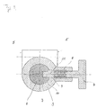
- FIG. 1 shows an embodiment of the invention Tow bar for motor vehicles, almost all claimed features in combination.
- Fig. 1 shows a Coupling in operating position. It essentially consists of one Ball rod 1, the cranked end of which carries a ball 2, and the Shaft is held by a clutch carrier 3. About the Handle 4 is operated a cross bolt not visible there, which in engages the not visible recess of the ball rod 1.
- the coupling bracket 3 is connected to the vehicle via the fastenings 5 firmly connected.
- Fig. 2 the rest position of the trailer coupling is shown. To is the cranked end of the ball rod 1 rotated by 90 ° and the Ball rod pushed forward in the direction of travel. This will make a Part of the shaft 6 of the ball bar visible in the Operating position had been in the clutch carrier 3.
- FIG. 3 shows a section along the line I - I in FIG. 1 the locking situation in which the cross pin 11 by pressing the Spring 8 is inserted into the recess 7 of the shaft 6, so that on the conical expansion 10 of the shaft 6, the conical Surface 9 of the cross pin 11 comes to rest.
- the spring 8 radially to the ball rod 1 outwards from the Recess 7 pulled so that the ball rod 1 rotates and / or can be moved, and the cross pin 11 in another not shown recess can be locked.
Abstract
Description
Die Erfindung geht aus von einer Anhängerkupplung für
Kraftfahrzeuge mit einer Kugelstange, die willkürlich aus einer
Arbeitsstellung in eine Ruhestellung verstellbar ist, nach der Gattung
des Hauptanspruches. Bei Nichtgebrauch stört in der Regel diese über
das Fahrzeugheck herausragende Kugelstange, vor allem beim
Rangieren auf engem Raum, z. B. beim Einparken.
Es sind daher Anhängevorrichtungen bekannt, deren Kugelstange
demontierbar ist. Diese Vorrichtungen haben den Nachteil, dass die
Kugelstange im Fahrzeuginneren mitgeführt werden muss oder, sofern
sie deswegen nicht beim Fahrzeug verbleibt, nicht unmittelbar zur
Verfügung steht.
Bei einer bekannten Anhängerkupplung der gattungsgemäßen Art
(US-PS 2544185) ist der Querbolzen in einer im Kupplungsträger
angeordneten Gewindebohrung eingeschraubt und wird zur
Verriegelung der Kugelstange im Gewinde hereingedreht, bis das
vordere Ende des Querbolzens auf den Boden der Ausnehmung stößt.
Zum Entriegelung wird der Querbolzen wieder herausgeschraubt bis er
aus der Ausnehmung taucht wonach die Kupplungsstange verdreht
und verschoben werden kann. In der Ruhelage wird dann durch
denselben Querbolzen und Eingreifen in einer entsprechend an
anderer Stelle angeordneten Ausnehmung die Kupplungsstange wieder
verriegelt. Diese bekannte Einrichtung hat den Nachteil, dass sich der
Bolzen aufgrund der natürlichen Erschütterungen eines
Kraftfahrzeuges lockern kann und selbsttätig herausschrauben kann,
wobei dieses von Hause aus herausschrauben unterstützt wird durch
den Konus am freien Ende des Querbolzens, der mit einem
entsprechenden Konusband der Ausnehmung zusammenwirkt. Sobald
aufgrund ihrer Arbeitsfunktion an der Kugelstange in Richtung der
Achse der Kugelstange wirkende Kräfte angreifen, entstehen auch
aufgrund der Koni in Achsrichtung des Querbolzens, und zwar radial
nach außen wirkende Kräfte, die in Verbindung mit der
Gewindesteigung des Querbolzensgewinde und den
Fahrzeugerschütterungen ein Herausdrehen des Querbolzens
bewirken. Außerdem ist es eine nicht unerhebliche Geduldsprobe, bei
Verstellen der Kupplung aus der Ruhestellung in die Arbeitsstellung
und umgekehrt jeweils die Ausnehmung mit dem Querbolzen zu
treffen, bzw. den Querbolzen herein- oder herauszuschrauben. Es ist
zwar bekannt, bei einer Anhängerkupplung einen Querbolzen zu
verwenden, der entgegen der Kraft einer Feder herausziehbar ist und
der Verriegelung einer verschwenkbaren Anhängerkupplung in
Arbeitsstellung bzw. Ruhestellung dient (GB-PS 1504643). Der
Nachteil dieser bekannten Kupplung besteht allerdings darin, dass sie
nicht nur konstruktiv äußerst aufwendig ist, sondern dass die Zuglast
dieser Anhängerkupplung über einen quer zur Fahrtrichtung
angeordneten, relativ dünnen Bolzen erfolgt, um den auch das die
Kugel der Anhängerkupplung tragende Teil verdrehbar ist. Ein weiterer
Nachteil dieser Anhängerkupplung besteht darin, dass aufgrund der
verdrehbaren Lagerung auf einem Bolzen und in Zugrichtung gesehen
dem Versatz dieses Bolzens zum Angriffspunkt an der Kugel je nach
Zugkraft erhebliche Hebelkräfte entstehen, die sich als Scherkräfte am
Querbolzen auswirken. Derartige einfache gegen Feder verschiebbare
Verriegelungen sind natürlich in der Technik vielfältig bekannt,
angefangen bei der Höhenverstellung eines Stuhles bis zu der
Anwendung bei Werkzeugmaschinen, beispielsweise Tischkreissägen
mit drehbarer Arbeitsplatte. Ein zusätzlicher Nachteil dieser
bekannten Kupplung besteht auch darin, dass mindestens zwei
derartige Querbolzen vorgesehen werden müssen, um eine
Querverspannung des verdrehbaren Teils im Kupplungsträger zu
vermeiden. Dieses führt nicht nur zu erheblichen Mehrkosten,
sondern vor allem zu einem Handlingproblem, weil beide Querbolzen
gleichzeitig herausgezogen werden müssen und der betätigenden
Person die dritte Hand fehlt, um die Verdrehung des verdrehbaren
Teiles vorzunehmen.The invention relates to a trailer hitch for motor vehicles with a ball rod, which is arbitrarily adjustable from a working position to a rest position, according to the preamble of the main claim. When not in use, this ball rod that protrudes from the rear of the vehicle usually bothers, especially when maneuvering in a confined space, e.g. B. when parking.
Hitching devices are therefore known, the ball rod of which can be removed. These devices have the disadvantage that the ball rod must be carried inside the vehicle or, if it therefore does not remain with the vehicle, is not immediately available.
In a known trailer coupling of the generic type (US-PS 2544185), the cross bolt is screwed into a threaded bore arranged in the coupling carrier and is screwed in to lock the ball rod in the thread until the front end of the cross bolt hits the bottom of the recess. To unlock, the cross bolt is unscrewed again until it emerges from the recess, after which the coupling rod can be rotated and moved. In the rest position, the coupling rod is then locked again by the same transverse bolt and engagement in a correspondingly arranged recess. This known device has the disadvantage that the bolt can loosen due to the natural vibrations of a motor vehicle and can unscrew itself, this unscrewing is supported by the cone at the free end of the cross bolt, which interacts with a corresponding cone band of the recess. As soon as forces act on the ball rod in the direction of the axis of the ball rod due to their work function, forces also act radially outwards due to the cones in the axial direction of the cross bolt, which, in conjunction with the thread pitch of the cross bolt thread and the vehicle vibrations, cause the cross bolt to be unscrewed cause. In addition, it is a not inconsiderable test of patience when the clutch is adjusted from the rest position to the working position and vice versa to hit the recess with the cross bolt or to screw the cross bolt in or out. It is known to use a cross bolt on a trailer hitch, which can be pulled out against the force of a spring and serves to lock a pivotable trailer hitch in the working position or rest position (GB-PS 1504643). The disadvantage of this known coupling, however, is that it is not only extremely complex in terms of construction, but that the tensile load of this trailer coupling is carried out via a relatively thin bolt arranged transversely to the direction of travel, about which the part carrying the ball of the trailer coupling can also be rotated. Another disadvantage of this trailer coupling is that due to the rotatable mounting on a bolt and seen in the direction of pull, the offset of this bolt to the point of application on the ball, depending on the pulling force, results in considerable leverage forces which act as shear forces on the cross bolt. Such simple spring-displaceable locks are of course widely known in the art, starting with the height adjustment of a chair up to use in machine tools, for example table saws with a rotating worktop. An additional disadvantage of this known coupling is that at least two cross bolts of this type must be provided in order to avoid transverse tensioning of the rotatable part in the coupling carrier. This not only leads to considerable additional costs, but above all to a handling problem, because both cross bolts have to be pulled out at the same time and the operator is missing the third hand in order to twist the rotatable part.
Die erfindungsgemäße Anhängerkupplung für Kraftfahrzeuge mit den kennzeichnenden Merkmalen des Hauptanspruchs hat demgegenüber den Vorteil, dass sie eine technisch wenig aufwendige und daher wirtschaftlich herstellbare Lösung darstellt. Wegen ihrer einfachen Handbedienung ist man zudem weder bei der Montage noch beim späteren Betrieb auf eine Energiequelle angewiesen, noch auf Schraubarbeiten Von Vorteil ist auch der geringe Platzbedarf. Ein sich selbständiges Lösen der Verriegelung ist ausgeschlossen.The trailer hitch for motor vehicles according to the has characteristic features of the main claim the advantage that they are a technically inexpensive and therefore represents economically producible solution. Because of their simple Manual operation is also neither during assembly nor during later operation relies on an energy source, still on Screwing work is also advantageous because of the small space required. A yourself independent release of the lock is excluded.
Nach einer vorteilhaften Ausgestaltung der Erfindung weist der Schaft der Kugelstange in an sich bekannter Weise (US-PS 2544185) einen gleichbleibenden Querschnitt auf. Damit wird eine einfache kraft- und formschlüssige Anordnung zwischen Kugelstange und Kupplungsträger möglich und auch eine einfache Verstellung der Kugelstange bei Nichtbenutzung aus der Arbeitsstellung in die Ruhestellung, also aus dem Stoßbereich der Stoßstange vorzunehmen. Bei Verwendung eines doppelt achsensymmetrischen, insbesondere eines quadratischen Querschnitts für den Schaft der Kugelstange ergibt sich darüber hinaus der Vorteil, dass die Kugelstange bei Nichtgebrauch aus dem Kupplungsträger herausgezogen, um 90° verdreht, also mit der Kugel zur Seite weisend, in den Kupplungsträger eingeschoben und außerhalb des Stoßbereichs der Stoßstange verriegelt werden kann.According to an advantageous embodiment of the invention, the shaft the ball rod in a known manner (US-PS 2544185) one constant cross section. This makes a simple force and form-fitting arrangement between ball rod and Coupling carrier possible and also easy adjustment of the Ball bar when not in use from the working position Rest position, i.e. from the bumper bumper area. When using a double axisymmetric, in particular a square cross section for the shaft of the ball rod there is also the advantage that the ball rod at Pulled out of the coupling carrier when not in use, by 90 ° twisted, i.e. with the ball pointing to the side, into the coupling carrier inserted and outside the bumper area can be locked.
Nach einer zusätzlichen vorteilhaften Ausgestaltung der Erfindung ist die Kugelstange in entriegeltem Zustand um ihre eigene Achse verdrehbar, indem in ebenfalls an sich bekannter Weise ein kreisrunder Querschnitt für den Schaft der Kugelstange verwendet wird. Damit wird es möglich, dass gekröpfte Ende der Kugelstange aus seiner aufrechten Position um 90° zu verdrehen, ohne die Kugelstange aus dem Kupplungsträger entfernen zu müssen, und um sie anschließend unter die Stoßstange oder das Fahrzeugheck zu schieben und dort im Kupplungsträger wieder zu verriegeln. According to an additional advantageous embodiment of the invention the ball bar in its unlocked state on its own axis rotatable by a in a manner known per se circular cross section used for the shaft of the ball rod becomes. This will allow the cranked end of the ball rod from its upright position by 90 ° without the To have to remove the ball rod from the coupling carrier, and in order then under the bumper or the rear of the vehicle slide and lock it again in the coupling bracket.
Nach einer weiteren vorteilhaften Ausgestaltung der Erfindung besteht die Ausnehmung in der Kugelstange in einer Bohrung insbesondere einer Sackbohrung mit konischem Einlauf.According to a further advantageous embodiment of the invention the recess in the ball rod in a bore in particular a blind hole with a conical inlet.
Nach einer zusätzlichen vorteilhaften Ausgestaltung der Erfindung ist der Querbolzen in Arbeitsstellung gegen axiales Verstellen im Kupplungsträger und/oder in der Ausnehmung arretierbar. Hierbei ist denkbar, dass am Querbolzen nach weiterer Ausgestaltung der Erfindung ein Gewinde für eine solche axiale Arretierung vorgesehen ist. Erfindungsgemäß soll eine solche zusätzliche Verriegelung in einfachster Weise lösbar sein, so dass ein schnelles und problemloses Verstellen gegeben ist.According to an additional advantageous embodiment of the invention the cross bolt in the working position against axial adjustment in Coupling carrier and / or lockable in the recess. Here is conceivable that on the cross bolt after further configuration of the Invention provided a thread for such an axial locking is. According to the invention, such an additional locking device is to be used in the easiest way to be solvable, so that a quick and easy Adjustment is given.
Nach einer weiteren vorteilhaften Ausgestaltung der Erfindung ist der Querbolzen gestuft ausgebildet mit einem Konus an einer Stufe. Dieser Konus wirkt zusammen mit einer konischen Fläche der Ausnehmung in der Kugelstange, so dass sich eine Keilwirkung ergibt.According to a further advantageous embodiment of the invention Cross bolt stepped with a cone on one step. This The cone interacts with a conical surface of the recess in the ball rod, so that there is a wedge effect.
Nach einer zusätzlichen vorteilhaften Ausgestaltung der Erfindung ist in an sich bekannter Weise am Schaft der Kugelstange eine zweite in Ruhlage mit dem Querbolzen korrespondierende Ausnehmung vorhanden.According to an additional advantageous embodiment of the invention in a known manner on the shaft of the ball rod in a second Rest position with the cross bolt corresponding recess available.
Weitergehende zusätzliche Vorteile und vorteilhafte Ausgestaltungen der Erfindung sind der nachfolgenden Beschreibung, der Zeichnung und den Ansprüchen entnehmbar. Further additional advantages and advantageous configurations the invention are the following description, the drawing and removable from the claims.
Ein Ausführungsbeispiel des Gegenstandes der Erfindung ist in der Zeichnung dargestellt und im folgenden näher beschrieben. Es zeigen:
- Fig. 1
- eine Anhängerkupplung für Kraftfahrzeuge in Betriebsposition,
- Fig. 2
- eine Anhängerkupplung in Ruheposition,
- Fig. 3
- einen Schnitt durch den Kupplungsträger quer zur Achse der Kugelstange und in Höhe des Querbolzens bzw. der Ausnehmung in der Kugelstange.
- Fig. 1
- a trailer hitch for motor vehicles in the operating position,
- Fig. 2
- a trailer hitch in the rest position,
- Fig. 3
- a section through the coupling carrier transverse to the axis of the ball rod and at the level of the cross bolt or the recess in the ball rod.
In Fig. 1 ist eine Ausführungsform der erfindungsgemäßen
Anhängerkupplung für Kraftfahrzeuge dargestellt, die fast alle
beanspruchten Merkmale in Kombination darstellt. Fig. 1 zeigt eine
Kupplung in Betriebsposition. Sie besteht im wesentlichen aus einer
Kugelstange 1, deren abgekröpftes Ende eine Kugel 2 trägt, und deren
Schaft von einem Kupplungsträger 3 gehalten wird. Über das
Handgriff 4 wird ein dort nicht sichtbarer Querbolzen bedient, der in
die ebenfalls nicht sichtbare Ausnehmung der Kugelstange 1 eingreift.
Über die Befestigungen 5 ist der Kupplungsträger 3 mit dem Fahrzeug
fest verbunden. 1 shows an embodiment of the invention
Tow bar for motor vehicles, almost all
claimed features in combination. Fig. 1 shows a
Coupling in operating position. It essentially consists of one
Ball rod 1, the cranked end of which carries a
In Fig. 2 ist die Ruheposition der Anhängekupplung dargestellt. Dazu
ist das gekröpfte Ende der Kugelstange 1 um 90° verdreht und die
Kugelstange in Fahrtrichtung nach vorne geschoben. Dadurch wird ein
Teil des Schaftes 6 der Kugelstange sichtbar, der in der
Betriebsposition im Kupplungsträger 3 gelegen hatte.In Fig. 2 the rest position of the trailer coupling is shown. To
is the cranked end of the ball rod 1 rotated by 90 ° and the
Ball rod pushed forward in the direction of travel. This will make a
Part of the
Fig. 3 zeigt einen Schnitt entlang der Linie I - I in Fig. 1. Dargestellt ist
die Verriegelungssituation, in der der Querbolzen 11 durch Druck der
Feder 8 in die Ausnehmung 7 des Schaftes 6 eingeschoben wird, so
daß auf der konischen Aufweitung 10 des Schaftes 6 die konische
Fläche 9 des Querbolzens 11 zu liegen kommt. Zum Lösen der
Verriegelung wird der Querbolzen 11 am Handgriff 4 gegen die Kraft
der Feder 8 radial zur Kugelstange 1 nach außen aus der
Ausnehmung 7 gezogen, so daß die Kugelstange 1 verdreht und/oder
verschoben werden kann, und der Querbolzen 11 in eine weiteren
nicht dargestellten Ausnehmung eingerastet werden kann.FIG. 3 shows a section along the line I - I in FIG. 1
the locking situation in which the
Alle in der Beschreibung, den nachfolgenden Ansprüchen und der Zeichnung dargestellten Merkmale können sowohl einzeln als auch in beliebiger Kombination miteinander erfindungswesentlich sein. All in the description, the following claims and the Features shown in the drawing can be used both individually and in any combination with each other be essential to the invention.
- 11
- KugelstangeBall rod
- 22nd
- KugelBullet
- 33rd
- KupplungsträgerClutch carrier
- 44th
- HandgriffHandle
- 55
- BefestigungAttachment
- 66
- Schaftshaft
- 77
- AusnehmungRecess
- 88th
- Federfeather
- 99
- Konische Fläche des QuerbolzensConical surface of the cross bolt
- 1010th
- Konische AufweitungConical widening
- 1111
- QuerbolzenCross bolt
Claims (8)
Applications Claiming Priority (2)
| Application Number | Priority Date | Filing Date | Title |
|---|---|---|---|
| DE10017320 | 2000-04-10 | ||
| DE10017320 | 2000-04-10 |
Publications (1)
| Publication Number | Publication Date |
|---|---|
| EP1145876A1 true EP1145876A1 (en) | 2001-10-17 |
Family
ID=7637914
Family Applications (1)
| Application Number | Title | Priority Date | Filing Date |
|---|---|---|---|
| EP01108830A Withdrawn EP1145876A1 (en) | 2000-04-10 | 2001-04-09 | Moter vehicle trailer coupling |
Country Status (2)
| Country | Link |
|---|---|
| EP (1) | EP1145876A1 (en) |
| DE (1) | DE10117656A1 (en) |
Cited By (1)
| Publication number | Priority date | Publication date | Assignee | Title |
|---|---|---|---|---|
| NL1026198C2 (en) | 2004-05-14 | 2005-11-15 | Brink Internat B V | Rotatable towbar. |
Families Citing this family (5)
| Publication number | Priority date | Publication date | Assignee | Title |
|---|---|---|---|---|
| DE10329622A1 (en) * | 2003-06-26 | 2005-01-20 | Oris Fahrzeugteile Hans Riehle Gmbh | Towing |
| DE10342915B4 (en) * | 2003-09-15 | 2015-05-13 | Volkswagen Ag | Hitch for motor vehicles |
| DE50302794D1 (en) * | 2003-11-05 | 2006-05-18 | Cramer Kupplung Gmbh & Co Kg | ball coupling |
| DE102016204846A1 (en) | 2016-03-23 | 2017-09-28 | Volkswagen Aktiengesellschaft | Adjustable hitch assembly, vehicle, and method for adjusting an adjustable hitch assembly |
| CN112475807A (en) * | 2020-11-20 | 2021-03-12 | 杭州瑞诺机械有限公司 | Aluminum alloy trailer rod processing technology |
Citations (5)
| Publication number | Priority date | Publication date | Assignee | Title |
|---|---|---|---|---|
| US2544185A (en) | 1948-05-18 | 1951-03-06 | Frank T Sargent | Trailer hitch |
| FR2287353A2 (en) * | 1972-12-18 | 1976-05-07 | Gumuchian Pierre | Retractable vehicle trailer hitch - is locked in position by spring-loaded pin |
| GB1504643A (en) | 1976-08-12 | 1978-03-22 | Knapp K | Towing coupling assembly |
| EP0151099A2 (en) * | 1984-01-25 | 1985-08-07 | Släpvagnskopplingar Ab | A coupling device for a vehicle |
| DE20003480U1 (en) * | 2000-02-25 | 2000-05-31 | Sauermann Hans | Trailer coupling for a vehicle, in particular for a passenger car |
-
2001
- 2001-04-09 EP EP01108830A patent/EP1145876A1/en not_active Withdrawn
- 2001-04-09 DE DE10117656A patent/DE10117656A1/en not_active Withdrawn
Patent Citations (5)
| Publication number | Priority date | Publication date | Assignee | Title |
|---|---|---|---|---|
| US2544185A (en) | 1948-05-18 | 1951-03-06 | Frank T Sargent | Trailer hitch |
| FR2287353A2 (en) * | 1972-12-18 | 1976-05-07 | Gumuchian Pierre | Retractable vehicle trailer hitch - is locked in position by spring-loaded pin |
| GB1504643A (en) | 1976-08-12 | 1978-03-22 | Knapp K | Towing coupling assembly |
| EP0151099A2 (en) * | 1984-01-25 | 1985-08-07 | Släpvagnskopplingar Ab | A coupling device for a vehicle |
| DE20003480U1 (en) * | 2000-02-25 | 2000-05-31 | Sauermann Hans | Trailer coupling for a vehicle, in particular for a passenger car |
Cited By (2)
| Publication number | Priority date | Publication date | Assignee | Title |
|---|---|---|---|---|
| NL1026198C2 (en) | 2004-05-14 | 2005-11-15 | Brink Internat B V | Rotatable towbar. |
| WO2005110781A1 (en) | 2004-05-14 | 2005-11-24 | Thule Towing Systems B.V. | Rotatable tow hitch for a vehicle |
Also Published As
| Publication number | Publication date |
|---|---|
| DE10117656A1 (en) | 2002-01-03 |
Similar Documents
| Publication | Publication Date | Title |
|---|---|---|
| EP0380974B2 (en) | Grinding machine with an adaptator for the clamping of a supplementary tool | |
| EP1671527A1 (en) | Connecting element | |
| DE112009001605T5 (en) | Radially expandable bolt arrangement | |
| DE10147588A1 (en) | Fastening block for holding objects on a profile rail | |
| DE102012200462A1 (en) | expansion anchor | |
| DE202004014423U1 (en) | Device for mounting a motor vehicle clutch | |
| EP1952947B1 (en) | Hand-held power driven tool for drilling and/or screwing | |
| DE3642153A1 (en) | PORTABLE HAND TOOL, IN PARTICULAR ANGLE GRINDERS | |
| DE3831807C2 (en) | ||
| DE3228646C2 (en) | Parallel vice with device for idling displacement of the movable clamping jaw | |
| EP1259357A1 (en) | Machine tool | |
| EP1145876A1 (en) | Moter vehicle trailer coupling | |
| LU80698A1 (en) | MECHANICAL FASTENERS AND RELATED FASTENING TOOL | |
| DE4202046A1 (en) | Impact absorber for vehicle bumper - has bolt to adjust gap between bodywork and bumper fixing point | |
| DE3442514A1 (en) | Trailer coupling for vehicles, in particular motor vehicles for passenger transport | |
| EP1782972A1 (en) | Trailer hitch for a towing vehicle, especially for an agricultural tractor | |
| DE102016006340B4 (en) | Hole saw device with ejector | |
| DE2816908A1 (en) | AXLE BOLT CONNECTION | |
| DE102014221741B4 (en) | Swivel module of a trailer hitch | |
| DE10260493A1 (en) | Power chuck and release key for it | |
| DE3316954C2 (en) | ||
| DE102019109398B4 (en) | trailer hitch | |
| EP1634774B1 (en) | Load carrier for retractable hitch | |
| DE19837147C5 (en) | Chucks for machine tools | |
| CH656569A5 (en) | CLAMPING DEVICE FOR FASTENING A TOOL HOLDER TO A TOOL SPINDLE. |
Legal Events
| Date | Code | Title | Description |
|---|---|---|---|
| PUAI | Public reference made under article 153(3) epc to a published international application that has entered the european phase |
Free format text: ORIGINAL CODE: 0009012 |
|
| AK | Designated contracting states |
Kind code of ref document: A1 Designated state(s): AT BE CH CY DE DK ES FI FR GB GR IE IT LI LU MC NL PT SE TR |
|
| AX | Request for extension of the european patent |
Free format text: AL;LT;LV;MK;RO;SI |
|
| AKX | Designation fees paid | ||
| REG | Reference to a national code |
Ref country code: DE Ref legal event code: 8566 |
|
| STAA | Information on the status of an ep patent application or granted ep patent |
Free format text: STATUS: THE APPLICATION IS DEEMED TO BE WITHDRAWN |
|
| 18D | Application deemed to be withdrawn |
Effective date: 20020418 |