EP1144247B1 - Balloon trajectory control system - Google Patents
Balloon trajectory control system Download PDFInfo
- Publication number
- EP1144247B1 EP1144247B1 EP99931918A EP99931918A EP1144247B1 EP 1144247 B1 EP1144247 B1 EP 1144247B1 EP 99931918 A EP99931918 A EP 99931918A EP 99931918 A EP99931918 A EP 99931918A EP 1144247 B1 EP1144247 B1 EP 1144247B1
- Authority
- EP
- European Patent Office
- Prior art keywords
- lift
- balloon
- trajectory
- generating device
- tether
- Prior art date
- Legal status (The legal status is an assumption and is not a legal conclusion. Google has not performed a legal analysis and makes no representation as to the accuracy of the status listed.)
- Expired - Lifetime
Links
- 238000000034 method Methods 0.000 claims description 17
- 230000000087 stabilizing effect Effects 0.000 claims description 5
- 230000008901 benefit Effects 0.000 abstract description 10
- 230000010006 flight Effects 0.000 abstract description 3
- 238000013459 approach Methods 0.000 description 9
- 241000272517 Anseriformes Species 0.000 description 7
- 238000013461 design Methods 0.000 description 7
- 239000007789 gas Substances 0.000 description 6
- 239000000356 contaminant Substances 0.000 description 5
- 230000000694 effects Effects 0.000 description 5
- 239000001307 helium Substances 0.000 description 5
- 229910052734 helium Inorganic materials 0.000 description 5
- SWQJXJOGLNCZEY-UHFFFAOYSA-N helium atom Chemical compound [He] SWQJXJOGLNCZEY-UHFFFAOYSA-N 0.000 description 5
- 230000007935 neutral effect Effects 0.000 description 5
- 239000003381 stabilizer Substances 0.000 description 5
- 239000003507 refrigerant Substances 0.000 description 4
- 230000008859 change Effects 0.000 description 3
- 230000002349 favourable effect Effects 0.000 description 3
- 239000007788 liquid Substances 0.000 description 3
- 230000033001 locomotion Effects 0.000 description 3
- 230000001141 propulsive effect Effects 0.000 description 3
- 229920006328 Styrofoam Polymers 0.000 description 2
- 238000007664 blowing Methods 0.000 description 2
- 238000002485 combustion reaction Methods 0.000 description 2
- 230000003247 decreasing effect Effects 0.000 description 2
- 238000002474 experimental method Methods 0.000 description 2
- 239000000446 fuel Substances 0.000 description 2
- 230000005484 gravity Effects 0.000 description 2
- 239000000463 material Substances 0.000 description 2
- 238000005259 measurement Methods 0.000 description 2
- 238000012986 modification Methods 0.000 description 2
- 230000004048 modification Effects 0.000 description 2
- 239000008261 styrofoam Substances 0.000 description 2
- 241000557626 Corvus corax Species 0.000 description 1
- 229920000271 Kevlar® Polymers 0.000 description 1
- 238000004458 analytical method Methods 0.000 description 1
- 238000004891 communication Methods 0.000 description 1
- 238000010276 construction Methods 0.000 description 1
- 238000010001 crabbing Methods 0.000 description 1
- 230000001351 cycling effect Effects 0.000 description 1
- 230000003111 delayed effect Effects 0.000 description 1
- 238000010586 diagram Methods 0.000 description 1
- 238000007599 discharging Methods 0.000 description 1
- 238000005516 engineering process Methods 0.000 description 1
- 239000004744 fabric Substances 0.000 description 1
- 238000007667 floating Methods 0.000 description 1
- 239000012530 fluid Substances 0.000 description 1
- 238000010348 incorporation Methods 0.000 description 1
- 239000004761 kevlar Substances 0.000 description 1
- 239000003562 lightweight material Substances 0.000 description 1
- 238000004519 manufacturing process Methods 0.000 description 1
- 230000007246 mechanism Effects 0.000 description 1
- 238000013021 overheating Methods 0.000 description 1
- 238000011160 research Methods 0.000 description 1
- 230000029058 respiratory gaseous exchange Effects 0.000 description 1
- 239000011343 solid material Substances 0.000 description 1
- 239000005437 stratosphere Substances 0.000 description 1
- 239000000725 suspension Substances 0.000 description 1
- 239000005436 troposphere Substances 0.000 description 1
- 238000013022 venting Methods 0.000 description 1
- 239000003039 volatile agent Substances 0.000 description 1
- 239000002918 waste heat Substances 0.000 description 1
Images


Classifications
-
- B—PERFORMING OPERATIONS; TRANSPORTING
- B64—AIRCRAFT; AVIATION; COSMONAUTICS
- B64B—LIGHTER-THAN AIR AIRCRAFT
- B64B1/00—Lighter-than-air aircraft
Definitions
- the present invention relates to a method of controlling a trajectory of a lighter-than-air system and to a control device for a lighter-than-air system.
- the present invention relates generally to controlling the trajectory of a balloon and more specifically to a control device located remotely from a balloon for providing desired forces for trajectory control.
- Propellers require substantial power to drag a balloon through the atmosphere.
- the air has very low density at the high altitudes typically required of scientific balloons. At these high altitudes, propellers must be quite large in order to generate substantial lift. Also, significant amounts of power are typically unavailable for balloon systems due to the inherent need to keep weight to a minimum. If the power is generated using solar cells, then nighttime operation is not possible without very heavy batteries. If combustion provides the propulsive power, then the duration is limited by the weight of portable fuel. These requirements for propulsive power are at odds with the need to keep the weight low.
- Both the propeller-driven balloon and the propeller-driven airship described above were designed to maintain the position of an LTA vehicle above a specific point on the ground. Such operation requires the LTA vehicle to fly at a relative speed equal to the wind speed at the operating altitude. Since winds can have speeds in the range 15-50 m/s (50-150 ft/s), this leads to significant power requirements.
- An alternative approach is to control the altitude of an LTA vehicle to select an altitude at which the wind is moving in a favorable direction (or at least close to a desired direction).
- This is the main trajectory control technique used by sport balloonists with either hot-air balloons or helium balloons. Selecting altitudes at which the balloon will float in order to select different drift directions also has many drawbacks.
- some means of controlling altitude must be provided. Operators of hot air sport balloons can raise or lower the temperature of the lifting gas to adjust altitude, while operators of helium balloons tend to alternate between dropping ballast weight and venting lifting gas. This use of consumables ultimately limits the duration of the mission. Furthermore, carrying the ballast reduces the weight available for the payload.
- a drag device such as a parachute
- a parachute can be deployed a significant altitude below a balloon where the winds will usually be blowing in a different direction.
- This approach can be used to generate a force that will cause the balloon to move relative to the surrounding air.
- the direction of the force is restricted essentially to the direction the wind is blowing at the altitude of the parachute. It is possible to use a winch to raise or lower the parachute to altitudes with different wind directions, but this may require a significant amount of time for changing the direction of the force.
- a significant amount of power may be required to raise such a device in the presence of both gravity and aerodynamic drag.
- good knowledge of the wind distribution with altitude is required.
- a method of controlling a trajectory of a lighter-than-air system comprising: connecting a lift-generating device to the lighter-than-air system with a tether so that the lift-generating device passively generates lift from the airflow and the tether transmits a corresponding force to the lighter-than-air system.
- a trajectory-control device for a lighter-than-air system
- the trajectory-control device comprising: a lift-generating device; and, a tether for connecting the lift-generating device to a said lighter-than-air system, wherein the lift-generating device generates lift passively from the airflow and the tether transmits a corresponding force to the lighter-than-air system.
- the preferred embodiment provides an efficient force-generating device to control the trajectory of a balloon.
- the force-generating device should preferably be oriented so that the lift force is predominantly horizontal and transverse to the motion of the balloon.
- the preferred embodiment provides a balloon control device that passively exploits natural wind conditions, permits the balloon to remain at a fixed altitude and induces air flow past the balloon to sweep away contaminants.
- the preferred embodiment provides a device which requires very little power and can be operated efficiently at night.
- the preferred embodiment provides a system that includes a lift-generating device arranged to provide most of its lift in a horizontal direction, suspended from a balloon or other lighter-than-air system on a tether.
- the system may also include a flap or rudder for the purpose of changing the lift generated by the lift-generating device.
- the lift-generating device and flap (or rudder) may be mounted on a frame, such as a boom, or else integrally joined.
- the flap may operate to change the lift generated by the lift-generating device by means of a change in orientation or motion of the lift-generating device.
- the tether is preferably sufficiently long so as to take advantage of natural wind differences with altitude.
- the preferred embodiment uses very little power to operate, can operate at night, can be made of very lightweight materials, does not require detailed knowledge of the wind field, allows the balloon to remain at a fixed altitude, generates control forces having a greater range of magnitude and direction as compared with a comparably sized drag device, can change the direction of the control force fairly rapidly, and operates at an altitude lower than the balloon where the air density is greater so that the device can be relatively small compared with the balloon.
- Another advantage relates to the support of scientific instruments.
- Some very sensitive science instruments measure trace gases in the atmosphere at very low concentrations of a few parts per billion. Contaminants from the balloon itself, such as the helium lifting gas, or volatiles from the envelope material, can interfere with these sensitive measurements.
- a typical balloon drifts along with the local air mass and these contaminants accumulate in the vicinity of the balloon and gondola. Even a small relative airflow, such as would be caused by operation of the trajectory control device, will sweep away these contaminants and provide a fresh flow of air samples to the science instruments.
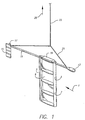
- the main lift-generating element is a wing 1 comprising a leading edge spar 3, a trailing edge spar 5, and a plurality of ribs 7.
- the leading edge spar 3, trailing edge spar 5 and ribs 7 support skin 9.
- the wing 1 is attached to a boom 11 having a front end and a back end.
- a counterweight 13 is attached to the front end of the boom 11.
- a rudder 15 and rudder actuator 17 are attached to the back end of the boom.
- a control module 19 is mounted at a convenient location on the device.
- the control module includes a power source (not shown), if required, comprising a battery and a solar panel.
- a yoke 21 connects the boom 11 to a tether 23.
- the upper end of the tether is attached to a winch 25 (not shown) mounted to an LTA system (e.g. a gondola of a balloon).
- the balloon trajectory control device shown in Fig 1 is lowered from the LTA vehicle such as a gondola of a floating balloon on the tether 23 that is relatively long.
- the length of the tether 23 may be several kilometers.
- the reason for the long tether 23 is to place the trajectory control device in a portion of the atmosphere at which the wind has a significantly different velocity (speed or direction) from the wind at the altitude of the balloon.
- Typical wind profiles are shown in Fig. 30.1 in "A Comparison of Several Very High Altitude Station Keeping Balloon Concepts" by J.J. Vorachek, cited above.
- the tether 23 is unwound from a spool using the winch 25 mounted on the LTA vehicle.
- the winch 25 may be powered or it may simply provide a passive means of lowering the trajectory control device at an acceptable rate, with the weight of the trajectory control device serving to pull out the tether 23. In the latter case, the trajectory control device may be discarded at the end of the flight by severing the tether 23 and providing a parachute for the device to control its rate of descent.
- the winch 25 is powered, it may be used to raise or lower the trajectory control device as desired to reach favorable altitudes or to restow the device. If used with a sport balloon, the winch 25 may be operated manually, or even eliminated. Under some conditions, the device could be hauled up hand-over-hand.
- the tether 23 may be a rope or a cable, for example, woven Kevlar thread. More generally the tether 23 may be a non-rigid mechanical connection, for example, a chain which is comprised of rigid links. A completely rigid tether may place severe structural limitations on the length of the tether because of the weight of components.
- the boom 11 may be a simple rigid member used for mounting the components of the system; more generally, this function could be accomplished by a frame, not necessarily rigid, suitable for this purpose.
- the rudder 15 may be a simple rigid member used for changing the orientation of the system; more generally, this function could be accomplished by a flap suitable for this purpose.
- the angle of attack of a lifting surface is defined as the angle between the relative wind and a reference chord line (i.e., a line running from the leading edge to the trailing edge of the wing).
- a reference chord line i.e., a line running from the leading edge to the trailing edge of the wing.
- the angle of attack of the wing 1 is adjusted by setting the angle of the rudder 15 by means of the rudder actuator 17 under the control of the control module 19.
- This arrangement of a small control surface behind a large lifting surface is very analogous to the arrangement of the wing and stabilizer/elevator for an aircraft. It is also very similar to the arrangement of the keel and rudder of a sailboat.
- the center of mass of the suspended device In order to keep the wing 1 operating in a stable attitude, the center of mass of the suspended device must be somewhat ahead of the aerodynamic neutral point defined analogously to the neutral point of an aircraft. If the suspension point, which will in essence be directly over the center of mass, is too far back, then the assembly will swing around, perhaps going tail first, or crabbing along sideways with the wing stalled aerodynamically. Although this is not the primary intended mode of operating, it might actually be an advantageous state for certain wind conditions in which a large drag force is in the desired direction. A moving mass may be incorporated into the design of the device to adjust the center of mass so as to induce this kind of behavior.
- the center of mass should be sufficiently far forward, thereby necessitating the counterweight 13. Since LTA vehicles usually have severe weight constraints, it is undesirable to add "dead" weight. For this reason, the control module 19, which may constitute a significant fraction of the total weight, may be positioned somewhat ahead of the lift-generating device and serve additional duty as a counterweight. However, as for an aircraft, moving the center of mass too far forward will reduce the ability of the rudder to control the angle of attack of the main wing 1. It is desirable for the center of mass to be placed in the same range as for subsonic aircraft.
- the center of mass typically is placed within the approximate range of 5% to 15% of the mean wing chord ahead of the neutral point.
- the prediction of the neutral point location is somewhat involved, but the procedure is generally known to those of ordinary skill and is available from numerous references.
- the longitudinal stability for aircraft can be found in "Aerodynamics, Aeronautics, and Flight Mechanics," by B.W. McCormick, Wiley 1979 on pages 479-483, incorporated herein by reference.
- the wing and horizontal stabilizer of the aircraft are analogous to the wing 1 and rudder 15 of the trajectory control device.
- the lateral component of the force from the tether 23 is analogous to the weight of the aircraft when the pitching moment equations are developed.
- a canard configuration could be used in the trajectory control device.
- the smaller stabilizing surface is placed ahead of the main lifting surface. This is discussed more fully below.
- control module 19 may receive commands from the balloon gondola by radio or by other communication means. Alternatively, the control module 19 may be preprogrammed prior to launch of the balloon system.
- trajectory control device can be operated in different modes with more or less complexity depending on the desired degree of trajectory control. For example, if the purpose is simply to provide a bias airflow past the supporting balloon to sweep away contaminants to improve the performance of sensitive instruments, then the rudder 15 could be set at a fixed angle before the flight. This fixed angle could be selected based on a desired relative velocity coupled with prior knowledge of the expected winds at the altitudes of the balloon and the wing 1.
- the prevailing winds typically are in a generally easterly or westerly direction depending on the season.
- a long duration balloon may go around the earth several times.
- the angle could be preset before launch based on the known prevailing winds and the desired drift direction.
- a left-zero-right control scheme may be adequate.
- the pilot could send a command to the device corresponding to maximum lift to the left, maximum lift to the right, or zero lift. This would permit the balloonist to avoid overflight of populated regions or to aid in achieving a desired landing site.
- the zero lift zero angle-of-attack
- the only significant aerodynamic force would be the drag. This would have relatively small influence on the drift rate of the balloon.
- a more complex control scheme could command the wing 1 to "tack" downwind across the wind.
- the wing would traverse a long zigzag pattern across the average flight path. This would increase the relative wind speed of the wing and therefore the maximum aerodynamic force too. This approach could provide significantly greater control over the trajectory direction, requiring a more involved set of control algorithms.
- a navigational system e.g., a Global Positioning System unit.
- the payload located in the gondola
- a command link e.g. radio
- another command link perhaps a wire in the tether
- the device could be controlled by a separate direct command link from the ground to the device.
- a primary (non-rechargeable) battery may be sufficient.
- a solar panel may be a preferred choice, coupled with a rechargeable battery to continue operation in the dark.
- the trajectory control device may be able to provide a component of lift against the wind, somewhat similar to the tacking of a sailboat.
- a possible advantage of using the wing to augment the propulsion of the airship is that it operates in much denser air and can therefore generate a significant aerodynamic force, which may reduce the energy required for the airship.
- a set of sensors would be installed to measure useful aerodynamic data that would be helpful in controlling the operation.
- a typical suite of sensors may measure angle-of-attack, wind speed, temperature, pressure, humidity, etc.
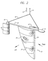
- FIG. 2 A second embodiment of a balloon trajectory control device is shown in FIG. 2.
- the main lift-generating element 31 is shown comprising an inverted sail 33, a mast 35, and a plurality of battens 37.
- the sail 33 and mast 35 are attached to a boom 39 having a front end and a back end.
- a counterweight 41 is attached to the front end of the boom.
- a rudder 43 and rudder actuator 45 are attached to back end of the boom.
- a control module 47 is mounted at a convenient location.
- the control module 47 includes a power source (not shown), if required, comprising a battery and a solar panel.
- a yoke 49 connects the boom to a tether 51.
- the upper end of the tether is attached to a winch 53 (not shown) mounted to an LTA system (e.g. a gondola of a balloon).
- the operation of the sail version of the trajectory control device is very similar to the operation of the wing version (FIG. 1).
- the use of a sail rather than a double-sided airfoil section is expected to have somewhat less efficient aerodynamic performance. However, this may be offset by the possible lower cost and mass. Indeed, it may be possible to use an existing sailboat sail rather than developing a custom design.
- Battens are thin ribs inserted into horizontal pockets sewn into sails to stiffen the sail material, to improve the aerodynamic shape, and to reduce luffing (i.e., flapping in the wind). They are often used on catamaran sailboats with their higher speed than regular sailboats. Although not required for the essential operation of the trajectory control device, it is expected that battens 37 will improve performance for the same reasons they are used in sailboat sails.
- the rudder is shown as a "flying" control surface meaning that the entire aerodynamic surface is rotated.
- a more conventional fixed fin and moveable rudder Either will serve the functions of stabilizing the weathercock motion of the main lifting surface and adjusting the angle of attack of the main lifting surface.
- control module 47 is shown with a more forward position indicating its ability to act in part as a counterweight.
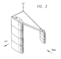
- FIG. 3 A third embodiment of a trajectory control device is shown in FIG. 3.
- the stabilizing surface is placed ahead of the main lifting surface.
- the small forward stabilizer is called a canard and the arrangement is referred to as a canard configuration.
- the operation of the canard configuration is very similar to the operation of the preferred embodiment with its conventional arrangement (stabilizer behind the main wing). Although the canard configuration looks unstable, the requirement that the center of gravity be ahead of the neutral point is identical to that of the conventional configuration.
- FIG. 4 A fourth embodiment of a trajectory control device is shown in FIG. 4.
- a biplane arrangement is used for the main lifting generating element. It is shown with a conventional arrangement with the stabilizer behind the main wings.
- the operation of the device with a biplane is identical to the operation with a single wing.
- An advantage of this configuration is structural: the box-like structure has inherently greater stiffness than for a monoplane. Similarly, the rudder could comprise multiple surfaces as well.
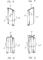
- FIG. 5 A fifth embodiment of a trajectory control device is shown in FIG. 5.
- the control device comprises a whirligig arrangement 61, whereby the device turns in the wind while generating a lift force.
- the whirligig arrangement 61 comprises a panel 63, at least one control flap 65, and at least one control flap actuator 67.
- the particular embodiment shown includes two flaps.
- the flaps 65 are hinged such that the angle between the flaps and the panel can be adjusted.
- a control module 69 is mounted at a convenient location.
- the control module includes a power source (not shown), if required, comprising a battery and a solar panel.
- a swivel 71 connects the whirligig arrangement 61 to a tether 73 which is connected to a winch 75 (not shown) attached to an LTA vehicle.
- ribs can be formed using lightweight tubes and covered with a thin fabric or polymeric film.
- the panels can be formed from a low-density essentially solid material such as Styrofoam.
- the whirligig arrangement 61 turns in the wind while generating a lift force, analogously to designs of various toys or kites.
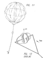
- a whirligig design from the prior art is illustrated in FIG 12, where the directions of wind and lift force are shown.
- This effect whereby there is a force perpendicular to the relative airflow is the Magnus effect, which accounts for curve balls in sports. This effect is discussed further on page 265 in "Mechanics of Fluids," third edition, by B.S. Massey, Van Nostrand, 1976, incorporated herein by reference.
- the whirligig design from the prior art comprises an elliptical styrofoam paddle with an S-shaped cross-section and a stiffening stick running through the long axis of the ellipse.
- the ends of the stick are connected by swivels to a yoke of string, which is fastened to the kite string.
- This toy operates with the stick horizontal and generates a vertical force due to the rotation in the wind. The upward force is sufficient to overcome the weight of the toy, which is stabilized by its central disk structure.
- the whirligig arrangement 61 of FIG. 5 operates on the same principle, although its axis is vertical rather than horizontal so the lift force is to the side rather than upward.
- the whirligig arrangement 61 is suspended on the long tether 73 from an LTA vehicle such that, relatively speaking, there is a predominantly horizontal flow of air.
- the control flaps 65 When the control flaps 65 are deployed antisymmetrically as shown in FIG. 5 the whirligig 61 rotates about an axis that is essentially vertical.
- FIG. 6 the direction of rotation is illustrated along with the directions of the wind W and the lift L. The whirligig will rotate in this direction regardless of the direction of the wind W.
- FIG. 7 shows the configuration with two control flaps deployed symmetrically and indicates the direction of the drag force D due to the wind W.
- FIG. 8 shows an alternative embodiment of a whirligig arrangement with three panels 63 and three control flaps 65.
- FIG. 9 shows an alternative embodiment of a whirligig arrangement using four panels 63 and flaps 65.
- FIG. 10 shows yet another embodiment of the whirligig arrangement in which a rotating cylinder is used as the lift-generating device. Control flaps 65 are also used to impart rotation to the cylinder.
- the body of a whirligig arrangement refers generally to a structure suitable for the mounting of control flaps, control flap actuators, and control modules in a whirligig arrangement (e.g., the panel 63 in FIG. 5 and the cylinder in FIG. 10).
- FIG. 11 illustrates the preferred embodiment of the trajectory control device shown in context suspended from a balloon and gondola.
- the relative scaling shown is somewhat arbitrary.
- the device can operate over a significant range of sizes.
- the length of the tether is likely to be longer than shown, but no restriction of the length should be inferred from the diagram.
- Any method of generating an aerodynamic force can be used to impart a force to the LTA vehicle.
- the particular examples of lift-generating devices illustrated here are intended to be exemplary, and not exclusive.
Landscapes
- Engineering & Computer Science (AREA)
- Mechanical Engineering (AREA)
- Aviation & Aerospace Engineering (AREA)
- Toys (AREA)
- Wind Motors (AREA)
- Control Of Position, Course, Altitude, Or Attitude Of Moving Bodies (AREA)
- Steering Control In Accordance With Driving Conditions (AREA)
- Percussion Or Vibration Massage (AREA)
Applications Claiming Priority (3)
| Application Number | Priority Date | Filing Date | Title |
|---|---|---|---|
| US106563 | 1987-10-07 | ||
| US09/106,563 US6402090B1 (en) | 1998-06-29 | 1998-06-29 | Balloon trajectory control system |
| PCT/US1999/014430 WO2000000387A2 (en) | 1998-06-29 | 1999-06-25 | Balloon trajectory control system |
Publications (3)
| Publication Number | Publication Date |
|---|---|
| EP1144247A2 EP1144247A2 (en) | 2001-10-17 |
| EP1144247A3 EP1144247A3 (en) | 2002-03-06 |
| EP1144247B1 true EP1144247B1 (en) | 2004-05-19 |
Family
ID=22312099
Family Applications (1)
| Application Number | Title | Priority Date | Filing Date |
|---|---|---|---|
| EP99931918A Expired - Lifetime EP1144247B1 (en) | 1998-06-29 | 1999-06-25 | Balloon trajectory control system |
Country Status (13)
| Country | Link |
|---|---|
| US (1) | US6402090B1 (enExample) |
| EP (1) | EP1144247B1 (enExample) |
| JP (1) | JP4505139B2 (enExample) |
| CN (1) | CN1168630C (enExample) |
| AT (1) | ATE267117T1 (enExample) |
| AU (1) | AU764203B2 (enExample) |
| BR (1) | BR9911653A (enExample) |
| CA (1) | CA2335954C (enExample) |
| DE (1) | DE69917487D1 (enExample) |
| HK (1) | HK1040224B (enExample) |
| NZ (1) | NZ509377A (enExample) |
| RU (1) | RU2238217C2 (enExample) |
| WO (1) | WO2000000387A2 (enExample) |
Families Citing this family (42)
| Publication number | Priority date | Publication date | Assignee | Title |
|---|---|---|---|---|
| US7356390B2 (en) | 1999-06-29 | 2008-04-08 | Space Data Corporation | Systems and applications of lighter-than-air (LTA) platforms |
| US9908608B2 (en) | 2001-04-18 | 2018-03-06 | Space Data Corporation | Systems and applications of lighter-than-air (LTA) platforms |
| US6925949B1 (en) * | 2002-12-31 | 2005-08-09 | Malcolm Phillips | Elevated sailing apparatus |
| GB0312353D0 (en) * | 2003-05-30 | 2003-07-02 | Qinetiq Ltd | Launching aerial vehicles |
| DE202004013841U1 (de) * | 2004-09-06 | 2006-01-19 | Skysails Gmbh & Co. Kg | Wasserfahrzeug mit einem drachenartigen Element |
| DE202004013840U1 (de) * | 2004-09-06 | 2006-01-19 | Skysails Gmbh & Co. Kg | Wasserfahrzeug mit einem drachenartigen Element |
| RU2342284C2 (ru) * | 2007-01-26 | 2008-12-27 | Сергей Юрьевич Козьяков | Комплекс для авиационных химических работ |
| US8091826B2 (en) * | 2007-04-24 | 2012-01-10 | Michael Todd Voorhees | Aerostatic buoyancy control system |
| US7994931B2 (en) * | 2008-08-01 | 2011-08-09 | Garmin Switzerland Gmbh | Graphical wind gauge |
| US8849571B1 (en) | 2012-12-26 | 2014-09-30 | Google Inc. | Methods and systems for determining fleet trajectories with phase-skipping to satisfy a sequence of coverage requirements |
| US9747568B1 (en) | 2012-12-26 | 2017-08-29 | X Development Llc | Methods and systems for determining when to decommission vehicles from a fleet of autonomous vehicles |
| US9424752B1 (en) | 2012-12-26 | 2016-08-23 | Google Inc. | Methods and systems for performing fleet planning based on coarse estimates of regions |
| US9195938B1 (en) | 2012-12-27 | 2015-11-24 | Google Inc. | Methods and systems for determining when to launch vehicles into a fleet of autonomous vehicles |
| US8948927B1 (en) | 2012-12-27 | 2015-02-03 | Google Inc. | Methods and systems for determining a distribution of balloons based on population densities |
| US8862403B1 (en) | 2012-12-28 | 2014-10-14 | Google Inc. | Methods and systems for determining altitudes for a vehicle to travel |
| US9014957B2 (en) | 2012-12-29 | 2015-04-21 | Google Inc. | Methods and systems for determining fleet trajectories to satisfy a sequence of coverage requirements |
| US9635706B1 (en) | 2013-01-02 | 2017-04-25 | X Development Llc | Method for determining fleet control policies to satisfy a sequence of coverage requirements |
| WO2014109917A1 (en) * | 2013-01-10 | 2014-07-17 | Leonid Goldstein | Airborne wind energy system |
| US8781727B1 (en) | 2013-01-15 | 2014-07-15 | Google Inc. | Methods and systems for performing flocking while executing a long-range fleet plan |
| US8874356B1 (en) | 2013-01-24 | 2014-10-28 | Google Inc. | Methods and systems for decomposing fleet planning optimizations via spatial partitions |
| US8880326B1 (en) | 2013-02-20 | 2014-11-04 | Google Inc. | Methods and systems for determining a cyclical fleet plan satisfying a recurring set of coverage requirements |
| CN103661915B (zh) * | 2013-11-18 | 2015-12-30 | 中国空间技术研究院 | 一种自然热和帆驱动的轨迹可控浮空器系统 |
| US9201426B1 (en) * | 2014-02-19 | 2015-12-01 | Google Inc. | Reverse iteration of planning data for system control |
| US9789960B2 (en) | 2015-01-14 | 2017-10-17 | Raymond Hoheisel | Payload orientation control and stabilization |
| US20160252908A1 (en) * | 2015-02-27 | 2016-09-01 | Ocean Lab, Llc | Reconfigurable drift measurement tool |
| RU2603870C1 (ru) * | 2015-08-12 | 2016-12-10 | Александр Поликарпович Лялин | Устройство управления траекторией полёта аэростата (уутпа) |
| US9665103B1 (en) | 2015-12-09 | 2017-05-30 | X Development Llc | Efficient aerostat navigation by moving between atmospheric layers |
| US10118696B1 (en) | 2016-03-31 | 2018-11-06 | Steven M. Hoffberg | Steerable rotating projectile |
| US10759535B2 (en) | 2016-06-14 | 2020-09-01 | Raymond Hoheisel | Airborne launch of inflatable devices |
| CN107867386B (zh) * | 2016-09-28 | 2022-06-03 | 深圳光启空间技术有限公司 | 浮空器的降落控制方法 |
| US10437259B2 (en) * | 2017-07-28 | 2019-10-08 | Loon Llc | Systems and methods for controlling aerial vehicles |
| US10809718B2 (en) | 2017-07-28 | 2020-10-20 | Loon Llc | Systems and methods for controlling aerial vehicles |
| US10437260B2 (en) | 2017-07-28 | 2019-10-08 | Loon Llc | Systems and methods for controlling aerial vehicles |
| US10558219B2 (en) | 2017-09-21 | 2020-02-11 | Loon Llc | Systems and methods for controlling an aerial vehicle using lateral propulsion and vertical movement |
| US10780969B2 (en) * | 2017-12-21 | 2020-09-22 | Loon Llc | Propulsion system for a buoyant aerial vehicle |
| US11712637B1 (en) | 2018-03-23 | 2023-08-01 | Steven M. Hoffberg | Steerable disk or ball |
| RU2712468C1 (ru) * | 2019-03-22 | 2020-01-29 | ФЕДЕРАЛЬНОЕ ГОСУДАРСТВЕННОЕ КАЗЕННОЕ ВОЕННОЕ ОБРАЗОВАТЕЛЬНОЕ УЧРЕЖДЕНИЕ ВЫСШЕГО ОБРАЗОВАНИЯ "Военная академия Ракетных войск стратегического назначения имени Петра Великого" МИНИСТЕРСТВА ОБОРОНЫ РОССИЙСКОЙ ФЕДЕРАЦИИ | Система обнаружения воздушных и наземных целей |
| US11220320B2 (en) | 2019-07-17 | 2022-01-11 | Aerostar International, Inc. | Lateral propulsion systems and architectures for high altitude balloons |
| US11679854B2 (en) * | 2020-12-28 | 2023-06-20 | Urban Sky Theory Inc. | Launch system for lighter-than-air-balloons |
| US11834145B2 (en) * | 2021-04-15 | 2023-12-05 | Samuel A Johnson | Camera stabilization in aerial photography and videography |
| US12466586B2 (en) * | 2023-07-21 | 2025-11-11 | Windborne Systems Inc. | System and method for generating aerodynamic lift from wind shear at a system |
| CN116719227B (zh) * | 2023-08-11 | 2023-10-24 | 北京瞭望神州科技有限公司 | 一种应用于耕地智保场景的保护方法及保护系统 |
Family Cites Families (15)
| Publication number | Priority date | Publication date | Assignee | Title |
|---|---|---|---|---|
| US361855A (en) * | 1887-04-26 | Tereitoey | ||
| US1546803A (en) * | 1924-12-15 | 1925-07-21 | Oscar H Sternberg | Buoying device for aeroplanes |
| US1652997A (en) * | 1926-12-21 | 1927-12-20 | Azarraga Luis | Aerial advertising device |
| US1816898A (en) * | 1928-12-29 | 1931-08-04 | Few Sonia Fontaine | Airplane |
| US1839005A (en) | 1930-11-12 | 1931-12-29 | Jr Frederick Wander | Rotary wing for aeroplanes |
| US3135482A (en) * | 1962-12-26 | 1964-06-02 | Ryan Aeronautical Co | Flexible wing stol assist system for aircraft |
| US3614024A (en) * | 1970-04-06 | 1971-10-19 | Rohr Corp | Combined water surface and air craft |
| US4375280A (en) * | 1974-01-30 | 1983-03-01 | Nicolaides John D | Free wing flyer |
| US4050653A (en) * | 1976-03-15 | 1977-09-27 | Bernard Sayers | Balloon |
| FR2452423A1 (fr) | 1979-03-27 | 1980-10-24 | Costes Didier | Procede de navigation pour un ballon au-dessus de l'eau |
| FR2588821A1 (fr) | 1985-10-21 | 1987-04-24 | Costes Didier | Planeur aquatique associable a un ballon dirigeable |
| ZA88788B (en) * | 1987-08-03 | 1988-10-26 | Vincent Renecle Keith | Highly manoeuvrable control line kite |
| FR2668751A1 (fr) | 1990-11-02 | 1992-05-07 | Scene Communication Nouvelle | Systeme pour maintenir un cerf-volant et les structures pouvant s'y rattacher, dans les airs. |
| GB2266285B (en) * | 1992-04-25 | 1995-11-29 | British Aerospace | Towed aerodynamic bodies |
| RU2111149C1 (ru) * | 1995-08-16 | 1998-05-20 | Быков Юрий Алексеевич | Способ осуществления полета в воздухе физического тела, связанного с аэродинамической поверхностью |
-
1998
- 1998-06-29 US US09/106,563 patent/US6402090B1/en not_active Expired - Lifetime
-
1999
- 1999-06-25 RU RU2001102511A patent/RU2238217C2/ru not_active IP Right Cessation
- 1999-06-25 AU AU48329/99A patent/AU764203B2/en not_active Ceased
- 1999-06-25 CN CNB998081280A patent/CN1168630C/zh not_active Expired - Fee Related
- 1999-06-25 HK HK02102018.2A patent/HK1040224B/zh not_active IP Right Cessation
- 1999-06-25 DE DE69917487T patent/DE69917487D1/de not_active Expired - Fee Related
- 1999-06-25 BR BR9911653-7A patent/BR9911653A/pt not_active IP Right Cessation
- 1999-06-25 CA CA002335954A patent/CA2335954C/en not_active Expired - Fee Related
- 1999-06-25 NZ NZ509377A patent/NZ509377A/en not_active IP Right Cessation
- 1999-06-25 WO PCT/US1999/014430 patent/WO2000000387A2/en not_active Ceased
- 1999-06-25 JP JP2000556957A patent/JP4505139B2/ja not_active Expired - Fee Related
- 1999-06-25 AT AT99931918T patent/ATE267117T1/de not_active IP Right Cessation
- 1999-06-25 EP EP99931918A patent/EP1144247B1/en not_active Expired - Lifetime
Also Published As
| Publication number | Publication date |
|---|---|
| AU4832999A (en) | 2000-01-17 |
| ATE267117T1 (de) | 2004-06-15 |
| JP4505139B2 (ja) | 2010-07-21 |
| WO2000000387A3 (en) | 2001-12-13 |
| US6402090B1 (en) | 2002-06-11 |
| BR9911653A (pt) | 2001-10-09 |
| CN1322176A (zh) | 2001-11-14 |
| CN1168630C (zh) | 2004-09-29 |
| EP1144247A2 (en) | 2001-10-17 |
| CA2335954A1 (en) | 2000-01-06 |
| WO2000000387A2 (en) | 2000-01-06 |
| NZ509377A (en) | 2003-08-29 |
| CA2335954C (en) | 2007-04-24 |
| EP1144247A3 (en) | 2002-03-06 |
| AU764203B2 (en) | 2003-08-14 |
| HK1040224B (zh) | 2005-05-20 |
| JP2002519236A (ja) | 2002-07-02 |
| DE69917487D1 (de) | 2004-06-24 |
| RU2238217C2 (ru) | 2004-10-20 |
| HK1040224A1 (en) | 2002-05-31 |
Similar Documents
| Publication | Publication Date | Title |
|---|---|---|
| EP1144247B1 (en) | Balloon trajectory control system | |
| EP3287358B1 (en) | Tethered unmanned aerial vehicle | |
| US7530527B2 (en) | Method and device for launching aerial vehicles | |
| US6609680B2 (en) | High altitude airships | |
| EP1551706B1 (en) | Dual hull airship controlled by thrust vectoring | |
| US8061647B1 (en) | High altitude two balloon airship | |
| US11305863B1 (en) | Hybrid lighter-than-air vehicle | |
| US6925949B1 (en) | Elevated sailing apparatus | |
| US20160229518A1 (en) | Hybrid lighter-than-air vehicle | |
| Aaron et al. | Balloon trajectory control | |
| JP5811384B1 (ja) | 空中浮揚装置及びその空中航法 | |
| CN115892435B (zh) | 一种基于风帆助航的双浮空器系统及其区域驻留控制策略 | |
| Hecks | Pressure airships: a review | |
| JP2022150020A (ja) | 無人航空機およびその制御方法 | |
| JP2020147266A (ja) | 可変翼カイト | |
| JPH0328100A (ja) | 軽量浮揚体 |
Legal Events
| Date | Code | Title | Description |
|---|---|---|---|
| PUAI | Public reference made under article 153(3) epc to a published international application that has entered the european phase |
Free format text: ORIGINAL CODE: 0009012 |
|
| 17P | Request for examination filed |
Effective date: 20010117 |
|
| AK | Designated contracting states |
Kind code of ref document: A2 Designated state(s): AT BE CH CY DE DK ES FI FR GB GR IE IT LI LU MC NL PT SE |
|
| XX | Miscellaneous (additional remarks) |
Free format text: DERZEIT SIND DIE WIPO-PUBLIKATIONSDATEN A3 NICHT VERFUEGBAR. |
|
| PUAK | Availability of information related to the publication of the international search report |
Free format text: ORIGINAL CODE: 0009015 |
|
| AK | Designated contracting states |
Kind code of ref document: A3 Designated state(s): AT BE CH CY DE DK ES FI FR GB GR IE IT LI LU MC NL PT SE |
|
| RAP1 | Party data changed (applicant data changed or rights of an application transferred) |
Owner name: GLOBAL AEROSPACE CORPORATION |
|
| 17Q | First examination report despatched |
Effective date: 20021203 |
|
| GRAP | Despatch of communication of intention to grant a patent |
Free format text: ORIGINAL CODE: EPIDOSNIGR1 |
|
| GRAS | Grant fee paid |
Free format text: ORIGINAL CODE: EPIDOSNIGR3 |
|
| GRAA | (expected) grant |
Free format text: ORIGINAL CODE: 0009210 |
|
| AK | Designated contracting states |
Kind code of ref document: B1 Designated state(s): AT BE CH CY DE DK ES FI FR GB GR IE IT LI LU MC NL PT SE |
|
| PG25 | Lapsed in a contracting state [announced via postgrant information from national office to epo] |
Ref country code: NL Free format text: LAPSE BECAUSE OF FAILURE TO SUBMIT A TRANSLATION OF THE DESCRIPTION OR TO PAY THE FEE WITHIN THE PRESCRIBED TIME-LIMIT Effective date: 20040519 Ref country code: LI Free format text: LAPSE BECAUSE OF FAILURE TO SUBMIT A TRANSLATION OF THE DESCRIPTION OR TO PAY THE FEE WITHIN THE PRESCRIBED TIME-LIMIT Effective date: 20040519 Ref country code: FI Free format text: LAPSE BECAUSE OF FAILURE TO SUBMIT A TRANSLATION OF THE DESCRIPTION OR TO PAY THE FEE WITHIN THE PRESCRIBED TIME-LIMIT Effective date: 20040519 Ref country code: CY Free format text: LAPSE BECAUSE OF FAILURE TO SUBMIT A TRANSLATION OF THE DESCRIPTION OR TO PAY THE FEE WITHIN THE PRESCRIBED TIME-LIMIT Effective date: 20040519 Ref country code: CH Free format text: LAPSE BECAUSE OF FAILURE TO SUBMIT A TRANSLATION OF THE DESCRIPTION OR TO PAY THE FEE WITHIN THE PRESCRIBED TIME-LIMIT Effective date: 20040519 Ref country code: BE Free format text: LAPSE BECAUSE OF FAILURE TO SUBMIT A TRANSLATION OF THE DESCRIPTION OR TO PAY THE FEE WITHIN THE PRESCRIBED TIME-LIMIT Effective date: 20040519 Ref country code: AT Free format text: LAPSE BECAUSE OF FAILURE TO SUBMIT A TRANSLATION OF THE DESCRIPTION OR TO PAY THE FEE WITHIN THE PRESCRIBED TIME-LIMIT Effective date: 20040519 |
|
| REG | Reference to a national code |
Ref country code: GB Ref legal event code: FG4D |
|
| XX | Miscellaneous (additional remarks) |
Free format text: DERZEIT SIND DIE WIPO-PUBLIKATIONSDATEN A3 NICHT VERFUEGBAR. |
|
| REG | Reference to a national code |
Ref country code: CH Ref legal event code: EP |
|
| REG | Reference to a national code |
Ref country code: IE Ref legal event code: FG4D |
|
| REF | Corresponds to: |
Ref document number: 69917487 Country of ref document: DE Date of ref document: 20040624 Kind code of ref document: P |
|
| PG25 | Lapsed in a contracting state [announced via postgrant information from national office to epo] |
Ref country code: LU Free format text: LAPSE BECAUSE OF NON-PAYMENT OF DUE FEES Effective date: 20040625 Ref country code: IE Free format text: LAPSE BECAUSE OF NON-PAYMENT OF DUE FEES Effective date: 20040625 |
|
| PG25 | Lapsed in a contracting state [announced via postgrant information from national office to epo] |
Ref country code: MC Free format text: LAPSE BECAUSE OF NON-PAYMENT OF DUE FEES Effective date: 20040630 |
|
| PG25 | Lapsed in a contracting state [announced via postgrant information from national office to epo] |
Ref country code: GR Free format text: LAPSE BECAUSE OF FAILURE TO SUBMIT A TRANSLATION OF THE DESCRIPTION OR TO PAY THE FEE WITHIN THE PRESCRIBED TIME-LIMIT Effective date: 20040819 Ref country code: DK Free format text: LAPSE BECAUSE OF FAILURE TO SUBMIT A TRANSLATION OF THE DESCRIPTION OR TO PAY THE FEE WITHIN THE PRESCRIBED TIME-LIMIT Effective date: 20040819 |
|
| PG25 | Lapsed in a contracting state [announced via postgrant information from national office to epo] |
Ref country code: ES Free format text: LAPSE BECAUSE OF FAILURE TO SUBMIT A TRANSLATION OF THE DESCRIPTION OR TO PAY THE FEE WITHIN THE PRESCRIBED TIME-LIMIT Effective date: 20040830 |
|
| REG | Reference to a national code |
Ref country code: SE Ref legal event code: TRGR |
|
| NLV1 | Nl: lapsed or annulled due to failure to fulfill the requirements of art. 29p and 29m of the patents act | ||
| REG | Reference to a national code |
Ref country code: CH Ref legal event code: PL |
|
| PG25 | Lapsed in a contracting state [announced via postgrant information from national office to epo] |
Ref country code: DE Free format text: LAPSE BECAUSE OF NON-PAYMENT OF DUE FEES Effective date: 20050101 |
|
| ET | Fr: translation filed | ||
| EUG | Se: european patent has lapsed | ||
| PLBE | No opposition filed within time limit |
Free format text: ORIGINAL CODE: 0009261 |
|
| STAA | Information on the status of an ep patent application or granted ep patent |
Free format text: STATUS: NO OPPOSITION FILED WITHIN TIME LIMIT |
|
| REG | Reference to a national code |
Ref country code: IE Ref legal event code: MM4A |
|
| 26N | No opposition filed |
Effective date: 20050222 |
|
| REG | Reference to a national code |
Ref country code: FR Ref legal event code: ST |
|
| PG25 | Lapsed in a contracting state [announced via postgrant information from national office to epo] |
Ref country code: IT Free format text: LAPSE BECAUSE OF NON-PAYMENT OF DUE FEES Effective date: 20050625 |
|
| REG | Reference to a national code |
Ref country code: FR Ref legal event code: RN |
|
| REG | Reference to a national code |
Ref country code: FR Ref legal event code: FC |
|
| PG25 | Lapsed in a contracting state [announced via postgrant information from national office to epo] |
Ref country code: PT Free format text: LAPSE BECAUSE OF NON-PAYMENT OF DUE FEES Effective date: 20041019 |
|
| PGRI | Patent reinstated in contracting state [announced from national office to epo] |
Ref country code: IT Effective date: 20080301 |
|
| PGFP | Annual fee paid to national office [announced via postgrant information from national office to epo] |
Ref country code: SE Payment date: 20100604 Year of fee payment: 12 |
|
| PG25 | Lapsed in a contracting state [announced via postgrant information from national office to epo] |
Ref country code: SE Free format text: LAPSE BECAUSE OF FAILURE TO SUBMIT A TRANSLATION OF THE DESCRIPTION OR TO PAY THE FEE WITHIN THE PRESCRIBED TIME-LIMIT Effective date: 20040519 |
|
| REG | Reference to a national code |
Ref country code: FR Ref legal event code: PLFP Year of fee payment: 18 |
|
| REG | Reference to a national code |
Ref country code: FR Ref legal event code: PLFP Year of fee payment: 19 |
|
| PGFP | Annual fee paid to national office [announced via postgrant information from national office to epo] |
Ref country code: FR Payment date: 20170322 Year of fee payment: 19 |
|
| PGFP | Annual fee paid to national office [announced via postgrant information from national office to epo] |
Ref country code: IT Payment date: 20170331 Year of fee payment: 19 |
|
| PGFP | Annual fee paid to national office [announced via postgrant information from national office to epo] |
Ref country code: GB Payment date: 20170426 Year of fee payment: 19 |
|
| GBPC | Gb: european patent ceased through non-payment of renewal fee |
Effective date: 20180625 |
|
| PG25 | Lapsed in a contracting state [announced via postgrant information from national office to epo] |
Ref country code: IT Free format text: LAPSE BECAUSE OF NON-PAYMENT OF DUE FEES Effective date: 20180625 Ref country code: FR Free format text: LAPSE BECAUSE OF NON-PAYMENT OF DUE FEES Effective date: 20180630 Ref country code: GB Free format text: LAPSE BECAUSE OF NON-PAYMENT OF DUE FEES Effective date: 20180625 |