EP3287358B1 - Tethered unmanned aerial vehicle - Google Patents
Tethered unmanned aerial vehicle Download PDFInfo
- Publication number
- EP3287358B1 EP3287358B1 EP17000982.3A EP17000982A EP3287358B1 EP 3287358 B1 EP3287358 B1 EP 3287358B1 EP 17000982 A EP17000982 A EP 17000982A EP 3287358 B1 EP3287358 B1 EP 3287358B1
- Authority
- EP
- European Patent Office
- Prior art keywords
- tuav
- wing
- air
- tether
- wind
- Prior art date
- Legal status (The legal status is an assumption and is not a legal conclusion. Google has not performed a legal analysis and makes no representation as to the accuracy of the status listed.)
- Active
Links
- RZVHIXYEVGDQDX-UHFFFAOYSA-N 9,10-anthraquinone Chemical compound C1=CC=C2C(=O)C3=CC=CC=C3C(=O)C2=C1 RZVHIXYEVGDQDX-UHFFFAOYSA-N 0.000 claims description 21
- XLYOFNOQVPJJNP-UHFFFAOYSA-N water Substances O XLYOFNOQVPJJNP-UHFFFAOYSA-N 0.000 claims description 16
- 230000004044 response Effects 0.000 claims description 15
- 238000000034 method Methods 0.000 claims description 13
- 230000033001 locomotion Effects 0.000 claims description 5
- 230000007935 neutral effect Effects 0.000 claims description 4
- 238000001816 cooling Methods 0.000 claims description 3
- 239000003570 air Substances 0.000 description 37
- 239000007789 gas Substances 0.000 description 36
- 238000013461 design Methods 0.000 description 14
- 238000010248 power generation Methods 0.000 description 13
- 238000004891 communication Methods 0.000 description 7
- 230000006870 function Effects 0.000 description 7
- UFHFLCQGNIYNRP-UHFFFAOYSA-N Hydrogen Chemical compound [H][H] UFHFLCQGNIYNRP-UHFFFAOYSA-N 0.000 description 6
- 230000003466 anti-cipated effect Effects 0.000 description 6
- 239000001257 hydrogen Substances 0.000 description 6
- 229910052739 hydrogen Inorganic materials 0.000 description 6
- 238000006243 chemical reaction Methods 0.000 description 4
- 239000002131 composite material Substances 0.000 description 4
- 230000001276 controlling effect Effects 0.000 description 4
- 238000010586 diagram Methods 0.000 description 4
- 239000000463 material Substances 0.000 description 4
- -1 aluminum alloy) Chemical class 0.000 description 3
- 230000008901 benefit Effects 0.000 description 3
- 230000005611 electricity Effects 0.000 description 3
- 239000004744 fabric Substances 0.000 description 3
- 230000010006 flight Effects 0.000 description 3
- 239000000446 fuel Substances 0.000 description 3
- 238000007726 management method Methods 0.000 description 3
- 238000012544 monitoring process Methods 0.000 description 3
- 239000011257 shell material Substances 0.000 description 3
- 229910000838 Al alloy Inorganic materials 0.000 description 2
- 229910045601 alloy Inorganic materials 0.000 description 2
- 239000000956 alloy Substances 0.000 description 2
- QVGXLLKOCUKJST-UHFFFAOYSA-N atomic oxygen Chemical compound [O] QVGXLLKOCUKJST-UHFFFAOYSA-N 0.000 description 2
- 238000013500 data storage Methods 0.000 description 2
- 239000001307 helium Substances 0.000 description 2
- 229910052734 helium Inorganic materials 0.000 description 2
- SWQJXJOGLNCZEY-UHFFFAOYSA-N helium atom Chemical compound [He] SWQJXJOGLNCZEY-UHFFFAOYSA-N 0.000 description 2
- 229910052751 metal Inorganic materials 0.000 description 2
- 239000002184 metal Substances 0.000 description 2
- 150000002739 metals Chemical class 0.000 description 2
- 239000001301 oxygen Substances 0.000 description 2
- 229910052760 oxygen Inorganic materials 0.000 description 2
- 229920000139 polyethylene terephthalate Polymers 0.000 description 2
- 239000005020 polyethylene terephthalate Substances 0.000 description 2
- 238000011084 recovery Methods 0.000 description 2
- 230000011664 signaling Effects 0.000 description 2
- 230000003068 static effect Effects 0.000 description 2
- 239000002023 wood Substances 0.000 description 2
- 239000004642 Polyimide Substances 0.000 description 1
- 239000012080 ambient air Substances 0.000 description 1
- 238000013459 approach Methods 0.000 description 1
- 230000015572 biosynthetic process Effects 0.000 description 1
- 238000007664 blowing Methods 0.000 description 1
- 230000001413 cellular effect Effects 0.000 description 1
- 238000002485 combustion reaction Methods 0.000 description 1
- 238000009833 condensation Methods 0.000 description 1
- 230000005494 condensation Effects 0.000 description 1
- 230000000694 effects Effects 0.000 description 1
- 238000005868 electrolysis reaction Methods 0.000 description 1
- 239000000284 extract Substances 0.000 description 1
- 238000007667 floating Methods 0.000 description 1
- 230000005484 gravity Effects 0.000 description 1
- 238000003384 imaging method Methods 0.000 description 1
- 239000007788 liquid Substances 0.000 description 1
- 238000012423 maintenance Methods 0.000 description 1
- 239000012528 membrane Substances 0.000 description 1
- 230000003287 optical effect Effects 0.000 description 1
- 239000013307 optical fiber Substances 0.000 description 1
- 239000002985 plastic film Substances 0.000 description 1
- 229920000728 polyester Polymers 0.000 description 1
- 229920001721 polyimide Polymers 0.000 description 1
- 238000012545 processing Methods 0.000 description 1
- 230000001105 regulatory effect Effects 0.000 description 1
- 230000001953 sensory effect Effects 0.000 description 1
- 150000003384 small molecules Chemical class 0.000 description 1
- 239000007787 solid Substances 0.000 description 1
- 230000000087 stabilizing effect Effects 0.000 description 1
- 239000010409 thin film Substances 0.000 description 1
Images


Classifications
-
- B—PERFORMING OPERATIONS; TRANSPORTING
- B64—AIRCRAFT; AVIATION; COSMONAUTICS
- B64C—AEROPLANES; HELICOPTERS
- B64C39/00—Aircraft not otherwise provided for
- B64C39/02—Aircraft not otherwise provided for characterised by special use
- B64C39/022—Tethered aircraft
-
- B—PERFORMING OPERATIONS; TRANSPORTING
- B64—AIRCRAFT; AVIATION; COSMONAUTICS
- B64B—LIGHTER-THAN AIR AIRCRAFT
- B64B1/00—Lighter-than-air aircraft
- B64B1/06—Rigid airships; Semi-rigid airships
-
- B—PERFORMING OPERATIONS; TRANSPORTING
- B64—AIRCRAFT; AVIATION; COSMONAUTICS
- B64B—LIGHTER-THAN AIR AIRCRAFT
- B64B1/00—Lighter-than-air aircraft
- B64B1/06—Rigid airships; Semi-rigid airships
- B64B1/12—Movable control surfaces
-
- B—PERFORMING OPERATIONS; TRANSPORTING
- B64—AIRCRAFT; AVIATION; COSMONAUTICS
- B64B—LIGHTER-THAN AIR AIRCRAFT
- B64B1/00—Lighter-than-air aircraft
- B64B1/06—Rigid airships; Semi-rigid airships
- B64B1/20—Rigid airships; Semi-rigid airships provided with wings or stabilising surfaces
-
- B—PERFORMING OPERATIONS; TRANSPORTING
- B64—AIRCRAFT; AVIATION; COSMONAUTICS
- B64B—LIGHTER-THAN AIR AIRCRAFT
- B64B1/00—Lighter-than-air aircraft
- B64B1/40—Balloons
- B64B1/50—Captive balloons
-
- B—PERFORMING OPERATIONS; TRANSPORTING
- B64—AIRCRAFT; AVIATION; COSMONAUTICS
- B64B—LIGHTER-THAN AIR AIRCRAFT
- B64B1/00—Lighter-than-air aircraft
- B64B1/58—Arrangements or construction of gas-bags; Filling arrangements
-
- B—PERFORMING OPERATIONS; TRANSPORTING
- B64—AIRCRAFT; AVIATION; COSMONAUTICS
- B64B—LIGHTER-THAN AIR AIRCRAFT
- B64B1/00—Lighter-than-air aircraft
- B64B1/58—Arrangements or construction of gas-bags; Filling arrangements
- B64B1/62—Controlling gas pressure, heating, cooling, or discharging gas
-
- B—PERFORMING OPERATIONS; TRANSPORTING
- B64—AIRCRAFT; AVIATION; COSMONAUTICS
- B64C—AEROPLANES; HELICOPTERS
- B64C39/00—Aircraft not otherwise provided for
- B64C39/02—Aircraft not otherwise provided for characterised by special use
- B64C39/024—Aircraft not otherwise provided for characterised by special use of the remote controlled vehicle type, i.e. RPV
-
- B—PERFORMING OPERATIONS; TRANSPORTING
- B64—AIRCRAFT; AVIATION; COSMONAUTICS
- B64U—UNMANNED AERIAL VEHICLES [UAV]; EQUIPMENT THEREFOR
- B64U10/00—Type of UAV
- B64U10/60—Tethered aircraft
-
- B—PERFORMING OPERATIONS; TRANSPORTING
- B64—AIRCRAFT; AVIATION; COSMONAUTICS
- B64U—UNMANNED AERIAL VEHICLES [UAV]; EQUIPMENT THEREFOR
- B64U30/00—Means for producing lift; Empennages; Arrangements thereof
- B64U30/10—Wings
-
- B—PERFORMING OPERATIONS; TRANSPORTING
- B64—AIRCRAFT; AVIATION; COSMONAUTICS
- B64U—UNMANNED AERIAL VEHICLES [UAV]; EQUIPMENT THEREFOR
- B64U50/00—Propulsion; Power supply
- B64U50/30—Supply or distribution of electrical power
- B64U50/34—In-flight charging
- B64U50/36—In-flight charging by wind turbines, e.g. ram air turbines [RAT]
-
- F—MECHANICAL ENGINEERING; LIGHTING; HEATING; WEAPONS; BLASTING
- F03—MACHINES OR ENGINES FOR LIQUIDS; WIND, SPRING, OR WEIGHT MOTORS; PRODUCING MECHANICAL POWER OR A REACTIVE PROPULSIVE THRUST, NOT OTHERWISE PROVIDED FOR
- F03B—MACHINES OR ENGINES FOR LIQUIDS
- F03B17/00—Other machines or engines
- F03B17/06—Other machines or engines using liquid flow with predominantly kinetic energy conversion, e.g. of swinging-flap type, "run-of-river", "ultra-low head"
-
- F—MECHANICAL ENGINEERING; LIGHTING; HEATING; WEAPONS; BLASTING
- F03—MACHINES OR ENGINES FOR LIQUIDS; WIND, SPRING, OR WEIGHT MOTORS; PRODUCING MECHANICAL POWER OR A REACTIVE PROPULSIVE THRUST, NOT OTHERWISE PROVIDED FOR
- F03D—WIND MOTORS
- F03D1/00—Wind motors with rotation axis substantially parallel to the air flow entering the rotor
- F03D1/04—Wind motors with rotation axis substantially parallel to the air flow entering the rotor having stationary wind-guiding means, e.g. with shrouds or channels
-
- F—MECHANICAL ENGINEERING; LIGHTING; HEATING; WEAPONS; BLASTING
- F03—MACHINES OR ENGINES FOR LIQUIDS; WIND, SPRING, OR WEIGHT MOTORS; PRODUCING MECHANICAL POWER OR A REACTIVE PROPULSIVE THRUST, NOT OTHERWISE PROVIDED FOR
- F03D—WIND MOTORS
- F03D13/00—Assembly, mounting or commissioning of wind motors; Arrangements specially adapted for transporting wind motor components
- F03D13/20—Arrangements for mounting or supporting wind motors; Masts or towers for wind motors
-
- F—MECHANICAL ENGINEERING; LIGHTING; HEATING; WEAPONS; BLASTING
- F03—MACHINES OR ENGINES FOR LIQUIDS; WIND, SPRING, OR WEIGHT MOTORS; PRODUCING MECHANICAL POWER OR A REACTIVE PROPULSIVE THRUST, NOT OTHERWISE PROVIDED FOR
- F03D—WIND MOTORS
- F03D9/00—Adaptations of wind motors for special use; Combinations of wind motors with apparatus driven thereby; Wind motors specially adapted for installation in particular locations
- F03D9/30—Wind motors specially adapted for installation in particular locations
- F03D9/32—Wind motors specially adapted for installation in particular locations on moving objects, e.g. vehicles
-
- G—PHYSICS
- G05—CONTROLLING; REGULATING
- G05D—SYSTEMS FOR CONTROLLING OR REGULATING NON-ELECTRIC VARIABLES
- G05D1/00—Control of position, course or altitude of land, water, air, or space vehicles, e.g. automatic pilot
- G05D1/08—Control of attitude, i.e. control of roll, pitch, or yaw
- G05D1/0808—Control of attitude, i.e. control of roll, pitch, or yaw specially adapted for aircraft
- G05D1/0866—Control of attitude, i.e. control of roll, pitch, or yaw specially adapted for aircraft specially adapted to captive aircraft
-
- B—PERFORMING OPERATIONS; TRANSPORTING
- B63—SHIPS OR OTHER WATERBORNE VESSELS; RELATED EQUIPMENT
- B63B—SHIPS OR OTHER WATERBORNE VESSELS; EQUIPMENT FOR SHIPPING
- B63B35/00—Vessels or similar floating structures specially adapted for specific purposes and not otherwise provided for
- B63B2035/006—Unmanned surface vessels, e.g. remotely controlled
-
- B—PERFORMING OPERATIONS; TRANSPORTING
- B63—SHIPS OR OTHER WATERBORNE VESSELS; RELATED EQUIPMENT
- B63G—OFFENSIVE OR DEFENSIVE ARRANGEMENTS ON VESSELS; MINE-LAYING; MINE-SWEEPING; SUBMARINES; AIRCRAFT CARRIERS
- B63G8/00—Underwater vessels, e.g. submarines; Equipment specially adapted therefor
- B63G8/001—Underwater vessels adapted for special purposes, e.g. unmanned underwater vessels; Equipment specially adapted therefor, e.g. docking stations
- B63G2008/002—Underwater vessels adapted for special purposes, e.g. unmanned underwater vessels; Equipment specially adapted therefor, e.g. docking stations unmanned
-
- B—PERFORMING OPERATIONS; TRANSPORTING
- B64—AIRCRAFT; AVIATION; COSMONAUTICS
- B64C—AEROPLANES; HELICOPTERS
- B64C9/00—Adjustable control surfaces or members, e.g. rudders
- B64C2009/005—Ailerons
-
- B—PERFORMING OPERATIONS; TRANSPORTING
- B64—AIRCRAFT; AVIATION; COSMONAUTICS
- B64U—UNMANNED AERIAL VEHICLES [UAV]; EQUIPMENT THEREFOR
- B64U10/00—Type of UAV
- B64U10/25—Fixed-wing aircraft
-
- B—PERFORMING OPERATIONS; TRANSPORTING
- B64—AIRCRAFT; AVIATION; COSMONAUTICS
- B64U—UNMANNED AERIAL VEHICLES [UAV]; EQUIPMENT THEREFOR
- B64U2201/00—UAVs characterised by their flight controls
- B64U2201/20—Remote controls
- B64U2201/202—Remote controls using tethers for connecting to ground station
-
- B—PERFORMING OPERATIONS; TRANSPORTING
- B64—AIRCRAFT; AVIATION; COSMONAUTICS
- B64U—UNMANNED AERIAL VEHICLES [UAV]; EQUIPMENT THEREFOR
- B64U50/00—Propulsion; Power supply
- B64U50/30—Supply or distribution of electrical power
- B64U50/34—In-flight charging
-
- B—PERFORMING OPERATIONS; TRANSPORTING
- B64—AIRCRAFT; AVIATION; COSMONAUTICS
- B64U—UNMANNED AERIAL VEHICLES [UAV]; EQUIPMENT THEREFOR
- B64U70/00—Launching, take-off or landing arrangements
- B64U70/30—Launching, take-off or landing arrangements for capturing UAVs in flight by ground or sea-based arresting gear, e.g. by a cable or a net
-
- F—MECHANICAL ENGINEERING; LIGHTING; HEATING; WEAPONS; BLASTING
- F03—MACHINES OR ENGINES FOR LIQUIDS; WIND, SPRING, OR WEIGHT MOTORS; PRODUCING MECHANICAL POWER OR A REACTIVE PROPULSIVE THRUST, NOT OTHERWISE PROVIDED FOR
- F03D—WIND MOTORS
- F03D5/00—Other wind motors
-
- F—MECHANICAL ENGINEERING; LIGHTING; HEATING; WEAPONS; BLASTING
- F05—INDEXING SCHEMES RELATING TO ENGINES OR PUMPS IN VARIOUS SUBCLASSES OF CLASSES F01-F04
- F05B—INDEXING SCHEME RELATING TO WIND, SPRING, WEIGHT, INERTIA OR LIKE MOTORS, TO MACHINES OR ENGINES FOR LIQUIDS COVERED BY SUBCLASSES F03B, F03D AND F03G
- F05B2220/00—Application
- F05B2220/70—Application in combination with
- F05B2220/706—Application in combination with an electrical generator
-
- F—MECHANICAL ENGINEERING; LIGHTING; HEATING; WEAPONS; BLASTING
- F05—INDEXING SCHEMES RELATING TO ENGINES OR PUMPS IN VARIOUS SUBCLASSES OF CLASSES F01-F04
- F05B—INDEXING SCHEME RELATING TO WIND, SPRING, WEIGHT, INERTIA OR LIKE MOTORS, TO MACHINES OR ENGINES FOR LIQUIDS COVERED BY SUBCLASSES F03B, F03D AND F03G
- F05B2240/00—Components
- F05B2240/10—Stators
- F05B2240/12—Fluid guiding means, e.g. vanes
- F05B2240/123—Nozzles
-
- F—MECHANICAL ENGINEERING; LIGHTING; HEATING; WEAPONS; BLASTING
- F05—INDEXING SCHEMES RELATING TO ENGINES OR PUMPS IN VARIOUS SUBCLASSES OF CLASSES F01-F04
- F05B—INDEXING SCHEME RELATING TO WIND, SPRING, WEIGHT, INERTIA OR LIKE MOTORS, TO MACHINES OR ENGINES FOR LIQUIDS COVERED BY SUBCLASSES F03B, F03D AND F03G
- F05B2240/00—Components
- F05B2240/20—Rotors
- F05B2240/21—Rotors for wind turbines
-
- F—MECHANICAL ENGINEERING; LIGHTING; HEATING; WEAPONS; BLASTING
- F05—INDEXING SCHEMES RELATING TO ENGINES OR PUMPS IN VARIOUS SUBCLASSES OF CLASSES F01-F04
- F05B—INDEXING SCHEME RELATING TO WIND, SPRING, WEIGHT, INERTIA OR LIKE MOTORS, TO MACHINES OR ENGINES FOR LIQUIDS COVERED BY SUBCLASSES F03B, F03D AND F03G
- F05B2240/00—Components
- F05B2240/90—Mounting on supporting structures or systems
- F05B2240/92—Mounting on supporting structures or systems on an airbourne structure
- F05B2240/921—Mounting on supporting structures or systems on an airbourne structure kept aloft due to aerodynamic effects
-
- F—MECHANICAL ENGINEERING; LIGHTING; HEATING; WEAPONS; BLASTING
- F05—INDEXING SCHEMES RELATING TO ENGINES OR PUMPS IN VARIOUS SUBCLASSES OF CLASSES F01-F04
- F05B—INDEXING SCHEME RELATING TO WIND, SPRING, WEIGHT, INERTIA OR LIKE MOTORS, TO MACHINES OR ENGINES FOR LIQUIDS COVERED BY SUBCLASSES F03B, F03D AND F03G
- F05B2240/00—Components
- F05B2240/90—Mounting on supporting structures or systems
- F05B2240/92—Mounting on supporting structures or systems on an airbourne structure
- F05B2240/922—Mounting on supporting structures or systems on an airbourne structure kept aloft due to buoyancy effects
-
- F—MECHANICAL ENGINEERING; LIGHTING; HEATING; WEAPONS; BLASTING
- F05—INDEXING SCHEMES RELATING TO ENGINES OR PUMPS IN VARIOUS SUBCLASSES OF CLASSES F01-F04
- F05B—INDEXING SCHEME RELATING TO WIND, SPRING, WEIGHT, INERTIA OR LIKE MOTORS, TO MACHINES OR ENGINES FOR LIQUIDS COVERED BY SUBCLASSES F03B, F03D AND F03G
- F05B2270/00—Control
- F05B2270/10—Purpose of the control system
- F05B2270/18—Purpose of the control system to control buoyancy
-
- Y—GENERAL TAGGING OF NEW TECHNOLOGICAL DEVELOPMENTS; GENERAL TAGGING OF CROSS-SECTIONAL TECHNOLOGIES SPANNING OVER SEVERAL SECTIONS OF THE IPC; TECHNICAL SUBJECTS COVERED BY FORMER USPC CROSS-REFERENCE ART COLLECTIONS [XRACs] AND DIGESTS
- Y02—TECHNOLOGIES OR APPLICATIONS FOR MITIGATION OR ADAPTATION AGAINST CLIMATE CHANGE
- Y02E—REDUCTION OF GREENHOUSE GAS [GHG] EMISSIONS, RELATED TO ENERGY GENERATION, TRANSMISSION OR DISTRIBUTION
- Y02E10/00—Energy generation through renewable energy sources
- Y02E10/20—Hydro energy
-
- Y—GENERAL TAGGING OF NEW TECHNOLOGICAL DEVELOPMENTS; GENERAL TAGGING OF CROSS-SECTIONAL TECHNOLOGIES SPANNING OVER SEVERAL SECTIONS OF THE IPC; TECHNICAL SUBJECTS COVERED BY FORMER USPC CROSS-REFERENCE ART COLLECTIONS [XRACs] AND DIGESTS
- Y02—TECHNOLOGIES OR APPLICATIONS FOR MITIGATION OR ADAPTATION AGAINST CLIMATE CHANGE
- Y02E—REDUCTION OF GREENHOUSE GAS [GHG] EMISSIONS, RELATED TO ENERGY GENERATION, TRANSMISSION OR DISTRIBUTION
- Y02E10/00—Energy generation through renewable energy sources
- Y02E10/70—Wind energy
- Y02E10/72—Wind turbines with rotation axis in wind direction
-
- Y—GENERAL TAGGING OF NEW TECHNOLOGICAL DEVELOPMENTS; GENERAL TAGGING OF CROSS-SECTIONAL TECHNOLOGIES SPANNING OVER SEVERAL SECTIONS OF THE IPC; TECHNICAL SUBJECTS COVERED BY FORMER USPC CROSS-REFERENCE ART COLLECTIONS [XRACs] AND DIGESTS
- Y02—TECHNOLOGIES OR APPLICATIONS FOR MITIGATION OR ADAPTATION AGAINST CLIMATE CHANGE
- Y02E—REDUCTION OF GREENHOUSE GAS [GHG] EMISSIONS, RELATED TO ENERGY GENERATION, TRANSMISSION OR DISTRIBUTION
- Y02E10/00—Energy generation through renewable energy sources
- Y02E10/70—Wind energy
- Y02E10/728—Onshore wind turbines
Description
- The inventive arrangements relate to unmanned aerial vehicles (UAVs) and more particularly to UAVs that are capable of providing low cost, long duration flight time to support command, control communication and surveillance activities.
- Unmanned aerial vehicles are commonly used to facilitate various command, control, communications, computers, intelligence, surveillance and reconnaissance (C4ISR) functions. Exemplary UAV systems used for such purposes can include fixed wing aircraft, rotary wing aircraft, conventional blimps and balloons. But all of the foregoing platforms have various weaknesses as applied to the C4ISR function.
- The payload capacity of many UAVs can be quite limited and the mission cost of operating a UAV can be significant. Significant resources with regard to personnel, facilities and equipment are often needed to support the operations of such systems. For example, conventional fixed wing and /or rotary wing UAV systems need substantial human involvement in their day to day launching, operation, recovery and maintenance. Also, conventional fixed and/or rotary wing UAVs have limited duration flight times such that their ability to dwell over a particular area of the earth is also necessarily limited. As such, the overall expense of operating a fixed or rotary wing UAV can be quite significant.
- Blimps, aerostats and tethered airships have also been used for purposes of supporting various C4ISR functions. These systems can be cost effective platforms for C4ISR purposes, but blimps must have a suitable power source to operate propulsion systems and onboard equipment. Onboard diesel generator sets are typically provided for this purpose but fuel requirements can be a significant factor resulting in limited flight duration. Tethered airships can be more cost effective but still frequently have limited flight duration due to the need for fuel to power onboard diesel generator sets. A further problem with conventional tethered airships arises in the event that the tether is broken. Lacking suitable flight control capabilities, the tethered airship that breaks loose from its moorings can be difficult to recover. Moreover, significant resources may be required with regard to personnel, facilities and equipment needed to support the operations of such blimps and aerostats.
- Alternatives to UAVs include earth orbiting satellites and fixed towers. But earth orbiting satellites are even more expensive to launch and operate as compared to UAVs. Fixed towers also have obvious limitations with regard to their deployment in hostile environments and remote geographic locations. Such towers also lack mobility and may be insufficient with regard to their overall height above ground to fully support many applications.
- Document
WO2010006433 (A1 ) discloses a wind powered generator that takes advantage of the strong wind present at higher altitudes above terrain. The generator comprises an envelope filled with a lifting gas that enables the system to rise in little or no wind, and wings that provide additional lift when there is wind, to thereby prevent the wind from blowing the tethered generator to the ground. The airborne wind powered generator is able to both rise aloft and land unattended. Power is extracted from the wind by means of turbine rotors that drive electric generators. One or more ballast gas envelopes or ballonets may be mounted within the airship envelope. These ballonets are designed to be inflated or deflated in order to regulate the overall buoyancy of the airship to compensate for changes in ambient air pressure and other atmospheric conditions, and/or to purposely raise or lower the airship. - Document
GB2212563 (A - Document
WO2007051034 (A2 ) discloses a tethered wind powered electricity generating hybrid aerostat utilizing a partially or fully lighter than air gas aircraft additionally having a set of wings with lifting and stabilizing capacity. Said aerostat includes a body that has at least one chamber containing a lighter than air gas or designed to contain such gas, a wind powered electrical generator located in the body; and at least one exposed rotor coupled with the generator. The generator generates electricity when tethered in a wind stream such that the rotor rotates. The aerostat can use a rigid frame structure defining the outer contours of the aerostat, covered with a flexible skin, with gas bags inside the skin or with the skin defining a gas chamber. Said design will also include one or more ballonets (variable volume gas bags) for adjusting for changing lift gas volume. - A tethered unmanned aerial vehicle (TUAV) is disclosed. The TUAV is comprised of a fuselage defining a central body of the TUAV and at least one wing fixed to the fuselage. The wing is comprised of an airfoil shaped body capable of producing lift in response to a flow of air across a major wing surface. The TUAV has at least one aileron, which is configured to selectively vary roll, and thus attitude of the TUAV in flight in response to a control signal. The TUAV can also have a trailing control surface to facilitate rotations of the vehicle about a vertical axis. At least one buoyancy cell is disposed within the fuselage and configured for containing a lighter than air gas. The one or more buoyancy cells can contain a predetermined volume of lighter than air gas sufficient to provide positive buoyancy for the TUAV when the TUAV is disposed in air. According to one aspect, the buoyance and buoyance distribution within the TUAV can be varied as needed in flight. According to a further aspect, the lighter-than air gas that is used to facilitate buoyancy is replenished in flight from the environment to replace gas that is lost over time on a long duration mission. A tether attachment structure secured to the fuselage facilitates attachment of the TUAV to a tether. The tether is secured to a tether attachment point for securing the TUAV to the ground when aloft. At least one wind-powered generator is integrated with the TUAV and configured to generate electric power in response to the flow of air across the least one wing when the TUAV is aloft. In accordance with the invention, a tethered unmanned aerial vehicle according to claim 1 is provided.
- According to a further aspect, there is disclosed herein a method for providing an airborne platform which is easily deployed and capable of very long duration flights without human intervention. The method involves maintaining a (TUAV) aloft using at least one buoyancy cell disposed within a fuselage of the TUAV to contain a predetermined volume of lighter-than-air gas sufficient to provide a positive buoyancy for the TUAV when the TUAV is disposed in air. The method further involves providing at least one wing fixed to the fuselage to exert a lifting force on the TUAV while aloft in response to a flow of air across the at least one wing caused by the presence of wind. Thereafter, the TUAV is maintained within a limited range of geographic positions over a ground surface by securing the TUAV to the ground using a tether. The method further involves controlling a geographic position of the TUAV within the limited range of geographic positions while in the presence of wind by selectively varying a position of at least one flight control surface of the TUAV in response to a control signal. This control process can be responsive to human user inputs received at the TUAV and/or from sensor inputs (e.g. sensors disposed in/on the TUAV). Electrical power onboard the TUAV is generated in response to the flow of air across the at least one wing, thereby enabling potentially long duration electrical power for control and payload operability. In accordance with the invention, a method for providing an airborne platform according to claim 7 is provided.
- Embodiments will be described with reference to the following drawing figures, in which like numerals represent like items throughout the figures, and in which:
-
FIG. 1 is a conceptual drawing that is useful for understanding an arrangement of a tethered unmanned aerial vehicle (TUAV). -
FIG. 2 is drawing that is useful for understanding an arrangement of certain control surface features of a TUAV. -
FIG. 3 is a drawing that is useful for understanding an arrangement of one or more buoyancy cells provided in a TUAV. -
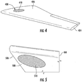
FIG. 4 is a drawing that is useful for understanding an arrangement of an exhaust or diffuser section of a wind powered generator in a TUAV. -
FIG. 5 is a drawing that is useful for understanding an arrangement of an inlet nozzle section of a wind powered generator in a TUAV. -
FIG. 6 is a cross-sectional view of a wing of a TUAV that is useful for understanding a wind powered generator. -
FIG. 7 is a block diagram that is useful for understanding how electric power is generated and used in a TUAV. -
FIG. 8 is a block diagram that is useful for understanding a lifting gas replenishment system (LGRS) which is used in a TUAV. -
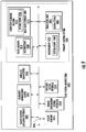
FIG. 9 is a block diagram that is useful for understanding a TUAV system architecture, including a TUAV control system. -
FIGs. 10A, 10B and 10C (collectivelyFIG. 10 ) are a series of drawings which show how the lift provided by the wings of a TUAV work in conjunction with a buoyancy system to facilitate tethered operations under various conditions. -
FIG. 11 is a drawing which is useful for understanding how the TUAV can be used in conjunction with a unmanned underwater vehicle. -
FIG. 12 is a drawing that is useful for understanding how an attachment location of a tether can be moved along a harness for the TUAV. - It will be readily understood that the components of the embodiments as generally described herein and illustrated in the appended figures could be arranged and designed in a wide variety of different configurations. Thus, the following more detailed description of various embodiments, as represented in the figures, is not intended to limit the scope of the present disclosure, but is merely representative of various embodiments. While the various aspects of the embodiments are presented in drawings, the drawings are not necessarily drawn to scale unless specifically indicated.
- A tethered unmanned aerial vehicle (TUAV) is disclosed herein that is buoyant, but includes rigid or substantially rigid wings capable of generating lift. The wings advantageously include one or more control surfaces (e.g. ailerons) so as to allow a flight of the TUAV to be controlled in a manner similar to a conventional fixed wing aircraft. To this end, the TUAV will have an onboard control system which can operate autonomously and/or under the wired or wireless command of a remote control station. The TUAV will also have a wind-based power generation capability that allows the TUAV to generate electric power for potentially indefinite time periods without the need for an onboard fuel reservoir. Further, a lifting gas replenishment system (LGRS) is provided in the TUAV to facilitate generation of at least one gas that is needed to maintain buoyancy.
- An embodiment TUAV as disclosed herein is shown in
FIGs. 1-3 . As shown inFIG. 1 , theTUAV 100 is comprised of afuselage 102 defining a central body of the TUAV, and at least one wing fixed to the fuselage. In the embodiment shown inFIG. 1 , afirst wing 104a, and asecond wing 104b are provided extending bilaterally from the central body of the TUAV. In some embodiments, the first and second wings can be designed as two portions of a single wing that extends through the body of the TUAV. A tether attachment structure (TAS) 110 can be comprised of aharness 109 which is secured to portions of thefuselage 102 and/or thewings tether 108. Thetether 108 is attached at a remote end to aground element 112 which is provided for securing the TUAV to the ground when aloft over an area ofinterest 114. - The
ground element 112 is configured so that it is capable of providing sufficient resistance to forces exerted through the tether so as to facilitate positional control over the geographic location where the tether is attached to the ground. In its simplest form, the ground element can be an anchor which has sufficient mass and/or includes ground engagement structure so that the anchor will remain fixed to a desired ground position. Anchors of this kind are well known and will not be described here in detail. In other embodiments, theground element 112 can be a mobile ground element comprised of a ground mobile vehicle or water mobile vehicle. The various types of ground elements which can be used will be described below in further detail. - The tether can be comprised of a thin flexible elongated wire or filament. The tether can be comprised of one or more strands of a suitable material so that it is capable of withstanding anticipated loads placed upon the tether by the TUAV. If wired control of the TUAV is to be utilized, the tether can include signaling lines for communicating digital data signals to and from the TUAV. For example, the signaling lines can be comprised of one or more conductive wires and/or optical fibers.
- A
payload 106 of the TUAV can include a control system and at least one wired or wireless communication device for receiving flight commands from a remote control station (e.g., a ground based station controlled by a human operating). One ormore sensors 107 can be provided to facilitate control of the TUAV. - A
fuselage 102 of the TUAV can be formed to have an aerodynamic fin shape to control yaw and provide stability about the z axis as shown inFIG. 2 . As such, the fuselage may have a tapered profile which extends from abroader region 210 at the front of the fuselage and tapers to a narrower region at the rear or trailingedge 208 of the fuselage. The fuselage is arranged to accommodate aninternal payload 106 within one or more bays provided for this purpose. Accordingly, thefuselage 102 can be comprised of a lightweight structure having an outer skin to define an aerodynamic shell. The exact type of structure used to form the fuselage is not critical and will depend on various design considerations. However, it will be appreciated that an embodiment fuselage can have a truss structure, a geodesic structure, or may be formed as a monocoque shell. Suitable internal structures used to form the fuselage can be comprised of metals (such as aluminum alloy), wood and/or composite materials. The outer skin of the fuselage can be formed of a suitable material such as lightweight alloy, fabric, composite materials or a combination thereof. For example, embodiment skins can be comprised of a thin film plastic sheets which are comprised of polyethylene terephthalate (PET), polyimide and/or polyester material. - Each of the
wings surface 204a) defined by the wing. As such, thewings - The
wings fuselage 102. An embodiment TUAV shown inFIGs. 1-3 can have a mid-wing design with the wing mounted approximately halfway between the top 214 andbottom 216 of thefuselage 102. Of course, other wing positions are also possible; for example, the TUAV can have a "high wing" design wherein the wing is mounted between the top and mid-point of the fuselage. Various wing structures used in aircraft are well known in the art and therefore will not be described here in detail. However, it will be appreciated thatwings - The design details of the
wings wings - The TUAV also includes at least one movable flight control surface which is capable of selectively varying an attitude of the TUAV in flight in response to a control signal. In an embodiment shown in
FIG. 2 , the at least one movable flight control surface is comprised of ailerons 202a, 202b disposed along the trailing edge of each wing. But the invention is not limited in this regard and additional or alternative movable flight control surfaces can also be provided. For example, such flight control surfaces can in some scenarios include arudder 206 disposed toward a rear of the fuselage at a suitable location (e.g., along a fuselage trailing edge 208) or on an optional boom (not shown) extending from the trailing edge. Although the TUAV is tethered to the ground, a rudder can help provide directional stability for purposes of maintaining a particular vehicle orientation or attitude. In some scenarios, it may also be advantageous to include one or more elevator control surfaces (not shown) which may be disposed at the trailing edge of the fuselage or on the boom. The number and type of flight control surfaces can depend in part on anticipated wind conditions, maneuverability requirements, weight constraints, and cost. The addition of such control surfaces can help control an attitude of the TUAV by controlling pitch, roll and yaw. - The
wings - Referring now to
FIG. 3 it can be observed that the TUAV includes at least onebuoyancy cell 302. ATUAV 100 having a plurality ofbuoyancy cells 302 is illustrated inFIG. 3 . The buoyancy cells are advantageously disposed within the fuselage and configured for containing a lifting gas. For greater stability, the buoyancy cells can be disposed near a top of the fuselage. Further, the buoyancy cells are arranged within the fuselage to take account of the vehicle's center of gravity, whereby the TUAV is maintained in a neutral attitude with the wings level relative to the ground, and the aircraft neither pitched upwardly or downwardly. In some scenarios it may be advantageous to provide additional buoyancy cells disposed in thewings more buoyancy cells 302 will have a combined capability to contain a predetermined volume of lifting gas that is sufficient to provide positive buoyancy for the TUAV when the TUAV is disposed in air and contains a predetermined payload. The exact volume of lifting gas required for this purpose will depend on a particular TUAV design which takes account of the vehicle's size, weight and payload requirements. - The TUAV also includes a
tether attachment structure 110 for securing atether 108 to the TUAV. The tether attachment structure can include aharness 109 comprised of a flexible cable or rigid member that is used to secure thetether 108 to portions of the TUAV. For example, an embodiment TUAV shown inFIG. 1 includes aharness 109 which extends between structural attachment hard points located within each of thewings tether 108. The structural attachment points are advantageously secured to an internal structural element of the wings (e.g. the spar) which is securely attached to thefuselage 102. In some scenarios, theharness 109 can be arranged in the form of an arc which extends in front of the TUAV as shown. - The tether attachment to the harness is advantageously arranged so that the tether can move from side to side of the TUAV along the length of the
harness 109 as indicated byarrows 113. For example, the tether can be attached to the harness by means of a loop orpulley 111 that rides along the length of the harness in directions indicated byarrows 113. This movement of the tether along the harness can facilitate tacking and mobility of the TUAV. More particularly, the movement of the tether attachment point relative to the harness allows the TUAV to operate in a manner similar to sailboat, allowing the TUAV to move in any direction by tacking from one side of the wind to the other. For example, the TUAV can "sail" at an angle to an oncoming wind (e.g. a 45° angle) and can alternate the direction of such angle relative to the wind so as to physically move in a direction into the wind. Of course, the invention is not limited in this regard and thetether 108 can in some embodiments be connected to the TUAV by other suitable means which facilitate such tacking operations. - In an embodiment, the relative position of the tether attachment to the harness is motively regulated or controllably positioned along the harness. This feature enables controlling the position of the tether reaction load relative to the neutral axis of the
TUAV 102. The controlled position along the length of theharness 109 can be facilitated by any suitable means. As an example,FIG. 12 shows an arrangement of aTUAV 1200 comprised of afuselage 1202,wings cables block 1211 is attached between first end portions ofcables Cable 1209a is attached at a second end to acable drum 1222a which can be rotatably driven by a motor (e.g. an electric motor) 1220a. Likewise,cable 1209b is attached at its second end to acable drum 1222b, which is rotatable bymotor 1220b (e.g., an electric motor). Themotors FIG. 12 ). Operation ofmotors cables cable 1209a can be lengthened relative to the length ofcable 1209b as shown inFIG. 12 . When the relative lengths ofcables arrow 1213. Atether cable 1208 is also attached to the block. Accordingly, the position of the tether reaction load (e.g. a ground anchor) can be varied in directions 1212 relative to theneutral axis 1224 of the TUAV. This relative movement of thetether 1208 along the length of the harness formed bycables - The TUAV also includes at least one wind-powered generator. The wind powered generator could be a conventional arrangement comprised of an outboard propeller disposed in the wind which drives an internal generator. However, such an arrangement can be relatively inefficient and have a negative impact on flight performance. Accordingly, it is advantageous to instead provide a wind powered generator which is configured to generate electric power in response to the flow of air across one or both
wings FIGs. 4 and 5 , it can be observed that a TUAV can have upper andlower apertures lower surfaces wing 404. Suitablelouvered members louvers apertures - Referring now to
FIG. 6 it can be observed that a turbine provided within thewing 404 can include aturbine rotor 602 which is disposed for rotation within aturbine housing 603. In an embodiment theturbine rotor 602 can be configured for rotation about an axis z' which is aligned in a direction generally transverse to the major upper and lower wing surfaces 406, 506. Theturbine housing 603 is arranged so that thelower aperture 408 defines a nozzle for providing air to the turbine rotor. The turbine rotor can comprise a plurality of blades and in the most basic embodiment can simply comprise a propeller. The turbine housing also comprises adiffuser section 622 to facilitate the exhaust of air from the turbine to theupper aperture 408. When air is flowing from a leadingsurface 612 of the wing toward a trailing surface 614 (e.g., an air flow caused by wind) the airfoil shape of the wing will cause the formation of a high pressure zone inregion 608 and a low pressure zone inregion 610. In other words, the air pressure above the wing will be lower than the air pressure below the wing as a result of the operation of the airfoil shape. This difference in air pressure will cause a flow of air fromregion 608 toregion 610 as indicated byarrows - The flow of air through the turbine rotor will cause the turbine rotor to rotate. This rotation of the turbine rotor is used to drive an
electric generator 702 as shown inFIG. 7 . The voltage output from the generator can coupled to a voltage regulator 704 which regulates electric power applied to a TUAV primary power bus 706. In some scenarios it can be anticipated that the presence of wind sufficient to drive theturbine rotor 602 may be intermittent. In such instances, at least a portion of the electric power from the voltage regulator 704 can be used to maintain a charge on abattery 708 when sufficient power is being generated. Thereafter, thebattery 708 can be used to supply electricity to the primary power bus 706 when insufficient power is being generated by theelectric power generator 702. - An arrangement as described herein with the turbine rotor disposed inside the wing has several advantages over conventional propeller driven designs. The turbine is a protected assembly because it is disposed within the wing and is more compact as compared to propeller driven generators (which are attached outside the wing with blades extending in directions which are perpendicular to the upper and lower airfoil surfaces). These features facilitate transport of the TUAV with greater ease and time savings in deployment. The architecture disclosed herein also enables the potential to substantially increase the power generation performance over conventional propeller driven designs because the turbo generator operates based on the inherent pressure differential between the upper and lower surfaces of the airfoil. The arrangement disclosed provides more consistent generation / operational performance over a large wind speed range, which is very difficult to achieve with simple propeller driven generator approaches. Further, utilization of the pressure differential created by the airfoil combined with the direct flow vectoring provided by the
louvers turbine rotor 602 for a turbine as described herein can be an extremely low cost part because the individual blade loads and size requirements are far less than those associated with a propeller generator configuration mounted external to the wing. - It is anticipated that a wind-power turbine as described herein can provide power to the TUAV for an extended duration of time, thereby providing the possibility of very long duration flights. But a potentially limiting factor of such long duration flight time is the loss of lifting gas from
buoyancy cells 302. All lighter-than-air vehicles suffer from this loss of lifting gas based on the very small molecule size of hydrogen and helium that is commonly used in such systems. Accordingly, the TUAV advantageously includes a lifting gas replenishment system (LGRS) disposed in the TUAV and configured to extract the lighter than air gas from water vapor that is present in air. Anexemplary LGRS 800 which can be used for this purpose is shown inFIG. 8 . As illustrated therein, theLGRS 800 is comprised of afirst compressor 802, adehumidifier 804,electrolyzer 806 andsecond compressor 808. The LGRS also includes agas storage tank 810, acontrol valve 812, and a compressedair cooling fan 814. - In operation, the
first compressor 802 receives a flow of air from the atmosphere surrounding the TUAV and compresses same using power supplied by the TUAV (e.g., electric power generated using a wind power turbine). The compressed air is then communicated to adehumidifier 804 which extracts water vapor from the compressed flow of air. A flow of air from thefan 814 can be used to cool the compressed gas in the dehumidifier and thereby facilitate condensation of water to liquid form. In some embodiments a flow of air from thefan 814 can also be used to cool thecompressor 802. The water which has been extracted from the air in the dehumidifier is then communicated to theelectrolyzer 806 where electrolysis is used to separate hydrogen and oxygen molecules that comprise the water (H2O). The oxygen from this process can be released to the atmosphere and/or used in a combustion process for other purposes. The hydrogen obtained as a result of this process is communicated to acompressor 808 which compresses the hydrogen for storage in a highly compressed form instorage tank 810. Acontrol valve 812 controls a release or flow of the stored hydrogen for use in the buoyancy cells. For example, the control valve can be under the control of a buoyancy management system. Of course, an LGRS as described herein is not necessary if the TUAV is to be operated for shorter durations flights, and in such cases the various components of an LGRS can be omitted. - Referring now to
FIG. 9 there is shown a block diagram of an exemplary system architecture for a TUAV as disclosed herein. TheTUAV system architecture 1000 can include a primary control system (PCS) 1000 for controlling overall operation of the TUAV. The PCS includes aprocessor unit 1024, a massdata storage unit 1012 which can be a disk drive or a solid state memory, amain memory 1022 and astatic memory 1010, which communicate with each other via adata bus 1026. The processor unit can be one or more devices such as a central processing unit (CPU), an application specific circuit (ASIC), a programmable logic device, or other circuit programmed to perform the functions described herein. - The mass
data storage unit 1012 can comprise a computer readable medium 1014 on which one or more sets of instructions 1008 (e.g., software code) can be stored. These instructions can be provided to facilitate implementation of one or more of the methodologies, procedures, or functions of a TUAV as described herein. Theinstructions 1008 can also reside, completely or at least partially, within themain memory 1022, thestatic memory 1010, and/or within thecontrol unit 1024 during execution thereof. - The TUAV system architecture can also include a flight
control actuator interface 1002, a buoyancy management system (BMS) 1004, awireless transceiver 1006,flight sensors 1016, a powergeneration system interface 1018 andpayload system interface 1020. ThePCS 1001 can communicate with these elements of the TUAV usingdata bus 1026. - The flight
control actuator interface 1002 can include hardware and/or software components which facilitate communications betweenPCS 1001 and one or more flight control actuators. For example, the interface can be used to communicate command signals fromPCS 1001 to flight control actuators so as to cause movement of one or more flight control surfaces as described herein. The flight control actuator interface can also facilitate communication of actuator or control surface position information from the flight control actuators to thePCS 1001. - The
BMS 1004 can be used to help facilitate control over the buoyancy of the TUAV. For example, this system can control the flow of lifting gas to and from the buoyancy cells and onboard storage tanks. As such, theBMS 1004 can control one or more valves which control a flow of lifting gas between the buoyancy cells and onboard gas storage tanks (not shown). TheBMS 1004 can also control the storage and generation of lifting gas by an LGRS as described herein. TheBMS 1004 can operate under the control ofPCS 1001 to maintain a buoyancy requirement at each phase of a TUAV mission. For example, while in flight the BMS can maintain an optimal buoyancy to help maintain the TUAV in a desired altitude and position while minimizing strain on a tether. During recovery operations, the BMS can similarly adjust the buoyancy of the TUAV to facilitate descent of the TUAV while minimizing stress and strain on a tether. The BMS can also monitor available lifting gas stored onboard the TUAV to determine when LGRS operation is needed to generate more lifting gas. -
Flight sensors 1016 are used to monitor one or more aspects of the TUAV to facilitate flight operations while aloft. Exemplary sensors can include altimeters, wind speed sensors, vertical speed sensors, attitude sensors (e.g., to measure pitch, roll and yaw), heading sensors, and so on. Further, to facilitate unmanned flight operations, one or more imaging sensor can be provided among the flight sensors to facilitate flight operations. The outputs from these sensors can be communicated to thePCS 1001 where they can be used to facilitate autonomous flight operations under the control of thePCS 1001. In addition, these sensor outputs can be commutated into a data stream and communicated to a remote ground station using a data link provided bywireless transceiver 1006.Wireless transceiver 1006 facilitates receiving flight control commands for the TUAV from a remote station. Received flight control command signals are communicated to theprocessor unit 1024 where such commands are carried out usingflight control actuators 1002,buoyancy management system 1004 andflight sensors 1016. - Power
generation system interface 1018 facilitates monitoring and control of the power generation system (e.g., a power generation system as disclosed herein with respect toFIGs. 6 and 7 ). For example, the powergeneration system interface 1018 can facilitate control of the turbine,louvers processor unit 1024. In some scenarios, the processor unit can evaluate flight dynamic information to determine when the turbine should be operated for purposes of power generation. The power generation system interface can also facilitate monitoring of the power generation system to determine whether the power generation system is functioning properly, evaluate battery charging requirements, and monitor power bus voltage levels. - A
payload system interface 1020 can be provided to facilitate monitoring of operations associated with a TUAV payload. A wide variety of different payload systems are possible and the invention is not intended to be limited in this regard. However, it should be appreciated that exemplary payloads can include RADAR equipment, communications transponders, optical imagery sensors, infrared sensory equipment, satellite communication equipment, cellular radio transceivers, and so on. In fact, any type of equipment associated with C4ISR operations can be included in the payload to facilitate a particular mission requirement. -
FIGs. 10A, 10B and 10C (collectivelyFIG. 10 ) are a series of drawings which show how the lift force provided by the wings in aTUAV 1100 can work in conjunction with the buoyancy system to facilitate tethered operations under various conditions. As shown inFIGs. 10B the lift force provided by the rigid or near rigid wing includes vector force components which are directed in the +z and +x directions. Accordingly, there is a first vector force component 1 102a that urges theTUAV 1110 upward (in the +z direction) and a secondvector force component 1102b that urges the TUAV forward (in the +x direction). A detailed discussion of wing physics is beyond the scope of the invention. However, it will be appreciated that a lifting force provided by an airfoil wing will act against a reaction force provided by the tether to result in a net force in a forward vector direction which is into the direction of the oncoming wind. This forward force vector is similar to the forward force vector achieved by a sailboat, whereby the tether of TUAV functions in a manner which is similar to that of a sailboat keel, and helps drive the TUAV forward. - In the presence of higher wind velocity, the wings provide greater magnitude lifting force such that the first and second vector force components increase in magnitude. Accordingly, the second
vector force component 1102a can be used advantageously in the embodiments described herein to help cancel a drag load when working cooperatively with thetether 1108. When the wind conditions are moderate as shown inFIG. 10B , the secondvector force component 1102b provides a moderate amount of force in the forward (+x) direction to reduce the drag exerted on thetether 1108. As wind velocity increases, the magnitude of secondvector force component 1102b also increases so as to further counteract the drag exerted on the tether. The wings of the TUAV are advantageously designed such that the drag, buoyancy and lifting forces balance to reduce tether loading and maintain a more consistent operating attitude across a broad range of wind conditions. This gives the TUAV 1100 a broader operational capability as compared to conventional tethered aerostats while still maintaining, longer duration unattended flight times exceeding that which is possible with conventional UAVs. -
FIG. 10A-10C also illustrate certain alterative arrangements for securing thetether 1008 to a ground reaction element. InFIG. 10A it can be observed that the tether can optionally be secured to an upper portion of rigid or stayedtower 1110. In other embodiments, it can be advantageous to secure an end of the tether to an autonomous unmanned ground vehicle (UGV) 1112, thereby facilitating autonomous mobile operations of the TUAV. In other words, the location where the tether is fixed to the ground can be changed by operating the propulsion system of the UGV to changes its geographic location on the surface. Power for the UGV can be provided to the UGV from the TUAV by means of conductive wires included in the tether. Alternatively, the tether can be used to apply a motive force to the UGV. The UGV can have an onboard generator driven by rotation of wheels which roll on the ground. The UGV could then generate its own power by means of the onboard generator as the UGV is pulled along by the TUAV. In scenarios where a UGV is used as the means to secure the tether to the ground, the wings and buoyancy system in the TUAV can be used to help ensure that the lifting forces applied to the UGV through thetether 1108 do not exceed the ground holding ability of the UGV. However, there may be some scenarios where it is desirable to control the TUAV so its lift actually exceeds such ground holding ability so that the UGV can be carried over areas where it cannot otherwise travel. For example, small bodies of water could be traversed by allowing the lift of the TUAV to actually carry the UGV aloft for some distance. - According to a further aspect, the UGV in
FIG. 10C could be replaced by an autonomous water vehicle such as an unmanned underwater vehicle (UUV) shown inFIG. 11 . More particularly, aTUAV 1100 could be attached by means of atether 1108 toUUV 1200. TheUUV 1200 can comprise a sub-surface body containing an underwater payload. The sub-surface body can have invertedhydrofoil planes tether 1108. The inverted hydrofoil planes also provide lateral resistance to counter a lateral force component of aerodynamic lift generated by theTUAV 1100. The UUV can be advantageously equipped with a propulsion assembly (e.g., a motor, power source and propeller) to provide mobility for the UUV so that the geographic location of the tether point can be moved as necessary. - Power for the UUV can be provided in a manner similar to the UGV as described above. For example, conductive wires included in the tether can carry electric power from the TUAV to the UUV. Alternatively, the tether can be used to apply a motive force to the UUV. The UUV can have an onboard generator driven by rotation of an outboard propeller which is rotated as the UUV is moved through the water. The UUV could then generate its own power by means of the onboard generator as the UUV is pulled along by the TUAV.
- In scenarios where a UUV is used as the means to secure the tether to the surface, the wings and buoyancy system in the TUAV can be used to help ensure that the lifting forces applied to the UUV through the
tether 1108 do not exceed the holding ability of the UUV. Likewise the hydrofoil planes of the UUV can be controlled to facilitate such holding ability. However, there may be some scenarios where it is desirable to control the TUAV so that the lifting force it exerts through the tether actually exceeds such holding ability for short durations of time. Consequently, the UUV can be carried aloft for some distance and then returned to the water so that the UUV can be repositioned. - The autonomous water vehicle can also be one which is designed to operate on the surface of a body of water. The water vehicle in such scenarios can be any suitable floating vehicle arrangement such as a mono-hull boat or multi-hull boat (such as a catamaran). The water vehicle would function in much the same way as the UUV except that it would operate on the surface of the water instead of beneath the surface.
Claims (9)
- A tethered unmanned aerial vehicle, i.e. TUAV (100), comprising:a fuselage (102) defining a central body of the TUAV (100);at least one wing (104a, 104b) fixed to the fuselage (102) and comprising an airfoil shaped body capable of producing lift in response to a flow of air across a major wing surface;at least one flight control surface configured to selectively vary an attitude of the TUAV (100) in flight in response to a control signal;at least one buoyancy cell (302) disposed within the fuselage (102) and configured for containing a lighter than air gas, the buoyancy cell (302) having a predetermined volume sufficient to provide a positive buoyancy for the TUAV (100) when the TUAV (100) is disposed in air;a harness (109) secured to the TUAV (100), the harness (109) including a tether attachment structure (110) which facilitates attachment of the harness (109) to a tether (108) having an elongated flexible configuration, said tether capable of extending from the TUAV (100) to the ground when the TUAV (100) is aloft;at least one wind-powered generator integrated with the TUAV (100) and configured to generate electric power in response to the flow of air across said at least one wing (104a, 104b) when the TUAV (100) is aloft;characterized by comprising a lifting gas replenishment system (800), i.e. LGRS, disposed in the TUAV (100) and configured to extract the lighter than air gas from air, and wherein the LGRS (800) comprises a first compressor (802), a dehumidifier (804), an electrolyzer (806), a second compressor (808), a gas storage tank (810), a control valve (812), and a compressed air cooling fan (814).
- The TUAV (100) according to claim 1, wherein the at least one flight control surface is selected from the group consisting of an aileron, an elevator and a rudder.
- The TUAV (100) according to claim 2, further comprising a control system responsive to at least one control signal and configured to control at least one of the flight control surfaces while the TUAV (100) is in flight.
- The TUAV (100) according to claim 1, wherein the at least one wind-powered generator is disposed in the at least one wing (104a, 104b), and is responsive to a pressure differential between opposing major surfaces forming the airfoil shaped body to drive a turbine.
- The TUAV (100) according to claim 1, wherein the at least one wing (104a, 104b) is a rigid structure.
- The TUAV (100) according to claim 1, wherein the harness (109) is comprised of at least one motive element responsive to a TUAV control system and configured to dynamically facilitate a controlled movement of the tether attachment structure (110) relative to a TUAV neutral axis.
- A method for providing an airborne platform, comprising:maintaining a tethered unmanned aerial vehicle, i.e. TUAV (100) aloft using at least one buoyancy cell (302) disposed within a fuselage (102) of the TUAV (100) to contain a predetermined volume of lighter-than-air gas sufficient to provide a positive buoyancy for the TUAV (100) when the TUAV (100) is disposed in air;using at least one wing fixed (104a, 104b) to the fuselage (102) to exert a lifting force on the TUAV (100) while aloft in response to a flow of air across the at least one wing caused by the presence of wind;maintaining the TUAV (100) within a limited range of a geographic positions over a ground surface by securing the TUAV (100) to the ground using a tether (108);controlling a geographic position of the TUAV (100) within the limited range of geographic positions while in the presence of wind by selectively varying a position of at least one flight control surface of the TUAV (100) in response to a control signal;generating electrical power onboard the TUAV (100) in response to the flow of air across the at least one wing (104a, 104b);characterized by comprising extracting the lighter than air gas from air and replenishing the TUAV (100) with the lighter than air gas by a lifting gas replenishment system (800), i.e. LGRS comprising a first compressor (802), a dehumidifier (804), an electrolyzer (806), a second compressor (808), a gas storage tank (810), a control valve (812), and a compressed air cooling fan (814).
- The method according to claim 7, further comprising securing an end of the tether (108) opposed from the TUAV (100) to an unmanned vehicle and selectively varying a geographic position of the unmanned vehicle to vary an area of operations of the TUAV (100).
- The method according to claim 8, wherein the unmanned vehicle is selected from the group consisting of an unmanned water surface operating vehicle and an unmanned underwater vehicle (UUV).
Applications Claiming Priority (1)
| Application Number | Priority Date | Filing Date | Title |
|---|---|---|---|
| US15/243,324 US10065738B2 (en) | 2016-08-22 | 2016-08-22 | Tethered unmanned aerial vehicle |
Publications (2)
| Publication Number | Publication Date |
|---|---|
| EP3287358A1 EP3287358A1 (en) | 2018-02-28 |
| EP3287358B1 true EP3287358B1 (en) | 2020-08-26 |
Family
ID=59034424
Family Applications (1)
| Application Number | Title | Priority Date | Filing Date |
|---|---|---|---|
| EP17000982.3A Active EP3287358B1 (en) | 2016-08-22 | 2017-06-09 | Tethered unmanned aerial vehicle |
Country Status (2)
| Country | Link |
|---|---|
| US (1) | US10065738B2 (en) |
| EP (1) | EP3287358B1 (en) |
Families Citing this family (20)
| Publication number | Priority date | Publication date | Assignee | Title |
|---|---|---|---|---|
| US10315762B2 (en) * | 2014-05-21 | 2019-06-11 | Rutgers, The State University Of New Jersey | Unmanned air and underwater vehicle |
| GB201617803D0 (en) * | 2016-10-21 | 2016-12-07 | Seamach Ltd | A floating ducted wind turbine and semi-submersible support platform |
| WO2018081879A1 (en) * | 2016-11-07 | 2018-05-11 | ALTAVE INDÚSTRIA, COMÉRCIO E EXPORTAçÃO DE AERONAVES LTDA-ME | Tethered aerial system and tether cable |
| US10317904B2 (en) * | 2017-05-05 | 2019-06-11 | Pinnacle Vista, LLC | Underwater leading drone system |
| US10349649B2 (en) * | 2017-05-25 | 2019-07-16 | Cixi Haosheng Electronics & Hardware Co., Ltd. | Animal trap device |
| US10202178B2 (en) * | 2017-06-23 | 2019-02-12 | Hamilton Sundstrand Corporation | Unmanned underwater vehicle propulsion system including an AC power distribution bus |
| US10769684B1 (en) | 2017-10-03 | 2020-09-08 | Wells Fargo Bank, N.A. | Property assessment system with buoyancy adjust device |
| US10737783B2 (en) | 2018-01-16 | 2020-08-11 | RSQ-Systems SPRL | Control systems for unmanned aerial vehicles |
| CN108482621B (en) * | 2018-02-23 | 2020-02-14 | 哈尔滨工业大学(威海) | Floating antenna system applied to diving device |
| US10696396B2 (en) * | 2018-03-05 | 2020-06-30 | Rsq-Systems Us Llc | Stability systems for tethered unmanned aerial vehicles |
| CN108438198A (en) * | 2018-03-31 | 2018-08-24 | 丹阳昊天飞行器技术有限公司 | A kind of pulley buncher |
| US10773800B2 (en) * | 2018-07-26 | 2020-09-15 | RSQ-Systems SPRL | Vehicle-based deployment of a tethered surveillance drone |
| US11242125B2 (en) * | 2018-10-09 | 2022-02-08 | Onward Technologies, Llc | Adaptive harness to stabilize airships in high winds and method |
| US20200255145A1 (en) * | 2019-02-11 | 2020-08-13 | Hybrid Robotics, Inc. | System and method for underwater deployment of a payload |
| US11745868B2 (en) * | 2019-02-20 | 2023-09-05 | Shanghai Autoflight Co., Ltd. | Amphibious aerial vehicle |
| CN111688920B (en) * | 2019-02-20 | 2024-02-02 | 上海峰飞航空科技有限公司 | VTOL fixed wing flight platform system |
| CN110318932A (en) * | 2019-06-05 | 2019-10-11 | 中国航天空气动力技术研究院 | A kind of multi-wall interference for underwater power generation |
| NO346108B1 (en) * | 2020-04-15 | 2022-02-21 | Offshore Power Plant As | Floating installation for energy harvesting |
| KR102264137B1 (en) * | 2020-09-22 | 2021-06-22 | 대한민국(기상청 국립기상과학원장) | Rotating gas injection device for preventing damage to rawinsonde balloon |
| WO2023118830A1 (en) | 2021-12-24 | 2023-06-29 | Tethercells Limited | Tethered aerostat |
Family Cites Families (10)
| Publication number | Priority date | Publication date | Assignee | Title |
|---|---|---|---|---|
| GB2212563A (en) | 1987-11-23 | 1989-07-26 | Lothar Louis Pohl | Balloon mounted wind-power plant |
| WO2007051034A2 (en) | 2005-10-28 | 2007-05-03 | Quantum Industrial Corporation | Static dynamic wind machine |
| US20110101692A1 (en) | 2008-07-16 | 2011-05-05 | Nykolai Bilaniuk | Airborne wind powered generator |
| US8109711B2 (en) * | 2008-07-18 | 2012-02-07 | Honeywell International Inc. | Tethered autonomous air vehicle with wind turbines |
| US20110192938A1 (en) * | 2010-02-09 | 2011-08-11 | Northrop Grumman Systems Corporation | Wind power generation system for lighter than air (lta) platforms |
| GB201004803D0 (en) * | 2010-03-23 | 2010-05-05 | Deakin Nicholas J | Aerial vehicle and method of flight |
| US20110267241A1 (en) * | 2010-05-03 | 2011-11-03 | Thomas Grimm | Multi-Mission Frameless Airship Platform |
| US9631603B2 (en) * | 2014-08-20 | 2017-04-25 | Don Allen Harwood | Wing with slipstream turbine |
| WO2016059040A1 (en) * | 2014-10-14 | 2016-04-21 | Twingtec Ag | Flying apparatus |
| US20160207626A1 (en) | 2015-01-21 | 2016-07-21 | Glen R. Bailey | Airborne Surveillance Kite |
-
2016
- 2016-08-22 US US15/243,324 patent/US10065738B2/en active Active
-
2017
- 2017-06-09 EP EP17000982.3A patent/EP3287358B1/en active Active
Non-Patent Citations (1)
| Title |
|---|
| None * |
Also Published As
| Publication number | Publication date |
|---|---|
| US10065738B2 (en) | 2018-09-04 |
| US20180050797A1 (en) | 2018-02-22 |
| EP3287358A1 (en) | 2018-02-28 |
Similar Documents
| Publication | Publication Date | Title |
|---|---|---|
| EP3287358B1 (en) | Tethered unmanned aerial vehicle | |
| US9745042B2 (en) | Airship including aerodynamic, floatation, and deployable structures | |
| US7306187B2 (en) | Inflatable endurance unmanned aerial vehicle | |
| ES2464570T3 (en) | Lenticular Aircraft | |
| JP6426165B2 (en) | Hybrid VTOL machine | |
| US7530527B2 (en) | Method and device for launching aerial vehicles | |
| US6581873B2 (en) | Hybrid winged airship (dynastat) | |
| Ilieva et al. | A critical review of propulsion concepts for modern airships | |
| CN104925243B (en) | A kind of variable inflated type buoyance lift integration stratospheric airship of span | |
| US20070102571A1 (en) | Airship for lifting heavy loads & methods of operation | |
| NZ509377A (en) | Balloon trajectory control system characterised by a tethered frame further characterised by a flap (rudder), a fuselage and sail (lift generating device) | |
| CA2493466C (en) | Dual hull airship controlled by thrust vectoring | |
| US20160229518A1 (en) | Hybrid lighter-than-air vehicle | |
| CN115867484A (en) | Tactical mixed stratospheric airship | |
| CA2817640A1 (en) | Sail-equipped amphibious aerostat or dirigible |
Legal Events
| Date | Code | Title | Description |
|---|---|---|---|
| PUAI | Public reference made under article 153(3) epc to a published international application that has entered the european phase |
Free format text: ORIGINAL CODE: 0009012 |
|
| STAA | Information on the status of an ep patent application or granted ep patent |
Free format text: STATUS: REQUEST FOR EXAMINATION WAS MADE |
|
| 17P | Request for examination filed |
Effective date: 20170609 |
|
| AK | Designated contracting states |
Kind code of ref document: A1 Designated state(s): AL AT BE BG CH CY CZ DE DK EE ES FI FR GB GR HR HU IE IS IT LI LT LU LV MC MK MT NL NO PL PT RO RS SE SI SK SM TR |
|
| AX | Request for extension of the european patent |
Extension state: BA ME |
|
| STAA | Information on the status of an ep patent application or granted ep patent |
Free format text: STATUS: EXAMINATION IS IN PROGRESS |
|
| 17Q | First examination report despatched |
Effective date: 20190731 |
|
| RIC1 | Information provided on ipc code assigned before grant |
Ipc: B64B 1/58 20060101ALI20200327BHEP Ipc: B64C 39/02 20060101ALI20200327BHEP Ipc: B64B 1/06 20060101AFI20200327BHEP |
|
| GRAP | Despatch of communication of intention to grant a patent |
Free format text: ORIGINAL CODE: EPIDOSNIGR1 |
|
| STAA | Information on the status of an ep patent application or granted ep patent |
Free format text: STATUS: GRANT OF PATENT IS INTENDED |
|
| INTG | Intention to grant announced |
Effective date: 20200511 |
|
| GRAS | Grant fee paid |
Free format text: ORIGINAL CODE: EPIDOSNIGR3 |
|
| GRAA | (expected) grant |
Free format text: ORIGINAL CODE: 0009210 |
|
| STAA | Information on the status of an ep patent application or granted ep patent |
Free format text: STATUS: THE PATENT HAS BEEN GRANTED |
|
| AK | Designated contracting states |
Kind code of ref document: B1 Designated state(s): AL AT BE BG CH CY CZ DE DK EE ES FI FR GB GR HR HU IE IS IT LI LT LU LV MC MK MT NL NO PL PT RO RS SE SI SK SM TR |
|
| REG | Reference to a national code |
Ref country code: GB Ref legal event code: FG4D |
|
| REG | Reference to a national code |
Ref country code: CH Ref legal event code: EP |
|
| REG | Reference to a national code |
Ref country code: DE Ref legal event code: R096 Ref document number: 602017022196 Country of ref document: DE |
|
| REG | Reference to a national code |
Ref country code: AT Ref legal event code: REF Ref document number: 1306126 Country of ref document: AT Kind code of ref document: T Effective date: 20200915 |
|
| REG | Reference to a national code |
Ref country code: IE Ref legal event code: FG4D |
|
| REG | Reference to a national code |
Ref country code: LT Ref legal event code: MG4D |
|
| PG25 | Lapsed in a contracting state [announced via postgrant information from national office to epo] |
Ref country code: FI Free format text: LAPSE BECAUSE OF FAILURE TO SUBMIT A TRANSLATION OF THE DESCRIPTION OR TO PAY THE FEE WITHIN THE PRESCRIBED TIME-LIMIT Effective date: 20200826 Ref country code: NO Free format text: LAPSE BECAUSE OF FAILURE TO SUBMIT A TRANSLATION OF THE DESCRIPTION OR TO PAY THE FEE WITHIN THE PRESCRIBED TIME-LIMIT Effective date: 20201126 Ref country code: GR Free format text: LAPSE BECAUSE OF FAILURE TO SUBMIT A TRANSLATION OF THE DESCRIPTION OR TO PAY THE FEE WITHIN THE PRESCRIBED TIME-LIMIT Effective date: 20201127 Ref country code: BG Free format text: LAPSE BECAUSE OF FAILURE TO SUBMIT A TRANSLATION OF THE DESCRIPTION OR TO PAY THE FEE WITHIN THE PRESCRIBED TIME-LIMIT Effective date: 20201126 Ref country code: SE Free format text: LAPSE BECAUSE OF FAILURE TO SUBMIT A TRANSLATION OF THE DESCRIPTION OR TO PAY THE FEE WITHIN THE PRESCRIBED TIME-LIMIT Effective date: 20200826 Ref country code: LT Free format text: LAPSE BECAUSE OF FAILURE TO SUBMIT A TRANSLATION OF THE DESCRIPTION OR TO PAY THE FEE WITHIN THE PRESCRIBED TIME-LIMIT Effective date: 20200826 Ref country code: PT Free format text: LAPSE BECAUSE OF FAILURE TO SUBMIT A TRANSLATION OF THE DESCRIPTION OR TO PAY THE FEE WITHIN THE PRESCRIBED TIME-LIMIT Effective date: 20201228 Ref country code: HR Free format text: LAPSE BECAUSE OF FAILURE TO SUBMIT A TRANSLATION OF THE DESCRIPTION OR TO PAY THE FEE WITHIN THE PRESCRIBED TIME-LIMIT Effective date: 20200826 |
|
| REG | Reference to a national code |
Ref country code: NL Ref legal event code: MP Effective date: 20200826 |
|
| REG | Reference to a national code |
Ref country code: AT Ref legal event code: MK05 Ref document number: 1306126 Country of ref document: AT Kind code of ref document: T Effective date: 20200826 |
|
| PG25 | Lapsed in a contracting state [announced via postgrant information from national office to epo] |
Ref country code: RS Free format text: LAPSE BECAUSE OF FAILURE TO SUBMIT A TRANSLATION OF THE DESCRIPTION OR TO PAY THE FEE WITHIN THE PRESCRIBED TIME-LIMIT Effective date: 20200826 Ref country code: PL Free format text: LAPSE BECAUSE OF FAILURE TO SUBMIT A TRANSLATION OF THE DESCRIPTION OR TO PAY THE FEE WITHIN THE PRESCRIBED TIME-LIMIT Effective date: 20200826 Ref country code: LV Free format text: LAPSE BECAUSE OF FAILURE TO SUBMIT A TRANSLATION OF THE DESCRIPTION OR TO PAY THE FEE WITHIN THE PRESCRIBED TIME-LIMIT Effective date: 20200826 Ref country code: NL Free format text: LAPSE BECAUSE OF FAILURE TO SUBMIT A TRANSLATION OF THE DESCRIPTION OR TO PAY THE FEE WITHIN THE PRESCRIBED TIME-LIMIT Effective date: 20200826 Ref country code: IS Free format text: LAPSE BECAUSE OF FAILURE TO SUBMIT A TRANSLATION OF THE DESCRIPTION OR TO PAY THE FEE WITHIN THE PRESCRIBED TIME-LIMIT Effective date: 20201226 |
|
| PG25 | Lapsed in a contracting state [announced via postgrant information from national office to epo] |
Ref country code: CZ Free format text: LAPSE BECAUSE OF FAILURE TO SUBMIT A TRANSLATION OF THE DESCRIPTION OR TO PAY THE FEE WITHIN THE PRESCRIBED TIME-LIMIT Effective date: 20200826 Ref country code: DK Free format text: LAPSE BECAUSE OF FAILURE TO SUBMIT A TRANSLATION OF THE DESCRIPTION OR TO PAY THE FEE WITHIN THE PRESCRIBED TIME-LIMIT Effective date: 20200826 Ref country code: RO Free format text: LAPSE BECAUSE OF FAILURE TO SUBMIT A TRANSLATION OF THE DESCRIPTION OR TO PAY THE FEE WITHIN THE PRESCRIBED TIME-LIMIT Effective date: 20200826 Ref country code: EE Free format text: LAPSE BECAUSE OF FAILURE TO SUBMIT A TRANSLATION OF THE DESCRIPTION OR TO PAY THE FEE WITHIN THE PRESCRIBED TIME-LIMIT Effective date: 20200826 Ref country code: SM Free format text: LAPSE BECAUSE OF FAILURE TO SUBMIT A TRANSLATION OF THE DESCRIPTION OR TO PAY THE FEE WITHIN THE PRESCRIBED TIME-LIMIT Effective date: 20200826 |
|
| REG | Reference to a national code |
Ref country code: DE Ref legal event code: R097 Ref document number: 602017022196 Country of ref document: DE |
|
| PG25 | Lapsed in a contracting state [announced via postgrant information from national office to epo] |
Ref country code: ES Free format text: LAPSE BECAUSE OF FAILURE TO SUBMIT A TRANSLATION OF THE DESCRIPTION OR TO PAY THE FEE WITHIN THE PRESCRIBED TIME-LIMIT Effective date: 20200826 Ref country code: AT Free format text: LAPSE BECAUSE OF FAILURE TO SUBMIT A TRANSLATION OF THE DESCRIPTION OR TO PAY THE FEE WITHIN THE PRESCRIBED TIME-LIMIT Effective date: 20200826 Ref country code: AL Free format text: LAPSE BECAUSE OF FAILURE TO SUBMIT A TRANSLATION OF THE DESCRIPTION OR TO PAY THE FEE WITHIN THE PRESCRIBED TIME-LIMIT Effective date: 20200826 |
|
| PG25 | Lapsed in a contracting state [announced via postgrant information from national office to epo] |
Ref country code: SK Free format text: LAPSE BECAUSE OF FAILURE TO SUBMIT A TRANSLATION OF THE DESCRIPTION OR TO PAY THE FEE WITHIN THE PRESCRIBED TIME-LIMIT Effective date: 20200826 |
|
| PLBE | No opposition filed within time limit |
Free format text: ORIGINAL CODE: 0009261 |
|
| STAA | Information on the status of an ep patent application or granted ep patent |
Free format text: STATUS: NO OPPOSITION FILED WITHIN TIME LIMIT |
|
| PG25 | Lapsed in a contracting state [announced via postgrant information from national office to epo] |
Ref country code: IT Free format text: LAPSE BECAUSE OF FAILURE TO SUBMIT A TRANSLATION OF THE DESCRIPTION OR TO PAY THE FEE WITHIN THE PRESCRIBED TIME-LIMIT Effective date: 20200826 |
|
| 26N | No opposition filed |
Effective date: 20210527 |
|
| PG25 | Lapsed in a contracting state [announced via postgrant information from national office to epo] |
Ref country code: SI Free format text: LAPSE BECAUSE OF FAILURE TO SUBMIT A TRANSLATION OF THE DESCRIPTION OR TO PAY THE FEE WITHIN THE PRESCRIBED TIME-LIMIT Effective date: 20200826 |
|
| PG25 | Lapsed in a contracting state [announced via postgrant information from national office to epo] |
Ref country code: MC Free format text: LAPSE BECAUSE OF FAILURE TO SUBMIT A TRANSLATION OF THE DESCRIPTION OR TO PAY THE FEE WITHIN THE PRESCRIBED TIME-LIMIT Effective date: 20200826 |
|
| REG | Reference to a national code |
Ref country code: CH Ref legal event code: PL |
|
| GBPC | Gb: european patent ceased through non-payment of renewal fee |
Effective date: 20210609 |
|
| REG | Reference to a national code |
Ref country code: BE Ref legal event code: MM Effective date: 20210630 |
|
| PG25 | Lapsed in a contracting state [announced via postgrant information from national office to epo] |
Ref country code: LU Free format text: LAPSE BECAUSE OF NON-PAYMENT OF DUE FEES Effective date: 20210609 |
|
| PG25 | Lapsed in a contracting state [announced via postgrant information from national office to epo] |
Ref country code: LI Free format text: LAPSE BECAUSE OF NON-PAYMENT OF DUE FEES Effective date: 20210630 Ref country code: IE Free format text: LAPSE BECAUSE OF NON-PAYMENT OF DUE FEES Effective date: 20210609 Ref country code: GB Free format text: LAPSE BECAUSE OF NON-PAYMENT OF DUE FEES Effective date: 20210609 Ref country code: CH Free format text: LAPSE BECAUSE OF NON-PAYMENT OF DUE FEES Effective date: 20210630 |
|
| PG25 | Lapsed in a contracting state [announced via postgrant information from national office to epo] |
Ref country code: BE Free format text: LAPSE BECAUSE OF NON-PAYMENT OF DUE FEES Effective date: 20210630 |
|
| PG25 | Lapsed in a contracting state [announced via postgrant information from national office to epo] |
Ref country code: HU Free format text: LAPSE BECAUSE OF FAILURE TO SUBMIT A TRANSLATION OF THE DESCRIPTION OR TO PAY THE FEE WITHIN THE PRESCRIBED TIME-LIMIT; INVALID AB INITIO Effective date: 20170609 |
|
| PG25 | Lapsed in a contracting state [announced via postgrant information from national office to epo] |
Ref country code: CY Free format text: LAPSE BECAUSE OF FAILURE TO SUBMIT A TRANSLATION OF THE DESCRIPTION OR TO PAY THE FEE WITHIN THE PRESCRIBED TIME-LIMIT Effective date: 20200826 |
|
| P01 | Opt-out of the competence of the unified patent court (upc) registered |
Effective date: 20230525 |
|
| PGFP | Annual fee paid to national office [announced via postgrant information from national office to epo] |
Ref country code: FR Payment date: 20230626 Year of fee payment: 7 Ref country code: DE Payment date: 20230626 Year of fee payment: 7 |