EP1140251B1 - Opener for opening the membrane of a medicament vessel - Google Patents
Opener for opening the membrane of a medicament vessel Download PDFInfo
- Publication number
- EP1140251B1 EP1140251B1 EP99959932A EP99959932A EP1140251B1 EP 1140251 B1 EP1140251 B1 EP 1140251B1 EP 99959932 A EP99959932 A EP 99959932A EP 99959932 A EP99959932 A EP 99959932A EP 1140251 B1 EP1140251 B1 EP 1140251B1
- Authority
- EP
- European Patent Office
- Prior art keywords
- vessel
- opener
- cutter
- medicament
- water
- Prior art date
- Legal status (The legal status is an assumption and is not a legal conclusion. Google has not performed a legal analysis and makes no representation as to the accuracy of the status listed.)
- Expired - Lifetime
Links
Images







Classifications
-
- A—HUMAN NECESSITIES
- A61—MEDICAL OR VETERINARY SCIENCE; HYGIENE
- A61M—DEVICES FOR INTRODUCING MEDIA INTO, OR ONTO, THE BODY; DEVICES FOR TRANSDUCING BODY MEDIA OR FOR TAKING MEDIA FROM THE BODY; DEVICES FOR PRODUCING OR ENDING SLEEP OR STUPOR
- A61M1/00—Suction or pumping devices for medical purposes; Devices for carrying-off, for treatment of, or for carrying-over, body-liquids; Drainage systems
- A61M1/14—Dialysis systems; Artificial kidneys; Blood oxygenators ; Reciprocating systems for treatment of body fluids, e.g. single needle systems for hemofiltration or pheresis
- A61M1/16—Dialysis systems; Artificial kidneys; Blood oxygenators ; Reciprocating systems for treatment of body fluids, e.g. single needle systems for hemofiltration or pheresis with membranes
- A61M1/1654—Dialysates therefor
- A61M1/1656—Apparatus for preparing dialysates
-
- A—HUMAN NECESSITIES
- A61—MEDICAL OR VETERINARY SCIENCE; HYGIENE
- A61M—DEVICES FOR INTRODUCING MEDIA INTO, OR ONTO, THE BODY; DEVICES FOR TRANSDUCING BODY MEDIA OR FOR TAKING MEDIA FROM THE BODY; DEVICES FOR PRODUCING OR ENDING SLEEP OR STUPOR
- A61M1/00—Suction or pumping devices for medical purposes; Devices for carrying-off, for treatment of, or for carrying-over, body-liquids; Drainage systems
- A61M1/14—Dialysis systems; Artificial kidneys; Blood oxygenators ; Reciprocating systems for treatment of body fluids, e.g. single needle systems for hemofiltration or pheresis
- A61M1/16—Dialysis systems; Artificial kidneys; Blood oxygenators ; Reciprocating systems for treatment of body fluids, e.g. single needle systems for hemofiltration or pheresis with membranes
- A61M1/1654—Dialysates therefor
- A61M1/1656—Apparatus for preparing dialysates
- A61M1/1666—Apparatus for preparing dialysates by dissolving solids
-
- A—HUMAN NECESSITIES
- A61—MEDICAL OR VETERINARY SCIENCE; HYGIENE
- A61M—DEVICES FOR INTRODUCING MEDIA INTO, OR ONTO, THE BODY; DEVICES FOR TRANSDUCING BODY MEDIA OR FOR TAKING MEDIA FROM THE BODY; DEVICES FOR PRODUCING OR ENDING SLEEP OR STUPOR
- A61M1/00—Suction or pumping devices for medical purposes; Devices for carrying-off, for treatment of, or for carrying-over, body-liquids; Drainage systems
- A61M1/14—Dialysis systems; Artificial kidneys; Blood oxygenators ; Reciprocating systems for treatment of body fluids, e.g. single needle systems for hemofiltration or pheresis
- A61M1/16—Dialysis systems; Artificial kidneys; Blood oxygenators ; Reciprocating systems for treatment of body fluids, e.g. single needle systems for hemofiltration or pheresis with membranes
- A61M1/1654—Dialysates therefor
- A61M1/1656—Apparatus for preparing dialysates
- A61M1/1668—Details of containers
-
- B—PERFORMING OPERATIONS; TRANSPORTING
- B67—OPENING, CLOSING OR CLEANING BOTTLES, JARS OR SIMILAR CONTAINERS; LIQUID HANDLING
- B67B—APPLYING CLOSURE MEMBERS TO BOTTLES JARS, OR SIMILAR CONTAINERS; OPENING CLOSED CONTAINERS
- B67B7/00—Hand- or power-operated devices for opening closed containers
- B67B7/38—Power-operated cutting devices
-
- Y—GENERAL TAGGING OF NEW TECHNOLOGICAL DEVELOPMENTS; GENERAL TAGGING OF CROSS-SECTIONAL TECHNOLOGIES SPANNING OVER SEVERAL SECTIONS OF THE IPC; TECHNICAL SUBJECTS COVERED BY FORMER USPC CROSS-REFERENCE ART COLLECTIONS [XRACs] AND DIGESTS
- Y10—TECHNICAL SUBJECTS COVERED BY FORMER USPC
- Y10T—TECHNICAL SUBJECTS COVERED BY FORMER US CLASSIFICATION
- Y10T137/00—Fluid handling
- Y10T137/1624—Destructible or deformable element controlled
- Y10T137/1632—Destructible element
- Y10T137/1692—Rupture disc
- Y10T137/1759—Knife or cutter causes disc to break
-
- Y—GENERAL TAGGING OF NEW TECHNOLOGICAL DEVELOPMENTS; GENERAL TAGGING OF CROSS-SECTIONAL TECHNOLOGIES SPANNING OVER SEVERAL SECTIONS OF THE IPC; TECHNICAL SUBJECTS COVERED BY FORMER USPC CROSS-REFERENCE ART COLLECTIONS [XRACs] AND DIGESTS
- Y10—TECHNICAL SUBJECTS COVERED BY FORMER USPC
- Y10T—TECHNICAL SUBJECTS COVERED BY FORMER US CLASSIFICATION
- Y10T83/00—Cutting
- Y10T83/768—Rotatable disc tool pair or tool and carrier
- Y10T83/7809—Tool pair comprises rotatable tools
- Y10T83/7851—Tool pair comprises disc and cylindrical anvil
-
- Y—GENERAL TAGGING OF NEW TECHNOLOGICAL DEVELOPMENTS; GENERAL TAGGING OF CROSS-SECTIONAL TECHNOLOGIES SPANNING OVER SEVERAL SECTIONS OF THE IPC; TECHNICAL SUBJECTS COVERED BY FORMER USPC CROSS-REFERENCE ART COLLECTIONS [XRACs] AND DIGESTS
- Y10—TECHNICAL SUBJECTS COVERED BY FORMER USPC
- Y10T—TECHNICAL SUBJECTS COVERED BY FORMER US CLASSIFICATION
- Y10T83/00—Cutting
- Y10T83/788—Tool pair comprises rotatable anvil and fixed-type tool
-
- Y—GENERAL TAGGING OF NEW TECHNOLOGICAL DEVELOPMENTS; GENERAL TAGGING OF CROSS-SECTIONAL TECHNOLOGIES SPANNING OVER SEVERAL SECTIONS OF THE IPC; TECHNICAL SUBJECTS COVERED BY FORMER USPC CROSS-REFERENCE ART COLLECTIONS [XRACs] AND DIGESTS
- Y10—TECHNICAL SUBJECTS COVERED BY FORMER USPC
- Y10T—TECHNICAL SUBJECTS COVERED BY FORMER US CLASSIFICATION
- Y10T83/00—Cutting
- Y10T83/808—Two tool pairs, driver for one pair moves relative to driver for other pair
- Y10T83/811—One tool support acts as driver for other
- Y10T83/814—Punch and shear
-
- Y—GENERAL TAGGING OF NEW TECHNOLOGICAL DEVELOPMENTS; GENERAL TAGGING OF CROSS-SECTIONAL TECHNOLOGIES SPANNING OVER SEVERAL SECTIONS OF THE IPC; TECHNICAL SUBJECTS COVERED BY FORMER USPC CROSS-REFERENCE ART COLLECTIONS [XRACs] AND DIGESTS
- Y10—TECHNICAL SUBJECTS COVERED BY FORMER USPC
- Y10T—TECHNICAL SUBJECTS COVERED BY FORMER US CLASSIFICATION
- Y10T83/00—Cutting
- Y10T83/929—Tool or tool with support
- Y10T83/9372—Rotatable type
- Y10T83/9382—Punching plus nonpunching tool
-
- Y—GENERAL TAGGING OF NEW TECHNOLOGICAL DEVELOPMENTS; GENERAL TAGGING OF CROSS-SECTIONAL TECHNOLOGIES SPANNING OVER SEVERAL SECTIONS OF THE IPC; TECHNICAL SUBJECTS COVERED BY FORMER USPC CROSS-REFERENCE ART COLLECTIONS [XRACs] AND DIGESTS
- Y10—TECHNICAL SUBJECTS COVERED BY FORMER USPC
- Y10T—TECHNICAL SUBJECTS COVERED BY FORMER US CLASSIFICATION
- Y10T83/00—Cutting
- Y10T83/929—Tool or tool with support
- Y10T83/9372—Rotatable type
- Y10T83/9387—Punching tool
-
- Y—GENERAL TAGGING OF NEW TECHNOLOGICAL DEVELOPMENTS; GENERAL TAGGING OF CROSS-SECTIONAL TECHNOLOGIES SPANNING OVER SEVERAL SECTIONS OF THE IPC; TECHNICAL SUBJECTS COVERED BY FORMER USPC CROSS-REFERENCE ART COLLECTIONS [XRACs] AND DIGESTS
- Y10—TECHNICAL SUBJECTS COVERED BY FORMER USPC
- Y10T—TECHNICAL SUBJECTS COVERED BY FORMER US CLASSIFICATION
- Y10T83/00—Cutting
- Y10T83/929—Tool or tool with support
- Y10T83/9411—Cutting couple type
- Y10T83/9418—Punching plus nonpunching tool
Definitions
- the invention relates to an apparatus for preparing a fluid for a medical procedure, and an opener for unsealing a vessel containing a medicament.
- US-A-5 788 099 discloses the features in the preamble of claim 1.
- the fluids for dialysis treatment include an acetic acid aqueous solution, which is prepared by diluting an acetic acid stock solution with water, in particular reverse osmosis water (referred to RO water in this specification), and a sodium bicarbonate aqueous solution, which is prepared by dissolving sodium biocarbonate powder in RO water.
- acetic acid aqueous solution which is prepared by diluting an acetic acid stock solution with water, in particular reverse osmosis water (referred to RO water in this specification)
- a sodium bicarbonate aqueous solution which is prepared by dissolving sodium biocarbonate powder in RO water.
- JPP '678 describes an apparatus for preparing sodium bicarbona aqueous solution.
- the apparatus holds an inverted vessel for containing a solid medicament, sodium bicarbona, in the form of a powder or granules, after the vessel is unsealed, so that the contents fall by gravity into a tank which contains water.
- the tank includes an agitator for promoting the mixing of the medicament with the water.
- the apparatus of JPP '678 has a problem that the sodium bicarbona, which has fallen into the tank, cannot be dissolved quickly in the water within the tank since the solid medicament deposits on the bottom of the tank.
- JPP '967 Japanese Patent Publication (Kokai) No. 4-84967 (JPP '967) also describes an apparatus for preparing sodium bicarbona aqueous solution.
- the apparatus is configured to dissolve and wash out sodium bicarbonate contained within a vessel by spraying water into the inverted vessel after the vessel is unsealed.
- dissolving the solid content within the vessel cannot be sufficiently carried out due the small volume available for the dissolving process so that the substantial portion of the sodium bicarbona is washed out of the vessel without dissolving into the water sprayed into the vessel.
- the invention is directed to solve the prior art problems, and to provide an improved apparatus for preparing a fluid for a medical procedure.
- the objective of the invention is to provide an opener for unsealing a vessel containing a medicament used for preparing the fluid for a medical procedure.
- the invention provides an opener for opening the membrane of a vessel which contains at least one medicament in the form of powder and defines a bottom, a side wall, and a top opening which is closed by a membrane for sealing the inside of the vessel after the vessel receives a predetermined amount of the medicament, the opener comprising:
- a tank may be provided for receiving and containing the substances dissolved into the sprayed water.
- the tank is adapted to receive the water from the water source.
- the apparatus further includes a circulation system for supplying the water from the tank to the nozzle.
- the opener may include a housing for enclosing the cutter and the receiving member.
- the holder is vertically displaceable relative to the housing; and the nozzle is attached to the housing to direct the water to the medicament received by the receiving member from outside of the housing.
- the mechanism can include a feed screw vertically supported for rotation; a motor, connected to one end of the feed screw, for rotating the screw; a nut engaging the feed screw; and a member connected between the nut and the holder.
- the cutting edge of the cutter can include a serrated portion provided along the inclined end.
- the serrated portion may be partially provided along the inclined end of the cutter body and, in particular, disposed on the proximal half of the inclined end.
- the serrated portion may be provided all around the inclined end of the cutter body.
- Figure 11 shows an example of an apparatus for preparing a fluid for a medical procedure.
- the apparatus 300 includes a tank 302 for containing the fluid, first and second openers 100 and 200 for opening bottles or first and second vessels 10 and 30 which contain medicament in the forms of powder and liquid, respectively.
- a pump 304 is provided for circulation of the liquid within the apparatus 300.
- RO water is supplied to the tank 302 from a RO water source 320 through a supply conduit 318.
- the RO water contained in the tank 302 is then supplied to the first opener 100 through a main conduit 306 including the pump 304 and a branch conduit 308 connected between the main conduit 306 and the first opener 100.
- the RO water is supplied to the second opener 200 through the main conduit 306 and a branch conduit 314 connected between the main conduit 306 and the second opener 200.
- the first opener 100 opens the seal of the first vessel 10 to remove the medicament in the form of powder from the first vessel 10 and receives it.
- the medicament received by the first opener 100 is dissolved into the OR water supplied to the first opener 100.
- the liquid containing the dissolved medicament flows back to the tank 302 through a return conduit 312.
- the second opener 200 opens the seal of the second vessel 30 to remove the medicament in the form of liquid from the second vessel 30.
- the medicament from the second vessel 30 is mixed with the OR water supplied to the second opener 100, and the mixture flows back to the tank 302 through a return conduit 316.
- the first opener 100 includes a housing defined by upper and lower housings 102 and 104 and a bottom 105 which are connected to each other by a clamp rings 108 and 110.
- the upper housing 102 defines an upper open end 102a for receiving a holder 106.
- the holder 106 is displaceable relative to and within the upper housing 102 in the vertical direction along the central axis "O" of the housing.
- the bottom 105 has an outlet 105a which is adapted for the connection with the conduit 312.
- the holder 106 has a substantially cylindrical side wall 118 defining an upper open end 106a for receiving a fist vessel 10, as described hereinafter, and a neck 114 defining a lower opening end 106b.
- the neck 114 further defines a plurality of inwardly extending lugs 116 which are equally disposed at its upper end and an inwardly extending annular stop 114a adjacent to its lower end.
- the side wall 118 may have a plurality of inclined ribs 118a for aiding the insertion of the first vessel 10.
- the first vessel 10 is adapted to contain solid medicament in the form of power or granular and has a bottom 12, a side wall 14 and a neck 16 which has a radius smaller than the side wall 14.
- the side wall 14 includes a cylindrical portion 14a and a truncated cone portion 14b which connects the end of the upper cylindrical portion 14a opposite to the bottom 12 to one end of the neck 16.
- the neck 16 includes a plurality of engagement portions 20 and screw portions 22.
- Each of the engagement portions includes a guide portion spirally extending along the outer surface of the neck 16, a stop portion 20b provided upper end of the spirally extending guide portion 20a and a protrusion 20c.
- the neck 16 further defines an opening 18 which is air-tightly sealed by a seal in the form of a membrane 24. Though the opening 18, a solid medicament in the form powder or granules is charged into and removed from the first vessel 10.
- the engagement portions 20 are equally disposed on the outer surface of the neck 16 about the axis O2 of the first vessel 10 so that space 16a is provided between the stop 20b and the end of the guide 20a of the adjacent engagement portion 20.
- the screw portions 22 are disposed on the outer surface of the neck 16 to provide the spaces 16a between the adjacent screws 22. The spaces 16a allow the passage of the protrusions 20c when the first vessel 10 is attached to the holder 112.
- Figures 1 and 2 show the first opener 100 with the first vessel 10 mounted thereto.
- the first opener 100 has a cutter 150 which is provided within the housing opposite to the opening 18 of the first vessel 10.
- the upper hosing 102 of the first opener 100 is vertically supported by a stationary frame 112.
- the frame 112 has a pair of arms 112a which extend horizontally along the outer surface of the side wall upper housing 102 and are secured thereto by a plurality of screws 112b (Fig. 2).
- the first opener 100 further includes a mechanism 120 for vertically moving the holder 106.
- the mechanism 120 includes an electric motor 122 attached to the frame 112 by a bracket 122a, and a vertically extending feed screw 124 supported by bearings 130a and 130b at the ends of the screw 124. At the lower end of the feed screw 124 is connected to the shaft 122b of the motor 122 by a coupling 126.
- a nut 128 which engages the feed screw 124 is mounted to a connection member 140.
- the connection member 140 has a pair of arms 140a which extend horizontally along the outer surface of the side wall of the cutter support 160 and are secured thereto by a plurality of screws 140b (Fig. 2).
- the cutter 150 includes a substantially cylindrical cutter body 150 with a lower end defining a threaded portion 154, a flange 155 provided over the threaded portion 154, and an inclined upper end 156 defining an cutting edge.
- the cutter body 152 further includes a plurality of openings 152a (four openings 152a are shown in this embodiment) which define columns 152b supporting the upper portion of the cutter body 152.
- the upper end 156 inclines from a plane perpendicular to the axis of the cutter body 152 by an angle ⁇ (Fig. 5B) of, preferably, 15 - 30 degrees. From the peak of the inclined end 156, a slit 158 vertically extends to one of the opening 152a.
- the inclined end 156 includes a plain cutting edge portion 156a which extend along upper half of the inclined end 156 and a serrated edge portion 156b provided on the lower half of the inclined end 156.
- Figure 5D shows a portion of the serrated portion 156b
- Figure 5E shows a partial side section of the serrated portion 156b along line VE - VE in Figure 5D.
- the pitch "P" (see Figure 5E), the distance between the peaks of the adjacent teeth of the serrated portion 156a, may be 1 - 5 mm, preferably 3 mm, and the depth "D" of the teeth may be 1 - 5 mm, preferably 3 mm.
- the attack angle ⁇ may be 15 - 30 degrees, preferably 20 degrees.
- the serrated portion may be provided all around the inclined end of the cutter body as shown in Figure 6.
- the cutter 150 is attached to and supported by an inner frame 160 which is clamped between the upper and lower housings 102 and 104.
- the inner frame 160 includes a circular base 162 adapted to be clamped by the housings 102 and 104 with seal rings 162a provided therebetween (Figs. 1 and 2), and a central mount 164 which is connected to the circular base 162 by radial spokes 168.
- the central mount 164 has a substantially cylindrical shape with a central bore including a threaded inner surface and a stop 162.
- the cutter 150 is attached to the central mount 164 through the engagement between the threaded portion 154 of the cutter 150 and the threaded inner surface of the central mount 164 with O-rings 150a and 150b clamped therebetween (Figs. 1 and 2).
- a receiving member 170 for receiving the solid medicament falling down from the first vessel 10 when the seal is broken by the first opener 100, is provided between the lower housing 104 and the bottom 105.
- the receiving member 170 includes a screen which can receive the medicament from the first vessel 10.
- the size of the powder of granules of sodium bicarbonate of 200 ⁇ m is generally used for preparing a fluid for dialysis treatment. Therefore, the mesh size of the screen is of at most 200 ⁇ m.
- a screen having a unnecessarily small mesh size, for example under 20 ⁇ m inhibits the flow of the solution through the mesh, which results in increase in the pressure within the housing above the screen to break the seal of the first opener 100.
- the typical mesh size for the screen is of at least 20 ⁇ m, preferably 50 - 150 ⁇ m.
- a water supply nozzle 180 is mounted to the housing of the first opener 100 and connected to the branch conduit 308.
- the water supply nozzle 180 is oriented to the receiving member 170 to direct the water in the form of a spray onto the medicament received on the receiving member 170.
- the first opener 100 further includes a pair of washing nozzles 182 and 184 connected to a branch conduit 310 which is further connected to the main conduit 306 (Fig. 11).
- the washing nozzles 182 and 184 are horizontally oppositely oriented to the cutter 150 to direct the liquid from the tank 302 in the form of a spray for the purpose of washing inside of the housing of the first opener 100 and the cutter 150 after an operation of dissolving the medicament received on the receiving member 170 by spraying the RO water from the water supplying nozzle 180.
- the second opener 200 is configured substantially the same as the first opener 100, except that the second opener 200 is adapted to open the seal of the second vessel 30 for containing a liquid medicament while the first opener 100 is adapted to open the first vessel 10 for containing a solid medicament in the form of power or granular.
- the second opener 200 includes upper housing 202 and lower housing 204 which are connected to each other by a clamp ring 208 to define the housing of the second opener 200.
- the lower housing defines a bottom of the housing and an outlet 204a for connection with the return conduit 316 (Fig. 11).
- the upper housing 202 vertically displaceablly receives a holder 206 for holding the second vessel 30.
- a mechanism 220 which is configured substantially the same as the mechanism 120 of the first opener 100, is provided for vertically moving the holder 206 relative to the upper housing 202.
- a cutter 250 is provided within the housing opposite to the opening of the first vessel 30.
- the cutter 250 is formed substantially the same as the cutter 150 of the first opener 100, except that the cutter 250 of the second opener 200 is formed into one piece while the cutter 150 of the first opener 100 includes two pieces.
- the cutter 250 includes substantially a cylindrical cutter body 252 and a circular base portion 254.
- the cutter body 252 is disposed at the center of the circular base portion 254 and supported by radial spokes 260.
- the circular base portion 254 is adapted to be clamped by the housings 202 and 204 with seal rings provided therebetween (Figs. 1 and 2),
- the cutter body 252 includes an inclined upper end 256 defining an cutting edge.
- the upper end 256 inclines from a plane perpendicular to the axis of the cutter body 252, the same as the cutter of the first opener 100. From the peak of the inclined end 256, a slit 258 vertically extends into the cutter body 252.
- the inclined end 256 includes an plain cutting edge portion 256a which extend along upper half of the inclined end 256 and a serrated edge portion 256b provided on the lower half of the inclined end 256.
- a water supplying nozzle 262 is attached to the bottom of the lower housing 204.
- the water supplying nozzle 262 is oriented substantially to the center of the cutter 250 to direct the water in the form of a spray to the inside of the second vessel 200 through the central bore of the cutter 250 for the purpose of flushing the inside of the second vessel.
- first and second vessels 10 and 30 are mounted to the first and second openers 100 and 200, respectively.
- the first and second vessels 10 and 30 are inverted after their caps (not shown) are removed.
- the necks 16 and 36 of the first and second vessels 10 and 30 are inserted into the bores defined by the necks 114 and 214 of the holders 106 and 206 of the first and second openers 100 and 200, respectively, so that the lugs 116 and 216 pass through the spaces 16a (only the space 16a of the first vessel 10 is shown in the drawings) provided on the outer surfaces of the necks 16 and 36.
- the first and second vessels 10 and 30 are rotated to engage the protrusions 20c (only the protrusions 20c of the first vessel 10 are shown in the drawings) provided on the outer surfaces of the necks 16 and 36 with the lugs 116 and 216. This secures the first and second vessels 10 and 30 to the holders 106 and 206 of the first and second openers 100 and 200.
- first and second vessels 10 and 30 are mounted to the first and second openers 100 and 200, the contents of the first and second vessels 10 and 20 are removed.
- the operation of removing the solid medicament contained within the first vessel will be described.
- the mechanism 120 may be activated by an operator so that the nut 128, the connection member 140 and the holder 106 with the first vessel 10 secured to the holder 106 move downwardly.
- the cutter 150 initiates cutting the membrane 24 in the opposite direction along the inner periphery of the opening 18 of the neck 16.
- Penetration of the inclined end 156 into the membrane 24 proceeds the cutting operation so that the membrane 24 is cut along the inner periphery of the opening 18, except for a portion which is located corresponding to the location of the slit 158.
- the serrated portion 156b aids the cutting performance when the cutting operation is advanced and the tension in the membrane is reduced.
- the mechanism 120 moves the nut 128, the connection member 140, the holder 106 and the holder 106 upwardly from the cutter 150.
- Moving the vessel 10 from the cutter 150 makes the solid medicament within the first vessel 10 to fall down onto the receiving member 170.
- the portion of the membrane 24 which has not been cut by the cutter 150 due to the slit 158 keeps the membrane 24 connected to the neck 16.
- the water is directed to the solid medicament on the receiving member 170 through nozzle 180 to dissolve the solid medicament into the sprayed water.
- the solution flows back to the tank 302 through the outlet 105a and the conduit 312.
- the tank 302 must have a volume at least the volume of the first opener 100 to receive all of the solution at once.
- the water supply through the nozzle 180 is ended and the washing nozzles 182 and 184 start to spray water to clean the inside of the housing 102, 104 and 105 and the cutter 150.
- the openings 152a of the cutter 150 allow the sprayed water to access the inside of the hollow cutter 150 sufficiently.
- the second opener 200 functions substantially the same as the first opener 100 except that, while the first vessel 10 contains a solid medicament, the second vessel 30 mounted to the second opener 200 contains a liquid medicament so that the dissolving operation of the content of the vessel is not required.
- unsealing the membrane attached to the opening of the second vessel 30 removes the liquid medicament from the second vessel 30 so that the liquid medicament flows to the tank 302 through the outlet 204a of the second opener 200 without any operation.
- the water supplying nozzle 262 sprays water toward the inside of the second vessel through the central bore of the cutter 250 to clean the insides of housing 202 and 204, the vessel 30 and the cutter 250.
- the opener 400 includes a housing 402 and a holder 404 to which the vessel 10 is mounted, same as the above-described embodiment. Although it is not shown in Figure 10, the opener 400 also includes a mechanism, substantially the same as the mechanisms 120 and 240.
- the holder 404 includes a first plain gear wheel 406 attached to the top of the holder 404.
- the first gear wheel 406 engages a drive gear wheel 408 attached to a shaft of an electric motor 410.
- the electric motor 410 is securely mounted to a frame 430.
- the rotation of the drive gear wheel 408 rotates the holder 404 through the engagement between the drive gear wheel 408 and the first gear wheel 406.
- the drive gear wheel 408 also engages a second plain gear wheel 412.
- the second plain gear wheel 412 is connected to a bevel gear 414 by a shaft 416 to rotate therewith.
- the bevel gear 414 engages a second bevel gear 418.
- a pinion gear 420 is coaxially connected to the second bevel gear 418 to rotate therewith.
- the pinion gear 420 engages a rack 422 provided on a drive bar 424 which has a stop ring 424a at the end opposite to the rack 422.
- a driven bar 426 which horizontally extends through the housing 402.
- the driven bar 426 is displaceablely supported by a bracket 432 at one end, and the housing 492 at the other end.
- the bracket 432 is connected to the frame 430.
- a piece 428 is secured to the driven bar 428 to move therewith.
- the piece 428 has an aperture (not shown in Figure 10) through which the drive bar 424 extends.
- a coil spring 434 is provided on the driven bar 426 between the piece 428 and the bracket 432.
- a knife 438 which has a cutting edge 438a facing the membrane 24 sealingly closing the opening of the first vessel 10.
- a pair of nozzles 442 is attached to direct water to the solid medicament received by the receiving member 440.
- the first vessel 10 is mounted to the opener 400, as described above.
- the mechanism substantially identical to the mechanism 120 and 220, may be activated by an operator to move the holder 404 downwardly with the first vessel 10 secured to the holder 404.
- the electric motor 410 is activated when the first gear wheel 406 engages the drive gear wheel 408.
- the activation of the electric motor 410 rotates the holder 404 through the engagement between the first gear wheel 406 and the drive gear wheel 408. Further, the activation of the electric motor 410 moves the drive bar 424 to the right in Figure 10 through the gear train of the drive gear wheel 408, the second gear wheel 412, shaft 416, bevel gears 414 and 418, the pinion 420 and the rack 422.
- the cutting edge 438a of the knife 438 contacts the membrane 24 closing the opening the first vessel 10
- the cutting edge 438a of the knife 438 is substantially at the inside of the opening of the first vessel 10.
- the rotation of the holder 404 with the first vessel 10 secured to the holder 404 cuts the membrane 24 along the inner periphery of the opening of the first vessel 10.
- the activation of the electric motor 410 is continued until the membrane 24 is cut along the inner periphery of the opening except for a portion to keep the membrane 24 cut by the knife 438 connected to the neck 16 by the portion.
- the solid medicament within the first vessel 10 falls down into the receiving member 440.
- the water is directed to the solid medicament in the receiving member 440 through nozzles 442 to solve the solid medicament into the sprayed water.
- the solution flows back to the tank 302 through the outlet 402a and the conduit 312.
Landscapes
- Health & Medical Sciences (AREA)
- Urology & Nephrology (AREA)
- Heart & Thoracic Surgery (AREA)
- Engineering & Computer Science (AREA)
- Hematology (AREA)
- General Health & Medical Sciences (AREA)
- Anesthesiology (AREA)
- Biomedical Technology (AREA)
- Emergency Medicine (AREA)
- Life Sciences & Earth Sciences (AREA)
- Animal Behavior & Ethology (AREA)
- Vascular Medicine (AREA)
- Public Health (AREA)
- Veterinary Medicine (AREA)
- Mechanical Engineering (AREA)
- Medical Preparation Storing Or Oral Administration Devices (AREA)
- External Artificial Organs (AREA)
- Control And Other Processes For Unpacking Of Materials (AREA)
Description
- The invention relates to an apparatus for preparing a fluid for a medical procedure, and an opener for unsealing a vessel containing a medicament.
- US-A-5 788 099 discloses the features in the preamble of claim 1.
- Recently, an apparatus for preparing a fluid for a medical procedure, such as dialysis treatment, has been proposed. The fluids for dialysis treatment include an acetic acid aqueous solution, which is prepared by diluting an acetic acid stock solution with water, in particular reverse osmosis water (referred to RO water in this specification), and a sodium bicarbonate aqueous solution, which is prepared by dissolving sodium biocarbonate powder in RO water.
- Japanese Patent Publication (Kokai) No. 5-168678 (JPP '678) describes an apparatus for preparing sodium bicarbona aqueous solution. The apparatus holds an inverted vessel for containing a solid medicament, sodium bicarbona, in the form of a powder or granules, after the vessel is unsealed, so that the contents fall by gravity into a tank which contains water. The tank includes an agitator for promoting the mixing of the medicament with the water. The apparatus of JPP '678 has a problem that the sodium bicarbona, which has fallen into the tank, cannot be dissolved quickly in the water within the tank since the solid medicament deposits on the bottom of the tank.
- Japanese Patent Publication (Kokai) No. 4-84967 (JPP '967) also describes an apparatus for preparing sodium bicarbona aqueous solution. The apparatus is configured to dissolve and wash out sodium bicarbonate contained within a vessel by spraying water into the inverted vessel after the vessel is unsealed. However, with the apparatus of JPP '967, dissolving the solid content within the vessel cannot be sufficiently carried out due the small volume available for the dissolving process so that the substantial portion of the sodium bicarbona is washed out of the vessel without dissolving into the water sprayed into the vessel.
- The invention is directed to solve the prior art problems, and to provide an improved apparatus for preparing a fluid for a medical procedure.
- Further, the objective of the invention is to provide an opener for unsealing a vessel containing a medicament used for preparing the fluid for a medical procedure.
- The invention provides an opener for opening the membrane of a vessel which contains at least one medicament in the form of powder and defines a bottom, a side wall, and a top opening which is closed by a membrane for sealing the inside of the vessel after the vessel receives a predetermined amount of the medicament, the opener comprising:
- a holder for vertically holding the vessel to downwardly orient the opening;
- a cutter, provided beneath the holder for partially cutting the membrane of the vessel held by the holder, along the periphery of the opening;
- a mechanism for vertically moving the holder toward the cutter so that the cutting edge of the cutter pierces and partially separates the membrane from the periphery of the opening whereby the medicament in the vessel falls from the vessel;
- a receiving member provided beneath the cutter, for receiving all amount of the medicament from the vessel; and
- a nozzle for directing water in the form of a spray to the medicament received by the receiving member to dissolve the medicament into the water directed to the medicament; characterized in that
-
- A tank may be provided for receiving and containing the substances dissolved into the sprayed water.
- The tank is adapted to receive the water from the water source. The apparatus further includes a circulation system for supplying the water from the tank to the nozzle.
- The opener may include a housing for enclosing the cutter and the receiving member. The holder is vertically displaceable relative to the housing; and the nozzle is attached to the housing to direct the water to the medicament received by the receiving member from outside of the housing.
- The mechanism can include a feed screw vertically supported for rotation; a motor, connected to one end of the feed screw, for rotating the screw; a nut engaging the feed screw; and a member connected between the nut and the holder.
- The cutting edge of the cutter can include a serrated portion provided along the inclined end. The serrated portion may be partially provided along the inclined end of the cutter body and, in particular, disposed on the proximal half of the inclined end. The serrated portion may be provided all around the inclined end of the cutter body.
- These and other objects and advantages and further description will now be discussed in connection with the drawings in which:
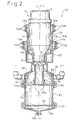
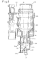
- Figure 1 is a vertical section of an embodiment of an opener according the invention;
- Figure 2 is a vertical section of the opener along line I - I in Figure 1;
- Figure 3 is a vertical section of a holder according to the embodiment shown in Figure 1;
- Figure 4 is a partially enlarged side view of a vessel according to the embodiment shown in Figure 1;
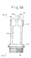
- Figure 5A is a side view of a cutter according to the embodiment shown in Figure 1;
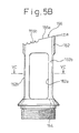
- Figure 5B is another side view of the cutter in the direction VB - VB in Figure 5A;
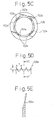
- Figure 5C is a horizontal section of the cutter along line VC - VC in Figure 5A;
- Figure 5D is a partially enlarged section of the cutting edge of the cutter along line VD - VD in Figure 5E;
- Figure 5E is a partially enlarged side view of the cutting edge of the cutter;
- Figure 6 is a perspective view of a cutter according to another embodiment;
- Figure 7 is a cutter support according the embodiment shown in Figure 1;
- Figure 8 is a vertical section of an opener according to another embodiment;
- Figure 9A is a side view of a cutter according to the embodiment shown in Figure 8;
- Figure 9B is another side view of the cutter shown in Figure 9A;
- Figure 9C is a plan view of the cutter viewed in the direction of IXC - IXC in Figure 1A;
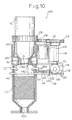
- Figure 10 is an opener according to another embodiment; and
- Figure 11 is an apparatus for preparing a fluid for a medical procedure.
-
- Figure 11 shows an example of an apparatus for preparing a fluid for a medical procedure.
- The
apparatus 300 includes atank 302 for containing the fluid, first andsecond openers second vessels pump 304 is provided for circulation of the liquid within theapparatus 300. RO water is supplied to thetank 302 from aRO water source 320 through asupply conduit 318. The RO water contained in thetank 302 is then supplied to thefirst opener 100 through amain conduit 306 including thepump 304 and abranch conduit 308 connected between themain conduit 306 and thefirst opener 100. Likewise, the RO water is supplied to thesecond opener 200 through themain conduit 306 and a branch conduit 314 connected between themain conduit 306 and thesecond opener 200. - The
first opener 100 opens the seal of thefirst vessel 10 to remove the medicament in the form of powder from thefirst vessel 10 and receives it. The medicament received by thefirst opener 100 is dissolved into the OR water supplied to thefirst opener 100. The liquid containing the dissolved medicament flows back to thetank 302 through areturn conduit 312. - Likewise, the
second opener 200 opens the seal of thesecond vessel 30 to remove the medicament in the form of liquid from thesecond vessel 30. The medicament from thesecond vessel 30 is mixed with the OR water supplied to thesecond opener 100, and the mixture flows back to thetank 302 through areturn conduit 316. - With reference to Figures 1 - 7, the
first opener 100 according to the embodiment of the invention will be described below. - The
first opener 100 includes a housing defined by upper andlower housings upper housing 102 defines an upperopen end 102a for receiving aholder 106. Theholder 106 is displaceable relative to and within theupper housing 102 in the vertical direction along the central axis "O" of the housing. The bottom 105 has anoutlet 105a which is adapted for the connection with theconduit 312. - With reference to Figure 3, the
holder 106 has a substantiallycylindrical side wall 118 defining an upperopen end 106a for receiving afist vessel 10, as described hereinafter, and a neck 114 defining alower opening end 106b. The neck 114 further defines a plurality of inwardly extendinglugs 116 which are equally disposed at its upper end and an inwardly extendingannular stop 114a adjacent to its lower end. Theside wall 118 may have a plurality ofinclined ribs 118a for aiding the insertion of thefirst vessel 10. - The
first vessel 10 is adapted to contain solid medicament in the form of power or granular and has a bottom 12, aside wall 14 and aneck 16 which has a radius smaller than theside wall 14. Theside wall 14 includes acylindrical portion 14a and atruncated cone portion 14b which connects the end of the uppercylindrical portion 14a opposite to the bottom 12 to one end of theneck 16. - With reference to Figure 4, the
neck 16 includes a plurality ofengagement portions 20 andscrew portions 22. Each of the engagement portions includes a guide portion spirally extending along the outer surface of theneck 16, astop portion 20b provided upper end of the spirally extendingguide portion 20a and aprotrusion 20c. Theneck 16 further defines anopening 18 which is air-tightly sealed by a seal in the form of amembrane 24. Though theopening 18, a solid medicament in the form powder or granules is charged into and removed from thefirst vessel 10. - The
engagement portions 20 are equally disposed on the outer surface of theneck 16 about the axis O2 of thefirst vessel 10 so thatspace 16a is provided between thestop 20b and the end of theguide 20a of theadjacent engagement portion 20. Likewise, thescrew portions 22 are disposed on the outer surface of theneck 16 to provide thespaces 16a between the adjacent screws 22. Thespaces 16a allow the passage of theprotrusions 20c when thefirst vessel 10 is attached to theholder 112. - Figures 1 and 2 show the
first opener 100 with thefirst vessel 10 mounted thereto. Thefirst opener 100 has acutter 150 which is provided within the housing opposite to theopening 18 of thefirst vessel 10. - The
upper hosing 102 of thefirst opener 100 is vertically supported by astationary frame 112. Theframe 112 has a pair ofarms 112a which extend horizontally along the outer surface of the side wallupper housing 102 and are secured thereto by a plurality ofscrews 112b (Fig. 2). - The
first opener 100 further includes amechanism 120 for vertically moving theholder 106. Themechanism 120 includes anelectric motor 122 attached to theframe 112 by abracket 122a, and a vertically extendingfeed screw 124 supported bybearings screw 124. At the lower end of thefeed screw 124 is connected to theshaft 122b of themotor 122 by acoupling 126. Anut 128 which engages thefeed screw 124 is mounted to aconnection member 140. Theconnection member 140 has a pair ofarms 140a which extend horizontally along the outer surface of the side wall of thecutter support 160 and are secured thereto by a plurality ofscrews 140b (Fig. 2). - With reference to Figures 5A to 5E, the configuration of the
cutter 150 is described below. - The
cutter 150 includes a substantiallycylindrical cutter body 150 with a lower end defining a threadedportion 154, aflange 155 provided over the threadedportion 154, and an inclinedupper end 156 defining an cutting edge. Thecutter body 152 further includes a plurality ofopenings 152a (fouropenings 152a are shown in this embodiment) which definecolumns 152b supporting the upper portion of thecutter body 152. - The
upper end 156 inclines from a plane perpendicular to the axis of thecutter body 152 by an angle α (Fig. 5B) of, preferably, 15 - 30 degrees. From the peak of theinclined end 156, aslit 158 vertically extends to one of theopening 152a. Theinclined end 156 includes a plaincutting edge portion 156a which extend along upper half of theinclined end 156 and aserrated edge portion 156b provided on the lower half of theinclined end 156. Figure 5D shows a portion of theserrated portion 156b, and Figure 5E shows a partial side section of theserrated portion 156b along line VE - VE in Figure 5D. The pitch "P" (see Figure 5E), the distance between the peaks of the adjacent teeth of theserrated portion 156a, may be 1 - 5 mm, preferably 3 mm, and the depth "D" of the teeth may be 1 - 5 mm, preferably 3 mm. Further, the attack angle β may be 15 - 30 degrees, preferably 20 degrees. Further, the serrated portion may be provided all around the inclined end of the cutter body as shown in Figure 6. - The
cutter 150 is attached to and supported by aninner frame 160 which is clamped between the upper andlower housings inner frame 160 includes acircular base 162 adapted to be clamped by thehousings seal rings 162a provided therebetween (Figs. 1 and 2), and acentral mount 164 which is connected to thecircular base 162 byradial spokes 168. Thecentral mount 164 has a substantially cylindrical shape with a central bore including a threaded inner surface and astop 162. Thecutter 150 is attached to thecentral mount 164 through the engagement between the threadedportion 154 of thecutter 150 and the threaded inner surface of thecentral mount 164 with O-rings - A receiving
member 170, for receiving the solid medicament falling down from thefirst vessel 10 when the seal is broken by thefirst opener 100, is provided between thelower housing 104 and the bottom 105. The receivingmember 170 includes a screen which can receive the medicament from thefirst vessel 10. The size of the powder of granules of sodium bicarbonate of 200 µm is generally used for preparing a fluid for dialysis treatment. Therefore, the mesh size of the screen is of at most 200 µm. On the other hand, a screen having a unnecessarily small mesh size, for example under 20 µm, inhibits the flow of the solution through the mesh, which results in increase in the pressure within the housing above the screen to break the seal of thefirst opener 100. The typical mesh size for the screen is of at least 20µm, preferably 50 - 150µm. - A
water supply nozzle 180 is mounted to the housing of thefirst opener 100 and connected to thebranch conduit 308. Thewater supply nozzle 180 is oriented to the receivingmember 170 to direct the water in the form of a spray onto the medicament received on the receivingmember 170. - The
first opener 100 further includes a pair ofwashing nozzles 182 and 184 connected to abranch conduit 310 which is further connected to the main conduit 306 (Fig. 11). The washing nozzles 182 and 184 are horizontally oppositely oriented to thecutter 150 to direct the liquid from thetank 302 in the form of a spray for the purpose of washing inside of the housing of thefirst opener 100 and thecutter 150 after an operation of dissolving the medicament received on the receivingmember 170 by spraying the RO water from thewater supplying nozzle 180. - With reference to Figures 8 - 9C, the
second opener 200 will be described below. - The
second opener 200 is configured substantially the same as thefirst opener 100, except that thesecond opener 200 is adapted to open the seal of thesecond vessel 30 for containing a liquid medicament while thefirst opener 100 is adapted to open thefirst vessel 10 for containing a solid medicament in the form of power or granular. - The
second opener 200 includesupper housing 202 andlower housing 204 which are connected to each other by aclamp ring 208 to define the housing of thesecond opener 200. The lower housing defines a bottom of the housing and anoutlet 204a for connection with the return conduit 316 (Fig. 11). - The
upper housing 202 vertically displaceablly receives aholder 206 for holding thesecond vessel 30. Amechanism 220, which is configured substantially the same as themechanism 120 of thefirst opener 100, is provided for vertically moving theholder 206 relative to theupper housing 202. - A cutter 250 is provided within the housing opposite to the opening of the
first vessel 30. The cutter 250 is formed substantially the same as thecutter 150 of thefirst opener 100, except that the cutter 250 of thesecond opener 200 is formed into one piece while thecutter 150 of thefirst opener 100 includes two pieces. The cutter 250 includes substantially acylindrical cutter body 252 and acircular base portion 254. Thecutter body 252 is disposed at the center of thecircular base portion 254 and supported byradial spokes 260. Thecircular base portion 254 is adapted to be clamped by thehousings - The
cutter body 252 includes an inclinedupper end 256 defining an cutting edge. Theupper end 256 inclines from a plane perpendicular to the axis of thecutter body 252, the same as the cutter of thefirst opener 100. From the peak of theinclined end 256, aslit 258 vertically extends into thecutter body 252. Theinclined end 256 includes an plaincutting edge portion 256a which extend along upper half of theinclined end 256 and aserrated edge portion 256b provided on the lower half of theinclined end 256. - A
water supplying nozzle 262 is attached to the bottom of thelower housing 204. Thewater supplying nozzle 262 is oriented substantially to the center of the cutter 250 to direct the water in the form of a spray to the inside of thesecond vessel 200 through the central bore of the cutter 250 for the purpose of flushing the inside of the second vessel. - The functional operation of the apparatus for preparing a fluid for a medical procedure of the invention will be described below.
- First, the first and
second vessels second openers second vessels necks second vessels holders second openers lugs spaces 16a (only thespace 16a of thefirst vessel 10 is shown in the drawings) provided on the outer surfaces of thenecks necks stops holders second vessels protrusions 20c (only theprotrusions 20c of thefirst vessel 10 are shown in the drawings) provided on the outer surfaces of thenecks lugs second vessels holders second openers - After the first and
second vessels second openers second vessels - The
mechanism 120 may be activated by an operator so that thenut 128, theconnection member 140 and theholder 106 with thefirst vessel 10 secured to theholder 106 move downwardly. When thetips 156c of thecutting edge 156a of thecutter 150 contact themembrane 24 closing theopening 18 of thefirst vessel 10, thecutter 150 initiates cutting themembrane 24 in the opposite direction along the inner periphery of theopening 18 of theneck 16. Penetration of theinclined end 156 into themembrane 24 proceeds the cutting operation so that themembrane 24 is cut along the inner periphery of theopening 18, except for a portion which is located corresponding to the location of theslit 158. Theserrated portion 156b aids the cutting performance when the cutting operation is advanced and the tension in the membrane is reduced. - Then, the
mechanism 120 moves thenut 128, theconnection member 140, theholder 106 and theholder 106 upwardly from thecutter 150. Moving thevessel 10 from thecutter 150 makes the solid medicament within thefirst vessel 10 to fall down onto the receivingmember 170. At this time, the portion of themembrane 24 which has not been cut by thecutter 150 due to theslit 158 keeps themembrane 24 connected to theneck 16. The water is directed to the solid medicament on the receivingmember 170 throughnozzle 180 to dissolve the solid medicament into the sprayed water. The solution flows back to thetank 302 through theoutlet 105a and theconduit 312. Thetank 302 must have a volume at least the volume of thefirst opener 100 to receive all of the solution at once. - After the solid medicament is completely solved, the water supply through the
nozzle 180 is ended and thewashing nozzles 182 and 184 start to spray water to clean the inside of thehousing cutter 150. In particular, theopenings 152a of thecutter 150 allow the sprayed water to access the inside of thehollow cutter 150 sufficiently. - The
second opener 200 functions substantially the same as thefirst opener 100 except that, while thefirst vessel 10 contains a solid medicament, thesecond vessel 30 mounted to thesecond opener 200 contains a liquid medicament so that the dissolving operation of the content of the vessel is not required. Thus, unsealing the membrane attached to the opening of thesecond vessel 30 removes the liquid medicament from thesecond vessel 30 so that the liquid medicament flows to thetank 302 through theoutlet 204a of thesecond opener 200 without any operation. After completion of the evacuation of thesecond vessel 30, thewater supplying nozzle 262 sprays water toward the inside of the second vessel through the central bore of the cutter 250 to clean the insides ofhousing vessel 30 and the cutter 250. - With reference to Figure 10, an opener according to another embodiment will be described below.
- The
opener 400 includes ahousing 402 and aholder 404 to which thevessel 10 is mounted, same as the above-described embodiment. Although it is not shown in Figure 10, theopener 400 also includes a mechanism, substantially the same as themechanisms 120 and 240. - The
holder 404 includes a firstplain gear wheel 406 attached to the top of theholder 404. Thefirst gear wheel 406 engages adrive gear wheel 408 attached to a shaft of anelectric motor 410. Theelectric motor 410 is securely mounted to aframe 430. The rotation of thedrive gear wheel 408 rotates theholder 404 through the engagement between thedrive gear wheel 408 and thefirst gear wheel 406. - The
drive gear wheel 408 also engages a secondplain gear wheel 412. The secondplain gear wheel 412 is connected to a bevel gear 414 by ashaft 416 to rotate therewith. The bevel gear 414 engages asecond bevel gear 418. A pinion gear 420 is coaxially connected to thesecond bevel gear 418 to rotate therewith. The pinion gear 420 engages arack 422 provided on adrive bar 424 which has astop ring 424a at the end opposite to therack 422. - Provided beneath the
drive bar 424 is a drivenbar 426 which horizontally extends through thehousing 402. The drivenbar 426 is displaceablely supported by abracket 432 at one end, and the housing 492 at the other end. Thebracket 432 is connected to theframe 430. Apiece 428 is secured to the drivenbar 428 to move therewith. Thepiece 428 has an aperture (not shown in Figure 10) through which thedrive bar 424 extends. Provided on the drive bar between thestop ring 424a and thepiece 428 is acoil spring 434. Likewise, acoil spring 436 is provided on the drivenbar 426 between thepiece 428 and thebracket 432. - Provided on the driven
bar 426 is aknife 438 which has acutting edge 438a facing themembrane 24 sealingly closing the opening of thefirst vessel 10. A receivingmember 440 in the form of a basket, which includes a screen or mesh provided in at least the bottom and a portion of the side wall, is provided beneath theknife 438. A pair ofnozzles 442 is attached to direct water to the solid medicament received by the receivingmember 440. - The functional operation of the
opener 400 will be described below. - The
first vessel 10 is mounted to theopener 400, as described above. After thefirst vessel 10 is mounted to theopener 400, the mechanism, substantially identical to themechanism holder 404 downwardly with thefirst vessel 10 secured to theholder 404. Theelectric motor 410 is activated when thefirst gear wheel 406 engages thedrive gear wheel 408. The activation of theelectric motor 410 rotates theholder 404 through the engagement between thefirst gear wheel 406 and thedrive gear wheel 408. Further, the activation of theelectric motor 410 moves thedrive bar 424 to the right in Figure 10 through the gear train of thedrive gear wheel 408, thesecond gear wheel 412,shaft 416,bevel gears 414 and 418, the pinion 420 and therack 422. When thecutting edge 438a of theknife 438 contacts themembrane 24 closing the opening thefirst vessel 10, thecutting edge 438a of theknife 438 is substantially at the inside of the opening of thefirst vessel 10. The rotation of theholder 404 with thefirst vessel 10 secured to theholder 404 cuts themembrane 24 along the inner periphery of the opening of thefirst vessel 10. - The activation of the
electric motor 410 is continued until themembrane 24 is cut along the inner periphery of the opening except for a portion to keep themembrane 24 cut by theknife 438 connected to theneck 16 by the portion. - When the opening of the
first vessel 10 is unsealed, the solid medicament within thefirst vessel 10 falls down into the receivingmember 440. The water is directed to the solid medicament in the receivingmember 440 throughnozzles 442 to solve the solid medicament into the sprayed water. The solution flows back to thetank 302 through theoutlet 402a and theconduit 312. - It will also be understood by those skilled in the art that the forgoing description is a preferred embodiment of the disclosed device and that various changes and modifications may be made without departing from the scope of the invention as defined in the appended claims.
the receiving member is in the form of a mesh.
Claims (12)
- An opener (100, 200, 400) for opening the membrane of a vessel (10) which contains at least one medicament in the form of powder and defines a bottom (12), a side wall (14), and a top opening (18) which is closed by a membrane (24) for sealing the inside of the vessel (10) after the vessel receives a predetermined amount of the medicament, the opener comprising:characterized in thata holder (106, 404) for vertically holding the vessel to downwardly orient the opening (18);a cutter (150, 250, 438), provided beneath the holder (106, 404) for partially cutting the membrane (24) of the vessel (10) held by the holder (106, 404) along the periphery of the opening (18);a mechanism (120, 240) for vertically moving the holder (106, 404) toward the cutter (150, 250, 438) so that the cutting edge of the cutter pierces and partially separates the membrane (24) from the periphery of the opening (18) whereby the medicament in the vessel (10) falls from the vessel;a receiving member (170, 440) provided beneath the cutter (150, 250, 438), for receiving all amount of the medicament from the vessel (10); anda nozzle (180) for directing water in the form of a spray to the medicament received by the receiving member (170, 440) to dissolve the medicament into the water directed to the medicament;
the receiving member (170, 440) is in the form of a mesh. - An opener (100, 200, 400) according to claim 1 further comprising a housing (102, 202, 402) for enclosing the cutter (150, 250, 438) and the receiving member (170, 440), the holder (106, 404) being vertically displaceable relative to the housing, and the nozzle (180) being attached to the housing to direct the water to the medicament received by the receiving member from outside of the housing.
- An opener (100, 200, 400) according to Claim 1 or 2, wherein the mesh size of the receiving member (170, 440) is of at least 20 µm, preferably 50-150 µm.
- An opener (100, 200, 400) according to any one of Claims 1 to 3, wherein the mechanism (120) comprises a feed screw vertically supported for rotation;
a motor, connected to one end of the feed screw, for rotating the screw;
a nut (128) engaging the feed screw; and
a member (140) connected between the nut and the holder. - An opener according to any one of the preceding claims, characterized in that
the cutter for partially cutting a membrane (24) along a periphery of the opening of the vessel comprises:a cutter body (152) substantially in the form of a hollow cylinder having an inclined end;a cutting edge (156) provided along the inclined end;a slit extending from the inclined end into the cutter body. - An opener according to Claim 5, wherein the cutting edge of the cutter (150, 250, 438) includes a serrated portion (156, 156') provided along the inclined end.
- An opener according to Claim 6, wherein the serrated portion is partially provided along the inclined end of the cutter body.
- An opener according to Claim 7, wherein the serrated portion is disposed on the proximal half of the inclined end.
- An opener according to Claim 6, wherein the serrated portion is provided all around the inclined end of the cutter body.
- An apparatus (300) for preparing a fluid for a medical procedure by mixing of at least one medicament in the form of powder with water sprayed, the apparatus comprising:whereina vessel (10) for holding the medicament, the vessel defining a bottom, a side wall, and a top opening (18) which is closed by a membrane (24) for sealing the inside of the vessel;a source of water (320); anda tank (302) for receiving and containing the substances dissolved in the sprayed water;
the apparatus comprises an opener (100, 200, 400) according to any one of the previous claims. - An apparatus according to Claim 10, wherein the tank (302) is adapted to receive the water from the water source (320); and
the apparatus further comprising a circulating system for supplying the water from the tank to the nozzle. - An apparatus according to Claim 10, for preparing a fluid for a medical procedure by mixing of first and second medicaments with water,
characterized in that
the apparatus comprises a second vessel (30) holding the second medicament, the second vessel defining a bottom, a side wall, and a top opening which is closed by a membrane for sealing the inside of the vessel;
a second opener (200) for opening the membrane of the second vessel (30), the second opener (200) including a second holder (206) for vertically holding the second vessel (30) to downwardly orient the opening;
a second cutter (250), provided beneath the second holder (206), for partially cutting the membrane of the second vessel held by the second holder along the periphery of the opening;
a second mechanism (220) for vertically moving the second holder (206) toward the second cutter so that the cutting edge of the second cutter (250) pierces and partially separates the membrane from the periphery of the opening whereby the second medicament in the second vessel (30) falls from the second vessel; and
a second nozzle (262) for directing water from the source of water in the form of a spray to the inside of the second vessel (30).
Priority Applications (1)
| Application Number | Priority Date | Filing Date | Title |
|---|---|---|---|
| EP04014467A EP1457219A1 (en) | 1998-12-21 | 1999-12-21 | Cutter for partially cutting a membrane |
Applications Claiming Priority (3)
| Application Number | Priority Date | Filing Date | Title |
|---|---|---|---|
| JP36282898 | 1998-12-21 | ||
| JP10362828A JP2000176007A (en) | 1998-12-21 | 1998-12-21 | Dialysate preparation device |
| PCT/JP1999/007165 WO2000037127A1 (en) | 1998-12-21 | 1999-12-21 | An apparatus for preparing a fluid for a medical procedure |
Related Child Applications (1)
| Application Number | Title | Priority Date | Filing Date |
|---|---|---|---|
| EP04014467A Division EP1457219A1 (en) | 1998-12-21 | 1999-12-21 | Cutter for partially cutting a membrane |
Publications (2)
| Publication Number | Publication Date |
|---|---|
| EP1140251A1 EP1140251A1 (en) | 2001-10-10 |
| EP1140251B1 true EP1140251B1 (en) | 2004-07-21 |
Family
ID=18477836
Family Applications (2)
| Application Number | Title | Priority Date | Filing Date |
|---|---|---|---|
| EP99959932A Expired - Lifetime EP1140251B1 (en) | 1998-12-21 | 1999-12-21 | Opener for opening the membrane of a medicament vessel |
| EP04014467A Withdrawn EP1457219A1 (en) | 1998-12-21 | 1999-12-21 | Cutter for partially cutting a membrane |
Family Applications After (1)
| Application Number | Title | Priority Date | Filing Date |
|---|---|---|---|
| EP04014467A Withdrawn EP1457219A1 (en) | 1998-12-21 | 1999-12-21 | Cutter for partially cutting a membrane |
Country Status (12)
| Country | Link |
|---|---|
| US (1) | US7048898B1 (en) |
| EP (2) | EP1140251B1 (en) |
| JP (1) | JP2000176007A (en) |
| KR (1) | KR20010101180A (en) |
| CN (2) | CN1541933A (en) |
| AU (1) | AU759206B2 (en) |
| CA (1) | CA2356365A1 (en) |
| DE (1) | DE69918860T2 (en) |
| ID (1) | ID28938A (en) |
| MY (1) | MY129614A (en) |
| TW (1) | TW418097B (en) |
| WO (1) | WO2000037127A1 (en) |
Families Citing this family (12)
| Publication number | Priority date | Publication date | Assignee | Title |
|---|---|---|---|---|
| HK1047899B (en) | 2000-02-16 | 2006-01-13 | 帝人株式会社 | Dialyzing fluid preparing device and powdery dialyzing fluid preparing chemical |
| JP2001346868A (en) * | 2000-06-12 | 2001-12-18 | Teijin Ltd | Dialysate preparation device and artificial dialysis device |
| ES2256348T3 (en) * | 2002-03-11 | 2006-07-16 | Fresenius Medical Care Deutschland Gmbh | CONNECTOR, CONTAINER WITH SUCH CONNECTOR AND FLUID PREPARATION DEVICE WITH COUPLING CONNECTOR FOR SUCH CONTAINER. |
| AR037133A1 (en) * | 2003-02-04 | 2004-10-27 | Fresenius Medical Care Argentina | Two-compartment bag for hemodialysis machines and their manufacturing procedure |
| JP5192936B2 (en) * | 2008-07-31 | 2013-05-08 | オリンパスメディカルシステムズ株式会社 | Endoscope cleaning disinfection device |
| US8852442B2 (en) | 2010-03-08 | 2014-10-07 | Delaware Capital Formation, Inc. | Solid chemical dissolver and methods |
| CN104349845B (en) * | 2012-02-21 | 2018-06-29 | 艺康美国股份有限公司 | Controlled dissolution solid product dispenser |
| CN102847567A (en) * | 2012-08-24 | 2013-01-02 | 浙江硕华医用塑料有限公司 | Microscale sampling rod |
| CN102989047A (en) * | 2012-12-25 | 2013-03-27 | 董大泉 | Household peritoneal dialysis liquid manufacture equipment |
| EP2886139A1 (en) * | 2013-12-20 | 2015-06-24 | Fresenius Medical Care Deutschland GmbH | Container |
| CN113558988B (en) * | 2021-08-27 | 2023-07-25 | 四川大学华西第二医院 | A device for dispensing medicine for pediatric medicine |
| DE102022133294A1 (en) * | 2022-12-14 | 2024-06-20 | Dmg Mori Additive Gmbh | Tilt protection for material powder bottles |
Family Cites Families (14)
| Publication number | Priority date | Publication date | Assignee | Title |
|---|---|---|---|---|
| US3168379A (en) | 1957-12-27 | 1965-02-02 | Morton Salt Co | Apparatus and method of producing brine |
| US3581605A (en) * | 1969-10-29 | 1971-06-01 | Allied Chem | Opening device for membrane-sealed plastic bottles |
| US4026673A (en) | 1975-05-29 | 1977-05-31 | Leonard Russo | Apparatus for dissolving and dispensing fertilizer to either of two water streams of different pressure |
| US4197942A (en) * | 1975-09-03 | 1980-04-15 | Picker Corporation | Containerized fluid supply for fluid mixing and dispensing system |
| JPS59142890A (en) | 1983-02-03 | 1984-08-16 | Nippon Soda Co Ltd | Dissolving device for solid chemical |
| JPS6058231A (en) | 1983-09-09 | 1985-04-04 | Tapuroge Japan Kk | Continuous chemical supply device |
| JPS63154034U (en) | 1987-03-30 | 1988-10-11 | ||
| JPH01104261A (en) | 1987-10-16 | 1989-04-21 | Morishita Seiyaku Kk | Opening instrument of liquid container |
| JPH07114809B2 (en) | 1990-07-30 | 1995-12-13 | 日機装株式会社 | Dissolution device for dialysate preparation agent |
| JPH05168678A (en) | 1991-11-29 | 1993-07-02 | Nikkiso Co Ltd | Dissolution device for agents for adjusting dialysate |
| US5297696A (en) * | 1992-04-27 | 1994-03-29 | International Paper Company | Pour spout with piercing insert |
| US5788099A (en) * | 1995-02-13 | 1998-08-04 | Akysys, Ltd. | Vessel for containing batch quantities of dialysate or other physiologic solution chemicals |
| JPH09226848A (en) | 1996-02-22 | 1997-09-02 | Nissho Corp | Infant beverage container |
| US6210646B1 (en) * | 1996-02-23 | 2001-04-03 | Ecowater Systems, Inc. | Permanganate feeder for iron filter |
-
1998
- 1998-12-21 JP JP10362828A patent/JP2000176007A/en active Pending
-
1999
- 1999-12-20 TW TW088122435A patent/TW418097B/en not_active IP Right Cessation
- 1999-12-21 MY MYPI99005620A patent/MY129614A/en unknown
- 1999-12-21 AU AU16907/00A patent/AU759206B2/en not_active Ceased
- 1999-12-21 CN CNA2004100322285A patent/CN1541933A/en active Pending
- 1999-12-21 CA CA002356365A patent/CA2356365A1/en not_active Abandoned
- 1999-12-21 EP EP99959932A patent/EP1140251B1/en not_active Expired - Lifetime
- 1999-12-21 CN CNB998148059A patent/CN1181895C/en not_active Expired - Fee Related
- 1999-12-21 EP EP04014467A patent/EP1457219A1/en not_active Withdrawn
- 1999-12-21 DE DE69918860T patent/DE69918860T2/en not_active Expired - Fee Related
- 1999-12-21 US US09/868,580 patent/US7048898B1/en not_active Expired - Fee Related
- 1999-12-21 KR KR1020017007312A patent/KR20010101180A/en not_active Ceased
- 1999-12-21 WO PCT/JP1999/007165 patent/WO2000037127A1/en not_active Ceased
- 1999-12-21 ID IDW00200101341A patent/ID28938A/en unknown
Also Published As
| Publication number | Publication date |
|---|---|
| EP1140251A1 (en) | 2001-10-10 |
| US7048898B1 (en) | 2006-05-23 |
| ID28938A (en) | 2001-07-19 |
| CN1181895C (en) | 2004-12-29 |
| KR20010101180A (en) | 2001-11-14 |
| TW418097B (en) | 2001-01-11 |
| CA2356365A1 (en) | 2000-06-29 |
| AU1690700A (en) | 2000-07-12 |
| JP2000176007A (en) | 2000-06-27 |
| AU759206B2 (en) | 2003-04-10 |
| MY129614A (en) | 2007-04-30 |
| DE69918860T2 (en) | 2005-08-25 |
| WO2000037127A1 (en) | 2000-06-29 |
| EP1457219A1 (en) | 2004-09-15 |
| CN1541933A (en) | 2004-11-03 |
| DE69918860D1 (en) | 2004-08-26 |
| CN1331609A (en) | 2002-01-16 |
Similar Documents
| Publication | Publication Date | Title |
|---|---|---|
| AU759206B2 (en) | An apparatus for preparing a fluid for a medical procedure | |
| US5788099A (en) | Vessel for containing batch quantities of dialysate or other physiologic solution chemicals | |
| EP0231862B1 (en) | Quick-change filter cartridge and head therefor | |
| EP1177801A1 (en) | Dialyzing fluid preparing device and powdery dialyzing fluid preparing chemical | |
| EP0130235B1 (en) | Apparatus for producing ultrahigh pressure water jet | |
| BR112015003361B1 (en) | DRINK DISTRIBUTOR AND PROCESS TO PROVIDE CARBONATED DRINK | |
| EP0717316B1 (en) | Apparatus for emptying and rinsing out photographic chemical containers into a mixing tank | |
| JPS63137207A (en) | Contact lens care apparatus | |
| WO2001078804A1 (en) | Bottles for dialysis machines and method for automatically identifying such bottles | |
| AU2003212044A1 (en) | An apparatus for preparing a fluid for a medical procedure | |
| HK1070636A (en) | An apparatus for preparing a fluid for a medical procedure | |
| KR20050094473A (en) | A machine for the treatment of pharmaceutical products | |
| JP2001137336A (en) | Opening device | |
| CN218145776U (en) | Ampoule bottle opening device capable of preventing hand injury | |
| US5545802A (en) | Apparatus and process for treating medical fluid waste containers | |
| JP3688539B2 (en) | Dialysate preparation device | |
| CN218797742U (en) | Cleaning cup with baffle and cleaning device | |
| JP2001149467A (en) | Dialysate preparation device | |
| JPH0346395B2 (en) | ||
| JP2000284449A (en) | Processing agent dissolution equipment | |
| JP2001161808A (en) | Dialysate preparation device | |
| JP2001526802A (en) | Apparatus and method for opening and emptying containers and uses of the apparatus | |
| JPH03284722A (en) | Method and device for washing contact lens | |
| JP2000284450A (en) | Processing agent dissolving device | |
| JP2000284451A (en) | Processing agent dissolution equipment |
Legal Events
| Date | Code | Title | Description |
|---|---|---|---|
| PUAI | Public reference made under article 153(3) epc to a published international application that has entered the european phase |
Free format text: ORIGINAL CODE: 0009012 |
|
| 17P | Request for examination filed |
Effective date: 20010621 |
|
| AK | Designated contracting states |
Kind code of ref document: A1 Designated state(s): AT BE CH CY DE DK ES FI FR GB GR IE IT LI LU MC NL PT SE |
|
| AX | Request for extension of the european patent |
Free format text: AL;LT;LV;MK;RO;SI |
|
| 17Q | First examination report despatched |
Effective date: 20030115 |
|
| RTI1 | Title (correction) |
Free format text: OPENER FOR OPENING THE MEMBRANE OF A MEDICAMENT VESSEL |
|
| GRAP | Despatch of communication of intention to grant a patent |
Free format text: ORIGINAL CODE: EPIDOSNIGR1 |
|
| GRAS | Grant fee paid |
Free format text: ORIGINAL CODE: EPIDOSNIGR3 |
|
| GRAA | (expected) grant |
Free format text: ORIGINAL CODE: 0009210 |
|
| RAP1 | Party data changed (applicant data changed or rights of an application transferred) |
Owner name: AKSYS, LTD. Owner name: TEIJIN LIMITED |
|
| AK | Designated contracting states |
Kind code of ref document: B1 Designated state(s): DE GB |
|
| REG | Reference to a national code |
Ref country code: GB Ref legal event code: FG4D |
|
| REG | Reference to a national code |
Ref country code: IE Ref legal event code: FG4D |
|
| REF | Corresponds to: |
Ref document number: 69918860 Country of ref document: DE Date of ref document: 20040826 Kind code of ref document: P |
|
| LTIE | Lt: invalidation of european patent or patent extension |
Effective date: 20040721 |
|
| PLBE | No opposition filed within time limit |
Free format text: ORIGINAL CODE: 0009261 |
|
| STAA | Information on the status of an ep patent application or granted ep patent |
Free format text: STATUS: NO OPPOSITION FILED WITHIN TIME LIMIT |
|
| 26N | No opposition filed |
Effective date: 20050422 |
|
| PGFP | Annual fee paid to national office [announced via postgrant information from national office to epo] |
Ref country code: DE Payment date: 20070131 Year of fee payment: 8 |
|
| PG25 | Lapsed in a contracting state [announced via postgrant information from national office to epo] |
Ref country code: DE Free format text: LAPSE BECAUSE OF NON-PAYMENT OF DUE FEES Effective date: 20080701 |
|
| PGFP | Annual fee paid to national office [announced via postgrant information from national office to epo] |
Ref country code: GB Payment date: 20101229 Year of fee payment: 12 |
|
| GBPC | Gb: european patent ceased through non-payment of renewal fee |
Effective date: 20121221 |
|
| PG25 | Lapsed in a contracting state [announced via postgrant information from national office to epo] |
Ref country code: GB Free format text: LAPSE BECAUSE OF NON-PAYMENT OF DUE FEES Effective date: 20121221 |