EP1139906B1 - Verbindungsanordnung zwischen einem dentalimplantat und einem abutment - Google Patents
Verbindungsanordnung zwischen einem dentalimplantat und einem abutment Download PDFInfo
- Publication number
- EP1139906B1 EP1139906B1 EP99962024A EP99962024A EP1139906B1 EP 1139906 B1 EP1139906 B1 EP 1139906B1 EP 99962024 A EP99962024 A EP 99962024A EP 99962024 A EP99962024 A EP 99962024A EP 1139906 B1 EP1139906 B1 EP 1139906B1
- Authority
- EP
- European Patent Office
- Prior art keywords
- abutment
- support ring
- screw
- implant
- lower edge
- Prior art date
- Legal status (The legal status is an assumption and is not a legal conclusion. Google has not performed a legal analysis and makes no representation as to the accuracy of the status listed.)
- Expired - Lifetime
Links
- 239000004053 dental implant Substances 0.000 title claims abstract description 5
- 239000007943 implant Substances 0.000 claims abstract description 93
- 230000000295 complement effect Effects 0.000 claims abstract description 11
- 238000005452 bending Methods 0.000 claims description 22
- 238000003780 insertion Methods 0.000 claims description 8
- 230000037431 insertion Effects 0.000 claims description 8
- 230000007704 transition Effects 0.000 claims description 5
- 238000013461 design Methods 0.000 claims description 4
- 230000013011 mating Effects 0.000 claims 7
- 230000000149 penetrating effect Effects 0.000 claims 2
- 238000005476 soldering Methods 0.000 abstract 1
- 238000004519 manufacturing process Methods 0.000 description 6
- 238000000034 method Methods 0.000 description 5
- 238000003466 welding Methods 0.000 description 4
- 238000010276 construction Methods 0.000 description 3
- 230000006978 adaptation Effects 0.000 description 2
- 238000012986 modification Methods 0.000 description 2
- 230000004048 modification Effects 0.000 description 2
- 238000003825 pressing Methods 0.000 description 2
- 238000012545 processing Methods 0.000 description 2
- 239000007787 solid Substances 0.000 description 2
- 239000000853 adhesive Substances 0.000 description 1
- 238000004026 adhesive bonding Methods 0.000 description 1
- 230000001070 adhesive effect Effects 0.000 description 1
- 210000003484 anatomy Anatomy 0.000 description 1
- 230000001174 ascending effect Effects 0.000 description 1
- 230000009286 beneficial effect Effects 0.000 description 1
- 210000000988 bone and bone Anatomy 0.000 description 1
- 239000004568 cement Substances 0.000 description 1
- 238000005520 cutting process Methods 0.000 description 1
- 238000006073 displacement reaction Methods 0.000 description 1
- PCHJSUWPFVWCPO-UHFFFAOYSA-N gold Chemical compound [Au] PCHJSUWPFVWCPO-UHFFFAOYSA-N 0.000 description 1
- 239000010931 gold Substances 0.000 description 1
- 229910052737 gold Inorganic materials 0.000 description 1
- 238000002513 implantation Methods 0.000 description 1
- 238000007689 inspection Methods 0.000 description 1
- 238000003908 quality control method Methods 0.000 description 1
- 230000000717 retained effect Effects 0.000 description 1
- 238000007493 shaping process Methods 0.000 description 1
- 238000012360 testing method Methods 0.000 description 1
- 230000008719 thickening Effects 0.000 description 1
- 210000000332 tooth crown Anatomy 0.000 description 1
Images



Classifications
-
- A—HUMAN NECESSITIES
- A61—MEDICAL OR VETERINARY SCIENCE; HYGIENE
- A61C—DENTISTRY; APPARATUS OR METHODS FOR ORAL OR DENTAL HYGIENE
- A61C8/00—Means to be fixed to the jaw-bone for consolidating natural teeth or for fixing dental prostheses thereon; Dental implants; Implanting tools
- A61C8/0048—Connecting the upper structure to the implant, e.g. bridging bars
- A61C8/005—Connecting devices for joining an upper structure with an implant member, e.g. spacers
-
- A—HUMAN NECESSITIES
- A61—MEDICAL OR VETERINARY SCIENCE; HYGIENE
- A61C—DENTISTRY; APPARATUS OR METHODS FOR ORAL OR DENTAL HYGIENE
- A61C8/00—Means to be fixed to the jaw-bone for consolidating natural teeth or for fixing dental prostheses thereon; Dental implants; Implanting tools
- A61C8/0048—Connecting the upper structure to the implant, e.g. bridging bars
- A61C8/005—Connecting devices for joining an upper structure with an implant member, e.g. spacers
- A61C8/0066—Connecting devices for joining an upper structure with an implant member, e.g. spacers with positioning means
-
- A—HUMAN NECESSITIES
- A61—MEDICAL OR VETERINARY SCIENCE; HYGIENE
- A61C—DENTISTRY; APPARATUS OR METHODS FOR ORAL OR DENTAL HYGIENE
- A61C8/00—Means to be fixed to the jaw-bone for consolidating natural teeth or for fixing dental prostheses thereon; Dental implants; Implanting tools
- A61C8/0048—Connecting the upper structure to the implant, e.g. bridging bars
- A61C8/005—Connecting devices for joining an upper structure with an implant member, e.g. spacers
- A61C8/0068—Connecting devices for joining an upper structure with an implant member, e.g. spacers with an additional screw
-
- A—HUMAN NECESSITIES
- A61—MEDICAL OR VETERINARY SCIENCE; HYGIENE
- A61C—DENTISTRY; APPARATUS OR METHODS FOR ORAL OR DENTAL HYGIENE
- A61C8/00—Means to be fixed to the jaw-bone for consolidating natural teeth or for fixing dental prostheses thereon; Dental implants; Implanting tools
- A61C8/0048—Connecting the upper structure to the implant, e.g. bridging bars
- A61C8/005—Connecting devices for joining an upper structure with an implant member, e.g. spacers
- A61C8/0069—Connecting devices for joining an upper structure with an implant member, e.g. spacers tapered or conical connection
-
- A—HUMAN NECESSITIES
- A61—MEDICAL OR VETERINARY SCIENCE; HYGIENE
- A61C—DENTISTRY; APPARATUS OR METHODS FOR ORAL OR DENTAL HYGIENE
- A61C8/00—Means to be fixed to the jaw-bone for consolidating natural teeth or for fixing dental prostheses thereon; Dental implants; Implanting tools
- A61C8/0048—Connecting the upper structure to the implant, e.g. bridging bars
- A61C8/005—Connecting devices for joining an upper structure with an implant member, e.g. spacers
- A61C8/0054—Connecting devices for joining an upper structure with an implant member, e.g. spacers having a cylindrical implant connecting part
Definitions
- the present invention relates to a connection arrangement which comprises a dental implant which can be used in the jawbone and a abutment to be fixed on the implant.
- a dental implant which can be used in the jawbone and a abutment to be fixed on the implant.
- At the top of the implant head opens within a circular circumferential implant shoulder an axial, downwardly extending receiving bore, which is preferably extended ascending conical.
- the lower root part of the abutment can be used, which has a complementary conical outer contour in a conical inner configuration of the receiving bore.
- Advantageously for the reproducible positioning of the abutment can be provided in the receiving bore a non-rotationally symmetrical receiving contour to which at the root of the abutment a corresponding, non-rotationally symmetrical outer counter contour is present.
- the mutually complementary non-rotationally symmetrical contours also provide a rotational security for the abutment used, the rotation assurance is already effected in itself by the cone-cone connection between the inner cone of the implant and the conical root portion of the abutment.
- the basic structure of the implant - but still without non-rotationally symmetrical receiving contour, preferably a polyhedron - is e.g. from the monograph by SCHROEDER / SUTTER / BUSER / KREKELER: Oral Implantology. Georg Thieme Verlag Stuttgart, 2nd ed. 1996, p. 127, known.
- Such an implant has the implant head at the top and the shaft portion at the bottom, wherein the implant head terminates at the top with the radially encircling implant shoulder and an external thread can be present on the shaft portion depending on the implant type.
- the implant shoulder surrounds the mouth of the axially downwardly conically narrowing receiving bore, whereby the inner cone is formed.
- the receiving bore merges into a coaxial, reduced-diameter internally threaded bore, which extends apically into the shaft portion and has the internal thread.
- implants of the type described above are disclosed, which have within the receiving bore a spaced apart from the implant shoulder inner polyhedron. Complementary to this are on the respective abutments external polygon available.
- the internal polyhedron in the implant provides considerable advantages as a positioning aid for reproducible positioning of the abutment used in connection with the superstructures, which are adapted by the prosthodontist or dental technician, and possibly as anti-rotation.
- the angle of rotation to the longitudinal axis of an inserted abutment whose neck region protruding from the implant shoulder is not rotationally symmetrical must be transferred to a dental model in relation to the anatomy surrounding the implantation site.
- the inner polyhedron is additionally used beforehand for screwing into the bone, by engaging in the polygonal socket with a socket wrench.
- the passage is also angled and can have an additional vertically oriented lateral opening for vertical insertion of the screwing.
- the screwing tool is gripped through the passage or the lateral opening and screwed so the threaded shaft of the base screw into the internal threaded bore of the abutment.
- the screw head of the base screw presses on the spreader ring, which introduces the tensile force into the abutment so that it is pulled into the receiving bore.
- connection arrangement according to WO 97/14371 has the significant advantage that the screw head of the base screw does not have to be inserted from above into the passage of the abutment. This allows the passage at the coronal end, in which an internal thread for an occlusal screw can be provided, to be made smaller than the diameter of the screw head of the base screw.
- the strength of the screw can be used as a base screw, which is not reduced in diameter relative to the occlusal screw, but has the same diameter.
- the main advantage is that screws of the same diameter can thus be used as the base screw and as the occlusal screw which can be screwed into the coronal end; ie, the internal threaded hole in the implant and the internal threaded hole in the coronal Part of the abutment have the same diameter. This serves to ensure the reliability of the screw connections and simplifies the system which forms the implants of various configurations with the multiplicity of different components and the set of tools.
- connection arrangement according to WO 97/14371 succeeded in a significant advance over the hitherto valid state of the art.
- the introduction of the internal radial groove in the abutment and the use of the plugged on the base screw and recorded in the radial expansion ring can not be regarded as a final, perfect solution.
- the mechanical processing of the radial groove in the abutment and a radial groove on the shaft of the base screw in which the expansion ring sits during insertion of the base screw in the abutment must be done with high precision and requires a total of considerable processing and testing.
- connection arrangement Considering the relatively small dimensions of the connection arrangement, the relatively high forces to be absorbed by changing load and the enormous demands on the reliability, the need arises to maintain the principal advantages of the connection arrangement, but to reduce the production costs and above all the reliability to increase.
- the head of the base screw presses on the relatively narrow annular surface on top of the spreader ring and the spreader sits in turn pressing on a likewise narrow horizontal annular surface within the radial groove.
- connection arrangement between an implant and a straight or angled abutment, which is characterized by maximum reliability.
- the abutment has to be fixable on the implant and it should not be loose due to micro movements.
- connection arrangement should consist of a few, uncomplicated parts and thus can be produced inexpensively.
- the parts of the connection arrangement should have system character and thus for different variants of the connection arrangement - ie for combination with different abutments - be used.
- connection arrangement where the base screw with the screw head in the root part of the abutment inserted, should be preserved.
- a supplementary objective is that the base screw, which is considerably stressed on bending, has a small longitudinal force and the highest possible release torque.
- the abutment has an inlet which could be an axial passage.
- This inlet from the root part of a base screw with its screw head is progressively inserted into a head zone inside.
- the reduced relative to the screw head threaded shank of the base screw, which protrudes in the inserted state of the root portion of the abutment, is intended for engagement in the axially extending internal threaded bore in the implant.
- a support ring is pushed over the threaded shaft of the base screw into the mouth of the inlet and fixed in its intended position. The fixation is done by radial welding to the lower edge of the abutment.
- the bonding of the support ring with the inner wall of the abutment comes into consideration, including a biocompatible and officially approved cement or adhesive is used.
- a biocompatible and officially approved cement or adhesive is used.
- fixation of an inserted support ring can be provided to extend the lower edge of the abutment extended in order to turn this after insertion of the support ring inwards, i. Understanding the lower edge of the support ring, bend it over. The base screw then sits on each of the fixed support ring.
- the support ring has proven to be beneficial to provide the support ring at its top and bottom edges with an internal chamfer and to make the screw head located under the head of the screw neck towards the screw head to widen conically.
- an oblique surface of the screw neck presses in the screwed state against the internal chamfer of Support ring.
- the support ring could, to give it elasticity, have a continuous vertical slot or partial slots.
- the support ring has an internal thread complementary to the threaded shaft of the base screw, so that you have to unscrew the support ring when applied to the base screw.
- connection assembly of abutment with inserted base screw which is held by the introduced support ring, and the implant is done in the following manner.
- the abutment is fed with the threaded shaft of the base screw ahead of the receiving bore of the implant, so that the threaded shaft is above the internally threaded bore of the implant.
- a non-rotationally symmetrical receiving contour e.g. an inner polyhedron - and on the abutment a complementary outer counter contour exists, one must pay attention to the congruent position of both contours when feeding.
- the method of attachment depends on the design of the abutment used. If the abutment has an internally threaded bore, the screw connection with an occlusal screw can be considered, which advantageously has the same diameter as the base screw. In the anterior region or in the case of imbalance of the implant, where an occlusal screw connection is not possible, an abutment with a lateral bore for the transverse screw connection of the attached crown cap will be used. In solid abutments, the superstructure is cemented onto the abutment.
- connection arrangement between an implant and an abutment is now available, which is characterized by very high functional reliability - i. stable and precise cohesion in the assembled state - and an advantageous mountability or disassembly is characterized.
- the inventive connection arrangement can be produced at efficient production costs and is particularly suitable for implants with a non-rotationally symmetrical receiving contour in combination with straight or angled abutments with a corresponding non-rotationally symmetrical outer counter contour.
- FIG. 1 A first figure.
- the implant 1 used in the connection arrangement is of a per se known construction.
- the implant 1 has the implant head 10 at the top and the shaft portion 19 at the bottom , wherein the implant head 10 terminates at the top with the radially encircling implant shoulder 11 and an external thread 190 can be present on the shaft portion 19, depending on the implant type.
- the Impfantatschulter 11 surrounds the mouth of the axially downwardly conically narrowing receiving bore 12.
- At the bottom 13 of the bore receiving bore 12 is in a coaxial, reduced in diameter internal threaded bore 14 , which extends into the shaft portion 19 into it.
- a radially encircling inner quarter 15 is formed by way of example here.
- Below the réelleachtkants 15 is a circular annular groove 16, which is recommended for cutting production of réelleachtkants 15 .
- the réelleachtkant 15 runs upwards in parabolic peaks.
- the inner quarter edge 15 lies within the receiving bore 12 in such a way that both above and below it uninterrupted, mutually aligned cone sections 120, 121 of the receiving bore 12 are retained.
- the illustrated implant 1 is a full screw implant; However, the connection arrangement can be constructed equally with a Hohischrauben-, hollow body and solid body implant in a straight or angled version.
- This straight abutment 2 of the first embodiment has the neck portion 20 at the top and the conical root portion 29 which adjoins downward and in sections. The latter is intended for insertion into the receiving bore 12 of the implant 1 , while the neck portion 20 projects beyond the implant shoulder 11 .
- the neck portion 20 is divided into three segments, namely, immediately above the root portion 29 adjoining polygonal segment 21 - here an external octagon -, the top of existing cylindrical guide segment 23 and the cone segment located between the polygonal segment 21 and the guide segment 23 22.
- the polygonal segment 21 is for reproducible positioning during impression taking and model making, as well as possible anti-rotation locking of the superstructure.
- the guide segment 23 contributes to the centering and guiding the mounted crown cap.
- a predominantlyachtkant 28 At the root portion 29 is a complementary to the receiving contour 15 in the implant 1 counter contour, thus here a composedachtkant 28.
- a cone portion 270 Above the Carnegieachtkants 28 is a cone portion 270 which is adjacent to the Dahlkantsegment 21 , and below the technicallyachtkants 28 is the cone portion 271, with the the abutment 2 ends at the lower edge 272 : both cone sections 270, 271 are aligned with one another, so that in the inserted state the upper and lower cone sections 120, 270, 121, 271 come to rest against one another respectively from the implant 1 and the abutment 2 .
- the planar surfaces of the polygonal segment 21 and the disregardachtkants 28 are aligned.
- an inlet 24 here in the form of an axial passage, which is divided into several zones.
- the internal thread 240 preferably has the same diameter as the internally threaded bore 14 in the implant 1.
- Below the internal thread 240 after a shoulder surface 244, there is an enlarged head zone with respect to the internal thread 240 241, which extends approximately over the region of polygonal segment 21 and upper cone portion 270 .
- the head zone 241 merges with a circular shoulder surface 242 down to the mouth of the inlet 24 into a radial extension 243 .
- the extension 243 has a larger inner diameter than the head zone 241 and is provided for receiving a support ring whose insertion depth is limited by the shoulder surface 242 .
- the illustrated abutment 2 second embodiment has over the first embodiment, a modified, obliquely to the unaltered root portion 29 attached neck portion 20, which tapers conically as a whole to the free, upper end. Below the abutment 2 ends with the lower edge 272. The inlet 24 is now angled, again internally the internal thread 240 and - all not visible - the head zone 241, the shoulder surface 242 and the extension 243 are present. For the engagement of a screwing the abutment 2 has at the neck portion 20 has a vertically oriented lateral opening 200.
- the external octagon 28 on the root portion 29 is oriented so that two mutually parallel planar surfaces 280 of the external octagon 28 are aligned perpendicular to the inclination of the neck portion 20th
- different inclinations - for example 15 ° and 20 ° - can be provided.
- the outer octagonal edge 28 has an offset of 22.5 ° at the root portion 29 , so that all the plane surfaces 280 of the outer secondary edge 28 are aligned peripherally to the inclination of the neck portion 20 .
- the tips formed by the intersection of two adjacent planar surfaces 280 are now perpendicular to the slope of the neck portion 20.
- the abutment 2 of the third embodiment has a conical neck portion 20 which just attaches to the unaltered root portion 29 and which advantageously terminates at the top with a cylindrical guide segment 23 .
- At the neck portion 20 are two lateral openings 201 for the transverse screw with an attached crown cap available.
- the lateral openings 201 are offset from each other by the escape by 22.5 °. This provides 16 rotational positions of a transverse cap 7 placed on the implant 1 and the abutment 2 (see FIG. 6C).
- the neck portion 20 could have further modifications - and a base screw 3.
- the base screw 3 is downwardly viewed from the in principle cylindrical screw head 30, the adjoining it conical-waisted screw neck 31 and the lower threaded shaft 32.
- an engagement contour 300 is provided for the screwing.
- the conical screw neck 31 which is conical at the top, abuts the screw head 30 at the bottom with an initially tapered oblique surface 310 and then tapers, thickening into the threaded shank 32 .
- the harmonic transitions between the screw head 30, screw neck 31 and threaded shaft 32 serve to reduce stress concentrations.
- the surface of the threaded shaft 32 should be relatively smooth and to achieve a high release torque, the inclined surface 310, however, be made rougher.
- the difference from the above-described base screw 3 first embodiment is only in the geometry of the screw neck 31, which is conical-cylindrical here in the second embodiment.
- the inclined surface 310 in turn sets without a paragraph below to the screw head 30 at.
- the transitions are rounded.
- the support ring 4 consists of a tubular sleeve piece and has at its upper edge 40 an internal chamfer 400 for support for the inclined surface 310 of the base screw 3.
- the lower edge 41 is provided with a chamfer 400 , so that in the production of the support ring 4 can be used in the abutment 2 , without having to pay attention, with which edge 40,41 before one introduces the support ring 4 .
- the support ring 4 has a continuous vertical slot 42 and is thus open.
- a plurality of systematically distributed expansion slots 43 are provided.
- expansion slots 43 run vertically from the upper edge 40 to the lower edge 41 and extend partially over the height of the support ring 4.
- the chamfer 400 is thus interrupted by the expansion slots 43 multiple times.
- the support ring 4 through a vertical slot 42 is open and an internal thread 44 extends through the support ring 4.
- the internal thread 44 is the thread on the threaded shaft 32 fits, so that the support ring 4 in the pre-assembly on the Screw base screw 2 over threaded shaft 32 .
- This shape of the support ring 4 is more expensive to manufacture, but you get so for the seated base screw 2 a broadened chamfer 400th
- a base screw 3 is used in a straight abutment 2 with polygonal segment 21, cone segment 22 and effetssegement 23 , which is held by a support ring 4 .
- a support ring 4 When assembling this unit, two largely similar working methods are available.
- the root portion 29 of the abutment 2 sits in the receiving bore 12 of the implant 1, while the neck portion 20 of the abutment 2 projects beyond the implant shoulder 11 .
- the base screw 3 is screwed with its threaded shank 32 in the internal threaded bore 14 of the implant 1 and the inclined surface 310 of the base screw 3 presses on the chamfer 400 of the seated in the abutment 2 support ring 4.
- Forces are essential force components transversely directed to the support ring 4 and the abutment 2 , so that the attachment of the support ring 4 is less stressed on axial pressing out.
- the shoulder surface 244 is the head zone 241 positioned so limiting that when unscrewing the base screw 3 whose screw head 30 abuts with its upper face on the shoulder surface 244 before the threaded shaft 32 of the base screw 3 completely disengages from the internal thread 14 in the implant 1 .
- the abutment 2 is expelled from the cone sections 120, 121 in the implant 1 .
- connection arrangement is supplemented with a sleeve-shaped crown cap 5 , which is attached to the abutment 2 and is known per se, which is held by a conventional occlusal screw 6 engaging in the internal thread 240 in the abutment 2 .
- Occlusal screw 6 and base screw 2 are of the same cross-sectional dimension.
- the screw head 60 of the occlusal screw 6 is located in a screw seat 50, which is located above internally in the crown cap 5 .
- the crown cap 5 has a flange-like edge 51 complementary to the implant shoulder 11 .
- This connection arrangement comprises an implant 1, an abutment 2 and a transversal cap 7 known per se which is placed on the abutment 2 and which, by means of a conventional clamping screw 8, is transversal to the abutment 2 is screwed.
- the root portion 29 of the abutment 2 in turn sits in the receiving bore 12 of the implant 1 and the neck portion 20 of the abutment 2 projects beyond the implant shoulder 11.
- the threaded shaft 32 of the base screw 3 engages in the internal threaded bore 14 of the implant 1 , wherein the base screw 3 in the manner described above the chamfer 400 of the seated in the abutment 2 support ring 4 presses.
- transverse cap 7 At the transverse cap 7 is at the bottom a conical bearing surface 71 and a laterally projecting nose 70 with a transverse threaded hole 72 into which a clamping screw 8 is screwed.
- the clamping screw 8 is directed to one of the two lateral openings 201 , so that the tip 80 of the clamping screw protrudes into the lateral opening 201 , is supported at the top against the lateral openings 201 and thereby presses the transverse cap 7 with the support surface 71 on the implant shoulder 11 .
- the abutment 2 is provided with a lower axially lower edge 272 ' , which projects as a bending zone 273', the lower edge 41 of the support ring 4 so far positioned in the downward direction to apical ,
- the bending zone 273' In order to promote the flow behavior of the bending zone 273 ' during bending and to achieve optimum contouring after bending, the bending zone 273' has an outer, radially encircling narrowing 274 ' with respect to the wall of the abutment 2 lying above the narrowing 274' .
- the transition into the narrowing 274 ' is by a concave curvature 275 'is formed and the lower edge 272' has an inwardly facing, apically opening conical surface 276 '.
- the base screw 3 is seated on the fixed support ring 4 , that is, by the configuration of the inclined surface 310 on the screw neck, which presses with tightened base screw 3 on the chamfer 400 at the upper edge 40 of the support ring 4 , the force is passed substantially laterally into the abutment 2 , In a relatively small mass remaining axial force components act on the bent lower edge 272 '.
- the apparatus for laser welding and the corresponding specific inspection effort are unnecessary and can be replaced by a mechanical shaping device with the adequate quality control.
Landscapes
- Health & Medical Sciences (AREA)
- Oral & Maxillofacial Surgery (AREA)
- Orthopedic Medicine & Surgery (AREA)
- Dentistry (AREA)
- Epidemiology (AREA)
- Life Sciences & Earth Sciences (AREA)
- Animal Behavior & Ethology (AREA)
- General Health & Medical Sciences (AREA)
- Public Health (AREA)
- Veterinary Medicine (AREA)
- Dental Prosthetics (AREA)
- Dental Tools And Instruments Or Auxiliary Dental Instruments (AREA)
- Prostheses (AREA)
Description
- Die vorliegende Erfindung betrifft eine Verbindungsanordnung, welche ein an sich bekanntes, in den Kieferknochen einsetzbares Dentalimplantat und ein auf dem Implantat zu fixierendes Abutment umfasst. Oben am Implantatkopf mündet innerhalb einer zirkulär umlaufenden Implantatschulter eine axiale, sich abwärts erstreckende Aufnahmebohrung, die vorzugsweise aufsteigend konisch erweitert ist. In die Aufnahmebohrung ist die untere Wurzelpartie des Abutments einsetzbar, welche bei einer konischen Innenkonfiguration der Aufnahmebohrung eine komplementäre konische Aussenkontur besitzt. Vorteilhaft zur reproduzierbaren Positionierung des Abutments kann in der Aufnahmebohrung eine nicht-rotationssymmetrische Aufnahmekontur vorgesehen sein, zu welcher an der Wurzelpartie des Abutments eine korrespondierende, nicht-rotationssymmetrische äussere Gegenkontur vorhanden ist. Die gegenseitig sich ergänzenden nicht-rotationssymmetrischen Konturen stellen ebenfalls eine Rotationssicherung für das eingesetzte Abutment dar, wobei die Rotationssicherung an sich bereits durch die Konus-Konus-Verbindung zwischen dem Innenkonus des Implantats und der konischen Wurzelpartie am Abutment bewirkt wird.
- Vom Boden der Aufnahmebohrung erstreckt sich weiter abwärts eine koaxiale Innengewindebohrung zum Eingriff einer axial im Abutment steckenden Basisschraube, so dass durch Eindrehen der Basisschraube das Abutment auf dem Implantat fixiert ist. Die Basisschraube wird in das Abutment eingeführt, wobei sich der Kopf der Basisschraube im Abutment abstützt, während der Gewindeschaft der Basisschraube unten aus dem Abutment herausragt und in die Innengewindebohrung im Implantat eingreift. Derartige Verbindungsanordnungen werden sowohl für gerade als auch für abgewinkelte Abutments benutzt. Die Basisschraube sichert das Abutment axial auf dem Implantat und - sofern Implantat und Abutment ineinander greifende nicht-rotationssymmetrische Konturen aufweisen - zusätzlich zur Konus-Konus-Verbindung auch gegen Rotation. Die wählbaren Drehpositionen, in denen das Abutment fixiert werden kann, sind durch die Gestaltung der nicht-rotationssymmetrischen Konturen, z.B. der Eckenzahl verwendeter Vielkante, limitiert.
- Der prinzipielle Aufbau des Implantats - aber noch ohne nicht-rotationssymmetrische Aufnahmekontur, vorzugsweise ein Innenvielkant - ist z.B. aus der Monographie von SCHROEDER/SUTTER/BUSER/KREKELER: Oral Implantology. Georg Thieme Verlag Stuttgart, 2. Aufl. 1996, S. 127, bekannt. Ein solches Implantat besitzt oben den Implantatkopf und unten die Schaftpartie, wobei der Implantatkopf mit der radial umlaufenden Implantatschulter zuoberst abschliesst und an der Schaftpartie je nach Implantattyp ein Aussengewinde vorhanden sein kann. Die Implantatschulter umgibt die Mündung der sich axial abwärts konisch verengenden Aufnahmebohrung, wodurch der Innenkonus entsteht. Am Bohrungsgrund geht die Aufnahmebohrung in eine koaxiale, im Durchmesser reduzierte Innengewindebohrung über, die sich nach apikal bis in die Schaftpartie hinein erstreckt und das Innengewinde aufweist.
- In der WO 94/09717 und der WO 97/14371 werden Implantate des vorbeschriebenen Typs offenbart, die innerhalb der Aufnahmebohrung einen mit Abstand zur Implantatschulter angeordneten Innenvielkant aufweisen. Komplementär dazu sind an den jeweiligen Abutments Aussenvielkante vorhanden. Der Innenvielkant im Implantat erbringt erhebliche Vorteile als Positionierhilfe zur reproduzierbaren Positionierung des eingesetzten Abutments im Zusammenhang mit den Suprastrukturen, welche vom Prothetiker bzw. Zahntechniker angepasst werden, und ggf. als Rotationssicherung. Der Rotationswinkel zur Längsachse eines eingesetzten Abutments, dessen die Implantatschulter überragende Halspartie nicht rotationssymmetrisch ist, muss in Relation zur den Implantationsort umgebenden Anatomie auf ein zahntechnisches Modell übertragen werden. Beim Implantat gemäss der US 4,960,381 wird der Innenvielkant zusätzlich zuvor zum Eindrehen in den Knochen genutzt, indem man mit einem Steckschlüssel in den Innenvielkant eingreift.
- Aus der WO 97/14371 ist eine Verbindungsanordnung zwischen einem Implantat mit Innenvielkant in der konischen Aufnahmebohrung und einem Abutment mit einer dazu korrespondierenden, sich nach apikal erstreckenden Wurzelpartie bekannt. Bei dieser Konstruktion befindet sich in der Wurzelpartie des Abutments nahe dem unteren Austritt des Durchgangs eine Radialnut zur Aufnahme eines Spreizrings. Der Spreizring wird auf das Schaftstück der Basisschraube aufgeschoben und kommt unterhalb des Schraubenkopfes liegen. Nun lässt sich die Basisschraube mit dem Schraubenkopf voran in die Wurzelpartie einschieben, bis der Spreizring in die Radialnut gleitet. Man setzt das soweit mit der Basisschraube und dem Spreizring vormontierte Abutment in die Aufnahmebohrung des Implantats ein. Bei einem geraden Abutment ist der Durchgang axial. Bei einem abgewinkelten Abutment ist der Durchgang ebenfalls abgewinkelt und kann zum senkrechten Einstecken des Schraubwerkzeugs eine zusätzliche vertikal orientierte Lateralöffnung aufweisen. Mit dem Schraubwerkzeug wird durch den Durchgang oder die Lateralöffnung gegriffen und so der Gewindeschaft der Basisschraube in die Innengewindebohrung des Abutments eingedreht. Der Schraubenkopf der Basisschraube drückt auf den Spreizring, welcher die Zugkraft in das Abutment einleitet, so dass dieses in die Aufnahmebohrung hinein gezogen wird.
- Die Verbindungsanordnung gemäss der WO 97/14371 weist den wesentlichen Vorteil auf, dass der Schraubenkopf der Basisschraube nicht von oben in den Durchgang des Abutments eingeführt werden muss. Dies erlaubt, den Durchgang am koronalen Ende, in dem ein Innengewinde für eine Okklusalschraube vorgesehen sein kann, kleiner dimensioniert als den Durchmesser des Schraubenkopfes der Basisschraube zu gestalten. Die Platzverhältnisse an der Suprastruktur, z.B. an der künstlichen Zahnkrone, limitieren die Grösse der einsetzbaren Okklusalschraube. Im Interesse der Festigkeit der Schraubverbindung kann man so jedoch eine Basisschraube verwenden, die im Verhältnis zur Okklusalschraube nicht durchmesser-reduziert ist, sondern den gleichen Durchmesser aufweist. Als Hauptvorteil ergibt sich, dass somit Schrauben gleichen Durchmessers als Basisschraube und als in das koronale Ende eindrehbare Okklusalschraube verwendet werden können; d.h., die Innengewindebohrung im Implantat und die Innengewindebohrung in der koronalen Partie des Abutments weisen den gleichen Durchmesser auf. Dies dient der Zuverlässigkeit der Schraubverbindungen und vereinfacht das System, welches die Implantate verschiedener Konfiguration mit der Vielzahl von unterschiedlichen Aufbauteilen und dem Set der Werkzeuge bildet.
- Mit der Verbindungsanordnung gemäss der WO 97/14371 gelang ein wesentlicher Fortschritt gegenüber dem bis dahin geltenden Stand der Technik. Das Einbringen der internen Radialnut im Abutment sowie die Verwendung des auf der Basisschraube steckenden und in der Radialnut aufgenommenen Spreizringes können jedoch nicht als endgültige, vollkommene Lösung angesehen werden. Die mechanische Bearbeitung der Radialnut im Abutment sowie einer Radialnut am Schaft der Basisschraube, in der der Spreizring während des Einschiebens der Basisschraube in das Abutment sitzt, muss mit hoher Präzision erfolgen und erfordert insgesamt einen nicht unerheblichen Bearbeitungs- und Prüfaufwand. Bedenkt man die relativ geringen Dimensionen der Verbindungsanordnung, die verhältnis-mässig hohen aufzunehmenden Kräfte bei wechselnder Belastung und die enormen Anforderungen an die Zuverlässigkeit, so entsteht das Bedürfnis, die prinzipiellen Vorteile der Verbindungsanordnung beizubehalten, aber den Herstellungsaufwand zu senken und vor allem die Zuverlässigkeit weiter zu erhöhen. Der Kopf der Basisschraube drückt auf die relativ schmale Ringfläche oben auf dem Spreizring und der Spreizring sitzt seinerseits pressend auf einer ebenfalls schmalen horizontalen Ringfläche innerhalb der Radialnut auf.
- In Anbetracht des Bedürfnisses, die Funktionssicherheit der vorbekannten Verbindungsanordnung zu erhöhen und gleichzeitig den Fertigungsaufwand zu senken, liegt der Erfindung die Aufgabe zugrunde, eine vervollkommnete ' Verbindungsanordnung vorzuschlagen. Zu schaffen ist eine Verbindungsanordnung zwischen einem Implantat und einem geraden oder abgewinkelten Abutment, welche sich durch höchste Zuverlässigkeit auszeichnet. Das Abutment muss sich dabei praktikabel auf dem Implantat fixieren lassen und darf sich auch infolge von Mikrobewegungen nicht lösen. Überdies soll die Verbindungsanordnung aus wenigen, unkomplizierten Teilen bestehen und sich somit preisgünstig herstellen lassen. Die Teile der Verbindungsanordnung sollten Systemcharakter aufweisen und somit für verschiedene Varianten der Verbindungsanordnung - d.h. für die Kombination mit verschiedenen Abutments - verwendbar sein. Die wesentlichen Vorteile einer Verbindungsanordnung, wo die Basisschraube mit dem Schraubenkopf voran in die Wurzelpartie des Abutments steckt, sollen erhalten bleiben. Eine ergänzende Zielstellung dabei ist, dass die erheblich auf Biegung beanspruchte Basisschraube eine kleine Längskraft und ein möglichst hohes Lösemoment aufweist.
- Im Abutment ist ein Einlass vorgesehen, der ein Axialdurchgang sein könnte. In diesen Einlass ist von seiten der Wurzelpartie eine Basisschraube mit deren Schraubenkopf voran bis in eine Kopfzone hinein einschiebbar. Der gegenüber dem Schraubenkopf im Durchmesser reduzierte Gewindeschaft der Basisschraube, welcher im eingesetzten Zustand aus der Wurzelpartie des Abutments herausragt, ist zum Eingriff in die axial verlaufende Innengewindebohrung im Implantat bestimmt. Nach dem Einsetzen der Basisschraube in das Abutment wird ein Stützring über den Gewindeschaft der Basisschraube in die Mündung des Einlasses hinein geschoben und in seiner bestimmungsgemässen Position fixiert. Das Fixieren geschieht durch radiales Verschweissen mit der Unterkante des Abutments. Alternativ kommt das Verkleben des Stützrings mit der Innenwandung des Abutments in Betracht, wozu ein biokompatibler und amtlich zugelassener Zement oder Kleber dient. Als weitere Alternative zur Fixierung eines eingesetzten Stützrings kann man vorsehen, die Unterkante des Abutments verlängert auszubilden, um diese nach dem Einschieben des Stützrings nach innen gewandt, d.h. die Unterkante des Stützrings unterfassend, umzubiegen. Die Basisschraube sitzt dann jeweils auf dem fixierten Stützring auf.
- Es hat sich als günstig erwiesen, den Stützring an seiner Ober- und Unterkante mit einer internen Anschrägung zu versehen und die unter dem Schraubenkopf gelegene Partie des Schraubenhalses zum Schraubenkopf hin sich konisch erweiternd zu gestalten. Somit presst sich im verschraubten Zustand eine Schrägfläche des Schraubenhalses gegen die interne Anschrägung des Stützrings. Mit der identischen Kontur des Stützrings an Ober- und Unterkante muss bei der Montage nicht darauf geachtet werden, welche Kante des Stützrings oben zu liegen kommt. Der Stützring könnte, um ihm Elastizität zu verleihen, einen durchgehenden Vertikalschlitz oder Teilschlitze aufweisen. In einer besonderen Ausgestaltung hat der Stützring ein Innengewinde komplementär zum Gewindeschaft der Basisschraube, so dass man den Stützring beim Aufbringen auf die Basisschraube aufschrauben muss.
- Das Zusammensetzen der Verbindungsanordnung aus Abutment mit eingesetzter Basisschraube, welche durch den eingebrachten Stützring gehalten wird, und das Implantat geschieht auf folgende Weise. Das Abutment wird mit dem Gewindeschaft der Basisschraube voran der Aufnahmebohrung des Implantats zugeführt, so dass der Gewindeschaft über der Innengewindebohrung des Implantats steht. Sind im Implantat eine nicht-rotationssymmetrische Aufnahmekontur - z.B. ein Innenvielkant - und am Abutment eine komplementäre äussere Gegenkontur vorhanden, muss man beim Zuführen auf die kongruente Stellung beider Konturen achten. Mit einem passenden Schraubwerkzeug greift man durch den durchgängigen Axialdurchgang im Abutment oder eine vorhandene Lateralöffnung in die Eingriffskontur der Basisschraube ein und schraubt diese in die Innengewindebohrung hinein. Somit wird das Abutment zunehmend tiefer und fester in die Aufnahmebohrung hineingezogen, wobei der Schraubenhals auf den im Abutment fixierten Stützring drückt.
- Auf das Abutment kann dann die weitere Suprastruktur aufgesetzt werden, deren Befestigungsart vom Design des jeweilig verwendeten Abutments abhängt. Weist das Abutment eine Innengewindebohrung auf, kommt die Verschraubung mit einer Okklusalschraube in Betracht, die vorteilhaft vom gleichen Durchmesser wie die Basisschraube ist. Im Frontzahnbereich oder bei Schieflage des Implantats, wo eine okklusale Verschraubung nicht möglich ist, wird man ein Abutment mit einer seitlichen Bohrung für die transversale Verschraubung der aufgesetzten Kronenkappe benutzen. Bei soliden Abutments wird die Suprastruktur auf das Abutment aufzementiert.
- Dank der Erfindung steht nun eine Verbindungsanordnung zwischen einem Implantat und einem Abutment zur Verfügung, die sich durch eine sehr hohe Funktionssicherheit - d.h. stabiler und präziser Zusammenhalt im montierten Zustand - und eine vorteilhafte Montierbarkeit bzw. Demontierbarkeit auszeichnet. Die erfindungsgemässe Verbindungsanordnung lässt sich zu effizienten Produktionskosten herstellen und ist besonders für Implantate mit einer nicht-rotationssymmetrischen Aufnahmekontur in Kombination mit geraden oder abgewinkelten Abutments mit einer korrespondierenden nicht-rotationssymmetrischen äusseren Gegenkontur geeignet.
- Es zeigen:
- Figur 1:
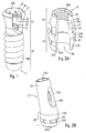
- ein Implantat mit einem Innenachtkant im lmplantatkopf als Teilschnitt;
- Figur 2A:
- ein gerades Abutment erster Ausführungsform mit einem Aussenachtkant an der Wurzelpartie und einem Aussenachtkant an der Halspartie als Teilschnitt;
- Figur 2B:
- ein abgewinkeltes Abutment zweiter Ausführungsform mit einem Aussenachtkant an der Wurzelpartie, einer konischen Halspartie und einer lateralen Öffnung;
- Figur-2C:
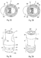
- das Abutment-gemäss-Figur 2B von unten als Perspektivansicht;
- Figur 2D:
- das Abutment gemäss Figur 2B mit Versetzung des Aussenachtkants an der Wurzelpartie um 22,5° von unten als Perspektivansicht;
- Figur 2E:
- ein gerades Abutment dritter Ausführungsform mit einem Aussenachtkant an der Wurzelpartie, einer konischen Halspartie und zwei lateralen Öffnungen;
- Figur 3A:
- eine Basisschraube erster Ausführungsform mit konisch-tailliertem Hals;
- Figur 3B:
- die Basisschraube zweiter Ausführungsform mit konisch-zylindrischem Hals;
- Figur 4A:
- einen Stützring ersterAusführungsform;
- Figur 4B:
- einen Stützring zweiter Ausführungsform mit einem durchgehenden Vertikalschlitz;
- Figur 4C:
- einen Stützring dritterAusführungsform mit vier Dehnungsschlitzen;
- Figur 4D:
- einen Stützring vierter Ausführungsform mit Innengewinde und durchgehendem Vertikalschlitz;
- Figur 5A:
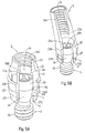
- das Abutment gemäss Figur 2A, den Stützring gemäss Figur 4A und die Basisschraube gemäss Figur 3B in Kombination als Teilschnitt;
- Figur 5B:
- das Abutment gemäss Figur 2B, den Stützring gemäss Figur 4A und die Basisschraube gemäss Figur 3B in Kombination als Teilschnitt;
- Figur 5C:
- das Abutment gemäss Figur 2E, den Stützring gemäss Figur 4A und die Basisschraube gemäss Figur 3B in Kombination als Teilschnitt;
- Figur 6A:
- eine Verbindungsanordnung mit dem Implantat gemäss Figur 1, dem Abutment gemäss Figur 2A, dem Stützring gemäss Figur 4A und der Basisschraube gemäss Figur 3B als Teilschnitt;
- Figur 6B:
- die Verbindungsanordnung gemäss Figur 6A mit aufgesetzter Goldkappe und Okklusalschraube als Teilschnitt;
- Figur 6C:
- eine Verbindungsanordnung mit dem Implantat gemäss Figur 1, dem Abutment gemäss Figur 2E, dem Stützring gemäss Figur 4A, der Basisschraube gemäss Figur 3B und einer verschraubten Transversalkappe als Teilschnitt;
- Figur 7A:
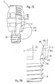
- das gerade Abutment gemäss Figur 2A mit axial verlängerter Unterkante, eingesetztem Stützring gemäss Figur 4A und eingesetzter Basisschraube gemäss Figur 3A als Teilschnitt;
- Figur 7B:
- das Detail X aus Figur 7A in der Vergrösserung;
- Figur 7C:
- die Anordnung gemäss Figur 7A mit den Stützring fixierender, umgebogener Unterkante; und
- Figur 7D:
- das Detail Y aus Figur 7C in der Vergrösserung.
- Anhand der beiliegenden Zeichnungen erfolgt nachstehend die detaillierte Beschreibung von Ausführungsbeispielen zur erfindungsgemässen Verbindungsanordnung.
- Für die gesamte weitere Beschreibung gilt folgende Festlegung. Sind in einer Figur zum Zweck zeichnerischer Eindeutigkeit Bezugsziffern enthalten, aber im unmittelbar zugehörigen Beschreibungstext nicht erläutert, so wird auf deren Erwähnung in vorangehenden Figurenbeschreibungen Bezug genommen. Im Interesse der Übersichtlichkeit wird auf die wiederholte Bezeichnung von Bauteilen in nachfolgenden Figuren zumeist verzichtet, sofern zeichnerisch eindeutig erkennbar ist, dass es sich um "wiederkehrende" Bauteile handelt.
- Das in der Verbindungsanordnung verwendete Implantat 1 ist von an sich bekanntem Aufbau. Das Implantat 1 besitzt oben den Implantatkopf 10 und unten die Schaftpartie 19, wobei der Implantatkopf 10 mit der radial umlaufenden Implantatschulter 11 zuoberst abschliesst und an der Schaftpartie 19 je nach Implantattyp ein Aussengewinde 190 vorhanden sein kann. Die Impfantatschulter 11 umgibt die Mündung der sich axial abwärts konisch verengenden Aufnahmebohrung 12. Am Bohrungsgrund 13 geht die Aufnahmebohrung 12 in eine koaxiale, im Durchmesser reduzierte Innengewindebohrung 14 über, die sich bis in die Schaftpartie 19 hinein erstreckt.
- Innerhalb der Aufnahmebohrung 12 ist als nicht-rotationssymmetrische Aufnahmekontur hier beispielhaft ein radial umlaufender innenachtkant 15 ausgebildet. Unterhalb des Innenachtkants 15 liegt eine zirkuläre Ringnut 16, die sich zur spanenden Herstellung des Innenachtkants 15 empfiehlt. Der Innenachtkant 15 läuft nach oben hin in parabelförmigen Spitzen aus. Vorteilhaft liegt der Innenachtkant 15 derart innerhalb der Aufnahmebohrung 12, dass sowohl über diesem als auch darunter unterbrechungslose, zueinander fluchtende Konusabschnitte 120,121 der Aufnahmebohrung 12 erhalten bleiben. Das dargestellte Implantat 1 ist ein Vollschraubenimplantat; die Verbindungsanordnung kann jedoch gleichermassen mit einem Hohischrauben-, Hohlkörper- und Vollkörperimplantat in gerader oder abgewinkelter Version aufgebaut werden.
- Dieses gerade Abutment 2 erster Ausführungsform weist oben die Halspartie 20 und die sich nach unten anschliessende, in Abschnitten konische Wurzelpartie 29 auf. Letztere ist zum Einsetzen in die Aufnahmebohrung 12 des Implantats 1 bestimmt, während die Halspartie 20 die Implantatschulter 11 überragt. Die Halspartie 20 gliedert sich in drei Segmente, nämlich das sich unmittelbar über der Wurzelpartie 29 anschliessende Vielkantsegment 21 - hier ein Aussenachtkant -, das zuoberst vorhandene zylindrische Führungssegment 23 und das zwischen dem Vielkantsegment 21 und dem Führungssegment 23 liegende Konussegment 22. Das Vielkantsegment 21 ist zur reproduzierbaren Positionierung bei der Abdrucknahme und der Modellherstellung sowie als eventuelle Rotationssicherung der aufgesetzten Suprastruktur nützlich. Das Führungssegment 23 trägt zur Zentrierung und Führung der aufgesetzten Kronenkappe bei.
- An der Wurzelpartie 29 befindet sich eine zur Aufnahmekontur 15 im Implantat 1 komplementäre Gegenkontur, folglich hier ein Aussenachtkant 28. Oberhalb des Aussenachtkants 28 liegt ein Konusabschnitt 270, welcher an das Vielkantsegment 21 angrenzt, und unterhalb des Aussenachtkants 28 liegt der Konusabschnitt 271, mit dem das Abutment 2 an der Unterkante 272 endet: Beide Konusabschnitte 270,271 fluchten zueinander, so dass im eingesetzten Zustand jeweils vom Implantat 1 und vom Abutment 2 die oberen und unteren Konusabschnitte 120,270;121,271 aneinander zu liegen kommen. Vorzugsweise fluchten die Planflächen des Vielkantsegments 21 und des Aussenachtkants 28 zueinander.
- Durch das Abutment 2 erstreckt sich ein Einlass 24, hier im Form eines Axialdurchgangs, welcher sich in mehrere Zonen aufgliedert. Im Bereich des Führungs- und des Konussegments 23,22 ist ein Innengewinde 240 zur Aufnahme einer Okklusalschraube vorgesehen. Das Innengewinde 240 hat vorzugsweise den gleichen Durchmesser wie die Innengewindebohrung 14 im Implantat 1. Unterhalb des Innengewindes 240 liegt nach einer Schulterfläche 244 eine gegenüber dem Innengewinde 240 im Durchmesser erweiterte Kopfzone 241, welcher sich etwa über den Bereich von Vielkantsegment 21 und oberem Konusabschnitt 270 erstreckt. Die Kopfzone 241 geht mit einer zirkulären Schulterfläche 242 abwärts zur Mündung des Einlasses 24 in eine radiale Erweiterung 243 über. Die Erweiterung 243 weist einen grösseren Innendurchmesser als die Kopfzone 241 auf und ist zur Aufnahme eines Stützrings vorgesehen, dessen Einsetztiefe von der Schulterfläche 242 begrenzt wird.
- Das dargestellte Abutment 2 zweiter Ausführungsform besitzt gegenüber der ersten Ausführungsform eine abgewandelte, schräg an die unveränderte Wurzelpartie 29 ansetzende Halspartie 20, die sich als Ganzes zum freien, oberen Ende hin konisch verjüngt. Unten endet das Abutment 2 mit der Unterkante 272. Der Einlass 24 ist jetzt abgewinkelt, wobei wiederum intern das innengewinde 240 und - allesamt nicht sichtbar - die Kopfzone 241, die Schulterfläche 242 und die Erweiterung 243 vorhanden sind. Für den Eingriff eines Schraubwerkzeugs besitzt das Abutment 2 an der Halspartie 20 eine senkrecht orientierte Lateralöffnung 200. Der Aussenachtkant 28 an der Wurzelpartie 29 ist so ausgerichtet, dass zwei zueinander parallele Planflächen 280 des Aussenachtkants 28 senkrecht zur Neigung der Halspartie 20 ausgerichtet sind. Innerhalb eines Systems kann man zur besseren Anpassung an die jeweiligen anatomischen Gegebenheiten verschiedene Neigungen - z.B. 15° und 20° - vorsehen.
- In einer Variante des abgewinkelten Abutments 2 weist der Aussenachtkant 28 an der Wurzelpartie 29 eine Versetzung um 22,5° auf, so dass alle Planflächen 280 des Aussenachtkants 28 peripher zur Neigung der Halspartie 20 ausgerichtet sind. Die durch den Schnittpunkt zweier benachbarter Planflächen 280 gebildeten Spitzen liegen nun senkrecht zur Neigung der Halspartie 20. Mit den beiden Varianten gemäss den Figuren 2C und 2D stehen dann 16 Drehstellungen mit jeweils 22,5° Versetzung zur Verfügung.
- Das Abutment 2 dritter Ausführungsform besitzt eine an die unveränderte Wurzelpartie 29 gerade ansetzende konische Halspartie 20, die vorteilhaft zuoberst mit einem zylindrischen Führungssegment 23 abschliesst. An der Halspartie 20 sind zwei Lateralöffnungen 201 für die transversale Verschraubung mit einer aufgesetzten Kronenkappe vorhanden. Vorzugsweise sind die Lateralöffnungen 201 von der Flucht um 22,5° zueinander versetzt. Damit stehen 16 Drehstellungen einer auf das Implantat 1 und das Abutment 2 aufgesetzten Transversalkappe 7 zur Verfügung (s. Figur 6C). So wird eine bessere Anpassung an die vorgefundenen anatomischen Verhältnisse möglich, was besonders beim Ersatz eines Einzelzahns relevant ist.
- Für den Aufbau der erfindungsgemässen Verbindungsanordnung auf dem Implantat 1 benötigt man alternativ eine der zuvor beschriebenen Ausführungsformen des Abutments 2 - die Halspartie 20 könnte weitere Modifikationen aufweisen - und eine Basisschraube 3. Die Basisschraube 3 besteht abwärts betrachtet aus dem im Prinzip zylindrischen Schraubenkopf 30, dem daran anschliessenden konisch-taillierten Schraubenhals 31 und dem unteren Gewindeschaft 32. An der Oberseite des Schraubenkopfes 30 ist eine Eingriffskontur 300 für das Schraubwerkzeug vorgesehen. Der oben konische Schraubenhals 31 setzt absatzlos unten an den Schraubenkopf 30 mit einer sich zunächst verjüngenden Schrägfläche 310 an und geht dann tailliert, sich verdickend in den Gewindeschaft 32 über. Die harmonischen Übergänge zwischen Schraubenkopf 30, Schraubenhals 31 und Gewindeschaft 32 dienen der Verminderung von Spannungskonzentrationen. Im Interesse einer möglichst geringen Schraubenlängskraft der Basisschraube 3 sollte die Oberfläche des Gewindeschafts 32 relativ glatt und zur Erzielung eines hohen Lösemoments die Schrägfläche 310 hingegen rauher beschaffen sein.
- Der Unterschied zur oben beschriebenen Basisschraube 3 erster Ausführungsform liegt lediglich in der Geometrie des Schraubenhalses 31, weicher hier bei der zweiten Ausführungsform konisch-zylindrisch ist. Die Schrägfläche 310 setzt wiederum ohne einen Absatz unten an den Schraubenkopf 30 an. Vorteilhaft sind die Übergänge gerundet.
- In der ersten, einfachsten Form (Figur 4A) besteht der Stützring 4 aus einem rohrförmigen Hülsenstück und besitzt an seiner Oberkante 40 eine interne Anschrägung 400 zur Auflage für die Schrägfläche 310 der Basisschraube 3. Vorzugsweise ist auch die Unterkante 41 mit einer Anschrägung 400 versehen, so dass bei der Fertigung der Stützring 4 in das Abutment 2 eingesetzt werden kann, ohne darauf achten zu müssen, mit welcher Kante 40,41 voran man den Stützring 4 einführt. Bei der zweiten Ausführungsform (Figur 4B) weist der Stützring 4 einen durchgehenden Vertikalschlitz 42 auf und ist somit offen. In der dritten Ausführungsform (Figur 4C) sind mehrere, systematisch verteilte Dehnungsschlitze 43 vorgesehen. Diese Dehnungs-schlitze 43 laufen von der Oberkante 40 vertikal auf die Unterkante 41 zu und erstrecken sich partiell über die Höhe des Stützrings 4. Die Anschrägung 400 ist folglich durch die Dehnungsschlitze 43 mehrfach unterbrochen. Bei der vierten Ausführungsform (Figur 4D) ist der Stützring 4 durch einen Vertikalschlitz 42 offen und ein Innengewinde 44 zieht sich durch den Stützring 4. Das Innengewinde 44 ist zum Gewinde am Gewindeschaft 32 passend, so dass sich der Stützring 4 bei der Vormontage auf die Basisschraube 2 über den Gewindeschaft 32 aufschrauben lässt. Diese Form des Stützrings 4 ist in der Herstellung aufwendiger, man erhält damit aber für die aufsitzende Basisschraube 2 eine verbreiterte Anschrägung 400.
- Als Baueinheit ist in ein gerades Abutment 2 mit Vielkantsegment 21, Konussegment 22 und Führungssegement 23 eine Basisschraube 3 eingesetzt, die von einem Stützring 4 gehalten wird. Bei der Montage dieser Baueinheit bieten sich zwei weitgehend ähnliche Arbeitsverfahren an.
-
- 1. Schritt:
- Einführen des Schraubenkopfes 30 der Basisschraube 3 von unten in den Einlass 24 des Abutments 2, so dass der Schraubenkopf 30 innerhalb der Kopfzone 241 zu liegen kommt.
- 2. Schritt:
- Führen des Stützrings 4 über den Gewindeschaft 32 und Einsetzen des Stützrings 4 in die Erweiterung 243 im Abutment 2. Der Stützring 4 und die Erweiterung 243 bilden zusammen im oberen Abschnitt einen Presssitz.
- 3. Schritt:
- Fixieren des in der Erweiterung 243 sitzenden Stützrings 4 durch Einkleben oder Einzementieren an der Erweiterung 243 oder Verschweissen an seiner Unterkante 41 mit der Unterkante 272 des Abutments 2. Die Schrägfläche 310 der Basisschraube 3 liegt auf der internen Anschrägung 400 im Stützring 4 auf.
-
- 1. Schritt:
- Führen des Stützrings 4 über den Gewindeschaft 32 der Basisschraube 3
- 2. Schritt:
- Einführen des Schraubenkopfes 30 der Basisschraube 3 von unten in den Einlass 24 des Abutments 2 und Einsetzen des Stützrings 4 in die Erweiterung 243 im Abutment 2.
- 3. Schritt:
- Fixieren des in der Erweiterung 243 sitzenden Stützrings 4.
- In dieser vormontierten Kombination von Abutment 2 und durch den Stützring 4 gehaltenen Basisschraube 3 kann die Baueinheit in den Vertrieb gelangen.
- Auf gleiche Weise stellt man eine Baueinheit aus einem abgewinkelten Abutment 2 mit der Lateralöffnung 200 bzw. einem geraden Abutment 2 für Transversalverschraubung mit den Lateralöffnungen 201 und der von Stützringen 4 gehaltenen Basisschrauben 3 her.
- Bei der komplettierten Verbindungsanordnung sitzt die Wurzelpartie 29 des Abutments 2 in der Aufnahmebohrung 12 des Implantats 1, während die Halspartie 20 des Abutments 2 die Implantatschulter 11 überragt. Die Basisschraube 3 ist mit ihrem Gewindeschaft 32 in die Innengewindebohrung 14 des Implantats 1 eingeschraubt und die Schrägfläche 310 der Basisschraube 3 drückt auf die Anschrägung 400 des fest im Abutment 2 sitzenden Stützrings 4. Durch die auf den Stützring 4 über die Schrägfläche 310 und die Anschrägung 400 einwirkenden Kräfte werden wesentliche Kraftkomponenten quer auf den Stützring 4 bzw. das Abutment 2 geleitet, so dass die Befestigung des Stützrings 4 weniger auf axiales Herausdrücken beansprucht wird. Dies ist insbesondere bedeutsam, wenn die Fixierung des Stützrings 4 im Abutment 2 durch Verschweissen seiner Unterkante 41 mit der Unterkante 272 des Abutments 2 realisiert wird. Auf diese Weise entlastet man die Schweissnaht von den wirkenden Axialkräften. Die Schulterfläche 244 ist die Kopfzone 241 so begrenzend positioniert, dass beim Herausdrehen der Basisschraube 3 deren Schraubenkopf 30 mit seiner oberen Stirnfläche an der Schulterfläche 244 ansteht, bevor der Gewindeschaft 32 der Basisschraube 3 gänzlich aus dem Innengewinde 14 im Implantat 1 ausrastet. Hierdurch wird bei weiterem Herausdrehen der Basisschraube 3 das Abutment 2 aus den Konusabschnitten 120,121 im Implantat 1 ausgestossen.
- Hier ist die Verbindungsanordnung gemäss der vorherigen Figur mit einer auf das Abutment 2 aufgesetzten, an sich bekannten hülsenförmigen Kronenkappe 5 ergänzt, welche von einer in das Innengewinde 240 im Abutment 2 eingreifenden herkömmlichen Okklusalschraube 6 gehalten wird. Okklusalschraube 6 und Basisschraube 2 sind von gleicher Querschnittsdimension. Der Schraubenkopf 60 der Okklusalschraube 6 liegt in einem Schraubensitz 50, welcher sich oben intern in der Kronenkappe 5 befindet. Zum Abstützen auf der Implantatschulter 11 weist die Kronenkappe 5 einen zur Implantatschulter 11 komplementären flanschartigen Rand 51 auf.
- Diese Verbindungsanordnung umfasst ein Implantat 1, ein Abutment 2 und eine auf das Abutment 2 aufgesetzte an sich bekannte Transversalkappe 7, die mittels einer herkömmlichen Klemmschraube 8 transversal mit dem Abutment 2 verschraubt ist. Die Wurzelpartie 29 des Abutments 2 sitzt wiederum in der Aufnahmebohrung 12 des Implantats 1 und die Halspartie 20 des Abutments 2 überragt die Implantatschulter 11. Der Gewindeschaft 32 der Basisschraube 3 greift in die Innengewindebohrung 14 des Implantats 1 ein, wobei die Basisschraube 3 in vorbeschriebener Weise die Anschrägung 400 des im Abutment 2 sitzenden Stützrings 4 drückt. An der Transversalkappe 7 befindet sich zuunterst eine konische Auflagefläche 71 sowie eine seitlich wegragende Nase 70 mit einem transversalen Gewindeloch 72, in das eine Klemmschraube 8 eingedreht ist. Die Klemmschraube 8 ist auf eine der beiden Lateralöffnungen 201 gerichtet, so dass die Spitze 80 der Klemmschraube in die Lateralöffnung 201 hineinragt, sich oben gegen die Lateralöffnungen 201 abstützt und hierdurch die Transversalkappe 7 mit der Auflagefläche 71 auf die Implantatschulter 11 drückt.
- Hier ist eine weitere Ausführungsform für die Fixierung des in das gerade Abutment 2 eingesetzten Stützrings 4, auf dessen Anschrägung 400 die Schrägfläche 310 des Schraubenhalses 31 der Basisschraube 3 aufsitzt, gezeigt. Der Schraubenkopf 30 findet wiederum in der internen Kopfzone 241 im Abutment 2 Platz. Der zunächst noch nicht fixierte Stützring 4 liegt in der Erweiterung 243 innerhalb des Einlasses 24. Das Abutment 2 ist mit einer nach axial tiefer liegenden Unterkante 272' versehen, welche als Biegezone 273' die Unterkante 41 des insoweit positionierten Stützrings 4 in Abwärtsrichtung nach apikal überragt. Hinsichtlich der beiden alternativen Arbeitsverfahren, zum 1. und 2. Arbeitsschritt der Vormontage von Basisschraube 3 und Stützring 4 wird auf die Beschreibung zur Figur 5A verwiesen.
- Zur Begünstigung des Fliessverhaltens der Biegezone 273' beim Umbiegen und zur Erzielung einer optimalen Konturierung nach dem Umbiegen weist die Biegezone 273' eine äussere, radial umlaufende Verschmälerung 274' gegenüber der über der Verschmälerung 274' liegenden Wandung des Abutment 2 auf. Der Übergang in die Verschmälerung 274' ist durch eine konkave Krümmung 275' gebildet und die Unterkante 272' besitzt eine nach innen gewandte, sich nach apikal öffnende Konusfläche 276'.
- Bei der gemäss den Figuren 7A und 7B beschaffenen und vormontierten Anordnung wird zur dauerhaften Fixierung des Stützrings 4 die verlängerte Unterkante 272' nach innen gewandt, d.h. in Richtung des Schraubenhalses 31 umgebogen. Nach dem Umbiegen unterfasst die verformte Biegezone 273' des Abutments 2 die Unterkante 41 des Stützrings 4, so dass dieser jetzt in der Erweiterung 243 sitzend fixiert ist. Die Verschmälerung 274' der Biegezone 273' ergibt jetzt eine harmonisch den Stützring 4 unterlaufende Rundung und die vorherige Konusfläche 276' eine sich axial erstreckende Kante. Die Basisschraube 3 sitzt auf dem fixierten Stützring 4 auf, d.h. durch die Konfiguration der Schrägfläche 310 am Schraubenhals, welche bei angezogener Basisschraube 3 auf die Anschrägung 400 an der Oberkante 40 des Stützrings 4 presst, wird die Kraft im wesentlichen lateral in das Abutment 2 geleitet. In verhältnismässig geringem Masse wirken verbleibende axiale Kraftkomponenten auf die umgebogene Unterkante 272'.
- Bei dieser Ausführungsform der Verbindungsanordnung erübrigen sich die Apparatur für das Laserschweissen sowie der entsprechende spezifische Prüfaufwand und können durch eine mechanische Umformvorrichtung mit der adäquaten Gütekontrolle ersetzt werden.
- Zu den vorbeschriebenen Ausführungsbeispielen sind weitere konstruktive Modifikationen realisierbar. Hier ausdrücklich erwähnt seien noch:
- Die Aufnahmebohrung 12 im Implantat 1 könnte zylindrischer Form sein. Der Innenvielkant 15 ist verzichtbar und seine Positionierung innerhalb der Aufnahmebohrung 12 frei wählbar.
- Das Abutment 2 muss grundsätzlich eine zur Aufnahmebohrung 12 des Implantats 1 komplementäre Wurzelpartie 29 besitzen. Weist das Implantat 1 einen Innenachtkant 15 auf, so sind darin Abutments 2 mit und ohne Aussenvielkant 28 einsetzbar.
- Die Aussenkontur der Halspartie 20 des Abutments 2 kann völlig konisch oder völlig zylindrisch sein sowie Kombinationen konischer und zylindrischer Segmente aufweisen.
- Das Vielkantsegment 21 am Abutment 2 könnte durch eine andere nicht-rotationssymmetrische Aussenkontur ersetzt werden, welche zuoberst des Abutments 2 oder zwischen zwei Segmenten der Halspartie 20 liegen kann. In weiteren Alternativen könnte sich die nicht-rotationssymmetrische Aussenkontur - z.B. als Abflachung - über mehrere Segmente der Halspartie 20 oder über die gesamte Halspartie 20 erstrecken.
- Das Innengewinde 240 im Abutment 2 könnte auch einen gegenüber dem Innengewinde 14 im Implantat 1 kleineren oder geringfügig grösseren Durchmesser aufweisen.
- Es versteht sich für den Fachmann, dass die Innenkontur der Kronenkappe 5 und der Transversalkappe 7 an eine modifizierte Aussenkontur des Abutments 2 und der Implantatschulter 11 angepasst sein muss.
Claims (34)
- Verbindungsanordnung umfassend ein Dentalimplantat (1) und ein darauf zu fixierendes Abutment (2), wobei:a) das Implantat (1) einen Implantatkopf (10) und eine sich nach unten erstreckende Schaftpartie (19) aufweist;b) im Implantatkopf (10) eine Aufnahmebohrung (12) vorgesehen ist, die oben von einer Implantatschulter (11) umgeben mündet und unten an einem Bohrungsgrund (13) sacklochförmig endet, von welchem sich eine axiale, abwärts weisende Innengewindebohrung (14) erstreckt;c) das Abutment (2) eine obere Halspartie (20) sowie eine untere Wurzelpartie (29) besitzt, die an einer Unterkante (272) endet, und die Halspartie (20) aus dem Implantat (1) herausragt, während die Wurzelpartie (29) in der Aufnahmebohrung (12) steckt;d) eine das Abutment (2) mit dem Implantat (1) verbindende Basisschraube (3) vorgesehen ist, deren Schraubenkopf (30) im Abutment (2) sitzt, und deren Gewindeschaft (32) in die Innengewindebohrung (14) eingreift;e) das Abutment (2) einen an der Unterkante (272) beginnenden Einlass (24) aufweist, in dem ein Stützring (4) angeordnet ist, durch den die Basisschraube (3) ragt; dadurch gekennzeichnet, dassf) der Stützring (4) fest im Einlass (24) eingesetzt ist,g) vor dem Einsetzen des Stützrings (4) die Basisschraube (3) mit dem Schraubenkopf (30) voran, von seiten der Wurzelpartie (29), in den Einlass (24) einführbar ist; undh) die Basisschraube (3) im Abutment (2) gehalten auf dem Stützring (4) aufsitzt.
- Verbindungsanordnung nach Anspruch 1, dadurch gekennzeichnet, dassa) der Stützring (4) eine Oberkante (40) und eine Unterkante (41) aufweist; undb) die Unterkante (41) des Stützrings (4) mit der Unterkante (272) des Abutments (2) verschweisst sind.
- Verbindungsanordnung nach Anspruch 1, dadurch gekennzeichnet, dassa) der Stützring (4) eine Oberkante (40) und eine Unterkante (41) aufweist;b) das Abutment (2) eine axial unterhalb der Unterkante (41) des eingesetzten Stützring (4), sich nach apikal erstreckende Biegezone (273') besitzt, die zuunterst mit einer Unterkante (272') abschliesst; undc) nach erfolgtem Umbiegen diese Biegezone (273') die Unterkante (41) des Stützrings (4) umfasst und unterfasst.
- Verbindungsanordnung nach Anspruch 3, dadurch gekennzeichnet, dass zur Begünstigung des Fliessverhaltens der Biegezone (273') beim Umbiegen und zur Erzielung einer optimalen Konturierung nach dem Umbiegena) die Biegezone (273') eine äussere, radial umlaufende Verschmälerung (274') gegenüber der über der Verschmälerung (274') liegenden Wandung des Abutment (2) aufweist;b) der Übergang in die Verschmälerung (274') durch eine konkave Krümmung (275') gebildet ist; undc) die Unterkante (272') eine nach innen gewandte, sich nach apikal öffnende Konusfläche (276') besitzt.
- Verbindungsanordnung nach einem der Ansprüche 1 bis 4,
dadurch gekennzeichnet, dassa) der Stützring (4) an der Oberkante (40) eine radial umlaufende Anschrägung (400) besitzt, die sich zur Oberkante (40) hin konisch erweitert;b) an der Basisschraube (3) oberhalb des Gewindeschafts (32) eine sich abwärts verjüngende Schrägfläche (310) vorhanden ist;c) die Schrägfläche (310) der Basisschraube (3) auf der Anschrägung (400) des Stützrings (4) aufsitzt; undd) der Schraubenkopf (30) zum Ansetzen eines Schraubwerkzeugs eine Eingriffskontur (300) hat. - Verbindungsanordnung nach einem der Ansprüche 1 bis 4,
dadurch gekennzeichnet, dassa) die Halspartie (20) des Abutments (2) gerade oder abgewinkelt an dessen Wurzelpartie (29) ansetzt;b) bei einem geraden Abutment (2) der Einlass (24) durchgehend ist und den Eingriff in die Basisschraube (3) mit einem Schraubwerkzeug von seiten der Halspartie (20) erlaubt;c) bei einem abgewinkelten Abutment (2) für den Eingriff mit einem Schraubwerkzeug in die Basisschraube (3) die Halspartie (20) eine vertikal orientierte Lateralöffnung (200) aufweist;d) bei einem Abutment (2) für eine transversal aufschraubbare Suprakonstruktion (7) die Halspartie (20) zumindest eine transversal orientierte Lateralöffnung (201) aufweist. - Verbindungsanordnung nach Anspruch 1, dadurch gekennzeichnet, dassa) in der Halspartie (20) des Abutments (2) ein Innengewinde (240) zum Eingriff einer Okklusalschraube (6) zur Fixierung einer Suprakonstruktion (5) vorhanden ist; undb) die Innengewindebohrung (14) im Implantat (1) sowie das Innengewinde (240) in der Halspartie (20) des Abutments (2) von gleichem Durchmesser sind.
- Verbindungsanordnung nach Anspruch 1, dadurch gekennzeichnet, dassa) im Implantat (1) die Aufnahmebohrung (12) sich aufwärts konisch erweitert und eine nicht-rotationssymmetrische Aufnahmekontur (15) aufweist; undb) an der Wurzelpartie (29) des Abutments (2) zur konischen Aufnahmebohrung (12) und zur Aufnahmekontur (15) komplementär eine äusserliche Konuspartie (270,271) und eine äusserliche Gegenkontur (28) vorhanden sind.
- Verbindungsanordnung nach Anspruch 8, dadurch gekennzeichnet, dassa) am implantat (1) die nicht-rotationssymmetrische Aufnahmekontur (15) ein Innenvielkant (15) ist, über und unter dem je ein unterbrechungsloser Konusabschnitt (120,121) vorhanden ist, wobei beide Konusabschnitte (120,121) zueinander fluchten; undb) am Abutment (2) die Gegenkontur (28) ein Aussenvielkant (28) ist, welcher die Konuspartie (270,271) in einen darüber und einen darunter liegenden Konusabschnitt (270,271) teilt, die beide zueinander fluchten.
- Verbindungsanordnung nach Anspruch 5, dadurch gekennzeichnet, dass der Stützring (4)a) auch an Unterkante (41) eine radial umlaufende Anschrägung (400) besitzt, die sich zur Unterkante (41) hin konisch erweitert, wodurch der Stützring (4) an Ober- und Unterkante (40,41) gleich ausgebildet ist; undb) mittels eines durchgehenden Vertikalschlitzes (42) offen gestaltet sein kann oder partiell eingeschnittene Dehnungsschlitze (43) aufweist.
- Verbindungsanordnung , nach _Anspruch 5 oder 10, dadurch gekennzeichnet, dass der Stützring (4) zur Verbreiterung der Anschrägung (400) ein Innengewinde (44) aufweist, welches zum Gewindeschaft (32) der Basisschraube (3) komplementär ist und ein Aufschrauben des Stützrings (4) über den Gewindeschaft (32) erlaubt.
- Verbindungsanordnung nach Anspruch 1 oder 5, dadurch gekennzeichnet, dass die Basisschraube (3)a) zwischen ihrem Schraubenkopf (30) und Gewindeschaft (32) ein Schraubenhals (31) liegt;b) sich die Schrägfläche (310) am Schraubenhals (31) nahe dem Schraubenkopf (30) befindet;c) der Schraubenhals (31) konisch-tailliert oder konisch-zylindrisch ist, wobei sich der Schraubenhals (31) hin zum Schraubenkopf (30) konisch erweitert; undd) die Schrägfläche (310) eine grössere Rauhigkeit besitzt als der Gewindeschaft (32), um innerhalb der Verbindungsanordnung für die Basisschraube (3) ein grosses Lösemoment zu erreichen.
- Verbindungsanordnung nach einem der Ansprüche 1, bis 12, dadurch gekennzeichnet, dass das Abutment (2)a) im Einlass (24) eine Erweiterung (243) aufweist, die an der Unterkante (272) beginnt und sich intern im Abutment (2) adäquat zur Höhe des Stützrings (4) aufwärts bis zu einer Schulterfläche (242) erstreckt;b) die Erweiterung (243) einen grösseren lichten Durchmesser besitzt als die darüber liegende Kopfzone (241), die zur Aufnahme des Schraubenkopfes (30) der eingesetzten Basisschraube (3) bestimmt ist;c) die Erweiterung (243) zusammen mit dem Stützring (4), vorzugsweise im oberen Abschnitt, nach koronal, einen Presssitz bildet;d) die Kopfzone (241) einen grösseren lichten Durchmesser besitzt als der darüber verbleibende Bereich des Einlasses (24); unde) die Kopfzone (241) nach oben an einer einengenden Schulterfläche (244) endet, welche definiert positioniert ist, wodurch beim Herausdrehen der Basisschraube (3) deren Schraubenkopf (30) mit seiner oberen Stirnfläche an der Schulterfläche (244) ansteht, bevor der Gewindeschaft (32) der Basisschraube (3) gänzlich aus dem Innengewinde (14) im Implantat (1) ausrastet, und bei weiterem Herausdrehen der Basisschraube (3) das Abutment (2) aus den Konusabschnitten (120,121) im Implantat (1) ausgestossen wird.
- Verbindungsanordnung nach den Ansprüchen 6 und 8, dadurch gekennzeichnet, dassa) im Implantat (1) die Aufnahmekontur (15) ein Innenachtkant (15) ist;b) an der Wurzelpartie (29) des Abutments (2) die komplementäre Gegenkontur (28) ein Aussenachtkant (28) mit acht Planflächen (280) ist;c) an einem Abutment (2) mit an die Wurzelpartie (29) abgewinkelt angesetzter Halspartie (20) der Aussenachtkant (28) so positioniert ist, dass entwederca) zwei sich parallel gegenüber liegende Planflächen (280) senkrecht zur Neigung der Halspartie (20) liegen; odercb) der Aussenachtkant (28) um 22,5° versetzt ist, wodurch die im Schnittpunkt zweier benachbarter Planflächen (280) gebildeten Kanten senkrecht zur Neigung der Halspartie (20) liegen.
- Verbindungsanordnung nach Anspruch 6, dadurch gekennzeichnet, dassa) bei einem Abutment (2) für eine transversal verschraubbare Suprakonstruktion (7) die Halspartie (20) eine erste und eine zweite transversal orientierte Lateralöffnung (201) aufweist; undb) die zweite Lateralöffnung (201) im Verhältnis zur ersten Lateralöffnung (201) von der Flucht um 22,5° zueinander versetzt ist.
- Verbindungsanordnung nach Anspruch 1, dadurch gekennzeichnet, dass an der Halspartie (20) des Abutments (2) ein äusserliches Vielkantsegment (21) vorhanden ist, dessen Planflächen vorzugsweise mit den Planflächen des Aussenachtkants (28) an der Wurzeipartie (29) fluchten.
- Verbindungsanordnung nach Anspruch 16, dadurch gekennzeichnet, dassa) das Vielkantsegment (21) ein an die Wurzelpartie (29) angrenzender Aussenachtkant (21) ist;b) oberhalb des Vielkantsegments (21) ein sich aufwärts verjüngendes Konussegment (22) liegt; undc) über dem Konussegment (22) ein abschliessendes zylindrisches Führungssegment (23) liegen kann.
- Abutment (2) mit Basisschraube (3) und Stützring (4) zum Fixieren auf einem Dentalimplantat (1), wobei:a) das Abutment (2) aufweist:aa) eine obere Halspartie (20); undab) eine untere Wurzelpartie (29), die an einer Unterkante (272) endet, und zum Einsetzen in eine im Implantat (1) vorhandene Aufnahmebohrung (12) bestimmt ist;ac) eine Unterkante (272), wo ein Einlass (24) beginnt;b) die Basisschraube (3) aufweist:ba) einen Schraubenkopf (30), der im Abutment (2) sitzt; undbb) einen Gewindeschaft (32), der zum Eingreifen in eine Innengewindebohrung (14) bestimmt ist, die im Implantat (1) vorhanden ist;c) der Stützring (4) im Einlass (24) angeordnet ist; undd) durch den Stützring (4) die Basisschraube (3) ragt, dadurch gekennzeichnet, dasse) der Stützring (4) fest im Einlass (24) eingesetzt ist,f) vor dem Einsetzen des Stützrings (4) die Basisschraube (3) mit dem Schraubenkopf (30) voran, von seiten der Wurzelpartie (29), in den Einlass (24) einführbar ist; undg) die Basisschraube (3) im Abutment (2) gehalten auf dem Stützring (4) aufsitzt.
- Abutment (2) nach Anspruch 18, dadurch gekennzeichnet, dassa) der Stützring (4) eine Oberkante (40) und eine Unterkante (41) aufweist; undb) die Unterkante (41) des Stützrings (4) mit der Unterkante (272) des Abutments (2) verschweisst ist.
- Abutment (2) nach Anspruch 18, dadurch gekennzeichnet, dassa) der Stützring (4) eine Oberkante (40) und eine Unterkante (41) aufweist;b) das Abutment (2) eine axial unterhalb der Unterkante (41) des eingesetzten Stützring (4), sich nach apikal erstreckende Biegezone (273') besitzt, die zuunterst mit einer Unterkante (272') abschliesst; undc) nach erfolgtem Umbiegen diese Biegezone (273') die Unterkante (41) des Stützrings (4) umfasst und unterfasst.
- Abutment (2) nach Anspruch 20, dadurch gekennzeichnet, dass zur Begünstigung des Fliessverhaltens der Biegezone (273') beim Umbiegen und zur Erzielung einer optimalen Konturierung nach dem Umbiegena) die Biegezone (273') eine äussere, radial umlaufende Verschmälerung (274') gegenüber der über der Verschmälerung (274') liegenden Wandung des Abutment (2) aufweist;b) der Übergang in die Verschmälerung (274') durch eine konkave Krümmung (275') gebildet ist; undc) die Unterkante (272') eine nach innen gewandte, sich nach apikal öffnende Konusfläche (276') besitzt.
- Abutment (2) nach Anspruch 18 bis 21, dadurch gekennzeichnet, dassa) der Stützring (4) an der Oberkante (40) eine radial umlaufende Anschrägung (400) besitzt, die sich zur Oberkante (40) hin konisch erweitert;b) an der Basisschraube (3) oberhalb des Gewindeschafts (32) eine sich abwärts verjüngende Schrägfläche (310) vorhanden ist;c) die Schrägfläche (310) der Basisschraube (3) auf der Anschrägung (400) des Stützrings (4) aufsitzt; undd) der Schraubenkopf (30) zum Ansetzen eines Schraubwerkzeugs eine Eingriffskontur (300) hat.
- Abutment (2) nach Anspruch 18 bis 22, dadurch gekennzeichnet, dassa) die Halspartie (20) des Abutments (2) gerade oder abgewinkelt an dessen Wurzelpartie (29) ansetzt;b) bei einem geraden Abutment (2) der Einlass (24) durchgehend ist und den Eingriff in die Basisschraube (3) mit einem Schraubwerkzeug von seiten der Halspartie (20) erlaubt;c) bei einem abgewinkelten Abutment (2) für den Eingriff mit einem Schraubwerkzeug in die Basisschraube (3) die Halspartie (20) eine vertikal orientierte Lateralöffnung (200) aufweist;d) bei einem Abutment (2) für eine transversal aufschraubbare Suprakonstruktion (7) die Halspartie (20) zumindest eine transversal orientierte Lateralöffnung (201) aufweist.
- Abutment (2) nach Anspruch 18, dadurch gekennzeichnet, dassa) in der Halspartie (20) des Abutments (2) ein Innengewinde (240) zum Eingriff einer Okklusalschraube (6) zur Fixierung einer Suprakonstruktion (5) vorhanden ist; undb) das Innengewinde (240) in der Halspartie (20) von gleichem Durchmesser ist wie die Innengewindebohrung (14) im Implantat (1).
- Abutment (2) nach Anspruch 18, dadurch gekennzeichnet, dassa) an der Wurzelpartie (29) des Abutments (2) eine äusserliche Konuspartie (270,271) und eine äusserliche Gegenkontur (28) vorhanden sind; wobeib) die Konuspartie (270,271) zu der im Implantat (1) sich aufwärts konisch erweiternden Aufnahmebohrung (12) komplementär ist; undc) die Gegenkontur (28) zu einer in der Aufnahmebohrung (12) vorgesehenen nicht-rotationssymmetrischen Aufnahmekontur (15) komplementär ist.
- Abutment (2) nach Anspruch 25, dadurch gekennzeichnet, dass die Gegenkontur (28) ein Aussenvielkant (28) ist, welche die Konuspartie (270,271) in einen darüber und einen darunter liegenden Konusabschnitt (270,271) teilt, wobei beide Konusabschnitte (270,271) zueinander fluchten.
- Abutment (2) nach Anspruch 22, dadurch gekennzeichnet, dass der Stützring (4)a) auch an Unterkante (41) eine radial umlaufende Anschrägung (400) besitzt, die sich zur Unterkante (41) hin konisch erweitert, wodurch der Stützring (4) an Ober- und Unterkante (40,41) gleich ausgebildet ist; undb) mittels eines durchgehenden Vertikalschlitzes (42) offen gestaltet sein kann oder partiell eingeschnittene Dehnungsschlitze (43) aufweist.
- Abutment (2) nach Anspruch 22 oder 27, dadurch gekennzeichnet, dass der Stützring (4) zur Verbreiterung der Anschrägung (400) ein Innengewinde (44) aufweist, welches zum Gewindeschaft (32) der Basisschraube (3) komplementär ist und ein Aufschrauben des Stützrings (4) über den Gewindeschaft (32) erlaubt.
- Abutment (2) nach Anspruch 18 oder 22, dadurch gekennzeichnet, dass die Basisschraube (3)a) zwischen ihrem Schraubenkopf (30) und Gewindeschaft (32) ein Schraubenhals (31) liegt;b) sich die Schrägfläche (310) am Schraubenhals (31) nahe dem Schraubenkopf (30) befindet;c) der Schraubenhals (31) konisch-tailliert oder konisch-zylindrisch ist, wobei sich der Schraubenhals (31) hin zum Schraubenkopf (30) konisch erweitert; undd) die Schrägfläche (310) eine grössere Rauhigkeit besitzt als der Gewindeschaft (32), um innerhalb der Verbindungsanordnung für die Basisschraube (3) ein grosses Lösemoment zu erreichen.
- Abutment (2) nach einem der Ansprüche 18 bis 29, dadurch gekennzeichnet, dass das Abutment (2)a) im Einlass (24) eine Erweiterung (243) aufweist, die an der Unterkante (272) beginnt und sich intern im Abutment (2) adäquat zur Höhe des Stützrings (4) aufwärts bis zu einer Schulterfläche (242) erstreckt;b) die Erweiterung (243) einen grösseren lichten Durchmesser besitzt als die darüber liegende Kopfzone (241), die zur Aufnahme des Schraubenkopfes (30) der eingesetzten Basisschraube (3) bestimmt ist;c) die Erweiterung (243) zusammen mit dem Stützring (4), vorzugsweise im oberen Abschnitt, nach koronal, einen Presssitz bildet;d) die Kopfzone (241) einen grösseren lichten Durchmesser besitzt als der darüber verbleibende Bereich des Einlasses (24); unde) die Kopfzone (241) nach oben an einer einengenden Schulterfläche (244) endet, welche definiert positioniert ist, wodurch beim Herausdrehen der Basisschraube (3) deren Schraubenkopf (30) mit seiner oberen Stirnfläche an der Schulterfläche (244) ansteht, bevor der Gewindeschaft (32) der Basisschraube (3) gänzlich aus dem Innengewinde (14) im Implantat (1) ausrastet, und bei weiterem Herausdrehen der Basisschraube (3) das Abutment (2) aus den Konusabschnitten (120,121) im Implantat (1) ausgestossen wird.
- Abutment (2) nach den Ansprüchen 23 und 25, dadurch gekennzeichnet, dassa) an der Wurzelpartie (29) des Abutments (2) die komplementäre Gegenkontur (28) ein Aussenachtkant (28) mit acht Planflächen (280) ist;b) an einem Abutment (2) mit an die Wurzelpartie (29) abgewinkelt angesetzter Halspartie (20) der Aussenachtkant (28) so positioniert ist, dass entwederba) zwei sich parallel gegenüber liegende Planflächen (280) senkrecht zur Neigung der Halspartie (20) liegen; oderbb) der Aussenachtkant (28) um 22,5° versetzt ist, wodurch die im Schnittpunkt zweier benachbarter Planflächen (280) gebildeten Kanten senkrecht zur Neigung der Halspartie (20) liegen.
- Abutment (2) nach Anspruch 23, dadurch gekennzeichnet, dassa) bei einem Abutment (2) für eine transversal verschraubbare Suprakonstruktion (7) die Halspartie (20) eine erste und eine zweite transversal orientierte Lateralöffnung (201) aufweist; undb) die zweite Lateralöffnung (201) im Verhältnis zur ersten Lateralöffnung (201) von der Flucht um 22,5° zueinander versetzt ist.
- Abutment (2) nach Anspruch 18, dadurch gekennzeichnet, dass an der Halspartie (20) des Abutments (2) ein äusserliches Vielkantsegment (21) vorhanden ist, dessen Planflächen vorzugsweise mit den Planflächen des Aussenachtkants (28) an der Wurzelpartie (29) fluchten.
- Abutment (2) nach Anspruch 33, dadurch gekennzeichnet dassa) das Vielkantsegment (21) ein an die Wurzelpartie (29) angrenzender Aussenachtkant (21) ist;b) oberhalb des Vielkantsegments (21) ein sich aufwärts verjüngendes Konussegment (22) liegt; undc) über dem Konussegment (22) ein abschliessendes zylindrisches Führungssegment (23) liegen kann.
Applications Claiming Priority (3)
| Application Number | Priority Date | Filing Date | Title |
|---|---|---|---|
| PCT/CH1998/000555 WO1999016293A2 (de) | 1998-12-28 | 1998-12-28 | Verbindungsanordnung zwischen einem dentalimplantat und einem abutment |
| WOPCT/CH98/00005 | 1998-12-28 | ||
| PCT/CH1999/000628 WO2000038588A1 (de) | 1998-12-28 | 1999-12-27 | Verbindungsanordnung zwischen einem dentalimplantat und einem abutment |
Publications (2)
| Publication Number | Publication Date |
|---|---|
| EP1139906A1 EP1139906A1 (de) | 2001-10-10 |
| EP1139906B1 true EP1139906B1 (de) | 2006-06-07 |
Family
ID=4551382
Family Applications (1)
| Application Number | Title | Priority Date | Filing Date |
|---|---|---|---|
| EP99962024A Expired - Lifetime EP1139906B1 (de) | 1998-12-28 | 1999-12-27 | Verbindungsanordnung zwischen einem dentalimplantat und einem abutment |
Country Status (9)
| Country | Link |
|---|---|
| EP (1) | EP1139906B1 (de) |
| JP (1) | JP3678653B2 (de) |
| AT (1) | ATE328545T1 (de) |
| AU (2) | AU1553599A (de) |
| BR (1) | BR9915812A (de) |
| CA (1) | CA2351434C (de) |
| DE (1) | DE59913530D1 (de) |
| ES (1) | ES2265695T3 (de) |
| WO (2) | WO1999016293A2 (de) |
Cited By (4)
| Publication number | Priority date | Publication date | Assignee | Title |
|---|---|---|---|---|
| CH702350A1 (de) * | 2009-12-11 | 2011-06-15 | Ceramics Solutions Ag | Dentalimplantat. |
| WO2012085039A1 (en) | 2010-12-23 | 2012-06-28 | Straumann Holding Ag | Dental implant and dental implant kit |
| US9095398B2 (en) | 2011-06-01 | 2015-08-04 | Straumann Holding Ag | Two-part dental component |
| US11602416B2 (en) | 2016-02-04 | 2023-03-14 | Holger Zipprich | Abutment, in particular for use with a dental implant inserted into the jaw bone of a patient, and method for producing the abutment |
Families Citing this family (24)
| Publication number | Priority date | Publication date | Assignee | Title |
|---|---|---|---|---|
| AU1553599A (en) * | 1998-12-28 | 1999-04-23 | Institut Straumann Ag | Connection arrangement between a dental implant and an abutment |
| AU6568601A (en) * | 2000-06-16 | 2001-12-24 | Gianni Nichinonni | Dental implant abutment |
| AUPQ817900A0 (en) * | 2000-06-16 | 2000-07-06 | Nichinonni, Gianni | Dental implant abutment |
| ITPS20030006A1 (it) * | 2003-03-13 | 2004-09-14 | Massimo Corigliano | Struttura di innesto di monconi di supporto di protesi endossee ad inserti ossei osteoconnessi, specie per applicazioni odontoiatriche. |
| FR2886838B1 (fr) * | 2005-06-10 | 2008-02-29 | Rech S Et De Fabrication S E R | Ensemble prothetique dentaire |
| WO2008071368A1 (de) | 2006-12-14 | 2008-06-19 | Friadent Gmbh | Anordnung zur insertion von implantaten |
| DE102006005705A1 (de) * | 2006-02-08 | 2007-08-16 | Ilja Beilin | Applikation einer konischen Verbindung in voller Länge mit internen Aussparungen für Instrumente und Schaffung einer biologischen Abdichtung für enossale Zahnimplantate |
| EP2036515B2 (de) | 2007-09-17 | 2021-12-08 | Straumann Holding AG | Verbindungsanordnung zwischen einem Dentalimplantat und einem Abutment |
| DE102008027007A1 (de) * | 2008-06-06 | 2009-12-10 | Ilja Beilin | Verwendung der internen Aussparungen des Zahnimplantats die für die Werkzeuge vorgesehen sind, für die wiederholte Positionierung des zweiteiligen Kopfteils in voller Länge der konischen Verbindung, mit Erhaltung der ununterbrochenen biologischen Abdichtung des Implantats |
| ES2340565B1 (es) * | 2008-06-20 | 2011-05-11 | Biotechnology Institute, I Mas D, S.L. | Elemento roscado que se conecta al agujero roscado de un implante dental. |
| JP5285021B2 (ja) * | 2009-09-02 | 2013-09-11 | 株式会社アルツロ | 人体インプラント構造 |
| ES2357204B1 (es) * | 2009-10-08 | 2012-03-06 | Ramón Farre Berga | Aditamiento para la confección de la estructura interna de prótesis dentales. |
| JP5749911B2 (ja) * | 2010-09-30 | 2015-07-15 | 株式会社ジーシー | 歯科用インプラント |
| EP2607722B1 (de) | 2011-12-22 | 2014-02-26 | Straumann Holding AG | Verbindungsschraube für ein Dentalimplantat |
| US9907628B2 (en) | 2013-10-17 | 2018-03-06 | Tosa Enterprise Co., Ltd. | Implants for an artificial tooth |
| JP5548298B1 (ja) * | 2013-10-17 | 2014-07-16 | 土佐エンタープライズ株式会社 | 歯科インプラントシステム |
| US10470851B2 (en) | 2013-12-24 | 2019-11-12 | Straumann Holding Ag | Self-retaining dental screw |
| BR102014021198B1 (pt) * | 2014-08-27 | 2021-08-03 | Lotario Thum | Aperfeiçoamento em implante dentário |
| EP3244825B1 (de) | 2015-09-30 | 2021-11-03 | Implant Direct Sybron International LLC | Dentale anordnung und verfahren zu dessen herstellung |
| SE539676C2 (en) * | 2016-11-08 | 2017-10-31 | Integrum Ab | Anchoring system for attaching a prosthesis to a human body |
| US11826224B2 (en) | 2017-04-03 | 2023-11-28 | Implant Direct Sybron International Llc | Multi-unit dental assembly with off-axis feature |
| EP3398553A1 (de) | 2017-05-02 | 2018-11-07 | Ophir Fromovich | Verbessertes zahnimplantatsystem |
| BR202020012753U2 (pt) * | 2020-06-22 | 2022-01-04 | José Ricardo Magnani Fortunato | Munhão angulado parafusado |
| DE102023136611A1 (de) | 2023-12-22 | 2025-06-26 | Bego Implant Systems Gmbh & Co. Kg | Mehrteiliger Zahnersatz mit Schraubverbindung |
Family Cites Families (4)
| Publication number | Priority date | Publication date | Assignee | Title |
|---|---|---|---|---|
| GB2199626B (en) | 1987-01-08 | 1991-09-04 | Core Vent Corp | Screw-type dental implant anchor |
| SE9203184D0 (sv) | 1992-10-28 | 1992-10-28 | Astra Ab | Dental implant |
| CA2232822A1 (en) | 1995-10-13 | 1997-04-24 | Vincenzo Grande | Connection arrangement between an implant and an abutment |
| AU1553599A (en) * | 1998-12-28 | 1999-04-23 | Institut Straumann Ag | Connection arrangement between a dental implant and an abutment |
-
1998
- 1998-12-28 AU AU15535/99A patent/AU1553599A/en not_active Abandoned
- 1998-12-28 WO PCT/CH1998/000555 patent/WO1999016293A2/de not_active Ceased
-
1999
- 1999-12-27 EP EP99962024A patent/EP1139906B1/de not_active Expired - Lifetime
- 1999-12-27 ES ES99962024T patent/ES2265695T3/es not_active Expired - Lifetime
- 1999-12-27 AT AT99962024T patent/ATE328545T1/de active
- 1999-12-27 JP JP2000590543A patent/JP3678653B2/ja not_active Expired - Lifetime
- 1999-12-27 CA CA002351434A patent/CA2351434C/en not_active Expired - Fee Related
- 1999-12-27 BR BR9915812-4A patent/BR9915812A/pt not_active IP Right Cessation
- 1999-12-27 AU AU18543/00A patent/AU749684B2/en not_active Ceased
- 1999-12-27 DE DE59913530T patent/DE59913530D1/de not_active Expired - Lifetime
- 1999-12-27 WO PCT/CH1999/000628 patent/WO2000038588A1/de not_active Ceased
Cited By (4)
| Publication number | Priority date | Publication date | Assignee | Title |
|---|---|---|---|---|
| CH702350A1 (de) * | 2009-12-11 | 2011-06-15 | Ceramics Solutions Ag | Dentalimplantat. |
| WO2012085039A1 (en) | 2010-12-23 | 2012-06-28 | Straumann Holding Ag | Dental implant and dental implant kit |
| US9095398B2 (en) | 2011-06-01 | 2015-08-04 | Straumann Holding Ag | Two-part dental component |
| US11602416B2 (en) | 2016-02-04 | 2023-03-14 | Holger Zipprich | Abutment, in particular for use with a dental implant inserted into the jaw bone of a patient, and method for producing the abutment |
Also Published As
| Publication number | Publication date |
|---|---|
| AU749684B2 (en) | 2002-07-04 |
| BR9915812A (pt) | 2001-10-30 |
| EP1139906A1 (de) | 2001-10-10 |
| AU1854300A (en) | 2000-07-31 |
| JP3678653B2 (ja) | 2005-08-03 |
| CA2351434C (en) | 2005-10-11 |
| DE59913530D1 (de) | 2006-07-20 |
| AU1553599A (en) | 1999-04-23 |
| ATE328545T1 (de) | 2006-06-15 |
| WO2000038588A1 (de) | 2000-07-06 |
| CA2351434A1 (en) | 2000-07-06 |
| HK1042033A1 (en) | 2002-08-02 |
| WO1999016293A2 (de) | 1999-04-08 |
| JP2002533155A (ja) | 2002-10-08 |
| ES2265695T3 (es) | 2007-02-16 |
| WO1999016293A3 (de) | 1999-10-28 |
Similar Documents
| Publication | Publication Date | Title |
|---|---|---|
| EP0801544B1 (de) | Verbindungsanordnung zwischen einem implantat und einem abutment | |
| WO1999016293A2 (de) | Verbindungsanordnung zwischen einem dentalimplantat und einem abutment | |
| EP0629384B1 (de) | Vorrichtung zur Befestigung eines künstlichen Zahnersatzes an einem Kieferknochen | |
| EP1100395B1 (de) | Vorrichtung zum halten und/oder bilden eines zahnersatzes | |
| DE69832794T2 (de) | Zahn implantatsysteme | |
| EP1444964B1 (de) | Support zum Halten und/oder Bilden eines Zahnersatzes | |
| EP1843717B1 (de) | Dentalimplantat | |
| DE68923787T2 (de) | Zahnanker mit gewinde. | |
| DE69117138T2 (de) | Wurzelstift mit aktivem und passivem Teil | |
| DE69833559T3 (de) | Implantat mit Gewinde womit eine sichere Verankerung im Knochen erzielt wird | |
| DE69425880T2 (de) | Sicherungselement | |
| EP1014883A1 (de) | Dentalimplantat sowie vorrichtung mit einem dentalimplantat | |
| EP0868889A1 (de) | Zahnimplantat | |
| EP0784456A1 (de) | Kieferimplantat | |
| EP2674127B1 (de) | Implantat | |
| WO1996029019A1 (de) | Verbindungsanordnung für implantat gestützten zahnersatz | |
| DE3249223T1 (de) | Zahnanker | |
| CH696800A5 (de) | Implantat zum Halten und /oder Bilden eines Zahnersatzes und verschiedene Zubehörteile zu einem Implantat. | |
| EP1704830A1 (de) | Implantatanalog | |
| DE20304755U1 (de) | Kieferimplantat, insbesondere ein einphasiges Dental (definitiv)-Implantat mit geradem und abgewinkeltem Pfostenverlauf | |
| CH684384A5 (de) | Implantat zur Befestigung eines künstlichen Zahnersatzes an einem Kieferknochen. | |
| WO2004037110A1 (de) | Enossales dentalimplantat und dentalimpantat-set | |
| WO1999039653A1 (de) | Enossales dentalimplantat mit selbst-schneidendem gewinde | |
| EP0896812A1 (de) | Implantateinsatz zum Fördern des Wachstums der Gingiva | |
| WO1998042273A1 (de) | Zahnimplantat |
Legal Events
| Date | Code | Title | Description |
|---|---|---|---|
| PUAI | Public reference made under article 153(3) epc to a published international application that has entered the european phase |
Free format text: ORIGINAL CODE: 0009012 |
|
| 17P | Request for examination filed |
Effective date: 20010323 |
|
| AK | Designated contracting states |
Kind code of ref document: A1 Designated state(s): AT BE CH CY DE DK ES FI FR GB GR IE IT LI LU MC NL PT SE |
|
| AX | Request for extension of the european patent |
Free format text: AL;LT;LV;MK;RO;SI |
|
| GRAP | Despatch of communication of intention to grant a patent |
Free format text: ORIGINAL CODE: EPIDOSNIGR1 |
|
| GRAS | Grant fee paid |
Free format text: ORIGINAL CODE: EPIDOSNIGR3 |
|
| GRAA | (expected) grant |
Free format text: ORIGINAL CODE: 0009210 |
|
| AK | Designated contracting states |
Kind code of ref document: B1 Designated state(s): AT BE CH CY DE DK ES FI FR GB GR IE IT LI LU MC NL PT SE |
|
| PG25 | Lapsed in a contracting state [announced via postgrant information from national office to epo] |
Ref country code: IE Free format text: LAPSE BECAUSE OF FAILURE TO SUBMIT A TRANSLATION OF THE DESCRIPTION OR TO PAY THE FEE WITHIN THE PRESCRIBED TIME-LIMIT Effective date: 20060607 Ref country code: FI Free format text: LAPSE BECAUSE OF FAILURE TO SUBMIT A TRANSLATION OF THE DESCRIPTION OR TO PAY THE FEE WITHIN THE PRESCRIBED TIME-LIMIT Effective date: 20060607 |
|
| REG | Reference to a national code |
Ref country code: GB Ref legal event code: FG4D Free format text: NOT ENGLISH |
|
| REG | Reference to a national code |
Ref country code: CH Ref legal event code: EP |
|
| GBT | Gb: translation of ep patent filed (gb section 77(6)(a)/1977) |
Effective date: 20060619 |
|
| REG | Reference to a national code |
Ref country code: IE Ref legal event code: FG4D Free format text: LANGUAGE OF EP DOCUMENT: GERMAN |
|
| REF | Corresponds to: |
Ref document number: 59913530 Country of ref document: DE Date of ref document: 20060720 Kind code of ref document: P |
|
| REG | Reference to a national code |
Ref country code: CH Ref legal event code: NV Representative=s name: MARK-PAT MODIANO S.A. |
|
| PG25 | Lapsed in a contracting state [announced via postgrant information from national office to epo] |
Ref country code: DK Free format text: LAPSE BECAUSE OF FAILURE TO SUBMIT A TRANSLATION OF THE DESCRIPTION OR TO PAY THE FEE WITHIN THE PRESCRIBED TIME-LIMIT Effective date: 20060907 |
|
| REG | Reference to a national code |
Ref country code: SE Ref legal event code: TRGR |
|
| PG25 | Lapsed in a contracting state [announced via postgrant information from national office to epo] |
Ref country code: PT Free format text: LAPSE BECAUSE OF FAILURE TO SUBMIT A TRANSLATION OF THE DESCRIPTION OR TO PAY THE FEE WITHIN THE PRESCRIBED TIME-LIMIT Effective date: 20061107 |
|
| REG | Reference to a national code |
Ref country code: HK Ref legal event code: GR Ref document number: 1042033 Country of ref document: HK |
|
| ET | Fr: translation filed | ||
| PG25 | Lapsed in a contracting state [announced via postgrant information from national office to epo] |
Ref country code: MC Free format text: LAPSE BECAUSE OF NON-PAYMENT OF DUE FEES Effective date: 20061231 |
|
| REG | Reference to a national code |
Ref country code: ES Ref legal event code: FG2A Ref document number: 2265695 Country of ref document: ES Kind code of ref document: T3 |
|
| REG | Reference to a national code |
Ref country code: IE Ref legal event code: FD4D Ref country code: GB Ref legal event code: 732E |
|
| REG | Reference to a national code |
Ref country code: CH Ref legal event code: PUE Owner name: STRAUMANN HOLDING AG Free format text: INSTITUT STRAUMANN AG#HAUPTSTRASSE 26D#4437 WALDENBURG (CH) -TRANSFER TO- STRAUMANN HOLDING AG#PETER MERIAN-WEG 12#4002 BASEL (CH) |
|
| NLS | Nl: assignments of ep-patents |
Owner name: STRAUMANN HOLDING AG Effective date: 20070205 |
|
| PLBE | No opposition filed within time limit |
Free format text: ORIGINAL CODE: 0009261 |
|
| STAA | Information on the status of an ep patent application or granted ep patent |
Free format text: STATUS: NO OPPOSITION FILED WITHIN TIME LIMIT |
|
| 26N | No opposition filed |
Effective date: 20070308 |
|
| REG | Reference to a national code |
Ref country code: FR Ref legal event code: TP |
|
| BECA | Be: change of holder's address |
Owner name: *STRAUMANN HOLDING A.G.PETER MERIAN-WEG 12, CH-400 Effective date: 20060607 |
|
| BECH | Be: change of holder |
Owner name: *STRAUMANN HOLDING A.G. Effective date: 20060607 |
|
| PG25 | Lapsed in a contracting state [announced via postgrant information from national office to epo] |
Ref country code: GR Free format text: LAPSE BECAUSE OF FAILURE TO SUBMIT A TRANSLATION OF THE DESCRIPTION OR TO PAY THE FEE WITHIN THE PRESCRIBED TIME-LIMIT Effective date: 20060908 |
|
| PG25 | Lapsed in a contracting state [announced via postgrant information from national office to epo] |
Ref country code: LU Free format text: LAPSE BECAUSE OF NON-PAYMENT OF DUE FEES Effective date: 20061227 |
|
| PG25 | Lapsed in a contracting state [announced via postgrant information from national office to epo] |
Ref country code: CY Free format text: LAPSE BECAUSE OF FAILURE TO SUBMIT A TRANSLATION OF THE DESCRIPTION OR TO PAY THE FEE WITHIN THE PRESCRIBED TIME-LIMIT Effective date: 20060607 |
|
| REG | Reference to a national code |
Ref country code: FR Ref legal event code: PLFP Year of fee payment: 17 |
|
| REG | Reference to a national code |
Ref country code: FR Ref legal event code: PLFP Year of fee payment: 18 |
|
| REG | Reference to a national code |
Ref country code: FR Ref legal event code: PLFP Year of fee payment: 19 |
|
| PGFP | Annual fee paid to national office [announced via postgrant information from national office to epo] |
Ref country code: FR Payment date: 20171221 Year of fee payment: 19 Ref country code: NL Payment date: 20171219 Year of fee payment: 19 |
|
| PGFP | Annual fee paid to national office [announced via postgrant information from national office to epo] |
Ref country code: BE Payment date: 20171219 Year of fee payment: 19 Ref country code: AT Payment date: 20171221 Year of fee payment: 19 Ref country code: SE Payment date: 20171219 Year of fee payment: 19 |
|
| PGFP | Annual fee paid to national office [announced via postgrant information from national office to epo] |
Ref country code: DE Payment date: 20181210 Year of fee payment: 20 |
|
| PGFP | Annual fee paid to national office [announced via postgrant information from national office to epo] |
Ref country code: GB Payment date: 20181218 Year of fee payment: 20 Ref country code: CH Payment date: 20181218 Year of fee payment: 20 |
|
| PGFP | Annual fee paid to national office [announced via postgrant information from national office to epo] |
Ref country code: ES Payment date: 20190122 Year of fee payment: 20 Ref country code: IT Payment date: 20181220 Year of fee payment: 20 |
|
| REG | Reference to a national code |
Ref country code: SE Ref legal event code: EUG |
|
| PG25 | Lapsed in a contracting state [announced via postgrant information from national office to epo] |
Ref country code: SE Free format text: LAPSE BECAUSE OF NON-PAYMENT OF DUE FEES Effective date: 20181228 |
|
| REG | Reference to a national code |
Ref country code: NL Ref legal event code: MM Effective date: 20190101 |
|
| REG | Reference to a national code |
Ref country code: AT Ref legal event code: MM01 Ref document number: 328545 Country of ref document: AT Kind code of ref document: T Effective date: 20181227 |
|
| PG25 | Lapsed in a contracting state [announced via postgrant information from national office to epo] |
Ref country code: NL Free format text: LAPSE BECAUSE OF NON-PAYMENT OF DUE FEES Effective date: 20190101 |
|
| REG | Reference to a national code |
Ref country code: BE Ref legal event code: MM Effective date: 20181231 |
|
| PG25 | Lapsed in a contracting state [announced via postgrant information from national office to epo] |
Ref country code: FR Free format text: LAPSE BECAUSE OF NON-PAYMENT OF DUE FEES Effective date: 20181231 |
|
| PG25 | Lapsed in a contracting state [announced via postgrant information from national office to epo] |
Ref country code: BE Free format text: LAPSE BECAUSE OF NON-PAYMENT OF DUE FEES Effective date: 20181231 |
|
| REG | Reference to a national code |
Ref country code: DE Ref legal event code: R071 Ref document number: 59913530 Country of ref document: DE |
|
| REG | Reference to a national code |
Ref country code: CH Ref legal event code: PL |
|
| PG25 | Lapsed in a contracting state [announced via postgrant information from national office to epo] |
Ref country code: AT Free format text: LAPSE BECAUSE OF NON-PAYMENT OF DUE FEES Effective date: 20181227 |
|
| REG | Reference to a national code |
Ref country code: GB Ref legal event code: PE20 Expiry date: 20191226 |
|
| PG25 | Lapsed in a contracting state [announced via postgrant information from national office to epo] |
Ref country code: GB Free format text: LAPSE BECAUSE OF EXPIRATION OF PROTECTION Effective date: 20191226 |
|
| REG | Reference to a national code |
Ref country code: ES Ref legal event code: FD2A Effective date: 20200724 |
|
| PG25 | Lapsed in a contracting state [announced via postgrant information from national office to epo] |
Ref country code: ES Free format text: LAPSE BECAUSE OF EXPIRATION OF PROTECTION Effective date: 20191228 |