EP1139480A2 - Nonaqueous electrolyte secondary cell and method of producing the same - Google Patents
Nonaqueous electrolyte secondary cell and method of producing the same Download PDFInfo
- Publication number
- EP1139480A2 EP1139480A2 EP01302970A EP01302970A EP1139480A2 EP 1139480 A2 EP1139480 A2 EP 1139480A2 EP 01302970 A EP01302970 A EP 01302970A EP 01302970 A EP01302970 A EP 01302970A EP 1139480 A2 EP1139480 A2 EP 1139480A2
- Authority
- EP
- European Patent Office
- Prior art keywords
- separator
- positive electrode
- electrolyte secondary
- cell
- nonaqueous electrolyte
- Prior art date
- Legal status (The legal status is an assumption and is not a legal conclusion. Google has not performed a legal analysis and makes no representation as to the accuracy of the status listed.)
- Granted
Links
Images

Classifications
-
- H—ELECTRICITY
- H01—ELECTRIC ELEMENTS
- H01M—PROCESSES OR MEANS, e.g. BATTERIES, FOR THE DIRECT CONVERSION OF CHEMICAL ENERGY INTO ELECTRICAL ENERGY
- H01M10/00—Secondary cells; Manufacture thereof
- H01M10/05—Accumulators with non-aqueous electrolyte
- H01M10/056—Accumulators with non-aqueous electrolyte characterised by the materials used as electrolytes, e.g. mixed inorganic/organic electrolytes
- H01M10/0564—Accumulators with non-aqueous electrolyte characterised by the materials used as electrolytes, e.g. mixed inorganic/organic electrolytes the electrolyte being constituted of organic materials only
- H01M10/0565—Polymeric materials, e.g. gel-type or solid-type
-
- H—ELECTRICITY
- H01—ELECTRIC ELEMENTS
- H01M—PROCESSES OR MEANS, e.g. BATTERIES, FOR THE DIRECT CONVERSION OF CHEMICAL ENERGY INTO ELECTRICAL ENERGY
- H01M50/00—Constructional details or processes of manufacture of the non-active parts of electrochemical cells other than fuel cells, e.g. hybrid cells
- H01M50/40—Separators; Membranes; Diaphragms; Spacing elements inside cells
- H01M50/46—Separators, membranes or diaphragms characterised by their combination with electrodes
-
- H—ELECTRICITY
- H01—ELECTRIC ELEMENTS
- H01M—PROCESSES OR MEANS, e.g. BATTERIES, FOR THE DIRECT CONVERSION OF CHEMICAL ENERGY INTO ELECTRICAL ENERGY
- H01M10/00—Secondary cells; Manufacture thereof
- H01M10/05—Accumulators with non-aqueous electrolyte
- H01M10/052—Li-accumulators
-
- H—ELECTRICITY
- H01—ELECTRIC ELEMENTS
- H01M—PROCESSES OR MEANS, e.g. BATTERIES, FOR THE DIRECT CONVERSION OF CHEMICAL ENERGY INTO ELECTRICAL ENERGY
- H01M2300/00—Electrolytes
- H01M2300/0017—Non-aqueous electrolytes
- H01M2300/0065—Solid electrolytes
- H01M2300/0082—Organic polymers
-
- H—ELECTRICITY
- H01—ELECTRIC ELEMENTS
- H01M—PROCESSES OR MEANS, e.g. BATTERIES, FOR THE DIRECT CONVERSION OF CHEMICAL ENERGY INTO ELECTRICAL ENERGY
- H01M2300/00—Electrolytes
- H01M2300/0085—Immobilising or gelification of electrolyte
-
- Y—GENERAL TAGGING OF NEW TECHNOLOGICAL DEVELOPMENTS; GENERAL TAGGING OF CROSS-SECTIONAL TECHNOLOGIES SPANNING OVER SEVERAL SECTIONS OF THE IPC; TECHNICAL SUBJECTS COVERED BY FORMER USPC CROSS-REFERENCE ART COLLECTIONS [XRACs] AND DIGESTS
- Y02—TECHNOLOGIES OR APPLICATIONS FOR MITIGATION OR ADAPTATION AGAINST CLIMATE CHANGE
- Y02E—REDUCTION OF GREENHOUSE GAS [GHG] EMISSIONS, RELATED TO ENERGY GENERATION, TRANSMISSION OR DISTRIBUTION
- Y02E60/00—Enabling technologies; Technologies with a potential or indirect contribution to GHG emissions mitigation
- Y02E60/10—Energy storage using batteries
-
- Y—GENERAL TAGGING OF NEW TECHNOLOGICAL DEVELOPMENTS; GENERAL TAGGING OF CROSS-SECTIONAL TECHNOLOGIES SPANNING OVER SEVERAL SECTIONS OF THE IPC; TECHNICAL SUBJECTS COVERED BY FORMER USPC CROSS-REFERENCE ART COLLECTIONS [XRACs] AND DIGESTS
- Y02—TECHNOLOGIES OR APPLICATIONS FOR MITIGATION OR ADAPTATION AGAINST CLIMATE CHANGE
- Y02P—CLIMATE CHANGE MITIGATION TECHNOLOGIES IN THE PRODUCTION OR PROCESSING OF GOODS
- Y02P70/00—Climate change mitigation technologies in the production process for final industrial or consumer products
- Y02P70/50—Manufacturing or production processes characterised by the final manufactured product
-
- Y—GENERAL TAGGING OF NEW TECHNOLOGICAL DEVELOPMENTS; GENERAL TAGGING OF CROSS-SECTIONAL TECHNOLOGIES SPANNING OVER SEVERAL SECTIONS OF THE IPC; TECHNICAL SUBJECTS COVERED BY FORMER USPC CROSS-REFERENCE ART COLLECTIONS [XRACs] AND DIGESTS
- Y10—TECHNICAL SUBJECTS COVERED BY FORMER USPC
- Y10T—TECHNICAL SUBJECTS COVERED BY FORMER US CLASSIFICATION
- Y10T29/00—Metal working
- Y10T29/49—Method of mechanical manufacture
- Y10T29/49002—Electrical device making
- Y10T29/49108—Electric battery cell making
- Y10T29/49114—Electric battery cell making including adhesively bonding
Definitions
- the present invention relates to a nonaqueous electrolyte secondary cell having a construction wherein a flat spiral-shaped electrode assembly, in which positive and negative electrodes capable of intercalating and deintercalating lithium ions are wound with a separator disposed therebetween, is enclosed in a casing which changes shape with a slight increase in the internal pressure of the cell, and a gel polymer containing a nonaqueous liquid electrolyte exists between the positive electrode and the separator, bonding the positive electrode and the separator.
- the present invention also relates to a method of producing the same.
- the inventors of the present invention made an aluminum laminated film, being composed of resin layers formed on both surfaces of a metal layer comprising aluminum with adhesive layers disposed therebetween, into a pouch to construct a laminated casing, and proposed a thin cell having an electrode assembly enclosed in the enclosure space of this laminated casing.
- a cell having this kind of construction there are the advantages of remarkable reduction in the thickness of the cell and furthermore of an increase in the mass energy density of the cell.
- the cell utilizing the laminated casing has the following disadvantages when overcharged.
- the liquid electrolyte and the gel polymer begin to oxidize and decompose at the positive electrode, gas is generated, and consequently the temperature of the cell begins to rise. Due to the generating of gas, the bonded portion of the positive electrode and the separator begins to detach, overvoltage arises (the effective area of the electrode decreases), and the charge rate per unit area increases, resulting in partial shutdown of the separator.
- a nonaqueous electrolyte secondary cell comprising:
- the overcharge level (the level of current at which problems do not arise during overcharging) in a cell, as shown in the Formula (1) below, is proportional to stack strength (the adhesive strength between the positive electrode and the separator) and is inversely proportional to the amount of gas generated. Therefore, if the adhesive strength between the positive electrode and the separator is 0.02 N/10 mm (2 gf/10 mm) or higher as in the above construction, even when the cell is overcharged, oxidation and decomposition of the liquid electrolyte and the gel begins at the positive electrode, and gas is generated, because the stack strength is large, detachment of the bonded portion of the positive electrode and the separator is suppressed. Thus, because it is possible to ensure prevention of a shutdown of the separator caused by a reduction in the effective area of the electrode, or a short circuit in the cell caused by the melting of the separator, the overcharge level increases.
- the casing is a laminated casing.
- the porosity of the separator is 60% or less and the proportion of polymer component in the gel polymer is 5 mass% or more.
- the stack strength is inversely proportional to the porosity of the separator, and proportional to the proportion of the polymer component in the gel polymer (in Formula 1, this is abbreviated as proportion of polymer in gel).
- the porosity of the separator is 45% or higher and the proportion of polymer component in the gel polymer is less than 30 mass%.
- the porosity of the separator and the proportion of polymer component in the gel polymer are fixed in this way because when the porosity of the separator is less than 45% and the proportion of polymer component in the gel polymer is 30 mass% or higher, although the adhesive strength between the positive electrode and the separator becomes very strong, cell characteristics such as the discharge characteristic deteriorate. Therefore, it is preferable that the porosity of the separator and the proportion of the polymer component in the gel polymer be fixed as in the above aspect of the invention.
- the amount of gas generated is inversely proportional to the oxidation potential of the gel polymer.
- a nonaqueous electrolyte secondary cell according to the present invention can be easily prepared.
- Fig. 1 is a front view of a nonaqueous electrolyte secondary cell according to the present invention
- Fig. 2 is a cross sectional view of Fig. 1 taken along line A-A
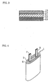
- Fig. 3 is a cross sectional view of a laminated casing utilized in a nonaqueous electrolyte secondary cell according to the present invention
- Fig. 4 is a perspective view of an electrode assembly utilized in a nonaqueous electrolyte secondary cell according to the present invention.
- a thin cell of the present invention comprises an electrode assembly 1 placed in an enclosure space 2.
- This enclosure space 2 as shown in Fig. 1, is formed by sealing the upper edge portion, lower edge portion, and central portion of a laminated casing 3 with sealing parts 4a, 4b, and 4c respectively.
- the electrode assembly 1 is prepared by winding a positive electrode 5, composed mainly of a positive electrode active material comprising LiCoO 2 , a negative electrode 6, composed mainly of a negative electrode active material comprising natural graphite, and a separator (not shown in Fig. 4) for separating the electrodes, into a flat spiral-shape.
- a gel polymer exists between the positive electrode 5 and the separator and between the negative electrode 6 and the separator.
- This gel polymer is formed by adding LiPF 6 and LiN(C 2 F 5 SO 2 ) 2 , serving as electrolyte salts, at a mole ratio of 5:95, to a mixed solvent comprising 30 mass% ethylene carbonate (EC) and 70 mass% diethyl carbonate (DEC) and mixing to form a liquid electrolyte, mixing a pregel comprising polyethylene glycol diacrylate with the liquid electrolyte, and then heating and polymerizing this mixture.
- EC ethylene carbonate
- DEC diethyl carbonate
- the oxidation potentials of the ethylene carbonate and the diethyl carbonate versus Li/Li+ were determined by using CV (cyclic voltammetry) and were approximately 4.9 V and 5.0 V respectively.
- the basic construction of the laminated casing 3 is one in which resin layers 13 (thickness: 30 ⁇ m) comprising polypropylene are bonded to both sides of aluminum layer 11 (thickness 30 ⁇ m) by means of adhesive layers 12 (thickness: 5 ⁇ m) comprising denatured polypropylene disposed therebetween.
- the positive electrode 5 is attached to a positive electrode lead 7 comprising aluminum, and the negative electrode 6 is attached to a negative electrode lead 8 comprising nickel, making the construction one in which chemical energy generated in the cell can be released as electrical energy outside the cell.
- a cell having the above-described construction is prepared as follows.
- a positive electrode active material comprising LiCoO 2
- 5 mass% of a carbon-based conductivity enhancer comprising acetylene black, graphite, and the like
- a binder comprising polyvinylidene fluoride (PVDF)
- an organic solvent comprising N-methylpyrrolidone
- a positive electrode substrate (thickness: 20 ⁇ m) comprising aluminum foil or aluminum mesh by using for example, a die coater or a doctor blade in the case of a slurry and for example, the roll coating method in the case of a paste
- this positive electrode substrate was dried in a dryer eliminating the organic solvent that was necessary in the preparation of the slurry or paste. Then, by rolling this electrode plate with a roller press, the positive electrode 5 having a thickness of 0.17 mm was prepared.
- PVDF polyvinylidene fluoride
- a negative electrode substrate (thickness: 20 ⁇ m) comprising copper foil by using for example, a die coater or a doctor blade in the case of a slurry and for example, the roll coating method in the case of a paste
- this negative electrode substrate was dried in a dryer eliminating the organic solvent that was necessary in the preparation of the slurry or paste. Then, by rolling this electrode plate with a roller press, the negative electrode 6 having a thickness of 0.14 mm was prepared.
- both electrodes 5 and 6 were put together with a separator composed of a microporous film (thickness: 0.025 mm, porosity: 50%) comprising polyolefin-based resin, which has low reactivity with organic solvents and is inexpensive, disposed therebetween.
- a separator composed of a microporous film (thickness: 0.025 mm, porosity: 50%) comprising polyolefin-based resin, which has low reactivity with organic solvents and is inexpensive, disposed therebetween.
- the center lines in the direction of the widths of both the positive and the negative electrodes were lined up.
- the flat spiral-shaped electrode assembly 1 was prepared by winding the electrodes with a winding machine and taping down the outermost coil.
- the electrode assembly 1 was enclosed in the enclosure space 2 of this tube-shaped aluminum laminated film.
- the electrode assembly 1 was arranged so that both current collector tabs 7 and 8 projected from one of the openings of the tube-shaped aluminum laminated film.
- the aluminum laminated film at the opening from which the current collector tabs 7 and 8 projected was welded and sealed to form the sealing part 4a.
- a high-frequency induction welding device was used.
- the liquid electrolyte having been prepared by adding LiPF 6 and LiN(C 2 F 5 SO 2 ) 2 , serving as electrolyte salts, at a mole ratio of 5:95, to a mixed solvent comprising 30 mass% ethylene carbonate and 70 mass% diethyl carbonate and mixing, was poured in the enclosure space 2, the edge portions of the aluminum laminated film on the opposite side from sealing part 4a were welded to form a sealing part 4b.
- the pregel inside the laminated casing was crosslinked and polymerized by heating the laminated casing to form a gel, and a nonaqueous electrolyte secondary cell was prepared.
- cell A1 of the present invention A cell prepared in this way is hereinafter referred to as cell A1 of the present invention.
- Cells prepared in this way are hereinafter referred to as cells A2 to A13 of the present invention respectively.
- the cells A1 to A13 of the present invention and the comparative cells X1 to X7 were charged according to the conditions described below and a discharge characteristic was investigated. The results are shown together with Table 2 above. It is to be noted that the discharge characteristic was calculated from the expression, discharge capacity when discharged at a current of 1000 mA/discharge capacity when discharged at a current of 100 mA ⁇ 100 (%).
- Cells are discharged at a current of 100 mA and at a current of 1000 mA, until cell voltages of 2.7 V are reached respectively.
- LiCoO 2 in addition to LiCoO 2 used above, for example, LiNiO 2 , LiMn 2 O 4 , or complex compounds of these substances, or conductive polymers such as polyaniline, polypyrrole, and the like, can be suitably used.
- conductive polymers such as polyaniline, polypyrrole, and the like
- carbon black, coke, glassy carbon, carbon fiber, the baked form of these substances, and the like can be suitably used.
- Solvents are not limited to those solvents used above, and it is possible to use solvents in which solutions with a comparatively high relative permittivity such as propylene carbonate, vinylene carbonate, and ⁇ -butyrolactone, and solvents with a low viscosity and low boiling point such as diethyl carbonate, methyl ethyl carbonate, tetrahydrofuran, 1,2-dimethoxyethane, 1,3-dioxolane, 2-methoxytetrahydrofuran, and diethyl ether, are mixed at a suitable ratio.
- solvents with an oxidation potential of 4.8 V or higher versus Li/Li + be used.
- electrolyte salts are not limited to LiPF 6 or LiN(C 2 F 5 SO 2 ) 2 used above, and it is possible to use electrolyte salts such as LiN(CF 3 SO 2 ) 2 , LiClO 4 , and LiBF 4 .
- polyalkylene glycol diacrylate a specific example being polypropylene glycol diacrylate
- polyalkylene glycol dimethacrylate specific examples being polyethylene glycol dimethacrylate and polypropylene glycol dimethacrylate
- ether-based polymers carbonate-based polymers, acrylonitrile-based polymers, and copolymers comprising two or more of these polymers, or crosslinked polymers, fluorine-based polymers, and the like
- the casing is not limited to a laminated casing, and a casing that changes shape with a slight increase in the internal pressure of the cell can of course be applied to the present invention.
Landscapes
- Chemical & Material Sciences (AREA)
- Chemical Kinetics & Catalysis (AREA)
- General Chemical & Material Sciences (AREA)
- Electrochemistry (AREA)
- Dispersion Chemistry (AREA)
- Inorganic Chemistry (AREA)
- Engineering & Computer Science (AREA)
- Manufacturing & Machinery (AREA)
- General Physics & Mathematics (AREA)
- Physics & Mathematics (AREA)
- Condensed Matter Physics & Semiconductors (AREA)
- Secondary Cells (AREA)
- Sealing Battery Cases Or Jackets (AREA)
- Cell Separators (AREA)
- Battery Electrode And Active Subsutance (AREA)
Abstract
Description

| Polymer | Mixed solvent (proportion) | Pregel (proportion) | Cell |
| I | ethylene carbonate | polyethylene glycol | A1 |
| (30 mass%) | diacrylate | A4 | |
| + | (30 mass%) | A7 | |
| diethyl carbonate | + | A10 | |
| (70 mass%) | liquid electrolyte (70 mass%) | A13 | |
| II | ethylene carbonate | polyethylene glycol | A2 |
| (30 mass%) | diacrylate | A5 | |
| + | (10 mass%) | A8 | |
| diethyl carbonate (70 mass%) | + | A11 | |
| liquid electrolyte (90 mass%) | X5 | ||
| III | ethylene carbonate | polyethylene glycol | A3 |
| (30 mass%) | diacrylate | A6 | |
| + | (10 mass%) | A9 | |
| diethyl carbonate | + | A12 | |
| (60 mass%) + ethyl acetate (10 mass%) | liquid electrolyte (90 mass%) | X6 | |
| IV | ethylene carbonate | polyethylene glycol | X1 |
| (30 mass%) | diacrylate | X2 | |
| + | (3 mass%) | X3 | |
| diethyl carbonate | + | X4 | |
| (70 mass%) | liquid electrolyte (97 mass%) | X7 |

Claims (7)
- A nonaqueous electrolyte secondary cell comprising:an electrode assembly comprising a positive electrode, a negative electrode, and a separator disposed therebetween, the positive electrode and negative electrode being capable of intercalating and deintercalating lithium ions, and the electrode assembly being enclosed in a casing which changes shape with a slight increase in the internal pressure of the cell; anda gel polymer containing a nonaqueous liquid electrolyte, the gel polymer existing between the positive electrode and the separator and bonding the positive electrode and the separator;wherein the adhesive strength between the separator and the positive electrode is 0.02 N/10mm or higher.
- A nonaqueous electrolyte secondary cell according to claim 1, wherein the electrode assembly is such that the positive electrode and the negative electrode are wound to form a flat spiral-shape.
- A nonaqueous electrolyte secondary cell according to claim 1 or 2 wherein the casing is a laminated casing.
- A nonaqueous electrolyte secondary cell according to claim 1, 2 or 3 wherein the porosity of the separator is 60% or less and the proportion of polymer component in the gel polymer is 5% by mass or more.
- A nonaqueous electrolyte secondary cell according to claim 4 wherein the porosity of the separator is 45% or higher and the proportion of polymer component in the gel polymer is less than 30% by mass.
- A nonaqueous electrolyte secondary cell according to any preceding claim wherein the oxidation potential of the gel polymer is 4.8 V or higher versus Li/Li+.
- A method of producing a nonaqueous electrolyte secondary cell comprising the steps of:preparing an electrode assembly having a flat spiral-shape by winding a positive electrode and a negative electrode with a separator disposed therebetween, the positive electrode and the negative electrode being capable of intercalating and deintercalating lithium ions;enclosing the electrode assembly in a casing which changes shape with a slight increase in the internal pressure of the cell; andputting together the positive electrode, separator, and the negative electrode such that after a pregel comprising a liquid electrolyte and a polymer precursor is poured into the casing, the pregel crosslinks and polymerizes by heating to form a gel, and the adhesive strength between the positive electrode and the separator is 0.02 N/10mm or higher.
Applications Claiming Priority (2)
| Application Number | Priority Date | Filing Date | Title |
|---|---|---|---|
| JP2000098409A JP4201459B2 (en) | 2000-03-31 | 2000-03-31 | Non-aqueous electrolyte secondary battery and manufacturing method thereof |
| JP2000098409 | 2000-03-31 |
Publications (3)
| Publication Number | Publication Date |
|---|---|
| EP1139480A2 true EP1139480A2 (en) | 2001-10-04 |
| EP1139480A3 EP1139480A3 (en) | 2003-12-17 |
| EP1139480B1 EP1139480B1 (en) | 2008-09-10 |
Family
ID=18612893
Family Applications (1)
| Application Number | Title | Priority Date | Filing Date |
|---|---|---|---|
| EP01302970A Expired - Lifetime EP1139480B1 (en) | 2000-03-31 | 2001-03-30 | Nonaqueous electrolyte secondary cell and method of producing the same |
Country Status (9)
| Country | Link |
|---|---|
| US (1) | US6689508B2 (en) |
| EP (1) | EP1139480B1 (en) |
| JP (1) | JP4201459B2 (en) |
| KR (1) | KR100742197B1 (en) |
| CN (1) | CN1197181C (en) |
| CA (1) | CA2343458A1 (en) |
| DE (1) | DE60135700D1 (en) |
| HK (1) | HK1041109B (en) |
| TW (1) | TW517405B (en) |
Families Citing this family (18)
| Publication number | Priority date | Publication date | Assignee | Title |
|---|---|---|---|---|
| KR100922740B1 (en) * | 2002-01-07 | 2009-10-22 | 삼성에스디아이 주식회사 | Separator for lithium battery containing cationic polymer, electrode and lithium battery employing same |
| JP2003217673A (en) * | 2002-01-23 | 2003-07-31 | Japan Storage Battery Co Ltd | Non-aqueous electrolyte secondary battery and method of manufacturing the same |
| JP2003229174A (en) * | 2002-01-31 | 2003-08-15 | Sanyo Electric Co Ltd | Non-aqueous electrolyte secondary battery using a film-like package |
| US7979694B2 (en) * | 2003-03-03 | 2011-07-12 | Cisco Technology, Inc. | Using TCP to authenticate IP source addresses |
| JP2004281278A (en) * | 2003-03-17 | 2004-10-07 | Sony Corp | battery |
| KR20050031998A (en) * | 2003-09-30 | 2005-04-06 | 다이니폰 인사츠 가부시키가이샤 | Electrode plate for nonaqueous electrolyte secondary battery, method of producing the same and nonaqueous electrolyte secondary battery |
| JP2008047398A (en) * | 2006-08-14 | 2008-02-28 | Sony Corp | Nonaqueous electrolyte secondary battery |
| US8156557B2 (en) * | 2007-01-04 | 2012-04-10 | Cisco Technology, Inc. | Protection against reflection distributed denial of service attacks |
| JP4930176B2 (en) * | 2007-05-07 | 2012-05-16 | トヨタ自動車株式会社 | Fuel cell, fuel cell metal separator, and fuel cell manufacturing method |
| KR100891383B1 (en) | 2007-05-21 | 2009-04-02 | 삼성에스디아이 주식회사 | Pouch Type Secondary Battery |
| US9755269B2 (en) * | 2007-11-30 | 2017-09-05 | Air Products And Chemicals, Inc. | Dodecaborate salt radical anion compositions and methods for making and using such compositions |
| TWI398027B (en) * | 2010-04-14 | 2013-06-01 | Hon Hai Prec Ind Co Ltd | Lithium battery and method for making the same |
| TWI398030B (en) * | 2010-05-24 | 2013-06-01 | Hon Hai Prec Ind Co Ltd | Lithium ion energy-stroage battery |
| TWI398031B (en) * | 2010-05-24 | 2013-06-01 | Hon Hai Prec Ind Co Ltd | Lithium ion battery assembly |
| TWI418076B (en) * | 2010-05-24 | 2013-12-01 | Hon Hai Prec Ind Co Ltd | Lithium ion power battery |
| EP3298643B1 (en) * | 2015-05-21 | 2019-06-12 | Basf Se | Glass-ceramic electrolytes for lithium-sulfur batteries |
| HUE048007T2 (en) | 2015-11-19 | 2020-05-28 | Asahi Chemical Ind | Separator for electricity storage devices, electrode body using same, and electricity storage device |
| HUE071250T2 (en) * | 2019-02-22 | 2025-08-28 | Lg Energy Solution Ltd | Separator for lithium secondary battery |
Family Cites Families (16)
| Publication number | Priority date | Publication date | Assignee | Title |
|---|---|---|---|---|
| JP3427570B2 (en) * | 1994-10-26 | 2003-07-22 | ソニー株式会社 | Non-aqueous electrolyte secondary battery |
| JP3225867B2 (en) * | 1996-12-18 | 2001-11-05 | 三菱電機株式会社 | Lithium ion secondary battery and method of manufacturing the same |
| JPH1167273A (en) * | 1997-08-21 | 1999-03-09 | Toshiba Corp | Lithium secondary battery |
| EP0959513B1 (en) * | 1997-11-19 | 2007-09-05 | Mitsubishi Denki Kabushiki Kaisha | Lithium ion secondary battery and manufacture thereof |
| WO1999033136A1 (en) * | 1997-12-22 | 1999-07-01 | Mitsubishi Denki Kabushiki Kaisha | Lithium ion secondary battery and its manufacture |
| KR19990057608A (en) * | 1997-12-30 | 1999-07-15 | 조정래 | Non-aqueous electrolyte secondary battery and manufacturing method thereof |
| JP3426253B2 (en) * | 1998-01-19 | 2003-07-14 | 三菱電機株式会社 | Battery |
| JPH11219728A (en) | 1998-01-30 | 1999-08-10 | Hitachi Maxell Ltd | Polymer battery |
| JP3850977B2 (en) * | 1998-03-31 | 2006-11-29 | 三洋電機株式会社 | Method for producing polymer solid electrolyte battery |
| JP4558110B2 (en) * | 1998-06-08 | 2010-10-06 | 帝人株式会社 | Polymer electrolyte secondary battery and manufacturing method thereof |
| JP2000067917A (en) * | 1998-08-24 | 2000-03-03 | Hitachi Maxell Ltd | Polymer lithium ion secondary battery |
| JP3447610B2 (en) | 1999-04-23 | 2003-09-16 | 日本電気株式会社 | Electrode separator laminate, method for producing the same, and battery using the same |
| JP3516133B2 (en) | 1999-05-12 | 2004-04-05 | 日本電池株式会社 | Manufacturing method of non-aqueous electrolyte secondary battery |
| JP3683144B2 (en) * | 1999-12-16 | 2005-08-17 | 日本電気株式会社 | Non-aqueous electrolyte secondary battery with film |
| JP4106644B2 (en) * | 2000-04-04 | 2008-06-25 | ソニー株式会社 | Battery and manufacturing method thereof |
| EP1276165A1 (en) * | 2001-07-12 | 2003-01-15 | Japan Storage Battery Co., Ltd. | Nonaqueous secondary cell |
-
2000
- 2000-03-31 JP JP2000098409A patent/JP4201459B2/en not_active Expired - Fee Related
-
2001
- 2001-03-20 KR KR1020010014234A patent/KR100742197B1/en not_active Expired - Fee Related
- 2001-03-30 TW TW090107739A patent/TW517405B/en not_active IP Right Cessation
- 2001-03-30 DE DE60135700T patent/DE60135700D1/en not_active Expired - Fee Related
- 2001-03-30 EP EP01302970A patent/EP1139480B1/en not_active Expired - Lifetime
- 2001-03-30 US US09/820,930 patent/US6689508B2/en not_active Expired - Fee Related
- 2001-03-30 CN CNB011122188A patent/CN1197181C/en not_active Expired - Fee Related
- 2001-03-30 CA CA002343458A patent/CA2343458A1/en not_active Abandoned
-
2002
- 2002-03-05 HK HK02101680.1A patent/HK1041109B/en not_active IP Right Cessation
Also Published As
| Publication number | Publication date |
|---|---|
| KR100742197B1 (en) | 2007-07-25 |
| HK1041109B (en) | 2005-10-21 |
| US6689508B2 (en) | 2004-02-10 |
| TW517405B (en) | 2003-01-11 |
| CN1197181C (en) | 2005-04-13 |
| JP4201459B2 (en) | 2008-12-24 |
| DE60135700D1 (en) | 2008-10-23 |
| JP2001283927A (en) | 2001-10-12 |
| KR20010100821A (en) | 2001-11-14 |
| CA2343458A1 (en) | 2001-09-30 |
| US20010038941A1 (en) | 2001-11-08 |
| HK1041109A1 (en) | 2002-06-28 |
| EP1139480B1 (en) | 2008-09-10 |
| EP1139480A3 (en) | 2003-12-17 |
| CN1319903A (en) | 2001-10-31 |
Similar Documents
| Publication | Publication Date | Title |
|---|---|---|
| KR102160701B1 (en) | Electrode with Perforated Current Collector, Lithium Secondary Battery containing the Same | |
| US8247100B2 (en) | Electrochemical device | |
| US6689508B2 (en) | Nonaqueous electrolyte secondary cell and method of producing the same | |
| KR100331209B1 (en) | Non-aqueous Electrolyte Secondary Battery | |
| US20060019151A1 (en) | Non-aqueous electrolyte battery | |
| US8343669B2 (en) | Electrochemical device | |
| JP4366723B2 (en) | Non-aqueous electrolyte secondary battery | |
| KR102686803B1 (en) | Lithium secondary battery | |
| JP4218792B2 (en) | Non-aqueous secondary battery | |
| CN120545636A (en) | Battery cells and battery packs | |
| JP4245429B2 (en) | Battery with spiral electrode group | |
| US12249720B2 (en) | Electrode assembly having enhanced safety and lithium secondary battery comprising same | |
| JPH10228930A (en) | Electrode sheet and battery | |
| US20030152836A1 (en) | Nonaqueous electrolyte secondary cell | |
| JP4248044B2 (en) | Non-aqueous electrolyte secondary battery | |
| EP4503244A1 (en) | Secondary battery | |
| KR102673253B1 (en) | Lithium secondary battery | |
| JP3444302B2 (en) | Non-aqueous electrolyte secondary battery | |
| JP2005123058A (en) | Nonaqueous electrolyte secondary battery | |
| JP4359941B2 (en) | Non-aqueous electrolyte secondary battery | |
| KR20240002948A (en) | Cylindrical lithium secondary battery | |
| KR20060009411A (en) | Large capacity high rate lithium ion battery | |
| JP4251774B2 (en) | Non-aqueous electrolyte secondary battery and manufacturing method thereof | |
| JP4501180B2 (en) | Non-aqueous polymer secondary battery | |
| JPH1173994A (en) | Lithium secondary battery |
Legal Events
| Date | Code | Title | Description |
|---|---|---|---|
| PUAI | Public reference made under article 153(3) epc to a published international application that has entered the european phase |
Free format text: ORIGINAL CODE: 0009012 |
|
| AK | Designated contracting states |
Kind code of ref document: A2 Designated state(s): AT BE CH CY DE DK ES FI FR GB GR IE IT LI LU MC NL PT SE TR |
|
| AX | Request for extension of the european patent |
Free format text: AL;LT;LV;MK;RO;SI |
|
| PUAL | Search report despatched |
Free format text: ORIGINAL CODE: 0009013 |
|
| AK | Designated contracting states |
Kind code of ref document: A3 Designated state(s): AT BE CH CY DE DK ES FI FR GB GR IE IT LI LU MC NL PT SE TR |
|
| AX | Request for extension of the european patent |
Extension state: AL LT LV MK RO SI |
|
| 17P | Request for examination filed |
Effective date: 20040604 |
|
| AKX | Designation fees paid |
Designated state(s): DE FI FR GB |
|
| 17Q | First examination report despatched |
Effective date: 20050728 |
|
| GRAP | Despatch of communication of intention to grant a patent |
Free format text: ORIGINAL CODE: EPIDOSNIGR1 |
|
| GRAS | Grant fee paid |
Free format text: ORIGINAL CODE: EPIDOSNIGR3 |
|
| GRAA | (expected) grant |
Free format text: ORIGINAL CODE: 0009210 |
|
| AK | Designated contracting states |
Kind code of ref document: B1 Designated state(s): DE FI FR GB |
|
| REG | Reference to a national code |
Ref country code: GB Ref legal event code: FG4D |
|
| REF | Corresponds to: |
Ref document number: 60135700 Country of ref document: DE Date of ref document: 20081023 Kind code of ref document: P |
|
| PG25 | Lapsed in a contracting state [announced via postgrant information from national office to epo] |
Ref country code: FI Free format text: LAPSE BECAUSE OF FAILURE TO SUBMIT A TRANSLATION OF THE DESCRIPTION OR TO PAY THE FEE WITHIN THE PRESCRIBED TIME-LIMIT Effective date: 20080910 |
|
| PGFP | Annual fee paid to national office [announced via postgrant information from national office to epo] |
Ref country code: GB Payment date: 20090303 Year of fee payment: 9 |
|
| PLBE | No opposition filed within time limit |
Free format text: ORIGINAL CODE: 0009261 |
|
| STAA | Information on the status of an ep patent application or granted ep patent |
Free format text: STATUS: NO OPPOSITION FILED WITHIN TIME LIMIT |
|
| 26N | No opposition filed |
Effective date: 20090611 |
|
| PGFP | Annual fee paid to national office [announced via postgrant information from national office to epo] |
Ref country code: DE Payment date: 20090320 Year of fee payment: 9 Ref country code: FR Payment date: 20090331 Year of fee payment: 9 |
|
| GBPC | Gb: european patent ceased through non-payment of renewal fee |
Effective date: 20100330 |
|
| REG | Reference to a national code |
Ref country code: FR Ref legal event code: ST Effective date: 20101130 |
|
| PG25 | Lapsed in a contracting state [announced via postgrant information from national office to epo] |
Ref country code: FR Free format text: LAPSE BECAUSE OF NON-PAYMENT OF DUE FEES Effective date: 20100331 |
|
| PG25 | Lapsed in a contracting state [announced via postgrant information from national office to epo] |
Ref country code: DE Free format text: LAPSE BECAUSE OF NON-PAYMENT OF DUE FEES Effective date: 20101001 |
|
| PG25 | Lapsed in a contracting state [announced via postgrant information from national office to epo] |
Ref country code: GB Free format text: LAPSE BECAUSE OF NON-PAYMENT OF DUE FEES Effective date: 20100330 |