EP1139389A1 - Arrangement for etching a semiconductor substrate and method for cleaning a filter in the arrangement - Google Patents
Arrangement for etching a semiconductor substrate and method for cleaning a filter in the arrangement Download PDFInfo
- Publication number
- EP1139389A1 EP1139389A1 EP00106632A EP00106632A EP1139389A1 EP 1139389 A1 EP1139389 A1 EP 1139389A1 EP 00106632 A EP00106632 A EP 00106632A EP 00106632 A EP00106632 A EP 00106632A EP 1139389 A1 EP1139389 A1 EP 1139389A1
- Authority
- EP
- European Patent Office
- Prior art keywords
- filter
- cleaning
- substance
- valve
- inflow
- Prior art date
- Legal status (The legal status is an assumption and is not a legal conclusion. Google has not performed a legal analysis and makes no representation as to the accuracy of the status listed.)
- Withdrawn
Links
Images




Classifications
-
- H—ELECTRICITY
- H10—SEMICONDUCTOR DEVICES; ELECTRIC SOLID-STATE DEVICES NOT OTHERWISE PROVIDED FOR
- H10P—GENERIC PROCESSES OR APPARATUS FOR THE MANUFACTURE OR TREATMENT OF DEVICES COVERED BY CLASS H10
- H10P72/00—Handling or holding of wafers, substrates or devices during manufacture or treatment thereof
- H10P72/04—Apparatus for manufacture or treatment
- H10P72/0402—Apparatus for fluid treatment
- H10P72/0418—Apparatus for fluid treatment for etching
- H10P72/0422—Apparatus for fluid treatment for etching for wet etching
- H10P72/0426—Apparatus for fluid treatment for etching for wet etching with the semiconductor substrates being dipped in baths or vessels
-
- H—ELECTRICITY
- H10—SEMICONDUCTOR DEVICES; ELECTRIC SOLID-STATE DEVICES NOT OTHERWISE PROVIDED FOR
- H10P—GENERIC PROCESSES OR APPARATUS FOR THE MANUFACTURE OR TREATMENT OF DEVICES COVERED BY CLASS H10
- H10P72/00—Handling or holding of wafers, substrates or devices during manufacture or treatment thereof
- H10P72/04—Apparatus for manufacture or treatment
- H10P72/0402—Apparatus for fluid treatment
- H10P72/0406—Apparatus for fluid treatment for cleaning followed by drying, rinsing, stripping, blasting or the like
- H10P72/0411—Apparatus for fluid treatment for cleaning followed by drying, rinsing, stripping, blasting or the like for wet cleaning or washing
Definitions
- the present invention refers to an arrangement for etching a semiconductor substrate and a method for cleaning a filter in said arrangement.
- Filters are used for purifying a solution by removing particles which exist in the solution.
- a filter can be used in a semiconductor factory to purify an etching solution consisting of an aqueous phosphoric acid solution which has been used for the etching of a silicon-nitride film formed on a semiconductor wafer. This technique is described in the patent US 5,420,421.
- a problem that arises when using a filter is that the filter has a limited lifetime due to contamination with the filtered particles. As a result, the filter has to be exchanged for a new one.
- the fittings for some filters are made of steel, but steel is not a favourable material for semiconductor manufacturing, because it can contaminate the wafer. Therefore other filters are made from synthetic materials which are somehow softer and can be damaged during installation or removal so that they cannot be recycled.
- an arrangement for etching a semiconductor substrate comprising: a process basin to receive a wafer substrate, a filter connected to the process basin, a process inflow connected to said filter, a process outflow connected to said filter, a cleaning inflow and a cleaning outflow connected to said filter and a valve with a first and a second operating position connected to said filter, in that in said first operating position an etching substance can flow from the process inflow through the filter to the process outflow and in said second operating position a cleaning substance can flow from the cleaning inflow through the filter to the cleaning outflow.
- the filter can be operated in a processing circulation for cleaning a processing substance which is flowing through the filter.
- the flow of the processing substance through the filter can be interrupted, so that the filter is separated from the process circulation, which is interrupted.
- the valves are operated in a way that a cleaning substance which cleans the filter can flow through the filter.
- the cleaning substance can flow through the filter in the same or the opposite direction as the processing substance.
- the process basin containing the processing substance for processing a wafer substrate is connected to the filter.
- the process basin is the place where the wafer substrate is processed. For example some particles which are removed from the substrate are present in the processing substance afterwards.
- the processing substance can then be cleaned with the filter by removing the particles from the processing substance.
- a further embodiment of the invention contains a pump which is connected to the process basin and the filter to establish a process circulation.
- the processing substance circulates in the process circulation for maintaining a pure processing substance.
- the processing substance flows out of the processing basin and is pumped with the pump through the filter.
- the filter cleans the processing substance, which flows back into the process basin.
- the advantage of this circulation is that the processing substance is continuously cleaned by the filter, while cycling in the circulation.
- the processing substance contains phosphoric acid.
- Phosphoric acid can be used for etching silicon-nitride which is formed on a wafer substrate.
- the cleaning substance contains hydrofluoric acid.
- the etching of silicon-nitride with phosphoric acid can be described with the following reaction equation: Si 3 N 4 + 6H 2 O reacts under the effect of H 3 PO 4 to 3SiO 2 + 4NH 3 .
- residues of SiO 2 remain in the phosphoric acid. These residues are collected in the filter and can block up the filter after a certain range of time.
- the residues consist of silicon-dioxide they can be dissolved with hydrofluoric acid and the filter is advantageously cleaned.
- a further embodiment of the invention connects a tank to the filter.
- the tank is used for flushing the processing substance out of the processing circulation into the tank.
- the processing substance contains phosphoric acid it is normally heated to a temperature above the boiling point at a certain concentration e.g. 160 °C.
- the tank can be used as a cooling down tank for the processing substance, before the processing substance is forwarded to a drain or a neutralization.
- a supply for a rinsing substance can be used to remove the hydrofluoric acid from the filter after cleaning it.
- the cleaning inflow and the cleaning outflow are connected and establish a cleaning circulation.
- This arrangement can be used to circulate the cleaning substance in the cleaning circulation and the filter is continuously penetrated by the cleaning substance.
- a second pump is connected to the cleaning inflow.
- the second pump is used to circulate the cleaning substance in the cleaning circulation and to force the cleaning substance through the filter.
- a second filter is connected to the process inflow and the process outflow so that the first filter and the second filter can alternately clean the processing substance or can be cleaned by the cleaning substance.
- the second filter is cleaned while the first filter is operating and vice versa.
- Valves and tubes are foreseen in an arrangement, that allows the cleaning and rinsing of one filter while the other filter is cleaning the processing substance.
- a method for cleaning a filter in an above mentioned arrangement for etching a semiconductor substrate wherein a valve is operated in a first position to filter a processing substance while the etching substance is flowing from a process inflow through the filter to a process outflow to etch a semiconductor substrate and the valve is operated in a second position to clean the filter with a cleaning substance flowing from a cleaning inflow through the filter to a cleaning outflow.
- This method cleans a filter without disassembling the filter from the system. This reduces the time needed for cleaning the filter. With this method it is also possible to clean filters which are mechanically weak and cannot be mounted to the processing circulation a second time. This recycling of a filter saves filter costs.
- a filter 1 is connected to a process inflow 2, a process outflow 3, a cleaning inflow 4 and a cleaning outflow 5.
- the process inflow 2 can be opened and closed with the first valve 6, the process outflow 3 can be opened and closed with the second valve 7, the cleaning inflow 4 can be opened and closed with the third valve 8 and the cleaning outflow 5 can be opened and closed with the fourth valve 9.
- the process inflow 2 is at the opposite side to the cleaning inflow 4. That means that the cleaning flow direction for cleaning the filter 1 is opposite to the process flow direction.
- Figure 2 shows a second example of the invention where the filter 1 is connected to a process inflow 2, a process outflow 3, a cleaning inflow 4 and a cleaning outflow 5. Additionally there is a fifth valve 10 which can alternate the flow to the filter 1 between the process inflow 2 and the cleaning outflow 5.
- a sixth valve 11 is connected to the filter 1 and can alternate the substance flow through the filter between the process outflow 3 and the cleaning inflow 4.
- the process flow direction is opposite to the cleaning flow direction through the filter. It is also possible to build the cleaning flow direction in the same direction through the filter as the processing flow direction.
- Figure 3 shows a third example of the invention, comprising a filter 1 which is connected to a process inflow 2, a process outflow 3, a cleaning inflow 4 and a cleaning outflow 5.
- a filter 1 which is connected to a process inflow 2, a process outflow 3, a cleaning inflow 4 and a cleaning outflow 5.
- no valves are shown because the valves can be arranged in other parts of the system.
- FIG 4 is an example of the invented filter with a processing circulation and a cleaning circulation.
- the filter 1 is connected to a process inflow 2 which can be opened and closed by the first valve 6, connected to a process outflow 3 which can be opened and closed with a second valve 7, connected to a cleaning inflow 4 which can be opened and closed with a third valve 8 and connected to a cleaning outflow 5 which can be opened and closed with a fourth valve 9.
- a pump 12 which is also connected to the process basin 14.
- the process basin 14 contains a processing substance 24 and a wafer substrate 15 which is processed with the processing substance 24.
- the processing substance 24 is comprising phosphoric acid and is pumped with the help of the pump 12 through the filter 1.
- the filter flows out of the filter through the process outflow 3 and through a heater 13, which helps to heat the processing substance 24 to an adequate temperature.
- the heater 13 itself is connected to the process basin 14, so that the filtered processing substance 24 can flow back into the process basin 14.
- the seventh valve 17, which is connected to the filter is opened and the processing substance 24 flows through the seventh valve 17 into a tank 18.
- the tank 18 can be used to cool down the processing substance 24 before draining, neutralising or recycling it.
- the filter 1 can be blocked so that it is necessary to clean it.
- the first valve 6 and the second valve 7 are closed and the fourth valve 9 and the third valve 8 are opened to open the cleaning inflow 4 and the cleaning outflow 5.
- a drain 23 where the cleaning substance can be drained.
- a second pump 16 which can pump a cleaning substance 25 and a rinsing substance 41 through the filter 1.
- the second pump 16 is connected to an eighth valve 21 which opens a supply 20 for a rinsing substance and is connected to a ninth valve 22 which is connected to a supply for a cleaning substance 19.
- the cleaning substance 25 is pumped through the filter 1 to remove the blocking particles in the filter through the cleaning outflow into the drain 23.
- the filter 1 is rinsed with a rinsing substance 41 to remove the cleaning substance 25 from the filter 1.
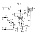
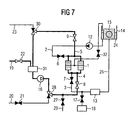
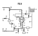
- FIGS 5 to 7 the same arrangement is shown. The difference between the figures 5 to 7 is in the state in which the arrangement is working at each particular figure.
- the blocked valves are drawn in black, the open valves are drawn with a white body.
- the active pump is also drawn with a white triangle in it, the blocking pump is drawn with a black one.
- the tubes which are transporting fluid are drawn with big grey lines, the other tubes which are not transporting a substance in this state are drawn with small black lines.
- FIG 5 there is a filter 1 which is connected to a process inflow 2 and a process outflow 3.
- the process inflow 2 can be opened and closed with the first valve 6, the process outflow 3 can be opened and closed with the second valve 7.
- the process inflow 2 is connected to a pump 12 where the triangle gives the pump direction.
- the pump 12 is connected to the process basin 14, which contains a processing substance 24 and a wafer substrate 15.
- the process outflow 3 is connected to a heater 13 where the processing substance 24 is heated while flowing through and forwarded to the process basin 14.
- the process basin 14, the pump 12, the filter 1 and the heater 13 build a process circulation 26.
- the thirteens valve 32 is open to allow degassing of the filter 1.
- the filter 1 is also connected to a cleaning outflow 5, which can be opened and closed with a fourth valve 9.
- the fourth valve 9 is connected to a twelfth valve 30, where the substance flow can be directed to the drain 23 or a reclaim tank 31.
- the reclaim tank 31 is connected to a supply of a cleaning substance 19 which can be opened and closed with a ninth valve 22.
- the outflow of the reclaim tank 31 is connected to a second pump 16 which pumps the cleaning substance 25 to an eleventh valve 28 which is connected to a supply of a rinsing substance 20 which can be opened and closed with an eighth valve 21.
- the eleventh valve 28 forwards the substance further to a tenth valve 27 which is connected to a second drain 29 and also forwards the substance to the cleaning inflow 4 which can be opened and closed with the third valve 8.
- the process circulation 26 is active so that the processing substance 24 is flowing through the pump 12 forwarded to the process inflow 2 passing the first valve 6 and the filter 1 and leaving the filter 1 through the second valve 7, being forwarded through the process outflow 3 to the heater 13 and flowing back into the process basin 14.
- the other valves in figure 5 are closed so that the other tubes are not forwarding a substance.
- the next process step can be seen in figure 6 where the processing substance 24 is forwarded into the tank 18 through the open valve 17.
- the reclaim tank 31 is emptied through the second pump 16, the eleventh valve 28, the tenth valve 27 into the second drain 29.
- the processing substance 24 can be moved into the tank 18 by gravity. Also the emptying of the reclaim tank 31 into the second drain 29 can be done by gravity.
- the first valve 6 and the second valve 7 are closed. That means, that the filter 1 is decoupled from the process circulation 26. Also the seventh valve 17 is closed so that the processing substance 24 remains in the tank 18. In addition, the thirteens valve 32 in closed so that the cleaning substance 25 can not enter the basis 14.
- the reclaim tank 31 is filled with the cleaning substance 25 from the supply for the cleaning substance 19 through the now open ninth valve 22. The cleaning substance is then proceeded through the working second pump 16 through the open eleventh valve 28 which has opened the direction from the reclaim tank 31 and not the direction from the supply for the rinsing substance 20. The cleaning substance 25 is further forwarded through the third valve 8 to the cleaning inflow 4.
- the cleaning substance is flowing through the filter 1 and cleans the filter 1. Also the tenth valve 27 is closed so that the second drain 29 is no longer active.
- the ninth valve 22 can be closed when the reclaim tank 31 is filled with enough cleaning substance.
- the fourth valve 9 and the twelfth valve 30 are open, so that the cleaning substance 25 can circulate through the filter 1, the reclaim tank 31 and the second pump 16.
- the filter 1 is now being rinsed.
- the second pump 16 is shut down, the eleventh valve 28 is opened for the flow from the supply for the rinsing substance 20 through the eighth valve 22, and the twelfth valve 30 to the drain 23.
- the rinsing substance 41 is coming from the supply for the rinsing substance 20 and has enough pressure to go through the filter 1 and into the drain 23.
- the eighth valve 21 is closed, so that no more rinsing substance 41 is flowing through the supply for the rinsing substance 20 into the cleaning circuit.
- the tenth valve 27 is opened, so that the rinsing substance 41 can flow into the second drain 29.
- the rinsing substance 41 flows into the second drain 29 and the drain 23 due to gravity, and the tubes and filters are emptied, leaving no rinsing substance behind.
- FIG. 10 is an example with two filters, a processing circulation and a cleaning circulation, where the two filters are cleaned and operated alternately.
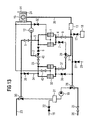
- the arrangements in the figures 10 to 14 show the same arrangement in different operating states.
- the filter 1 is connected to a process inflow 2, a process outflow 3, a cleaning inflow 4 and a cleaning outflow 5.
- the process inflow 2 can be opened and closed with the first valve 6, the process outflow 3 can be opened and closed with the second valve 7, the cleaning inflow 4 can be opened and closed with the third valve 8 and the cleaning outflow 5 can be opened and closed with the fourth valve 9.
- the process inflow 2 is connected to a pump 12, which is itself connected to a process basin 14.
- the process basin 14 is filled with the processing substance 24, which is processing the wafer substrate 15.
- the process outflow 3 is connected to a heater 13, which is itself connected to the process basin 14.
- the thirteens valve 32 is open to allow dagssifying of the filter 1.
- a second filter 33 which is also connected to the process inflow 2, which can be opened and closed with the fourteenth valve 35 and connected to the process outflow 3, which can be opened and closed with the sixteenth valve 37.
- the twentieth valve 43 is closed to prevent cleaning substance or rinsing substance from geing pumped into the basin 14.
- a nineteenth valve 40 which can lead the processing substance 24 through the first or alternately through the second filter.
- the process outflow 3 can alternately be connected to the first filter 1 and the second filter 33 through the eighteenth valve 39.
- a reclaim tank 31 is connected to a supply for a cleaning substance 19 which can be opened and closed with the ninth valve 22.
- the outflow of the reclaim tank 31 is connected to a second pump 16, which is itself connected to the first filter 1 through the third valve 8 and to the second filter 33 through the seventeenth valve 38.
- the cleaning outflow 5, which is connected to the first filter can be opened and closed with the fourth valve 9 and is connected to the second cleaning outflow 34 through the fifteenth valve 36.
- the fourth valve 9 and the fifteenth valve 36 are connected to twelfth valve 30, which is itself connected to a drain 23 and the reclaim tank 31.
- the process circulation 26 is active and processing substance 24 is flowing out of the process basin 14 through the pump 12 into the first filter 1 and out of the first filter 1 through the process outflow 3 to the heater 13, where the processing substance 24 is heated and afterwards reissued into the process basin 14.
- the processing substance 24 is flushed through the seventh valve 17 into the tank 18. Also, the reclaim tank 31 is emptied through the second pump 16, the eleventh valve 28, the tenth valve 27 into the second drain 29.
- a new processing substance 24 is filled into the process basin 14 as the processing substance 24 is in this case flowing from the process basin 14 through the pump 12 through the second filter 33 to the heater 13, where the processing substance is heated and flowing back into the process basin 14.
- the twentieth valve 42 is open to allow degassing of the filter 33.
- the reclaim tank 31 has been filled with cleaning substance 25, which is flowing driven by the second pump 16 through the eleventh valve 28 and the third valve 8 into the filter 1, cleaning the filter 1, flowing through the cleaning outflow 5 and the fourth valve 9 and the twelfth valve 30 back into the reclaim tank 31.
- the thirteenth valve 32 is now closed to prevent cleaning substance 25 from being pumped into the process basin 14. Due to this process, the filter 1 is cleaned.
- the rinsing substance 41 is flowing from the supply for the rinsing substance 20 through the open third valve 8 through the eleventh valve 28, through the filter 1, through the cleaning outflow 5, through the open valve 9, through the open valve 30 into the drain 23.
- This process is rinsing the first filter 1, while the second filter 33 is still in process and is cleaning the processing substance 24.
Landscapes
- Cleaning Or Drying Semiconductors (AREA)
Abstract
Description
- The present invention refers to an arrangement for etching a semiconductor substrate and a method for cleaning a filter in said arrangement.
- Filters are used for purifying a solution by removing particles which exist in the solution. For example, a filter can be used in a semiconductor factory to purify an etching solution consisting of an aqueous phosphoric acid solution which has been used for the etching of a silicon-nitride film formed on a semiconductor wafer. This technique is described in the patent US 5,420,421.
- A problem that arises when using a filter is that the filter has a limited lifetime due to contamination with the filtered particles. As a result, the filter has to be exchanged for a new one. The fittings for some filters are made of steel, but steel is not a favourable material for semiconductor manufacturing, because it can contaminate the wafer. Therefore other filters are made from synthetic materials which are somehow softer and can be damaged during installation or removal so that they cannot be recycled.
- It is an objective of the present invention to provide an arrangement for etching a semiconductor substrate and a method which enable the prolongation of the working lifetime of a filter.
- To attain the above mentioned objective, an arrangement for etching a semiconductor substrate is provided comprising: a process basin to receive a wafer substrate, a filter connected to the process basin, a process inflow connected to said filter, a process outflow connected to said filter, a cleaning inflow and a cleaning outflow connected to said filter and a valve with a first and a second operating position connected to said filter, in that in said first operating position an etching substance can flow from the process inflow through the filter to the process outflow and in said second operating position a cleaning substance can flow from the cleaning inflow through the filter to the cleaning outflow.
- In this configuration the filter can be operated in a processing circulation for cleaning a processing substance which is flowing through the filter. By operating the valves the flow of the processing substance through the filter can be interrupted, so that the filter is separated from the process circulation, which is interrupted. Further the valves are operated in a way that a cleaning substance which cleans the filter can flow through the filter. For example, the cleaning substance can flow through the filter in the same or the opposite direction as the processing substance. An advantage of this arrangement is that the filter can be cleaned without being removed from the arrangement.
- In an embodiment of the invention the process basin containing the processing substance for processing a wafer substrate is connected to the filter. The process basin is the place where the wafer substrate is processed. For example some particles which are removed from the substrate are present in the processing substance afterwards. The processing substance can then be cleaned with the filter by removing the particles from the processing substance.
- A further embodiment of the invention contains a pump which is connected to the process basin and the filter to establish a process circulation. The processing substance circulates in the process circulation for maintaining a pure processing substance. For example, the processing substance flows out of the processing basin and is pumped with the pump through the filter. The filter cleans the processing substance, which flows back into the process basin. The advantage of this circulation is that the processing substance is continuously cleaned by the filter, while cycling in the circulation.
- In another embodiment of the invention the processing substance contains phosphoric acid. Phosphoric acid can be used for etching silicon-nitride which is formed on a wafer substrate.
- According to another embodiment of the invention the cleaning substance contains hydrofluoric acid. The etching of silicon-nitride with phosphoric acid can be described with the following reaction equation: Si3N4 + 6H2O reacts under the effect of H3PO4 to 3SiO2 + 4NH3. As a result residues of SiO2 remain in the phosphoric acid. These residues are collected in the filter and can block up the filter after a certain range of time. As the residues consist of silicon-dioxide they can be dissolved with hydrofluoric acid and the filter is advantageously cleaned.
- A further embodiment of the invention connects a tank to the filter. The tank is used for flushing the processing substance out of the processing circulation into the tank. When the processing substance contains phosphoric acid it is normally heated to a temperature above the boiling point at a certain concentration e.g. 160 °C. The tank can be used as a cooling down tank for the processing substance, before the processing substance is forwarded to a drain or a neutralization.
- Furthermore, it is preferable to attach a supply for a rinsing substance to the cleaning inflow. The rinsing substance can be used to remove the hydrofluoric acid from the filter after cleaning it.
- Advantageously the cleaning inflow and the cleaning outflow are connected and establish a cleaning circulation. This arrangement can be used to circulate the cleaning substance in the cleaning circulation and the filter is continuously penetrated by the cleaning substance.
- According to another embodiment of the invention a second pump is connected to the cleaning inflow. The second pump is used to circulate the cleaning substance in the cleaning circulation and to force the cleaning substance through the filter.
- In a further embodiment of the invention a second filter is connected to the process inflow and the process outflow so that the first filter and the second filter can alternately clean the processing substance or can be cleaned by the cleaning substance. The second filter is cleaned while the first filter is operating and vice versa. With this arrangement the substrate processing is not interrupted by the filter cleaning process. Valves and tubes are foreseen in an arrangement, that allows the cleaning and rinsing of one filter while the other filter is cleaning the processing substance.
- To obtain the above mentioned objective concerning the method, a method for cleaning a filter in an above mentioned arrangement for etching a semiconductor substrate is provided wherein a valve is operated in a first position to filter a processing substance while the etching substance is flowing from a process inflow through the filter to a process outflow to etch a semiconductor substrate and the valve is operated in a second position to clean the filter with a cleaning substance flowing from a cleaning inflow through the filter to a cleaning outflow.
- This method cleans a filter without disassembling the filter from the system. This reduces the time needed for cleaning the filter. With this method it is also possible to clean filters which are mechanically weak and cannot be mounted to the processing circulation a second time. This recycling of a filter saves filter costs.
- Further embodiments of the invention are given in the dependent claims.
- The invention is further explained using examples with reference to figures.
- The figures show:
- Figure 1
- a filter to be used in an arrangement according to the invention;
- Figure 2
- another arrangement of the filter;
- Figure 3
- another arrangement of the filter;
- Figure 4
- an arrangement of the filter with a processing circulation and a cleaning means;
- Figures 5 to 9
- an arrangement of a filter, a processing circulation and a cleaning circulation where the different steps for operating the arrangement are shown in the successive figures;
- Figures 10 to 13
- an arrangement of a filter, a processing circulation and a cleaning circulation, where the two filters are cleaned and operated alternatively.
- In figure 1 a filter 1 is connected to a
process inflow 2, aprocess outflow 3, acleaning inflow 4 and acleaning outflow 5. Theprocess inflow 2 can be opened and closed with thefirst valve 6, theprocess outflow 3 can be opened and closed with thesecond valve 7, thecleaning inflow 4 can be opened and closed with thethird valve 8 and thecleaning outflow 5 can be opened and closed with thefourth valve 9. In the arrangement of figure 1 theprocess inflow 2 is at the opposite side to thecleaning inflow 4. That means that the cleaning flow direction for cleaning the filter 1 is opposite to the process flow direction. - Figure 2 shows a second example of the invention where the filter 1 is connected to a
process inflow 2, aprocess outflow 3, acleaning inflow 4 and acleaning outflow 5. Additionally there is afifth valve 10 which can alternate the flow to the filter 1 between theprocess inflow 2 and thecleaning outflow 5. Asixth valve 11 is connected to the filter 1 and can alternate the substance flow through the filter between theprocess outflow 3 and thecleaning inflow 4. In this example the process flow direction is opposite to the cleaning flow direction through the filter. It is also possible to build the cleaning flow direction in the same direction through the filter as the processing flow direction. - Figure 3 shows a third example of the invention, comprising a filter 1 which is connected to a
process inflow 2, aprocess outflow 3, acleaning inflow 4 and acleaning outflow 5. In figure 3 no valves are shown because the valves can be arranged in other parts of the system. - Figure 4 is an example of the invented filter with a processing circulation and a cleaning circulation. The filter 1 is connected to a
process inflow 2 which can be opened and closed by thefirst valve 6, connected to aprocess outflow 3 which can be opened and closed with asecond valve 7, connected to acleaning inflow 4 which can be opened and closed with athird valve 8 and connected to acleaning outflow 5 which can be opened and closed with afourth valve 9. Connected to theprocess inflow 2 is apump 12 which is also connected to theprocess basin 14. Theprocess basin 14 contains aprocessing substance 24 and awafer substrate 15 which is processed with theprocessing substance 24. In this example theprocessing substance 24 is comprising phosphoric acid and is pumped with the help of thepump 12 through the filter 1. Afterwards it flows out of the filter through theprocess outflow 3 and through aheater 13, which helps to heat theprocessing substance 24 to an adequate temperature. Theheater 13 itself is connected to theprocess basin 14, so that the filteredprocessing substance 24 can flow back into theprocess basin 14. After a certain amount of time theprocessing substance 24 is consumed and it has to be replaced with a new processing substance. In this case theseventh valve 17, which is connected to the filter, is opened and theprocessing substance 24 flows through theseventh valve 17 into atank 18. Thetank 18 can be used to cool down theprocessing substance 24 before draining, neutralising or recycling it. - After a certain amount of time the filter 1 can be blocked so that it is necessary to clean it. For this purpose the
first valve 6 and thesecond valve 7 are closed and thefourth valve 9 and thethird valve 8 are opened to open thecleaning inflow 4 and thecleaning outflow 5. Connected to thecleaning outflow 5 is adrain 23 where the cleaning substance can be drained. Connected to thecleaning inflow 4 is asecond pump 16, which can pump a cleaning substance 25 and a rinsing substance 41 through the filter 1. In figure 4 thesecond pump 16 is connected to aneighth valve 21 which opens asupply 20 for a rinsing substance and is connected to aninth valve 22 which is connected to a supply for a cleaningsubstance 19. To clean the filter 1 the cleaning substance 25 is pumped through the filter 1 to remove the blocking particles in the filter through the cleaning outflow into thedrain 23. Afterwards the filter 1 is rinsed with a rinsing substance 41 to remove the cleaning substance 25 from the filter 1. - In figures 5 to 7 the same arrangement is shown. The difference between the figures 5 to 7 is in the state in which the arrangement is working at each particular figure. In the figures the blocked valves are drawn in black, the open valves are drawn with a white body. The active pump is also drawn with a white triangle in it, the blocking pump is drawn with a black one. The tubes which are transporting fluid are drawn with big grey lines, the other tubes which are not transporting a substance in this state are drawn with small black lines.
- In figure 5 there is a filter 1 which is connected to a
process inflow 2 and aprocess outflow 3. Theprocess inflow 2 can be opened and closed with thefirst valve 6, theprocess outflow 3 can be opened and closed with thesecond valve 7. Theprocess inflow 2 is connected to apump 12 where the triangle gives the pump direction. Thepump 12 is connected to theprocess basin 14, which contains aprocessing substance 24 and awafer substrate 15. Theprocess outflow 3 is connected to aheater 13 where theprocessing substance 24 is heated while flowing through and forwarded to theprocess basin 14. Theprocess basin 14, thepump 12, the filter 1 and theheater 13 build aprocess circulation 26. Thethirteens valve 32 is open to allow degassing of the filter 1. The filter 1 is also connected to acleaning outflow 5, which can be opened and closed with afourth valve 9. Thefourth valve 9 is connected to atwelfth valve 30, where the substance flow can be directed to thedrain 23 or a reclaimtank 31. The reclaimtank 31 is connected to a supply of a cleaningsubstance 19 which can be opened and closed with aninth valve 22. The outflow of the reclaimtank 31 is connected to asecond pump 16 which pumps the cleaning substance 25 to aneleventh valve 28 which is connected to a supply of a rinsingsubstance 20 which can be opened and closed with aneighth valve 21. Theeleventh valve 28 forwards the substance further to atenth valve 27 which is connected to asecond drain 29 and also forwards the substance to thecleaning inflow 4 which can be opened and closed with thethird valve 8. In figure 5 theprocess circulation 26 is active so that theprocessing substance 24 is flowing through thepump 12 forwarded to theprocess inflow 2 passing thefirst valve 6 and the filter 1 and leaving the filter 1 through thesecond valve 7, being forwarded through theprocess outflow 3 to theheater 13 and flowing back into theprocess basin 14. The other valves in figure 5 are closed so that the other tubes are not forwarding a substance. - The next process step can be seen in figure 6 where the
processing substance 24 is forwarded into thetank 18 through theopen valve 17. The reclaimtank 31 is emptied through thesecond pump 16, theeleventh valve 28, thetenth valve 27 into thesecond drain 29. Theprocessing substance 24 can be moved into thetank 18 by gravity. Also the emptying of the reclaimtank 31 into thesecond drain 29 can be done by gravity. - In the next process step, which is shown in figure 7, the
first valve 6 and thesecond valve 7 are closed. That means, that the filter 1 is decoupled from theprocess circulation 26. Also theseventh valve 17 is closed so that theprocessing substance 24 remains in thetank 18. In addition, thethirteens valve 32 in closed so that the cleaning substance 25 can not enter thebasis 14. The reclaimtank 31 is filled with the cleaning substance 25 from the supply for the cleaningsubstance 19 through the now openninth valve 22. The cleaning substance is then proceeded through the working second pump 16 through the openeleventh valve 28 which has opened the direction from the reclaimtank 31 and not the direction from the supply for the rinsingsubstance 20. The cleaning substance 25 is further forwarded through thethird valve 8 to thecleaning inflow 4. The cleaning substance is flowing through the filter 1 and cleans the filter 1. Also thetenth valve 27 is closed so that thesecond drain 29 is no longer active. Theninth valve 22 can be closed when the reclaimtank 31 is filled with enough cleaning substance. Thefourth valve 9 and thetwelfth valve 30 are open, so that the cleaning substance 25 can circulate through the filter 1, the reclaimtank 31 and thesecond pump 16. - With respect to figure 8, the filter 1 is now being rinsed. For this purpose, the
second pump 16 is shut down, theeleventh valve 28 is opened for the flow from the supply for the rinsingsubstance 20 through theeighth valve 22, and thetwelfth valve 30 to thedrain 23. The rinsing substance 41 is coming from the supply for the rinsingsubstance 20 and has enough pressure to go through the filter 1 and into thedrain 23. - In figure 9, the
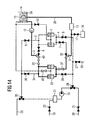
eighth valve 21 is closed, so that no more rinsing substance 41 is flowing through the supply for the rinsingsubstance 20 into the cleaning circuit. Thetenth valve 27 is opened, so that the rinsing substance 41 can flow into thesecond drain 29. The rinsing substance 41 flows into thesecond drain 29 and thedrain 23 due to gravity, and the tubes and filters are emptied, leaving no rinsing substance behind. - In the figures 10 to 14 is an example with two filters, a processing circulation and a cleaning circulation, where the two filters are cleaned and operated alternately. The arrangements in the figures 10 to 14 show the same arrangement in different operating states. In figure 10 the filter 1 is connected to a
process inflow 2, aprocess outflow 3, acleaning inflow 4 and acleaning outflow 5. Theprocess inflow 2 can be opened and closed with thefirst valve 6, theprocess outflow 3 can be opened and closed with thesecond valve 7, thecleaning inflow 4 can be opened and closed with thethird valve 8 and thecleaning outflow 5 can be opened and closed with thefourth valve 9. Theprocess inflow 2 is connected to apump 12, which is itself connected to aprocess basin 14. Theprocess basin 14 is filled with theprocessing substance 24, which is processing thewafer substrate 15. Theprocess outflow 3 is connected to aheater 13, which is itself connected to theprocess basin 14. Thethirteens valve 32 is open to allow dagssifying of the filter 1. In parallel to the filter 1, there is asecond filter 33, which is also connected to theprocess inflow 2, which can be opened and closed with thefourteenth valve 35 and connected to theprocess outflow 3, which can be opened and closed with thesixteenth valve 37. Thetwentieth valve 43 is closed to prevent cleaning substance or rinsing substance from geing pumped into thebasin 14. To distinguish between the first filter 1 and thesecond filter 33 there is anineteenth valve 40 which can lead theprocessing substance 24 through the first or alternately through the second filter. Theprocess outflow 3 can alternately be connected to the first filter 1 and thesecond filter 33 through theeighteenth valve 39. - A reclaim
tank 31 is connected to a supply for a cleaningsubstance 19 which can be opened and closed with theninth valve 22. The outflow of the reclaimtank 31 is connected to asecond pump 16, which is itself connected to the first filter 1 through thethird valve 8 and to thesecond filter 33 through theseventeenth valve 38. The cleaningoutflow 5, which is connected to the first filter, can be opened and closed with thefourth valve 9 and is connected to thesecond cleaning outflow 34 through thefifteenth valve 36. Thefourth valve 9 and thefifteenth valve 36 are connected totwelfth valve 30, which is itself connected to adrain 23 and the reclaimtank 31. - In figure 10 the
process circulation 26 is active andprocessing substance 24 is flowing out of theprocess basin 14 through thepump 12 into the first filter 1 and out of the first filter 1 through theprocess outflow 3 to theheater 13, where theprocessing substance 24 is heated and afterwards reissued into theprocess basin 14. - According to figure 11, the
processing substance 24 is flushed through theseventh valve 17 into thetank 18. Also, the reclaimtank 31 is emptied through thesecond pump 16, theeleventh valve 28, thetenth valve 27 into thesecond drain 29. - According to figure 12, a
new processing substance 24 is filled into theprocess basin 14 as theprocessing substance 24 is in this case flowing from theprocess basin 14 through thepump 12 through thesecond filter 33 to theheater 13, where the processing substance is heated and flowing back into theprocess basin 14. The twentieth valve 42 is open to allow degassing of thefilter 33. Also, the reclaimtank 31 has been filled with cleaning substance 25, which is flowing driven by thesecond pump 16 through theeleventh valve 28 and thethird valve 8 into the filter 1, cleaning the filter 1, flowing through the cleaningoutflow 5 and thefourth valve 9 and thetwelfth valve 30 back into the reclaimtank 31. Thethirteenth valve 32 is now closed to prevent cleaning substance 25 from being pumped into theprocess basin 14. Due to this process, the filter 1 is cleaned. - With respect to figure 13, the rinsing substance 41 is flowing from the supply for the rinsing
substance 20 through the openthird valve 8 through theeleventh valve 28, through the filter 1, through the cleaningoutflow 5, through theopen valve 9, through theopen valve 30 into thedrain 23. This process is rinsing the first filter 1, while thesecond filter 33 is still in process and is cleaning theprocessing substance 24. - In figure 14, the rinsing process has been stopped and the well prepared filter 1 is ready for being used when the
second filter 33 is blocked up by particles filtered out of theprocessing substance 24.
Claims (14)
- Arrangement for etching a semiconductor substrate comprising:characterised in thata process basin (14) to receive a wafer substrate (15);a filter (1) connected to the process basin (14);a process inflow (2) connected to said filter (1);a process outflow (3) connected to said filter (1);
a cleaning inflow (4) and a cleaning outflow (5) are connected to said filter (1) and a valve with a first and a second operating position is connected to said filter (1), in that in said first operating position an etching substance (24) can flow from the process inflow (2) through the filter (1) to the process outflow (3) and in said second operating position a cleaning substance (25) can flow from the cleaning inflow (4) through the filter (1) to the cleaning outflow (5). - Arrangement according to claim 1,
characterised in that
the process basin (14) contains the etching substance (24) for processing the wafer substrate (15). - Arrangement according to claim 1 or 2,
characterised in that
a pump (12) is connected to the process basin (14) and the filter (1) to establish a process circulation (26). - Arrangement according to claim 1 to 3,
characterised in that
the etching substance (24) contains phosphoric acid. - Arrangement according to claim 1 to 4,
characterised in that
the cleaning substance (25) contains hydrofluoric acid. - Arrangement according to claim 1 to 5,
characterised in that
a tank (18) is connected to the filter (1). - Arrangement according to claim 1 to 6,
characterised in that
a supply for a rinsing substance (20) is connected to the cleaning inflow (4). - Arrangement according to claim 1 to 7,
characterised in that
the cleaning inflow (4) and the cleaning outflow (5) are connected and establish a cleaning circulation (42). - Arrangement according to claim 1 to 8,
characterised in that
a second pump (16) is connected to the cleaning inflow (4). - Arrangement according to claim 1 to 9,
characterised in that
a second filter (23) is connected to the process inflow (2) and the process outflow (3), so that the filter (1) and the second filter (33) can alternately clean the etching substance (24) or be cleaned by the cleaning substance (25). - Method for cleaning a filter in an arrangement according to one of the claims 1 to 10,
characterised in that
a valve is operated in a first position to filter an etching substance (24) while the etching substance (24) is flowing from a process inflow (2) through the filter (1) to a process outflow (3) to etch a semiconductor substrate (15) and the valve is operated in a second position to clean the filter (1) with a cleaning substance (25) flowing from a cleaning inflow (4) through the filter (1) to a cleaning outflow (5). - Method according to claim 11,
characterised in that
a tank (18) is connected to the filter (1) and the etching substance (24) is filled into the tank (18) before the cleaning substance (25) flows through the filter (1). - Method according to claim 11 or 12,
characterised in that
a rinsing substance (41) is applied to the cleaning inflow (4) and the rinsing substance (41) is rinsing the filter (1). - Method according to claim 11 to 13,
characterised in that
a cleaning circulation (42) is established by operating a second pump (16) which is connected to the cleaning inflow (4) and the cleaning outflow (5), wherein the cleaning substance (25) is circulating driven by the second pump (16).
Priority Applications (1)
| Application Number | Priority Date | Filing Date | Title |
|---|---|---|---|
| EP00106632A EP1139389A1 (en) | 2000-03-28 | 2000-03-28 | Arrangement for etching a semiconductor substrate and method for cleaning a filter in the arrangement |
Applications Claiming Priority (1)
| Application Number | Priority Date | Filing Date | Title |
|---|---|---|---|
| EP00106632A EP1139389A1 (en) | 2000-03-28 | 2000-03-28 | Arrangement for etching a semiconductor substrate and method for cleaning a filter in the arrangement |
Publications (1)
| Publication Number | Publication Date |
|---|---|
| EP1139389A1 true EP1139389A1 (en) | 2001-10-04 |
Family
ID=8168258
Family Applications (1)
| Application Number | Title | Priority Date | Filing Date |
|---|---|---|---|
| EP00106632A Withdrawn EP1139389A1 (en) | 2000-03-28 | 2000-03-28 | Arrangement for etching a semiconductor substrate and method for cleaning a filter in the arrangement |
Country Status (1)
| Country | Link |
|---|---|
| EP (1) | EP1139389A1 (en) |
Cited By (1)
| Publication number | Priority date | Publication date | Assignee | Title |
|---|---|---|---|---|
| KR20160112951A (en) * | 2015-03-19 | 2016-09-28 | 도쿄엘렉트론가부시키가이샤 | Substrate liquid processing apparatus, substrate liquid processing method, and computer-readable storage medium having substrate liquid processing program stored thereon |
Citations (4)
| Publication number | Priority date | Publication date | Assignee | Title |
|---|---|---|---|---|
| JPH0731810A (en) * | 1993-07-23 | 1995-02-03 | Sony Corp | Filter cleaning method in cleaning process |
| US5651379A (en) * | 1994-08-03 | 1997-07-29 | Yieldup International | Method and apparatus for delivering ultra-low particle counts in semiconductor manufacturing |
| JPH10284458A (en) * | 1997-04-04 | 1998-10-23 | Nec Corp | Semiconductor manufacturing equipment |
| US6039835A (en) * | 1997-09-15 | 2000-03-21 | Motorola, Inc. | Etching apparatus and method of etching a substrate |
-
2000
- 2000-03-28 EP EP00106632A patent/EP1139389A1/en not_active Withdrawn
Patent Citations (5)
| Publication number | Priority date | Publication date | Assignee | Title |
|---|---|---|---|---|
| JPH0731810A (en) * | 1993-07-23 | 1995-02-03 | Sony Corp | Filter cleaning method in cleaning process |
| US5651379A (en) * | 1994-08-03 | 1997-07-29 | Yieldup International | Method and apparatus for delivering ultra-low particle counts in semiconductor manufacturing |
| JPH10284458A (en) * | 1997-04-04 | 1998-10-23 | Nec Corp | Semiconductor manufacturing equipment |
| US6055995A (en) * | 1997-04-04 | 2000-05-02 | Nec Corporation | Semiconductor manufacture apparatus |
| US6039835A (en) * | 1997-09-15 | 2000-03-21 | Motorola, Inc. | Etching apparatus and method of etching a substrate |
Non-Patent Citations (2)
| Title |
|---|
| PATENT ABSTRACTS OF JAPAN vol. 1995, no. 05 30 June 1995 (1995-06-30) * |
| PATENT ABSTRACTS OF JAPAN vol. 1999, no. 01 29 January 1999 (1999-01-29) * |
Cited By (5)
| Publication number | Priority date | Publication date | Assignee | Title |
|---|---|---|---|---|
| KR20160112951A (en) * | 2015-03-19 | 2016-09-28 | 도쿄엘렉트론가부시키가이샤 | Substrate liquid processing apparatus, substrate liquid processing method, and computer-readable storage medium having substrate liquid processing program stored thereon |
| JP2016178151A (en) * | 2015-03-19 | 2016-10-06 | 東京エレクトロン株式会社 | Substrate liquid processing apparatus, substrate liquid processing method, and computer readable storage medium storing substrate liquid processing program |
| TWI667701B (en) * | 2015-03-19 | 2019-08-01 | 日商東京威力科創股份有限公司 | Substrate liquid processing device, substrate liquid processing method and computer-readable recording medium recored with substrate liquid processing program |
| US10661315B2 (en) | 2015-03-19 | 2020-05-26 | Tokyo Electron Limited | Substrate liquid processing apparatus, substrate liquid processing method, and computer-readable storage medium having substrate liquid processing program stored thereon |
| US11185896B2 (en) | 2015-03-19 | 2021-11-30 | Tokyo Electron Limited | Substrate liquid processing apparatus, substrate liquid processing method, and computer-readable storage medium having substrate liquid processing program stored thereon |
Similar Documents
| Publication | Publication Date | Title |
|---|---|---|
| US20150020968A1 (en) | Substrate processing apparatus and substrate processing method | |
| TWI690979B (en) | Substrate processing device and cleaning method of substrate processing device | |
| KR102353792B1 (en) | Liquid treatment device for substrate, cleaning method of liquid treatment device for substrate, and recording medium | |
| JP4828948B2 (en) | Substrate processing equipment | |
| JP2015220318A5 (en) | ||
| JP4668079B2 (en) | Substrate processing equipment | |
| JPH11141804A (en) | Chemical cleaning method of boiler | |
| JP2004141778A (en) | Parts cleaning device and cleaning method | |
| JP3138901B2 (en) | Substrate immersion processing equipment | |
| JP2000173962A (en) | Wafer cleaning apparatus and cleaning method | |
| JP3582680B2 (en) | Cleaning equipment | |
| KR100273204B1 (en) | Filter cleaning apparatus for wet-station | |
| JP3517134B2 (en) | Substrate processing equipment | |
| JP3311788B2 (en) | Clean cleaning device and cleaning method | |
| KR200252018Y1 (en) | Device for Recycling Cleaning Liquid | |
| KR100794585B1 (en) | Wet cleaning apparatus and method | |
| JP3517135B2 (en) | Substrate processing equipment | |
| KR200161165Y1 (en) | Chemical liquid circulation device | |
| JPH11176793A (en) | Cleaning equipment | |
| JP2000093906A (en) | Semiconductor manufacturing equipment | |
| KR100664787B1 (en) | Chemical discharge system of cleaning tank | |
| KR20260038202A (en) | Substrate processing apparatus and substrate processing method | |
| JPH10340880A (en) | Semiconductor wafer cleaning method and apparatus | |
| JPH08167546A (en) | Wet processing equipment | |
| JPH06252121A (en) | Wet cleaning device and method for exchanging chemicals therefor |
Legal Events
| Date | Code | Title | Description |
|---|---|---|---|
| PUAI | Public reference made under article 153(3) epc to a published international application that has entered the european phase |
Free format text: ORIGINAL CODE: 0009012 |
|
| AK | Designated contracting states |
Kind code of ref document: A1 Designated state(s): AT BE CH CY DE DK ES FI FR GB GR IE IT LI LU MC NL PT SE |
|
| AX | Request for extension of the european patent |
Free format text: AL;LT;LV;MK;RO;SI |
|
| RAP1 | Party data changed (applicant data changed or rights of an application transferred) |
Owner name: INFINEON TECHNOLOGIES SC300 GMBH & CO. KG Owner name: MOTOROLA, INC. Owner name: INFINEON TECHNOLOGIES AG |
|
| AKX | Designation fees paid | ||
| REG | Reference to a national code |
Ref country code: DE Ref legal event code: 8566 |
|
| STAA | Information on the status of an ep patent application or granted ep patent |
Free format text: STATUS: THE APPLICATION IS DEEMED TO BE WITHDRAWN |
|
| 18D | Application deemed to be withdrawn |
Effective date: 20020405 |