BACKGROUND OF THE INVENTION
1. Field of the Invention
The present invention relates to a work data collection
method, by which data on working conditions, especially data
of workload on the worker, may be collected either in a light
room or in a darkroom, and more may be collected.
2. Background Arts
It is conventional to collect data on the existing working
conditions in a workplace, to make analysis based on the work
data for the sake of improving work efficiency. A lot of methods
have been developed for collecting the work data. The most
primitive method is handwriting the work data on a note book,
and thereafter inputting the work data in a data processing
computer with reference to the note book . This method is
apparently inefficient.
As a recent work data collection method, a data collector
uses a bar code sheet having bar codes representative of job
titles printed thereon, and reads a job title by scanning a
corresponding one of the bar codes through a handy bar code
reader at the start of a corresponding job in a workplace. At
the end of that job, the data collector scans one of the bar
codes that represents an end of job. The bar code reader has
a clock and a memory incorporated therein, so the time when the
bar code of the job title is scanned is recorded as a job start
time on the memory, and the time when the bar code of the job
end is scanned is recorded as a job end time on the memory. The
data collector repeats scanning the bar codes at the start and
end of each job in the same way, to record the job titles and
the start and end times of the respective jobs in the memory
of the bar code reader.
After collecting the work data in the workplace, the bar
code reader is connected to a personal computer, to transfer
the work data from the memory of the bar code reader to the
personal computer. On the personal computer, the work data is
monitored and, if necessary, corrected, or some data is added
to the work data. Then, the work data is processed and analyzed
for displaying results of analysis in the form of tables and
graphs on the personal computer. If necessary, the results are
printed out as hard copies.
On the other hand, there is a device for collecting and
storing data of a biological factor of a person through a
specific sensor, hereinafter called a biological sensor,
continuously or at regular intervals. This biological data
collecting device has often been used for collecting biological
data in examining a training program for an athlete. In that
case, the biological sensors are put on the athlete's body while
the athlete is exercising according to the training program.
After the athlete works out the training program, the biological
data collecting device is connected to a personal computer, to
transfer the stored biological data to the personal computer.
On the personal computer, the biological data is statistically
processed to analyze loads on the athlete during the exercise
on the basis of a change of the biological factor with the time
and other data like this.
The above described work data collection methods are
usable for those cases where the jobs are done in a light room.
But where the jobs are done in a darkroom, e.g. on dealing with
photographic film, the above described work data collection
methods are inconvenient. Because darkroom glasses or goggles
are needed for observation in the darkroom, and the darkroom
goggles make it hard to see things in hand clearly, it is
difficult to scan the bar code on the bar code sheet or read
the time on a wrist watch in the darkroom. Also because any
apparatus that emits light is not allowed in the darkroom,
neither personal computer with a back-lit display panel nor any
kinds of lighting devices are usable for work data collection
in the darkroom.
The above described biological data collection method may
be applicable to collecting biological data from the worker as
data representative of workload on the worker during the jobs,
because the workload affects work efficiency. However, this
idea has not yet been incarnated but in a tentative stage.
SUMMARY OF THE INVENTION
In view of the foregoing, an object of the present
invention is to provide a work data collection method that is
applicable to collecting work data in the darkroom as well as
in the light room.
Another object of the present invention is to provide a
work data collection method by which workload data is
collectable.
According to an aspect of the present invention, a work
data collection method comprises the steps of photographing
through a video camera a series of different jobs done by at
least a worker, to record video signal of the jobs on a memory
device of the video camera; and inputting a break point signal
in the video camera at each break point between the jobs, to
record the break point signal on the memory device along with
the video signal. The video signal and the break point signal
may be transferred from the memory device of the video camera
to a personal computer afterward.
According to another aspect of the present invention, a
work data collection method comprises the steps of
photographing a series of different jobs done by at least a
worker through a video camera, to take a video signal of the
jobs; recording the video signal on a memory device through a
personal computer; and inputting a break point signal in the
personal computer at each break point between the jobs, to
record the break point signal on the memory device along with
the video signal.
Since the break point signal is recorded along with the
video signal of the jobs, it is easy to search the break points
between the jobs, i.e. cue up the video signal at each break
point, by use of the break point signal. Using an infrared video
camera as the video camera makes it possible to collect work
data of those jobs done in a darkroom.
By measuring workload on the worker during at least one
of the jobs; and recording the workload data on a memory device
in association with the video signal and the break point signal,
it becomes easy to provide data of the workloads during the
respective jobs and examine the relationship between the
workload and the contents or sequences of the jobs.
By measuring environmental factors around the worker
during at least one of the jobs and recording data of the
environmental factors on a memory device in association with
the video signal and the break point signal, it becomes easy
to provide data of the work environments and use it for improving
the work environments.
It is preferable to input job title data in the video
camera or the personal computer concurrently with the break
point signal, to record the job title data on the memory device
in association with the break point signal, the job title data
being representative of a job title predetermined for each of
the jobs.
According to a further aspect of the invention, a work
data collection method comprises the steps of displaying
predetermined job titles on a display device connected to a
personal computer, the display device being visible for a data
collector while observing a series of different jobs done by
at least a worker; selecting one of the displayed job titles
through an input device connected to the personal computer, to
enter job title data representative of the selected job title
in the personal computer at each break point between the jobs;
and recording the job title data on a memory device of the
personal computer, along with data of time when the job title
data is entered. Thereby, the job title data may be entered
in the personal computer without the need for a video camera
or a microphone.
According to still another aspect of the invention, a work
data collection method comprising the steps of entering a job
title as a sound signal through a microphone connected to a sound
recording player having a clock function and a display section,
at each break point between different jobs while the jobs are
being sequentially done by at least a worker; recording the
sound signal of the job title on a memory device of the sound
recording player, along with data of an entrance time when the
sound signal is entered, the entrance time being determined by
the clock function of the sound recording player; and playing
back a sound of the job title on the sound recording player,
while displaying the entrance time of the played back job title
on the display section. This method may be accomplished without
bringing a video camera or a personal computer into the
workplace.
According to a further aspect of the invention, a work
data collection method comprises the steps of measuring time
taken to accomplish each one of different jobs while the jobs
are being sequentially done by at least a worker; measuring
workload on the worker during each of said jobs; and recording
data of the measured time and workload for each of the different
jobs on a memory device. This method makes it possible to
analyze the relationship between the work time and the workload,
without the need for bringing a video camera or a personal
computer into the workplace.
BRIEF DESCRIPTION OF THE DRAWINGS
The above and other objects and advantages of the present
invention will become apparent from the following detailed
description of the preferred embodiments when read in
association with the accompanying drawings, which are given by
way of illustration only and thus are not limiting the present
invention. In the drawings, like reference numerals designate
like or corresponding parts throughout the several views, and
wherein:
DETAILED DESCRIPTION OF THE EMBODIMENTS
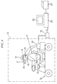
In the first embodiment shown in Fig. 1, a data collector
12 who observes a worker 11 doing a job in a darkroom 10 has
a very small infrared video camera 14, an LCD device 15 and a
microphone 16 on his or her head. The sensitivity of the video
camera 14 is set at an infrared range, i.e., a wavelength range
from about 1000 nm to about 30,000 nm. The LCD device 15 is
so positioned on the head that the data collector 12 may look
up at a screen of the LCD device 15. In order to prevent leakage
of back-light of the LCD display 15, the data collector 12 wears
a pair of darkroom goggles 17 over the LCD display 15. The
darkroom goggles 17 are well known in the art, and enable
observing a faint optical image as a light optical image, so
the data collector 12 can observe the job of the worker 11 in
the darkroom 10.
To a forward protruding end of the darkroom goggle 17 is
attached a work environment sensor 18 for measuring illuminance,
noise, temperature, humidity and other environmental factors
in the workplace. The data collector 12 also has an earphone
19 on his or her ear. The infrared video camera 14, the LCD
display 15, the microphone 16, the work environment sensor 18
and the earphone 19 are connected to a portable personal
computer 20 with an image recording function. Besides, a hand
switch board 21 and a biological sensor 22 are connected to this
portable personal computer 20. The data collector 12 carries
the portable personal computer 20 on his or her shoulder.
The LCD display 15 displays pictures as photographed
through the infrared video camera 14 in a real time fashion,
or a list of titles of the job to observe, and a clock. The
microphone 16 is used for entering unlisted job titles as sound
signals. The earphone 19 is for listening to acoustic responses
from the portable personal computer 20 that is generated in
response to some operations on the portable personal computer
20, e.g. an alarm.
The hand switch board 21 is provided with a pointing
device for pointing one of the job titles listed on the LCD
display 15 with a cursor, an enter key for entering the job title
as selected by the cursor, and a signal input button for
inputting a break point signal. Upon the signal input button
is operated, the break point signal is recorded along with video
data of the photographed pictures on a hard disc of the portable
personal computer 20. The break point signal is used as a cueing
signal for cueing up the head of each video data that corresponds
to one job, so the break point signal is a sequential signal
recognizable for video players. For example, a mark or a sound
that is recorded in the screen is used as the break point signal.
Where the sound is used as the break point signal, the break
point signal may be entered through the microphone 16.
The biological sensor 22 is an infrared sensor in this
embodiment, that measures body temperature of the worker 11.
Because the body temperature rises when the job is busy, the
body temperature may be used as a measure of workload on the
worker. The workload affects the degree of fatigue and the
working efficiency of the worker.
In a light room, the data collector takes off the darkroom
goggle 17, and replaces the infrared video camera 14 with a
compact video camera whose sensitivity is set at a wavelength
range of visible rays (about 400 nm to about 700 nm) for ordinary
photography. In that case, the work environment sensor 18 is
separated from the darkroom goggles 17, and is put on the head
or another part of the data collector 12.
Now the operation of the first embodiment will be
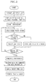
described with reference to the flow chart of Fig. 2. Prior
to the observation, the objects of the observation is specified,
and the fineness of data to observe and other parameters are
predetermined. As concrete exemplary of the objects of the
observation, there would be redesigning the working process,
or changing the number of workers disposed for the same job.
Also the titles of jobs to observe are listed while defining
the titles and classifying them according to some definition,
and the job title list is input in the portable personal computer
20 in advance.
The data collector 12 first puts the portable personal
computer 20 on the shoulder and the LCD display 15 on the head,
and then puts on the darkroom goggle 17. Thereby, the LCD
display 15 is covered with the darkroom goggle 17 in a
light-tight fashion. Next, the data collector 12 puts the
infrared video camera 14 on the head and the earphone 19 on the
ear, and then turns on the portable personal computer 20. While
holding the hand switch board 21 in the hand, the data collector
12 enters the darkroom 10.
In the darkroom 10, the worker 11 is doing a series of
different jobs successively, whereas the data collector 12
observes through the darkroom goggle 17 the worker 11 doing the
jobs, and starts photography by the infrared video camera 14
before the worker 11 starts the series of jobs. Simultaneously
with the start of the initial job of the series, the data
collector 12 inputs a first break point signal by operating the
signal input button on the hand switch board 21.
Thereafter, the data collector 12 looks for the title of
the job photographed at that time while having the job title
list displayed on the LCD display 15. When there is the
corresponding job title in the list, the data collector 12
operates the pointing device on the hand switch board 21 to place
the cursor on that job title, and presses the enter key. Thus,
the job title is recorded along with the video data on the hard
disc of the portable personal computer 20. In this way, the
data collector 12 photographs the jobs by the infrared video
camera 14 while inputting the break point signal and the job
title at each break point between the jobs, till all the jobs
in the series are done. Among the break point signals, special
signals may be used as the first and last ones to represent the
initial and final jobs of the series respectively.
If the corresponding job title is not included in the job
title list on the LCD display 15, the job title is entered as
a sound signal through the microphone 16 at the break point for
that job. The portable personal computer 20 converts the sound
signal representative of the job title into character data and
stores the character data along with the video data. As the
infrared video camera 14 photographs the jobs, the work
environment sensor 18 measures illuminance, noise, temperature
and humidity of the workplace, and enters the measured values
in the portable personal computer 20. The biological sensor
11 feeds data of the body temperature of the worker 11 in the
portable personal computer 20.
In the light room, the infrared video camera 14 is
replaced with the ordinary compact video camera, the darkroom
goggle 17 is taken off, and the work environment sensor 18 is
removed from the darkroom goggle 17 and is put on the head of
the data collector 12. Thereafter, the same operations are
carried out as in the darkroom 10.
After the video data, the break point signals, the job
title data, the work environment data, such as illuminance and
noise, and the workload data are entered as work data with
respect to all the jobs in one series, the portable personal
computer 20 is connected through a cable to a personal computer
25 that is preset for data processing, and the work data is
transferred from the portable personal computer 20 to the data
processing personal computer 25. The work data may be
transferred through a removable memory media, e.g. DVD (Digital
Versatile Disc) and RAM.
The data processing personal computer 25 is used for
monitoring the work data on a display 26, to correct or add
necessary work data items. By retrieving the break point
signals, the work data may be quickly played back at any break
point between the jobs.
Since the time during which the infrared video camera 14
operates is recorded along with the video data in the portable
personal computer 20, the work time taken for each individual
job may be calculated based on the operation time of the infrared
video camera 14. Thereafter, the work data is transformed into
graphs or tables on the display 26, so as to make studies and
analyses about the work data, e.g. about the relationship
between the job content and the workload. If necessary, a hard
copy of the work data is printed out through a printer 27.
It is possible to input the job titles in the data
processing personal computer 25 after the photography is
completed. In that case, the job titles may be entered in the
data processing personal computer 25 through a keyboard or a
bar code reader that is connected to the data processing
personal computer 25 and is combined with a previously prepared
bar code sheet having a plurality of bar codes representative
of the job titles. This configuration permits recording the
job titles while monitoring the photographed pictures, so it
is applicable to those cases where there are a large number of
different kinds of jobs, or the contents of the jobs are
difficult to recognize or discriminate, or it is difficult to
select and enter the job title while observing the job, for
example where the work time for the job is very short.
It is also possible to record the video data in an ordinary
digital video recorder instead of the portable personal
computer. In that case, the break point signals are also
recorded on the memory medium incorporated into or attached to
the digital video recorder.
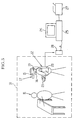
Fig. 3 shows a second embodiment where a worker doubles
as a work data collector 30, and carries the same devices,
including the infrared video camera 14, the LCD display 15 and
the portable personal computer 20, as the data collector 12 in
the first embodiment. In that case, a sensor for measuring
perspiration may be used as the biological sensor 22, in
addition to or instead of the body temperature sensor that is
used for measuring the body temperature of the worker or work
data collector 30.
Where the data collector 12 is supposed to move around
on a small electric car 32, a personal computer 35 installed
in the car 32 may be used in place of the portable personal
computer 20. It is possible to carry a video camera with a
higher performance on the car instead of the compact video
camera 14 on the head. It is also possible to use an automatic
vehicle that carries the personal computer and other machines
and moves along with the data collector 12. In the first and
the present and following embodiments, the data collector may
collect the work data in those workplaces where a plurality of
workers cooperate. Also, in the following embodiments, the
workers themselves can double as the work data collectors, like
in the second embodiment.
Fig. 5 shows an embodiment where the video camera is not
utilized. In this embodiment, the data collector 12 observes
the worker 11 doing the job in the darkroom 10, and looks for
the title of the job on the job title list displayed on the LCD
display 15. When the corresponding job title is found in the
list, the data collector 12 operates the hand switch board 21
to place the cursor on that job title, and presses the enter
key. Thus, at the start of each job, the job title is recorded
on a hard disc or another memory device of the portable personal
computer 20 along with start time data representative of the
time of starting the job.
At the conclusion of each job, the data collector 12
presses the enter key while placing the cursor on the
corresponding job title. Then, end time data representative
of the time of finishing the job is recorded along with the job
title on the memory device of the portable personal computer
20. Where a plurality of different kinds of jobs are to be
carried out in succession, the sequence of doing the respective
jobs is previously checked out, and the job title of the next
job is entered at the break point.
If the corresponding job title is not included in the job
title list on the LCD display 15, the job title is entered as
a sound signal through the microphone 16. In the light room,
the data collector 12 takes off the darkroom goggle 17 and makes
the same operation as in the darkroom 10.
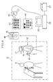
In another embodiment shown in Fig. 6, the data collector
12 uses a sound recording player 40 in place of the portable
personal computer 20. When the data collector 12 tells a job
title to the microphone 16 at the start and the end of one job,
the job title is recorded on a memory of the sound recording
player 40 along with the time when the job title is recorded.
The sound recording player 40 may displays the recorded time
on an LCD panel 41 when the sound recording player 40 plays back
the voice telling the corresponding job title.
After the job tiles of all jobs to observe are recorded
in the sound recording player 40 at respective break points
between the jobs, an operator enters job title data and break
point time data in the data processing personal computer 25 by
use of previously prepared bar code sheets 43 and 44 and a bar
code reader 45 that is connected to the data processing personal
computer 25. The bar code sheet 43 has bar codes representative
of different job titles, whereas the bar code sheet 44 has bar
codes for entering the time data. While playing back the sound
recording player 40 and listening to the job title from the
speaker of the sound recording player 40, the operator enters
the job title by scanning a corresponding one of the bar codes
on the bar code sheet 43 with the bar code reader 45. The
operator also enters the break point time data by scanning those
bar codes on the bar code sheet 44 with the bar code reader 45,
which correspond to the job starting time displayed on the LCD
panel 41.
Fig. 7 shows an example of the bar code sheet 44, that
has bar codes 44a and 44b for discriminating between the job
starting time and the job end time, bar codes 44c, 44d, 44e,
44f, 44g, 44h, 44i, 44j, 44k and 44l representative of numbers
"1" to "9" respectively, and bar codes 44m, 44n and 44o
representative of "hour", "minute" and "second" respectively.
For instance, where the displayed time is "10:15:28", and it
represents a starting time of one job, the operator first scans
the bar code 44a to label the time data as job starting time
data, and then seriatim scans the bar code 44d, the bar code
44c and the bar code 44m to enter the hour "10". Thereafter,
the operator scans the bar code 44d, the bar code 44h and the
bar code 44n to enter the minute "15", and then scans the bar
code 44e, the bar code 44k and the bar code 44o to enter the
second "28".
The bar code reader 45 may be a code-less type. In that
case, data is transferred from the bar code reader 45 to the
data processing personal computer 25 after the completion of
scanning, by connecting the bar code reader 45 to the data
processing personal computer 25 through a cable, or by use of
infrared communication. It is also possible to use a signal
collector that is previously connected to the data processing
personal computer 25, and reads the work data from the bar code
reader 45 automatically or upon a button operation when the bar
code reader 45 is put on the signal connector, to transfer the
work data to the data processing personal computer 25.
Instead of using the bar code sheet, it is possible to
display the job titles on the display 22 of the data processing
personal computer 25, for selecting appropriate ones from these
job titles by means of a touch panel device or through the
keyboard connected to the data processing personal computer 25.
The same data collecting method as shown in Fig. 6 is applicable
to work data collection in the light room, though the data
collector does not use the darkroom goggles 17 in the light room.
It is alternatively possible to use different data
collection methods for the darkroom and the light room. That
is, work data is collected in the darkroom according to the
embodiment shown in Fig. 6, using the sound recording player
40. In the light room, on the other hand, the data collector
scans appropriate bar codes on the bar code sheet 43 at each
break point between the jobs while observing the jobs. In that
case, the bar code reader has a built-in clock, so the time when
the bar code is scanned is recorded along with the corresponding
work data. Thereby, the work data collected in the light room
is transferred from the bar code reader to the data processing
personal computer 25 through a connection wire or cable,
infrared communication or the signal collecting device. So the
labor for entering the work data in the data processing personal
computer 25 is reduced as for the data collected in the light
room.
In a further embodiment of the invention as shown in Fig.
8, the work data is collected in through a sound recording player
50 in the same way as described with respect to the embodiment
shown in Fig. 6, but the sound recording player 50 is connected
to the data processing personal computer 25 through a cable,
to transfer the voice data of the job titles and the time data
of the break points to the data processing personal computer
25. The transferred voice data is converted into character data
through an appropriate function that is provided in the data
processing personal computer 25, e.g. an application package.
This method is used for the light room. It is possible to
transfer the data from the sound recording player 50 to the data
processing personal computer 25 through infrared communication
or other device than the cable.
According to another embodiment a portable personal
computer with an interactive voice response system is used,
wherein the data collector says a job title "X" to a microphone,
then the portable personal computer retrieves the job title "X"
from a job title list that is entered previously. If there is
the job title "X" in the job title list, the portable personal
computer repeats the job title "X" . The data collector listens
to the repeated voice from the portable personal computer
through an earphone. When the data collector answers "YES"
reply to the repeated voice at the start of each job, the job
title is recorded as character data in a memory device of the
portable personal computer, and the time when the job title "X"
is recorded is concurrently recorded as time data of a break
point.
If the said job title "X" is not registered in the job
title list, the portable personal computer responds "The job
title X is unlisted. Register the job title X ?" through the
earphone. If the data collector says "YES" in reply, the job
title "X" is added to the job title list. Thereafter when the
data collector says the job title "X" again, the portable
personal computer repeats the job title "X" then, so the data
collector may answer "YES" at the start of that job, to let the
personal computer store the job title "X" in the memory device
along with the time data of that break point. Since the job
titles are recorded after being confirmed in this embodiment,
data input error is prevented. The same method is applicable
to collecting work data in the light room. Because this
embodiment may be illustrated approximately equivalently to Fig.
1, this embodiment is not illustrated in the drawings.
In an alternative, the data collector says a job title
to record the job title in the sound recording player through
the microphone, and thereafter turns on a voice switch of a voice
clock at a break point between the jobs, to cause the voice clock
to generate a voice saying the time of that break point, for
recording the voice from the voice clock in the sound recording
player through the microphone. It is possible to record the
time of the break point prior to the job title.
Next, an embodiment shown in Fig. 9 will be described.
In this embodiment, a worker 11 is equipped with more than one
biological sensor, i.e. three biological sensors 63, 64 and 65
on the head, on the back of his or her hand and on the hip in
the illustrated example. Output signals from the biological
sensors 63 to 65 are entered through a radio communication
device 66, e.g. a blue tooth, into a portable personal computer
20. In that case, the portable personal computer 20 is equipped
with a counterpart radio communication device to the radio
communication device 66.
On the other hand, a data collector 12 to observe the
worker 11 doing jobs has a work environment sensor 18, a very
small video camera 69 and a goggle 70 on his or her head in a
work area 68. An LCD display 15 is mounted inside the goggle
70, such that the data collector can look up the screen of the
LCD display 15. The work environment sensor 18 may be put on
the worker 11 or disposed on any appropriate locations in the
work area 68, besides the data collector 12. In that case, the
work environment sensor 18 remote from the data collector 12
is connected through a communication device to the portable
personal computer 20. Like or equivalent elements are
designated by the same reference numbers as used in the above
embodiments, and the description of these elements are omitted.
For example, the biological sensors 63 to 65 are
acceleration sensors that quantitatively determine the degree
of workload on the basis of movements or physical displacements
of the worker's head, hand and hip. Although the worker puts
on only three biological sensors in the embodiment of Fig. 9,
this is only for the sake of simplifying the explanation and
the illustration. In practice, it is desirable for the worker
to put as many biological sensors as possible on his or her body,
e.g. on the shoulder, elbow, knee, ankle and so forth.
Besides the acceleration sensors, the biological sensors
may be well-known gyroscopes or relative position sensors that
use magnetic wave or electronic wave. A magnetic sensor for
detecting relative positions of respective portions of the
worker's body, or illumination sensor for measuring illuminance
of the field of view may also be used as the biological sensor.
According to the purpose, it is possible to use a sensor for
measuring myogenic potential, pulses, heart beats, or brain
wave. Besides the illuminance sensor, it is possible to use
a temperature sensor, humidity sensor, gas density sensor or
sound volume sensor. As for the infrared sensor that measures
the body temperature, it is carried by the data collector to
measure the body temperature of the remote worker. To measure
the body temperature at different portions of the worker, a
plurality of thermometers are put on the respective portions
of the worker.
As the biological sensor, it is also possible to put a
CCD camera with a super wide angle lens on the top of the worker
while directing the camera upward, to calculate the direction
of movement of the worker's head and the change of the direction
quantitatively on the basis of image data picked up through the
CCD camera. By use of data from the acceleration sensors on
the worker's hand, leg and corporal portion, and data from a
sensor detecting distances between these acceleration sensors,
it is possible to obtain data showing the movement of the
worker's body as a total, the movement of the worker's hands,
the movement of the worker's legs, and which portions of the
worker's body are overused.
It is known in the art that the number of blinks and winks
of the worker, the movement of the eyeballs, the variation in
worker's expression, the amount of movement of worker's gaze,
and variation in brightness in the direction the worker is
looking may be used as properties representative of worker's
thinking and attention. Accordingly, it is possible to
quantify data of these representative properties by
photographing worker's face through a video camera.
It is also possible to provide specific marks on worker's
hand, work, note book or the like, for recording whether these
marks are included in designated positions in the image screen
that corresponds to the field of view of the worker. Thereby,
it becomes possible to record the frequency of worker's
movements to look at a range around his or her hand during the
respective job.
Furthermore, by providing sound volume sensors on
worker's head and in the vicinity of worker's mouth, it is
possible to obtain data of worker's voice and ambient sounds
separately from each other, and check if any conversation is
always held in the job. It is preferable to use such a data
input device for the biological sensors that permits obtaining
data from the worker without the need for contact with the worker,
in view of the advantages that such sensors are easy to put on
and take off, that data becomes less dependent on the wearing
conditions of the sensors, and that mental pressure on the
worker or invasion of worker's privacy from wearing the sensors
are reduced. It is possible to use these non-contact type
sensors in combination with contact type sensors, such as the
myogenic potential sensor.
Data from the biological sensors 63 to 65 is stored in
the hard disc of the portable personal computer 20 as
attribution data for the respective jobs which are sectioned
by the break point signals . It is possible to previously define
judgement logic for comparison with threshold values and
patterns that represent the degree and characteristics of the
load, and stores the judgement data concurrently with the
storage. For example, a preliminary observation is carried out
once without setting any time limit for each job, and maximum
values of the data obtained from the biological sensors on the
respective jobs are defined to be the threshold values. If the
data obtained in the observation on the actual job goes above
the threshold value of that job, judgement data may be stored
showing that the time limit for that job results a higher
workload.
Now the operation of the embodiment shown in Fig. 9 will
be described with reference to the flowchart of Fig. 10.
Prior to the observation, the objects of the observation
is specified, and the fineness of data to observe and other
parameters are predetermined. As concrete exemplary of the
objects of the observation, there would be redesigning the
working process, or changing the number of workers disposed for
the same job. Also the titles of jobs to observe are listed
while defining the titles and classifying them according to some
definition, and the job title list is input in the portable
personal computer 20 in advance. In addition, according to the
purpose of the analysis, it is determined what kinds of
biological sensors and environment sensors should be used, what
the purpose of obtaining the data, how much sensors should be
placed in which locations, and how to process the data, and the
portable personal computer 20 is preset correspondingly.
The data collector 12 first puts the portable personal
computer 20 on the shoulder and the LCD display 15 on the head,
and then puts on the darkroom goggle 17. Thereby, the LCD
display 15 is covered with the darkroom goggle 17 in a
light-tight fashion. Next, the data collector 12 puts the
infrared video camera 14 on the head and the earphone 19 on the
ear, and then turns on the portable personal computer 20. While
holding the hand switch board 21 in the hand, the data collector
12 enters the darkroom 10.
The data collector 12 observes the worker 11 doing a
series of different kinds of jobs, and starts photography by
the video camera 69 before the worker 11 starts the series of
jobs. Simultaneously with the start of the initial job of the
series, the data collector 12 inputs a first break point signal
by operating a signal input button on a hand switch board 21.
Thereafter, the data collector 12 looks for the title of
the job photographed at that time while having the job title
list displayed on the LCD display 15. When there is the
corresponding job title in the list, the data collector 12
operates the pointing device on the hand switch board 21 to place
the cursor on that job title, and presses the enter key. Thus,
the job title is recorded along with the video data on the hard
disc of the portable personal computer 20. In this way, the
data collector 12 photographs the jobs by the infrared video
camera 14 while inputting the break point signal and the job
title at each break point between the jobs, till all the jobs
in the series are done.
If the corresponding job title is not included in the job
title list on the LCD display 15, the job title is entered as
a sound signal through a microphone 16 at the break point for
that job. The portable personal computer 20 converts the sound
signal representative of the job title into character data and
stores the character data along with the video data. As the
video camera 69 photographs the jobs, the work environment
sensor 18 measures illuminance, noise, temperature and humidity
of the workplace, and enters the measured values in the portable
personal computer 20. The biological sensors 63 to 65 supply
the portable personal computer 20 with data of the body
temperature of the worker 11, data of movements of the worker's
head, hand and hip, and data obtained through the load judgement
logic.
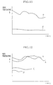
As exemplary of the workload data, temperature data
detected through an infrared sensor includes prime data α and
β, as shown in Fig. 11, both showing changes in worker's body
temperature with time during a job "A", but measured under
different conditions, e.g. a large restriction on time is
imposed in one case, whereas the time restriction is not so hard
in the other case. The temperature data also include prime data
that show changes in worker's body temperature with time during
each of different jobs A, B, C and D, as shown in Fig. 12. As
for the data of relative positions of the respective body
portions, that is detected for example through a magnetic sensor,
or the data of displacement of the respective body portions,
that is detected through the acceleration sensors, prime data
representative of amounts of displacement in a time section for
each job, e.g. variations in position and inclination to front,
rear, left, right, up and down, and mean values and maximum
values of the displacements are stored. Where the workload data
is illuminance data in the direction of view field, prime data
representative of changes in illuminance with time during each
individual job and mean values as well as maximum values are
stored. If a sensor measuring the blinks and winks or the
movement of the eyeballs through a camera is used as the
biological sensor, variations in blinking timing, in the number
of blinks and in the time interval of blinks during each job
are stored as workload data.
After the completion of the observation on the jobs, the
portable personal computer 20 is connected through a cable to
a personal computer 25 for data processing, for transferring
the work data from the portable personal computer 20 to the data
processing personal computer 25. The work data may be
transferred through a removable memory media, e.g. DVD or RAM.
The data processing personal computer 25 transforms the work
data into graphs or tables and displays the graph or table on
the display 26, so as to make studies and analyses about the
work time and workload for each job. If necessary, a hard copy
of the work data is printed out through a printer 27.
For analysis of the work data, the work data is tallied
up for the respective jobs in a process, and the content of each
job is analyzed. In the analysis for each job, it is usual for
the analysis with the job title and time to use tables in which
a mean time, a total time and a ratio to the total time are
obtained for each job title, and a Pareto diagram in which the
job titles are arranged in a sequence from the longest total
time, as shown in Fig. 13. By displaying a graph showing the
workload data, as shown in Fig. 14, in addition to the graph
of Fig. 13, it is possible to show characteristics of the process
and get priorities right for improvement in working conditions
with respect to each job. According to the example shown in
Figs. 13 and 14, the job titled "A" is largely affected by the
time restriction, and the illuminance in the direction of the
view field is high for a longest time in this job. That is,
the job "A" is to input data while staring in a CRT display with
a relatively high brightness, and thus the workload is very high.
On the contrary, the job "B" is not largely affected by the time
restriction, and the total work time is short, through the
illuminance in the direction of the view field is high.
Therefore, the workload of the job "B" in total may be considered
to be relatively low.
For analysis of job sharing and timing, it is usual to
display the contents of jobs in a time sequential fashion in
the form of a man-machine chart or Gantt chart, as shown in Fig.
15. By displaying a chart showing the workload data obtained
by the length of high illuminance time period in the view field
direction, as shown in Fig. 16, in addition to the Gantt chart,
it is possible to show the viewpoints for improvement in the
job sequence and shares. In these charts, the time is the work
time, and the total work time is 8 hours in this instance.
According to the data analysis based on the charts shown
in Figs. 15 and 16, a worker W1 does a constant speed job, a
job to be done at an approximately constant speed, in a process
with heavy restriction of time, so the workload is highly
dependent upon time. Since the high illuminant time in the view
field direction is short, the worker's attention or carefulness
is also dependent upon time. On the other hand, a worker W2
is less affected by the time restriction, but the workload on
the eyes may be judged to be large in view of the data of
illuminance in the view field direction. The worker W2 is
presumed to be in charge of a job that requires the worker to
stare in a bright object, like a display or an inspection box
(Schaukasten).
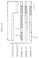
Furthermore, by entering those data in the PERT (Program
Evolution And Review Technique) software that represents
restrictions applied by installations onto the movement and the
sequence of jobs, so as to display workload conditions in
combination, as shown in Fig. 17, it is possible to provide a
Gantt chart showing the offset in work time or in workload as
the results of job allocation in the process. In Fig. 17,
hatched sections 75 represent jobs with relatively high workload,
dotted sections 76 represent jobs with relatively low workload,
and blank sections 77 represent standby state.
In the illustrated example, the worker W1, W2 and W3 do
the respective jobs in an installation E during the first two
third and more of a total work time T1, and then in another
installation F almost during the last one third of the total
work time T1. The worker W1 is busy working through the total
work time T1. The worker W2 is in the standby state in the first
half of the total work time T1, and starts a job with a low
workload from the last half of the job in the installation E,
and gets busy after shifting to the job in the installation F,
but comes into the standby state in the last half of the job
in the installation F. The worker W3 is in an easy condition
with the standby state and the easy job during the job in the
illustration A, but gets busy immediately before shifting to
the installation F, and then comes to the standby state in the
last half of the job in the installation F. In view of this
situation, it is easy to think of an improvement that the worker
W2 and W3 whose workloads have been very low can share the job
of the worker W1 at least in the first half of the total work
time T1. In this example, the total work time T1 is one hour.
By use of the workload data and dividing the jobs into
several segments, it is also possible to express the
characteristics of the process by the number of jobs and the
total time in each segment. For example, standards for
discrimination between large, middle and small values of the
workload data about each job are determined to sort the data
for each job. It is also possible to divide the data into
segments by combining the data with one another, or rank the
jobs by use of total indexes that are obtained by weighting the
load data. Analyzing the job in this way makes it easy to find
out those jobs which should be inspected and improved.
The following Table 1 shows the ranking of jobs P, Q, R
and S in view of the workload, along with the work time ratio
and the frequency. Table 2 and Table 3 show the work time ratio
and the frequency of the workloads of the respective ranks, with
respect to different workers W1 and W2.
| JOB | P | Q | R | S |
| INFLUENCE OF TIME RESTRICTION | LARGE | LARGE | MIDDLE | MIDDLE |
| LOAD ON EYES | LARGE | MIDDLE | MIDDLE | SMALL |
| MOVEMENT OF EYEBALLS | LARGE | MIDDLE | MIDDLE | MIDDLE |
| MOVEMENT OF WORKER | SMALL | LARGE | MIDDLE | MIDDLE |
| MOVEMENT OF WORKER'S HAND | LARGE | LARGE | MIDDLE | SMALL |
| WORK TIME | 100 | 90 | 50 | 40 |
| FREQUENCY | 4 | 2 | 7 | 3 |
| TOTAL INDEX | 90 | 40 | 35 | 15 |
| [WORKER W1] |
| INFLUENCE OF TIME RESTRICTION | LARGE | MIDDLE | SMALL |
| LOAD ON EYES | L | M | S | L | M | S | L | M | S |
| WORK TIME | 100 | 80 | 60 | 50 | 250 | 300 | 30 | 500 | 600 |
| FREQUENCY | 2 | 4 | 2 | 5 | 25 | 10 | 20 | 50 | 60 |
| [WORKER W2] |
| INFLUENCE OF TIME RESTRICTION | LARGE | MIDDLE | SMALL |
| LOAD ON EYES | L | M | S | L | M | S | L | M | S |
| WORK TIME | 0 | 60 | 60 | 10 | 50 | 30 | 10 | 900 | 600 |
| FREQUENCY | 0 | 1 | 2 | 5 | 25 | 10 | 20 | 10 | 60 |
In this way, characteristics of the job may be compared
and analyzed with respect to each process or with respect to
each worker, for the sake of distributing or equalizing the
workload on the workers, or examining how to assign the jobs
to the workers according to their skills, or setting goals for
improvement in job quality.
For instance, because the data is previously sectioned
by each job in Table 1, it is easy to pick up only those data
which relate to the aimed job from among the data of all jobs.
If there are a plurality of data pieces for the same job title,
these data pieces may be compared to each other or tallied up.
For example, for such job where the workload vary at each
execution, it becomes possible to restructure the job
procedures to stabilize the workload.
As for those jobs which are determined to be aimed at by
the statistic analysis of the data on the above all jobs, more
detailed analysis of the data on each of these jobs is useful
for examining the object. For example, as for the job P in Table
1, the starting time, the ending time, the requisite time
duration, changes or progresses in movements of respective
portions of the worker's body, direction of the movements, mean
values and maximum values of the moved amounts, changes with
time in illuminance in the view field direction, a mean value
and a maximum value of the illuminance, changes with time in
body temperature in the view field direction, a mean value and
a maximum value of the body temperature, and other data are shown
in a lookup table. Based on the lookup table, it is possible
to analyze how the workloads in the job P affect the worker,
and find out necessary points for improvements in the facilities
or in the working method, including job collaboration.
Specifically, it becomes possible to eliminate, combine,
rearrange and simplify the jobs by optimizing load allocation
during the work time and among respective workers in a
collective work, by optimizing job allocation to unskilled
workers, by extracting problems in calculating wages per unit
job, in frequency of the workload, and in the progress of the
workload with time, and by applying such viewpoints for
improvement that is a kind of Industrial Engineering (IE) to
examining the workloads.
Fig. 18 shows a modification of the embodiment as set
forth above with reference to Figs. 9 to 17, wherein the data
collector is not disposed in the work area 68, but a worker
doubles as a data collector 30, carrying the video camera 69,
the biological sensors 63 to 65 and other devices necessary for
data collection on his or her own body. This embodiment
contributes to saving labor for data collection.
Although the break point signal is entered by means of
the hand switch board in the above embodiment, it is possible
to predetermine the break point as a time when a particular mark
comes in the view field, or by a particular sound from an
installation during the process, so that the break point signal
may be automatically entered. This embodiment allows to
substitute a robot or the like for the data collector 12.
It is not always necessary to actuate the environment
sensor and the biological sensors in cooperation with the video
camera, but these sensors may operate independently. Although
the workload is measured through the biological sensor in the
above embodiments, the data collector may judge the degree of
the workload on the worker from the observation, and input the
degree of the workload through an appropriate data input device,
such as a bar code reader in the workplace or while observing
the photographed video pictures afterward. In the latter case,
another person may judge the degree of the workload instead of
the data collector.
As the video camera for the darkroom, a high-sensitive
video camera like an image intensifier camera is usable instead
of the infrared video camera. By attaching a special filter
that changes the sensitive wavelength range of the video camera,
or by using a special video camera that may switch the sensitive
range between the infrared range and the visible light range,
the same video camera may be used both for the darkroom and the
light room.
In the above embodiments, the memory medium of the sound
recording player is a high-speed accessible memory. But a hard
disc or a recording tape or MD (Mini Disc) is usable instead.
The present invention is applicable to those cases where the
worker deals with chemical products or the like, if only the
portable personal computer or sound recording player and other
apparatuses as used in the darkroom in the above embodiments
are provided with waterproof functions. The present invention
is applicable not only to the above described observation on
working conditions, but also to recording and analyzing the
present conditions or modifications of the equipment in a
darkroom. It is also possible to apply the present invention
to worker's daily report, recording of worker's movement,
recording and analyzing a conference or meeting.