US4413277A - Instant replay productivity motivation system - Google Patents
Instant replay productivity motivation system Download PDFInfo
- Publication number
- US4413277A US4413277A US06/227,600 US22760081A US4413277A US 4413277 A US4413277 A US 4413277A US 22760081 A US22760081 A US 22760081A US 4413277 A US4413277 A US 4413277A
- Authority
- US
- United States
- Prior art keywords
- operator
- display
- work
- time
- relating
- Prior art date
- Legal status (The legal status is an assumption and is not a legal conclusion. Google has not performed a legal analysis and makes no representation as to the accuracy of the status listed.)
- Expired - Fee Related
Links
Images


Classifications
-
- G—PHYSICS
- G09—EDUCATION; CRYPTOGRAPHY; DISPLAY; ADVERTISING; SEALS
- G09B—EDUCATIONAL OR DEMONSTRATION APPLIANCES; APPLIANCES FOR TEACHING, OR COMMUNICATING WITH, THE BLIND, DEAF OR MUTE; MODELS; PLANETARIA; GLOBES; MAPS; DIAGRAMS
- G09B19/00—Teaching not covered by other main groups of this subclass
- G09B19/003—Repetitive work cycles; Sequence of movements
- G09B19/0038—Sports
-
- G—PHYSICS
- G06—COMPUTING; CALCULATING OR COUNTING
- G06Q—INFORMATION AND COMMUNICATION TECHNOLOGY [ICT] SPECIALLY ADAPTED FOR ADMINISTRATIVE, COMMERCIAL, FINANCIAL, MANAGERIAL OR SUPERVISORY PURPOSES; SYSTEMS OR METHODS SPECIALLY ADAPTED FOR ADMINISTRATIVE, COMMERCIAL, FINANCIAL, MANAGERIAL OR SUPERVISORY PURPOSES, NOT OTHERWISE PROVIDED FOR
- G06Q10/00—Administration; Management
- G06Q10/06—Resources, workflows, human or project management; Enterprise or organisation planning; Enterprise or organisation modelling
- G06Q10/063—Operations research, analysis or management
- G06Q10/0639—Performance analysis of employees; Performance analysis of enterprise or organisation operations
- G06Q10/06398—Performance of employee with respect to a job function
-
- G—PHYSICS
- G09—EDUCATION; CRYPTOGRAPHY; DISPLAY; ADVERTISING; SEALS
- G09B—EDUCATIONAL OR DEMONSTRATION APPLIANCES; APPLIANCES FOR TEACHING, OR COMMUNICATING WITH, THE BLIND, DEAF OR MUTE; MODELS; PLANETARIA; GLOBES; MAPS; DIAGRAMS
- G09B5/00—Electrically-operated educational appliances
- G09B5/06—Electrically-operated educational appliances with both visual and audible presentation of the material to be studied
- G09B5/065—Combinations of audio and video presentations, e.g. videotapes, videodiscs, television systems
Definitions
- the present invention relates to the field of industrial engineering, and more specifically, to the particular facet of that field dealing with the time-motion analysis of work functions in which an operator performs the same task, comprising one or more manipulative steps, over a substantial period of time.
- the engineer For example, if the engineer is conducting a time study of an operator who is sewing pockets on shirts, he might record the time it took the operator to carry out each of the steps of picking up a pocket and shirt to be sewn, aligning the pocket in the proper location on the shirt, stitching each of the various edges of the pocket, and disposing of the finished shirt.
- the engineer Once the engineer had measured a number of operations over a particular length of time, e.g., one hour, the engineer would then return to his office where he would calculate the results of the measurements he had just taken. Typically, the calculation would require at least another hour of the engineer's time, and could take as much as three to four hours.
- Another problem that is faced by the industrial engineer relates to the credibility that the operator is willing to give to the results obtained by the engineer. For example, as a result of his study, the engineer might determine that the operator's time for a particular step is longer than the standard time based on an average of all observed workers. He further might suggest to the operator that if the operator were to decrease his time on this step, he would be able to process a greater number of garments per day, and thus would set the operator's daily quota at this figure. However, the operator may not be willing to accept the determinations and suggestions given by the engineer. For example, he may think that the engineer was not operating the stopwatch at the correct times and therefore is not willing to place any weight on the numbers generated as a result of the engineer's study. Furthermore, he may consider the engineer's suggestion of a production quota to be too subjective, and thus might feel that it is unfair.
- the operator might ask the Engineer how his performance rated.
- the engineer due to the time required by the engineer to calculate the results of his measurements before he can present them to the operator, he cannot immediately answer the operator's question.
- the operator may have lost interest in the purpose of the study, or the style of the garment may have changed to such a degree that the results of the study are no longer applicable.
- the calculated results are communicated to the operator in a visual and personalized manner such that the operator can readily understand the factors that are of concern to the industrial engineer, accept the results of the study, gain useful insights into self-improvement and effectively participate in the determination of his quota.
- Video systems have been used in the past as a training tool.
- a recording is made of operators performing a task for which others are to be trained.
- the recording is made, for example on video tape, it is usually edited, and further processed to provide titles, graphical data, etc.
- This editing and processing step usually results in the expiration of a substantial amount of time between the recording of the operators performance and its subsequent playback.
- this conventional type of video teaching system may have some value in the training of new operators, but generally is not useful as an analysis tool in the time study environment, because it does not operate on a real time basis.
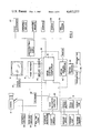
- FIG. 1 is a block diagram of the major components of a preferred embodiment of a time-motion analysis system constructed in accordance with the present invention
- FIG. 2 is a view of a video display screen illustrating the various types of information that can be presented on the output display of the system;
- FIG. 3 is a detailed view of the video camera illustrating the switches that can be used to manually provide input signals to the system
- FIGS. 4-8 are illustrations of the video display screen illustrating specific examples of calculated information that can be presented to the operator and the observer in a useful fashion during the feedback mode of operation of the system.
- the basic components of a time-motion analysis system constructed in accordance with the present invention are illustrated in the block diagram of FIG. 1.
- the primary input channel of the video system includes a video camera 10 and video tape recorder 12 that the industrial engineer, or observer, uses during the course of his time study to visually record the motions of the operator being studied.
- the video tape recorder 12 is connected to a video monitor 14 that comprises the basic output element of the system.
- Another input channel of the analysis system comprises a timer assembly, or real time clock, 16 that operates in conjunction with a character generator in a computer system 18.
- the clock 16 and the character generator can both comprise integral units of the computer system 18, that is used to control the various internal operations of the system and provide desired calculations.
- the computer system can be comprised of a central control computer 19 and one or more dedicated computers 20 and 20' that primarily function as interface units for processing and controlling the flow of information between the central computer 19 and various pieces of peripheral input and output equipment.
- the computer 19 receives real time information from the timer assembly 16 and generates one or more displays related to the real time information on the screen of the monitor 14 through a video mixer 21, as well as causes them to be recorded in the video tape recorder 12, and simultaneously within the memory of the computer system 18.
- a replay module 23 includes an encoder that numbers each video picture, or field, individually, and records numbers on the video tape and in the computer memory in conjunction with the real time data of the current work element, or cycle. This information enables the computer to search and find, in a random access mode, any point in the study without rewinding the tape to the starting point.
- the manual input of information by the observer or the operator into the system can be accomplished through a conventional alpha-numeric keyboard unit 22 associated with the microprocessor.
- a separate manual input unit comprising a limited number of switches associated with particular facets of the study, i.e., stopwatch control, is provided.
- the stopwatch control switches 24 are preferably provided on the pistol grip handle of the camera for convenient access.
- the stopwatch control switches 24 can be located on a separate control unit.
- the system can also be provided with a touch screen input module 25 to manually enter information.
- control functions for example rewind, fast forward, etc., relating to the recorder 12, are displayed on the screen of the monitor 14, and by simply touching the screen at the place where the function is displayed, the control function will be carried out. This form of input is particularly useful during interactive feedback with the operator.
- the analysis system can also be provided with a voice recognition module 26 by means of which certain predetermined control words can be audibly entered into the system.
- a tone or voice synthesizer 27 can be provided, either as a separate unit or in combination with the voice recognition module 26, to give the system the capability of providing audible output signals.
- pace display control unit 30 Another input element is a pace display control unit 30.
- the pace display control unit 30 enables the observer to display his estimate the worker's pace on the monitor 14 and have it simultaneously recorded by the video recorder 12 and within the memory of the computer system.
- the pace display control unit 30 comprises a slider switch that controls the position of an indicator on the screen of the monitor 14 with respect to a scale indicating units of working pace, such as percentage values, for example.
- the system can also be provided with a hard copy printer 28 for providing an alpha-numeric printout of predetermined data useful for subsequent studies.
- the analyzer system can also be provided with sensory inputs related to the elemental work steps that can be automatically sensed, such as machine implemented steps.
- the analyzer system can also be provided with sensory inputs related to the elemental work steps that can be automatically sensed, such as machine implemented steps.
- one or more sensors 31 can be placed on the sewing machine to provide an indication related to the time it takes each portion of the sewing step to be completed. More specifically, sensors can be provided on the machine to indicate movement of the needle, position of the presser foot, direction of material feed through the machine, and machine speed.
- discrete motion sensors or transponders 33 could be placed on the operator's hands or fingers, for example, and a sensory field set up by means of transmitters 35 to detect the operator's individual hand movements during performance of the various steps.
- the detected movements can provide input information relating to the distance, direction, time required for each movement, or delays between movements, and recorded in the computer system memory. Appropriate displays relating to the detected motions can be generated on the video monitor.
- FIG. 2 comprises an illustration of the display screen of the video monitor 14.
- the observer loads appropriate programs into the computer system 18 along with the data necessary for the particular study to be undertaken.
- the program information can be entered on a magnetic disk that is inserted into a disk drive and read unit 32 (FIG. 1) associated with the computer 19.
- the various types of information entered into the system include the names, or labels, and sequence of each of the manipulative steps to be carried out by the operator during the performance of each task.
- the various elemental steps of that task can include (1) picking up a pocket and a shirt, (2) positioning the shirt on the sewing machine and aligning the pocket on the shirt, (3) sewing the first seam on the pocket, (4) repositioning the shirt, (5) sewing the second seam on the pocket, (6) repositioning the shirt, (7) sewing the third seam on the pocket, (8) clipping the thread, and (9) disposing of the finished shirt.
- the input data to the system can include a listing of the various types of interruptions that might occur during the performance of an operator's task. Examples of such types of interruption include occurrences such as the breaking of a needle or thread, wrong color fabric, the trimming of a piece of fabric, or stopping to talk to a fellow worker who passes by.
- a library of the labels associated with each of the various types of interruptions is preferably stored in that part of the system along with the necessary information relating to the observer's audible statement of each label.
- Other types of data that are fed into the system prior to the initiation of the study can include programs relating to the calculation and graphical presentation of data obtained during a study.
- the video camera When the study is initiated, the video camera is focused upon the operator's work station and turned on, causing a live display of the operator at work to appear on the screen 34 of the monitor 14.
- the timer 16 and character generator within the computer cause a display 35 of the actual time, for example in terms of hours, minutes and seconds, to appear near the edge of the screen 34. If desirable, the date and information relating to the operator and work task can be manually entered into the system by means of the microprocessor keyboard 22 and displayed along with the actual time.
- a snapback switch 36 is actuated each time that an elemental step of the work process is completed, and hence the next elemental step begins.
- the cycle switch 38 is actuated by the observer when the final step of a task, e.g., the disposing of a shirt, is completed.
- a totalizing switch 40 is actuated whenever a predetermined number of shirts, e.g., one dozen, have been completed.
- An interrupt switch 42 is actuated each time an interruption, such as a thread break, occurs, to signal the interruption of the elementary step being carried out. The interrupt switch 42 is also actuated when the interruption has terminated, to thereby signal the resumption of the measurement of the elemental step previously being carried out.
- the observer actuates the snapback switch 36 to indicate that the operator is beginning the performance of the first elemental step of his task.
- a display of the label 44 of the elemental step being performed, and its sequence number 46 will be generated along one side of the screen 34.
- a "running time" display 48 of the elapsed time from the actuation of the snapback switch 36 wll appear adjacent the element label 44. This display can be in terms of minutes, seconds, and fractions of a second, and can begin at zero upon actuation of the switch.
- the observer again actuates the snapback switch 36.
- the second actuation of the switch causes the next label 50 and next sequence number 52 of the second elemental step of the task to be displayed on the edge of the screen, for example immediately above the display of the first element label and its running time.
- a running time display 54 associated with the performance of the second step will appear on the screen adjacent the label of the step.
- the time display 48 of the first step freezes, to thereby provide an indication of the amount of time it took for that step to be performed.
- the indication of the elapsed time for that step preferably remains displayed on the screen 34 for a predetermined time period, e.g., two seconds after the completion of the step, so it can be seen later during playback.
- the stopped time display is preferably different color, or a negative of the rolling time display.
- the rolling time display 48 of the first element appears as black digits on a white background
- the actuation of the snapback switch 36 to freeze that time display and to cause the second time display 54 to be initiated would also cause a black box 56 to be generated adjacent the first element label 44, and the elapsed time for the performance of the first elemental step would appear within the box 56 as white digits.
- the operation of the system continues in this fashion, with the observer actuating the snapback switch upon the initiation of each step in the task to thereby cause a new display associated with the new step to be generated and the running time display of the previous step to freeze.
- the actuation of the snapback switch can provide a signal to cause the elapsed time for the completed step to be printed by the printer 28 and stored at an appropriate address in a memory unit 58 (FIG. 1) associated with the microprocessor 20.
- the observer actuates the cycle switch 38.
- a signal from the switch 38 causes the element label 44 and sequence number 46, as well as the running time display 48, of the first elemental step to again be generated, and freezes the time display associated with a last elemental step of the just-completed task.
- actuation of the switch 38 can cause a display 60 of the total time it took to carry out the task, i.e., the sum of the individual elemental times plus any interruptions, to appear at the top of the screen. This information also is printed out by the printer 28 and recorded in the memory unit 58.
- the end of cycle signal from the switch 38 can cause the voice synthesizer in the voice recognition module 26, if so equipped, to audibly announce the completion of the cycle or beginning of a new one, e.g., "Garment No. 34".
- the observer can actuate the totalizer switch 40 rather than the cycle switch 38.
- the signal from the totalizer switch causes all of the same functions to be formed as that from the cycle switch, and in addition, generates another display (not shown) indicating that total time that it took to process all of the shirts in the bundle.
- the cycle switch 38, totalizer switch 40, or both can be eliminated and the computer can automatically carry out the functions of these switches upon actuation of the snapback switch 36 after completion of the last elemental step, since it is programmed with the information relating to number of steps in a cycle, number of shirts in a bundle, etc.
- the observer When an interruption, delay, or other event out of the normal work method occurs during a study, the observer actuates the interrupt switch 42 on the hand control unit. Actuation of this switch causes the running display of the time thus far elapsed on the regular element being performed to be stopped, causes a display 64 associated with the interrupt event to appear on the screen, and starts the timing of the interrupt element. Immediately after the interrupt switch is actuated, the observer announces the label for the interrupt element to identify it to the microprocessor by means of the voice recognition module 26. Upon recognition of the interrupt label, the label is generated adjacent the rolling time display for the interruption.
- the voice synthesizer is actuated to speak the name of the label as a form of feedback to the observer so that he will know that the proper label has been recognized by the computer.
- the observer's voice is also fed into the video tape recorder soundtrack so that it can be heard and played back from the recording. The number of times that this particular interruption has occurred during the course of the cycle, batch, or study can also be displayed adjacent the running time.
- the actuation of the interrupt switch also causes an indicator 66 to be displayed adjacent the elemental work step that was being timed, to serve as a reminder to the observer that he must again press the interrupt switch a second time at the end of the interruption in order to resume the timing of the regular work element.
- the indicator can be made to flash, or the actual display of the element label, sequence number and time can flash, in order to provide a more noticeable indication.
- the interrupt switch 42 is again actuated to stop the running of the time in the interruption display 64 and resume the timing of the elemental work step that was previously being measured.
- the display of the interruption time and its label preferably remains on the screen for a predetermined time period, e.g., two seconds, unless another interruption occurs, which will automatically cause the first interruption display to disappear.
- the label and the time for the interruption, along with the number of the garment and the sequence number of the elemental work step within which it occurred, are preferably stored in the microprocessor memory.
- a vertical scale 68 appears on the left margin of the screen.
- the scale is graduated in suitable units associated with work pace, e.g., percentage values.
- a cursor arrow 70 appears adjacent the screen and indicates the observer's current (or most recent) estimate of the operator's working pace.
- the hand-held pace display control unit 30 enables the observer to vary the position of the cursor or the scale as his estimate of the working pace changes. In order to insure that the observer's evaluation of the working pace is kept current, the cursor can be caused to flash whenever 15 seconds have elapsed since the observer last varied the pace rating.
- the voice synthesizer can be actuated to speak the word "pace" as a means of prompting input from the observer.
- the pace display control unit 30 is peferably provided with an acknowledge switch to enable the observer to indicate that he estimates the operator to be continuing to work at the same pace, and thereby reset the timer for the flashing cursor and the voice synthesizer prompt indicators.
- the cursor 70 can be caused to start flashing each time an interruption occurs, to thereby prompt the observer to note any changes in the operator's working pace that may be caused by the interruption.
- the pace scale 68 that appears on the screen is preferably graduated in steps appropriate to the particular work task being studied.
- the total scale may be divided into a series of scales, only one of which is displayed on the screen at any time.
- a scale having a total range of 50% to 200% can be divided into three scales of 50-100%, 100-150%, and 150-200%. These scales can be overlapping, if desired. Only one of the scales would appear on the screen, and as the cursor approaches the end of that scale, the display would be caused to automatically change over to the adjacent scale, and the position of the cursor adjusted correspondingly.
- each of the various scale breakdowns can be color coded, for example, white for a low pace range, green for a middle range, and red for a fast range.
- white for a low pace range if the operator is initially working at a relatively low rate less than 100%, a white scale would appear on the monitor screen.
- the indication of the scale would change from white to green, thereby providing a readily discernible and useful indication.
- Pictorial illustrations corresponding to each of the automatically sensed operations of the machine can be placed on the video monitor screen 34.
- a picture of a needle 72 can be produced on the screen whenever the needle of the sewing machine is not moving. As soon as the operator starts the needle in motion, the illustration of the needle 72 on the screen will disappear to provide an indication that the machine is in operation.
- a picture of a presser foot 74 can be produced on the screen each time that the presser foot is in the raised position, and disappear when the operator lowers it into contact with the material for machine operation. Arrows 76 can be produced on the screen to illustrate the direction of material feed through the machine during operation.
- suitable displays of elapsed time between the various sensed operations can also be produced on the screen.
- an indication of the time delay between the lowering of the presser foot and the initiation of sewing i.e., the time difference between the disappearance of the indication of the presser foot 74 and the disappearance of the needle 72, can be produced.
- the elapsed time indicator will appear and begin to run, and freeze as soon as needle operation begins and the indicator 72 disappears from the screen.
- the frozen indication of delay time can remain on the screen for a suitable time period.
- similarly operating displays 80 and 82 for indicating the delay time between the stoppage of needle operation and the raising of the presser foot, and between the two directions of material feed, for example during a tacking operation can be provided on the screen.
- the number of stitches required for any particular seam can be determined with reasonable accuracy since the length of the seam and the number of stitches per unit length are both known, and can be fed into the computer 19.
- the number of stitches 84 sewn on a particular seam can be displayed. Adjacent this display, the number of times the operator stopped the machine 86 until the total number of stitches required for the seam were made can also be displayed.
- the work pace scale 68 can be replaced by a scale indicating machine speed, for example in revolutions per minute as sensed by the machine tachometer, and the cursor 70 can be moved along the machine speed scale to indicate the actual speed at which the operator runs the machine during the sewing step.
- machine sensors and associated graphical displays provide two other significant advantages.
- the observer After the study has been conducted in this manner for a suitable period of time, for example, one hour, the observer is ready to provide immediate feedback to the operator on his performance.
- the video tape of the operator's activity including the various elasped time displays, can be played back in a straightforward fashion to enable the operator to review his activities from the observer's standpoint.
- the time study is afforded a substantial degree of credibility, since the operator will be able to observe the display of the running time indicators simultaneously with his work activities, and will be able to thereby verify and satisfy himself that the various time recordings are in fact accurate.
- the system is preferably provided with an edit capability to correct for errors made during the course of the study. For example, if the observer notes during playback that a stopwatch actuation was missed or an interruption was mislabeled, he can depress an edit key on the input keyboard at the appropriate point in time during playback, and then insert the proper information to thereby correct the data stored in the system. In addition, an appropriate indicator can appear on the video screen to note that an error correction was entered at that point.
- the video tape recorder is provided with a cueing, or addressing mechanism.
- the appropriate encoded signal can be stored in the computer memory and placed on the video tape as an indicator of the point at which operation relating to the subsequent garment begins.
- the video tape recorder is also preferably provided with slow motion, single frame stop and single frame advance playback capability.
- the operator will be able to more successfully access and appreciate the information obtained during the study. For example, if the operator has the tendency to delay between lowering the presser foot of the sewing machine and initiating the actuation of the needle, the running time indicator 78 will enable the operator to grasp exactly how much time is being consumed between these two operations, particularly if the playback of the tape is slow enough so that an appreciable amount of time lapses between the disappearance of the presser foot indicator 74 and that of the needle indicator 72. This form of presentation is particularly useful when the system is used as a teaching tool for instructing new operators.
- the playback of the recorded video information is accompanied with a programmed presentation of calculations made from the data obtained during the study.
- the operator's initial query after the study has been completed can be in the form of "How did I do?"
- the observer can show the operator how to operate the computer to obtain the desired feedback presentation.
- the operator can then cause the computer to generate various graphical displays on the screen that provide an answer to the operator's question.
- the programmed feedback can begin with a bar chart display of the operator's total time for processing each garment, as illustrated in FIG. 4.
- Such a display can be followed up with a display such as that illustrated in FIG. 5, wherein the total time for the processing of each garment is indicated by a suitable mark, such as a dot 88.
- the computer can calculate and generate a line 90 relating to the average time for the processing of all garments, and standard deviations 92 from the average time. For those times which lie outside of the standard deviation, the computer can search for and display a label 94 relating to an interruption that occurred during the processing of each garment to which the significantly high times relate. If no label is found for a particular garment, the computer can rescan the data to determine if an abrupt change in the work pace was identified, and display the work pace.
- the microprocessor can generate a display to question whether there was a stopwatch control error, or simply place a question mark beside the time dot 88. Once the operator is given information relating to the cause for the abnormal time, he can request that the video tape then proceed to the playback of the portion relating to a particular garment, to thereby review his work methods during the processing of that garment.
- the programmed feedback of the study information can also provide an indication to the operator of a comparison of his times with those of a standard time determined from information obtained during previous studies.
- a presentation can be provided in the form of a stacked bar chart such as that illustrated in FIG. 6, wherein the operator's time for each elemental step during the processing of each garment are indicated in a stacked bar format, and a stacked bar relating to the standard times appears at one end of the chart for ready comparison by the operator.
- the programmed presentation of the information obtained during the study is accompanied by interaction between the analyzer system and the operator, with minimal input from the observer. For example, in response to a question such as "How did I do?", from the operator, the observer can tell the operator to ask the computer, and cause a menu type of display to be generated on the screen, which enables the operator to categorize, or further define, his question. For example, the menu display may ask the operator if he wants to know how he did today in comparison with a previous measured performance, standard performance, on a garment by garment basis, where time was lost, etc.
- FIG. 7 provides a bar chart comparison of the operator's measured performance with that taken previously, will be displayed.
- the elemental work steps are grouped into three categories: Make ready (preparation), Sewing, and Put away (disposal steps).
- the bar chart provides a comparison of the percentage of time each of the three categories of work motion occupied during the total garment processing time.
- the display can also include an indication 96 of the operator's progress from the previous measurement, based upon calculations made in the microprocessor.
- the display showing the calculated results can include a cartoon character 98 or similar such display having a message relating to the calculated results of the study. With such a format, the presentation of information obtained during the study is communicated to the operator on a more personalized basis, thereby involving the operator more intimately in the total time study analysis and giving him a better appreciation for the factors that concern the industrial engineer.
- the microprocessor can also calculate and present feedback information for the observer. For example, if an observer is making an accurate evaluation of an operator's working pace during the study, the actual time for processing a garment multiplied by the working pace for that garment should be the same for each garment.
- the computer can readily calculate these figures for each garment, and then provide an illustration such as that in FIG. 9 to indicate to the observer whether he is evaluating working pace too high, too low, or both depending on what the pace may be.
- the analysis system can be utilized to provide useful information to quality control personnel.
- the system can provide a breakdown of information relating to each type of interruption encountered during a study.
- One such type of breakdown may relate to an analysis of thread break interruptions, and categorize them according to sewing machine, operator, thread type, vendor, etc., depending upon the type of information that is entered into the system during the course of each study.
- a small library of letters can be stored in the microprocessor memory and printed out on appropriate occassions, for delivery by the operator to the proper personnel to alert them to problem areas noted during the course of one or several studies.
Abstract
Description
Claims (19)
Priority Applications (1)
| Application Number | Priority Date | Filing Date | Title |
|---|---|---|---|
| US06/227,600 US4413277A (en) | 1981-01-23 | 1981-01-23 | Instant replay productivity motivation system |
Applications Claiming Priority (1)
| Application Number | Priority Date | Filing Date | Title |
|---|---|---|---|
| US06/227,600 US4413277A (en) | 1981-01-23 | 1981-01-23 | Instant replay productivity motivation system |
Publications (1)
| Publication Number | Publication Date |
|---|---|
| US4413277A true US4413277A (en) | 1983-11-01 |
Family
ID=22853738
Family Applications (1)
| Application Number | Title | Priority Date | Filing Date |
|---|---|---|---|
| US06/227,600 Expired - Fee Related US4413277A (en) | 1981-01-23 | 1981-01-23 | Instant replay productivity motivation system |
Country Status (1)
| Country | Link |
|---|---|
| US (1) | US4413277A (en) |
Cited By (41)
| Publication number | Priority date | Publication date | Assignee | Title |
|---|---|---|---|---|
| US4467352A (en) * | 1982-01-22 | 1984-08-21 | Siemens Aktiengesellschaft | X-ray diagnostic system comprising an image intensifier television chain |
| US4521870A (en) * | 1981-04-09 | 1985-06-04 | Ampex Corporation | Audio/video system having touch responsive function display screen |
| DE3503826A1 (en) * | 1985-02-05 | 1985-08-29 | Walter 8970 Immenstadt Zschörnig | Device for detecting, storing and retrieving optical information of moving objects |
| EP0162616A1 (en) * | 1984-04-30 | 1985-11-27 | The New Directions Group, Inc. | Interactive synthetic speech CPR trainer/prompter |
| EP0185653A1 (en) * | 1982-10-25 | 1986-07-02 | BARWICK, John H. | Simulation system trainer |
| US4855821A (en) * | 1988-02-16 | 1989-08-08 | Swon James E | Video timing device for pharmaceutical tablet testing |
| US4860096A (en) * | 1988-07-21 | 1989-08-22 | Ball Corporation | Motion analysis tool and method therefor |
| US4864410A (en) * | 1986-08-01 | 1989-09-05 | Bally Manufacturing Corporation | Apparatus and method of making photographs from a video image |
| US5097602A (en) * | 1990-07-09 | 1992-03-24 | Westinghouse Electric Corp. | Apparatus and method for automated inspection of a surface contour on a workpiece |
| US5212635A (en) * | 1989-10-23 | 1993-05-18 | International Business Machines Corporation | Method and apparatus for measurement of manufacturing technician efficiency |
| US5258750A (en) * | 1989-09-21 | 1993-11-02 | New Media Graphics Corporation | Color synchronizer and windowing system for use in a video/graphics system |
| US5591104A (en) * | 1993-01-27 | 1997-01-07 | Life Fitness | Physical exercise video system |
| US5808691A (en) * | 1995-12-12 | 1998-09-15 | Cirrus Logic, Inc. | Digital carrier synthesis synchronized to a reference signal that is asynchronous with respect to a digital sampling clock |
| US5842182A (en) * | 1996-02-12 | 1998-11-24 | Timetrak Systems, Inc. | Time and attendance event analysis and reporting |
| US5926794A (en) * | 1996-03-06 | 1999-07-20 | Alza Corporation | Visual rating system and method |
| US6119097A (en) * | 1997-11-26 | 2000-09-12 | Executing The Numbers, Inc. | System and method for quantification of human performance factors |
| WO2001057700A2 (en) * | 2000-02-03 | 2001-08-09 | Iwka Aktiengesellschaft | Method and device for assisting an individual during the execution of working processes that require precision |
| EP1139298A2 (en) * | 2000-03-31 | 2001-10-04 | Fuji Photo Film Co., Ltd. | Work data collection method |
| US6304851B1 (en) | 1998-03-13 | 2001-10-16 | The Coca-Cola Company | Mobile data collection systems, methods and computer program products |
| US20020038235A1 (en) * | 2000-08-08 | 2002-03-28 | Dimitri Musafia | Productivity monitoring system and method |
| EP1246136A2 (en) * | 2001-03-28 | 2002-10-02 | Fuji Photo Film Co., Ltd. | Work data collection method |
| US20020178048A1 (en) * | 2001-05-02 | 2002-11-28 | Ncr Corporation | Systems and methods for providing performance feedback to a cashier at a point-of-sale terminal |
| US6546186B2 (en) * | 1995-09-11 | 2003-04-08 | Matsushita Electric Industrial Co., Ltd. | Video/audio information collecting system using video camera and its editing system |
| US20030120538A1 (en) * | 2001-12-20 | 2003-06-26 | Boerke Scott R. | Method of tracking progress on a task |
| US20040082316A1 (en) * | 1991-05-21 | 2004-04-29 | Forgent Networks, Inc. | Centralized server methodology for combined audio and video content |
| US20040215503A1 (en) * | 2001-06-15 | 2004-10-28 | Allpress Keith Neville | Performance management system |
| US20050003550A1 (en) * | 2001-10-11 | 2005-01-06 | Oliver Kyne | Apparatus and method for concurrently monitoring active release and physical appearance of solid dosage form pharmaceuticals |
| US20050125275A1 (en) * | 2003-12-03 | 2005-06-09 | Wright Robert H. | Method and system for measuring work productivity |
| US7221377B1 (en) * | 2000-04-24 | 2007-05-22 | Aspect Communications | Apparatus and method for collecting and displaying information in a workflow system |
| US20070260339A1 (en) * | 2006-05-03 | 2007-11-08 | Data I/O Corporation | Automated programming system employing non-text user interface |
| US20080160488A1 (en) * | 2006-12-28 | 2008-07-03 | Medical Simulation Corporation | Trainee-as-mentor education and training system and method |
| US20080164309A1 (en) * | 2000-10-17 | 2008-07-10 | Datalogic Scanning, Inc. | System and method for training and monitoring data reader operators |
| US7437749B1 (en) * | 1988-12-23 | 2008-10-14 | Scientific-Atlanta, Inc. | Interactive subscription television terminal |
| US20090192843A1 (en) * | 2008-01-29 | 2009-07-30 | Ayala John F | Method and system for time-standard development |
| US20120310696A1 (en) * | 2008-07-09 | 2012-12-06 | Learning Sciences International | Performance observation, tracking and improvement system and method |
| US20140072270A1 (en) * | 2012-09-09 | 2014-03-13 | Verint Systems Ltd. | Systems, Methods, and Software for Mobile Video Display and Management |
| US20160239769A1 (en) * | 2015-02-12 | 2016-08-18 | Wipro Limited | Methods for determining manufacturing waste to optimize productivity and devices thereof |
| US10043146B2 (en) * | 2015-02-12 | 2018-08-07 | Wipro Limited | Method and device for estimating efficiency of an employee of an organization |
| US20190095848A1 (en) * | 2017-09-27 | 2019-03-28 | Fuji Xerox Co., Ltd. | Action-information processing apparatus |
| US11042885B2 (en) | 2017-09-15 | 2021-06-22 | Pearson Education, Inc. | Digital credential system for employer-based skills analysis |
| US11170244B2 (en) * | 2019-02-14 | 2021-11-09 | Denso Wave Incorporated | Device and method for analyzing state of manual work by worker, and work analysis program |
Citations (2)
| Publication number | Priority date | Publication date | Assignee | Title |
|---|---|---|---|---|
| US3278680A (en) * | 1963-06-05 | 1966-10-11 | Ampex | Camera system for recording aircraft landings |
| US3983474A (en) * | 1975-02-21 | 1976-09-28 | Polhemus Navigation Sciences, Inc. | Tracking and determining orientation of object using coordinate transformation means, system and process |
-
1981
- 1981-01-23 US US06/227,600 patent/US4413277A/en not_active Expired - Fee Related
Patent Citations (2)
| Publication number | Priority date | Publication date | Assignee | Title |
|---|---|---|---|---|
| US3278680A (en) * | 1963-06-05 | 1966-10-11 | Ampex | Camera system for recording aircraft landings |
| US3983474A (en) * | 1975-02-21 | 1976-09-28 | Polhemus Navigation Sciences, Inc. | Tracking and determining orientation of object using coordinate transformation means, system and process |
Non-Patent Citations (3)
| Title |
|---|
| IEEE Transactions on Aerospace and Electronic Systems, vol. AES-15, No. 5, Sep. 1979, pp. 709-718, "Magnetic Position Tracking and Orientation System". * |
| Mini-Micro Systems, Nov. 1980, pp. 153-162, "Applying Automatic Speech-Recognition to Data Entry", Rothberg. * |
| Scott Instruments, VET/2 Voice Entry Terminal Operators Manual, Apr. 1, 1981-Version 2.1. * |
Cited By (70)
| Publication number | Priority date | Publication date | Assignee | Title |
|---|---|---|---|---|
| US4521870A (en) * | 1981-04-09 | 1985-06-04 | Ampex Corporation | Audio/video system having touch responsive function display screen |
| US4467352A (en) * | 1982-01-22 | 1984-08-21 | Siemens Aktiengesellschaft | X-ray diagnostic system comprising an image intensifier television chain |
| EP0185653A1 (en) * | 1982-10-25 | 1986-07-02 | BARWICK, John H. | Simulation system trainer |
| EP0185653A4 (en) * | 1982-10-25 | 1986-09-04 | John H Barwick | Simulation system trainer. |
| EP0162616A1 (en) * | 1984-04-30 | 1985-11-27 | The New Directions Group, Inc. | Interactive synthetic speech CPR trainer/prompter |
| DE3503826A1 (en) * | 1985-02-05 | 1985-08-29 | Walter 8970 Immenstadt Zschörnig | Device for detecting, storing and retrieving optical information of moving objects |
| US4864410A (en) * | 1986-08-01 | 1989-09-05 | Bally Manufacturing Corporation | Apparatus and method of making photographs from a video image |
| US4855821A (en) * | 1988-02-16 | 1989-08-08 | Swon James E | Video timing device for pharmaceutical tablet testing |
| US4860096A (en) * | 1988-07-21 | 1989-08-22 | Ball Corporation | Motion analysis tool and method therefor |
| US7437749B1 (en) * | 1988-12-23 | 2008-10-14 | Scientific-Atlanta, Inc. | Interactive subscription television terminal |
| US5258750A (en) * | 1989-09-21 | 1993-11-02 | New Media Graphics Corporation | Color synchronizer and windowing system for use in a video/graphics system |
| US5212635A (en) * | 1989-10-23 | 1993-05-18 | International Business Machines Corporation | Method and apparatus for measurement of manufacturing technician efficiency |
| US5097602A (en) * | 1990-07-09 | 1992-03-24 | Westinghouse Electric Corp. | Apparatus and method for automated inspection of a surface contour on a workpiece |
| US20040082316A1 (en) * | 1991-05-21 | 2004-04-29 | Forgent Networks, Inc. | Centralized server methodology for combined audio and video content |
| US5591104A (en) * | 1993-01-27 | 1997-01-07 | Life Fitness | Physical exercise video system |
| US6546186B2 (en) * | 1995-09-11 | 2003-04-08 | Matsushita Electric Industrial Co., Ltd. | Video/audio information collecting system using video camera and its editing system |
| US5808691A (en) * | 1995-12-12 | 1998-09-15 | Cirrus Logic, Inc. | Digital carrier synthesis synchronized to a reference signal that is asynchronous with respect to a digital sampling clock |
| US5842182A (en) * | 1996-02-12 | 1998-11-24 | Timetrak Systems, Inc. | Time and attendance event analysis and reporting |
| US5926794A (en) * | 1996-03-06 | 1999-07-20 | Alza Corporation | Visual rating system and method |
| US6119097A (en) * | 1997-11-26 | 2000-09-12 | Executing The Numbers, Inc. | System and method for quantification of human performance factors |
| US6304851B1 (en) | 1998-03-13 | 2001-10-16 | The Coca-Cola Company | Mobile data collection systems, methods and computer program products |
| WO2001057700A2 (en) * | 2000-02-03 | 2001-08-09 | Iwka Aktiengesellschaft | Method and device for assisting an individual during the execution of working processes that require precision |
| WO2001057700A3 (en) * | 2000-02-03 | 2002-09-06 | Iwka Ag | Method and device for assisting an individual during the execution of working processes that require precision |
| EP1139298A2 (en) * | 2000-03-31 | 2001-10-04 | Fuji Photo Film Co., Ltd. | Work data collection method |
| EP1585066A3 (en) * | 2000-03-31 | 2008-11-05 | FUJIFILM Corporation | Work data collection method |
| EP1585066A2 (en) * | 2000-03-31 | 2005-10-12 | Fuji Photo Film Co., Ltd. | Work data collection method |
| US7272461B2 (en) | 2000-03-31 | 2007-09-18 | Fujifilm Corporation | Work data collection method |
| US20030206229A1 (en) * | 2000-03-31 | 2003-11-06 | Takeshi Yoshikawa | Work data collection method |
| EP1139298A3 (en) * | 2000-03-31 | 2004-08-11 | Fuji Photo Film Co., Ltd. | Work data collection method |
| US20060250498A1 (en) * | 2000-03-31 | 2006-11-09 | Fuji Photo Film Co., Ltd. | Work data collection method |
| US7103437B2 (en) | 2000-03-31 | 2006-09-05 | Fuji Photo Film Co., Ltd. | Work data collection method |
| US7221377B1 (en) * | 2000-04-24 | 2007-05-22 | Aspect Communications | Apparatus and method for collecting and displaying information in a workflow system |
| US20020038235A1 (en) * | 2000-08-08 | 2002-03-28 | Dimitri Musafia | Productivity monitoring system and method |
| US7562817B2 (en) | 2000-10-17 | 2009-07-21 | Datalogic Scanning, Inc. | System and method for training and monitoring data reader operators |
| US20080164309A1 (en) * | 2000-10-17 | 2008-07-10 | Datalogic Scanning, Inc. | System and method for training and monitoring data reader operators |
| US7407096B2 (en) | 2000-10-17 | 2008-08-05 | Datalogic Scanning, Inc. | System and method for training and monitoring data reader operators |
| US7333718B2 (en) | 2001-03-28 | 2008-02-19 | Fujifilm Corporation | Work data collection method |
| EP1246136A2 (en) * | 2001-03-28 | 2002-10-02 | Fuji Photo Film Co., Ltd. | Work data collection method |
| EP1744286A2 (en) * | 2001-03-28 | 2007-01-17 | Fuji Photo Film Co., Ltd. | Work data collection method |
| CN1316323C (en) * | 2001-03-28 | 2007-05-16 | 富士胶片株式会社 | Work data collecting method |
| EP1246136A3 (en) * | 2001-03-28 | 2004-08-11 | Fuji Photo Film Co., Ltd. | Work data collection method |
| EP1744286A3 (en) * | 2001-03-28 | 2008-11-05 | FUJIFILM Corporation | Work data collection method |
| US20030043266A1 (en) * | 2001-03-28 | 2003-03-06 | Fuji Photo Film Co., Ltd. | Work data collection method |
| US7222086B2 (en) | 2001-05-02 | 2007-05-22 | Ncr Corp. | Systems and methods for providing performance feedback to a cashier at a point-of-sale terminal |
| US20020178048A1 (en) * | 2001-05-02 | 2002-11-28 | Ncr Corporation | Systems and methods for providing performance feedback to a cashier at a point-of-sale terminal |
| US20090307064A1 (en) * | 2001-06-15 | 2009-12-10 | Allpress Keith Neville | Performance management system |
| US8554597B2 (en) | 2001-06-15 | 2013-10-08 | Keith Neville ALLPRESS | Performance management system |
| US20040215503A1 (en) * | 2001-06-15 | 2004-10-28 | Allpress Keith Neville | Performance management system |
| US20050003550A1 (en) * | 2001-10-11 | 2005-01-06 | Oliver Kyne | Apparatus and method for concurrently monitoring active release and physical appearance of solid dosage form pharmaceuticals |
| US7021163B2 (en) * | 2001-10-11 | 2006-04-04 | Elan Pharma International Limited | Apparatus and method for concurrently monitoring active release and physical appearance of solid dosage form pharmaceuticals |
| US20030120538A1 (en) * | 2001-12-20 | 2003-06-26 | Boerke Scott R. | Method of tracking progress on a task |
| US20050125275A1 (en) * | 2003-12-03 | 2005-06-09 | Wright Robert H. | Method and system for measuring work productivity |
| US20070260339A1 (en) * | 2006-05-03 | 2007-11-08 | Data I/O Corporation | Automated programming system employing non-text user interface |
| US7818075B2 (en) * | 2006-05-03 | 2010-10-19 | Data I/O Corporation | Automated programming system employing non-text user interface |
| US20110029104A1 (en) * | 2006-05-03 | 2011-02-03 | Data I/O Corporation | Automated programmiing system employing non-text user interface |
| US8718801B2 (en) | 2006-05-03 | 2014-05-06 | Data I/O Corporation | Automated programming system employing non-text user interface |
| US20080160488A1 (en) * | 2006-12-28 | 2008-07-03 | Medical Simulation Corporation | Trainee-as-mentor education and training system and method |
| US20090192843A1 (en) * | 2008-01-29 | 2009-07-30 | Ayala John F | Method and system for time-standard development |
| US20120310696A1 (en) * | 2008-07-09 | 2012-12-06 | Learning Sciences International | Performance observation, tracking and improvement system and method |
| US20140072270A1 (en) * | 2012-09-09 | 2014-03-13 | Verint Systems Ltd. | Systems, Methods, and Software for Mobile Video Display and Management |
| US9462249B2 (en) * | 2012-09-09 | 2016-10-04 | Verint Systems Ltd. | Systems, methods, and software for mobile video display and management |
| US10038921B2 (en) | 2012-09-09 | 2018-07-31 | Verint Systems Ltd. | Systems, methods, and software for mobile video display and management |
| US10250915B2 (en) | 2012-09-09 | 2019-04-02 | Verint Systems Ltd. | Systems, methods, and software for mobile video display and management |
| US20160239769A1 (en) * | 2015-02-12 | 2016-08-18 | Wipro Limited | Methods for determining manufacturing waste to optimize productivity and devices thereof |
| US10037504B2 (en) * | 2015-02-12 | 2018-07-31 | Wipro Limited | Methods for determining manufacturing waste to optimize productivity and devices thereof |
| US10043146B2 (en) * | 2015-02-12 | 2018-08-07 | Wipro Limited | Method and device for estimating efficiency of an employee of an organization |
| US11042885B2 (en) | 2017-09-15 | 2021-06-22 | Pearson Education, Inc. | Digital credential system for employer-based skills analysis |
| US11341508B2 (en) * | 2017-09-15 | 2022-05-24 | Pearson Education, Inc. | Automatically certifying worker skill credentials based on monitoring worker actions in a virtual reality simulation environment |
| US20190095848A1 (en) * | 2017-09-27 | 2019-03-28 | Fuji Xerox Co., Ltd. | Action-information processing apparatus |
| US11170244B2 (en) * | 2019-02-14 | 2021-11-09 | Denso Wave Incorporated | Device and method for analyzing state of manual work by worker, and work analysis program |
Similar Documents
| Publication | Publication Date | Title |
|---|---|---|
| US4413277A (en) | Instant replay productivity motivation system | |
| US5795161A (en) | Apparatus and method for calculating an absolute time at which an event occurred | |
| US20130280678A1 (en) | Aircrew training system | |
| DE3720433A1 (en) | DISPLAY DEVICE FOR A RECORDING AND / OR PLAYBACK DEVICE | |
| GB1281732A (en) | Teaching machine | |
| US5696706A (en) | Hand-held manually operable instruments determining and displaying lap speeds about a track and comparing different laps and racers | |
| JP2001084032A (en) | Data recording/display device | |
| DE2650665A1 (en) | Tape cassette running time measurement - involves two shafts generating pulses whose ratio is used for time calculation | |
| JP2020173683A (en) | Plant monitoring control system and plant monitoring control method | |
| US3943505A (en) | Automatic information system for the organization of gymnastic competitions | |
| JP2985998B2 (en) | Computer-aided work analysis device using video | |
| JPS6253840A (en) | Input totalizer of operation condition of printing machine | |
| JPS61193638A (en) | Blood pressure data treatment apparatus | |
| JPH0217831B2 (en) | ||
| JPS569865A (en) | Display method of automatic transaction processor | |
| JPS6314875Y2 (en) | ||
| DE102008059124A1 (en) | Image display device | |
| JPS62179091A (en) | Re-usable card value altering apparatus | |
| JPH07129680A (en) | Tact related information generating device in production line | |
| JPS6224363Y2 (en) | ||
| JPS61193639A (en) | Blood pressure data treatment apparatus | |
| JPS61193641A (en) | Blood pressure data treatment apparatus | |
| JPS63233315A (en) | Track recording apparatus | |
| JP2002156250A (en) | Data-measuring apparatus | |
| JPH0322278U (en) |
Legal Events
| Date | Code | Title | Description |
|---|---|---|---|
| AS | Assignment |
Owner name: MURRAY, JOHN M., MONROEVILLE, ALA. Free format text: ASSIGNS ENTIRE INTEREST. SUBJECT TO LICENSE RECITED;ASSIGNOR:V.F. CORPORATION;REEL/FRAME:004086/0604 Effective date: 19820513 |
|
| AS | Assignment |
Owner name: INSTANT REPLAY SYSTEMS, P.O. BOX 93, EVERGREEN, AL Free format text: ASSIGNMENT OF ASSIGNORS INTEREST.;ASSIGNOR:MURRAY, JOHN M.;REEL/FRAME:004127/0560 Effective date: 19830412 |
|
| MAFP | Maintenance fee payment |
Free format text: PAYMENT OF MAINTENANCE FEE, 4TH YEAR, PL 96-517 (ORIGINAL EVENT CODE: M170); ENTITY STATUS OF PATENT OWNER: LARGE ENTITY Year of fee payment: 4 |
|
| FEPP | Fee payment procedure |
Free format text: PAYOR NUMBER ASSIGNED (ORIGINAL EVENT CODE: ASPN); ENTITY STATUS OF PATENT OWNER: LARGE ENTITY |
|
| FEPP | Fee payment procedure |
Free format text: MAINTENANCE FEE REMINDER MAILED (ORIGINAL EVENT CODE: REM.); ENTITY STATUS OF PATENT OWNER: LARGE ENTITY |
|
| LAPS | Lapse for failure to pay maintenance fees | ||
| FP | Lapsed due to failure to pay maintenance fee |
Effective date: 19911103 |
|
| STCH | Information on status: patent discontinuation |
Free format text: PATENT EXPIRED DUE TO NONPAYMENT OF MAINTENANCE FEES UNDER 37 CFR 1.362 |