EP1138954B1 - Centrifugal fan - Google Patents
Centrifugal fan Download PDFInfo
- Publication number
- EP1138954B1 EP1138954B1 EP01400803A EP01400803A EP1138954B1 EP 1138954 B1 EP1138954 B1 EP 1138954B1 EP 01400803 A EP01400803 A EP 01400803A EP 01400803 A EP01400803 A EP 01400803A EP 1138954 B1 EP1138954 B1 EP 1138954B1
- Authority
- EP
- European Patent Office
- Prior art keywords
- gas flow
- wheel
- guiding
- spiral
- fan according
- Prior art date
- Legal status (The legal status is an assumption and is not a legal conclusion. Google has not performed a legal analysis and makes no representation as to the accuracy of the status listed.)
- Expired - Lifetime
Links
Images


Classifications
-
- A—HUMAN NECESSITIES
- A61—MEDICAL OR VETERINARY SCIENCE; HYGIENE
- A61M—DEVICES FOR INTRODUCING MEDIA INTO, OR ONTO, THE BODY; DEVICES FOR TRANSDUCING BODY MEDIA OR FOR TAKING MEDIA FROM THE BODY; DEVICES FOR PRODUCING OR ENDING SLEEP OR STUPOR
- A61M16/00—Devices for influencing the respiratory system of patients by gas treatment, e.g. mouth-to-mouth respiration; Tracheal tubes
- A61M16/0057—Pumps therefor
-
- F—MECHANICAL ENGINEERING; LIGHTING; HEATING; WEAPONS; BLASTING
- F04—POSITIVE - DISPLACEMENT MACHINES FOR LIQUIDS; PUMPS FOR LIQUIDS OR ELASTIC FLUIDS
- F04D—NON-POSITIVE-DISPLACEMENT PUMPS
- F04D25/00—Pumping installations or systems
- F04D25/02—Units comprising pumps and their driving means
- F04D25/06—Units comprising pumps and their driving means the pump being electrically driven
-
- F—MECHANICAL ENGINEERING; LIGHTING; HEATING; WEAPONS; BLASTING
- F04—POSITIVE - DISPLACEMENT MACHINES FOR LIQUIDS; PUMPS FOR LIQUIDS OR ELASTIC FLUIDS
- F04D—NON-POSITIVE-DISPLACEMENT PUMPS
- F04D29/00—Details, component parts, or accessories
- F04D29/26—Rotors specially for elastic fluids
- F04D29/28—Rotors specially for elastic fluids for centrifugal or helico-centrifugal pumps for radial-flow or helico-centrifugal pumps
- F04D29/284—Rotors specially for elastic fluids for centrifugal or helico-centrifugal pumps for radial-flow or helico-centrifugal pumps for compressors
-
- F—MECHANICAL ENGINEERING; LIGHTING; HEATING; WEAPONS; BLASTING
- F04—POSITIVE - DISPLACEMENT MACHINES FOR LIQUIDS; PUMPS FOR LIQUIDS OR ELASTIC FLUIDS
- F04D—NON-POSITIVE-DISPLACEMENT PUMPS
- F04D29/00—Details, component parts, or accessories
- F04D29/40—Casings; Connections of working fluid
- F04D29/42—Casings; Connections of working fluid for radial or helico-centrifugal pumps
- F04D29/4206—Casings; Connections of working fluid for radial or helico-centrifugal pumps especially adapted for elastic fluid pumps
-
- A—HUMAN NECESSITIES
- A61—MEDICAL OR VETERINARY SCIENCE; HYGIENE
- A61M—DEVICES FOR INTRODUCING MEDIA INTO, OR ONTO, THE BODY; DEVICES FOR TRANSDUCING BODY MEDIA OR FOR TAKING MEDIA FROM THE BODY; DEVICES FOR PRODUCING OR ENDING SLEEP OR STUPOR
- A61M16/00—Devices for influencing the respiratory system of patients by gas treatment, e.g. mouth-to-mouth respiration; Tracheal tubes
- A61M16/0057—Pumps therefor
- A61M16/0066—Blowers or centrifugal pumps
Definitions
- the present invention relates to a high-speed centrifugal fan, of the type comprising a casing internally defining a guiding volute of the gas flow, a gas turbine drive wheel wheel rotatably mounted in the volute, and means for driving the gas flow.
- impeller with a speed greater than 25,000 rpm, the impeller having, around its axis, a suction mouth of the gas flow extending opposite a suction inlet in the housing and, at its periphery, a discharge passage of the gas stream centrifugally along an exit plane of the wheel, the casing further having a discharge outlet of the gas flow outside the volute.
- respiratory assistance machines are known for infusing the patients with ambient air through a mask held facing the patient's respiratory tract.
- Such a respiratory assistance machine comprises a fan for moving the airflow. This flow of air is conveyed to the mask applied to the patient's face by suitable pipes.
- Fans used in respirator machines are small fans with a low manufacturing cost. They generally operate at a rotation speed of the order of 10,000 to 20,000 revolutions per minute.
- the respiratory assistance machines emit, in operation, a significant noise that causes noise to the patient.
- the noise emitted comes mainly from the fan used to put the air in motion.
- US-A-5,924,847 proposes a centrifugal refrigeration compressor, whose performance of refrigerant gas compression is improved thanks to magnetic bearings.
- the object of the invention is to propose a fan of very small size that can be implanted in a respiratory assistance machine and whose noise emissions are reduced.
- the subject of the invention is a high-speed centrifugal fan of the aforementioned type, characterized in that the volute defines, at its periphery, a channel for guiding the gas flow which is essentially symmetrical in section relative to the plane of output of said wheel.
- the invention also relates to a respiratory assistance device comprising a frame in which is mounted a centrifugal fan as defined above and a hose whose one end is connected at the output of said fan and whose other end is adapted to receive a ventilation mask.
- the fan shown on the figure 1 essentially comprises an electric motor 12, a paddle wheel 14 driven by the electric motor and a housing 16 defining a volute 17 in which the impeller 14 is rotatably mounted.
- the housing 16 has at its center, along the axis of the impeller 14, an air intake inlet 18. It also has at its periphery an air discharge outlet 20 extending tangentially to the wheel 14.
- the motor 12 is an electric motor of any suitable type having an output shaft 22 of axis X-X.
- the motor is chosen so that its output shaft rotates at a speed greater than 25,000 revolutions per minute. This speed is preferably between 47,000 and 56,000 revolutions per minute.
- the impeller 14 is fixed directly to the output shaft of the motor with a screw 24. It is generally X-X axis and is rotatably mounted about this axis. Thus the wheel is driven at the same speed as the motor 12.
- the impeller 14 is a closed wheel having an axial suction mouth 30 open about its axis XX of rotation and a peripheral passage 32 for centrifugal discharge of the gas flow formed at the periphery of the wheel along a plane P in which the wheel is rotated by the motor 12.
- the passage 32 is formed in the thickness of the wheel.
- the impeller 14 is formed of a wheel body 34 shown alone on the figure 4 and an annular flange 36 coaxially attached to the wheel body.
- the wheel body 34 and the flange 36 are assembled for example by gluing or ultrasound.
- the wheel body 34 comprises a hub 38 traversed axially by a bore for receiving the shaft 22.
- the bore has at one end an over-bore for receiving a bearing washer of the screw head 24 for the mounting of the wheel on the shaft 22 of the engine.
- the hub 38 is of revolution of axis X-X. It has a gradually increasing diameter from its front end delimiting the suction mouth 30 to its rear end having a generally disk-like shape and delimiting the peripheral discharge passage 32.
- the hub 38 has a lateral surface 44 of revolution whose profile flares continuously from the suction mouth 30 to the peripheral discharge passage 32.
- This lateral surface 44 defines the fluid vein. It is constituted for example by a section of hyperboloid of revolution of axis X-X.
- the surface 44 At its rear end defining the peripheral discharge passage 32, the surface 44 has a flat annular surface 46 extending parallel to the output plane P of the wheel.
- main vanes 48 and secondary vanes 50 project from the lateral surface 44 of the wheel. These vanes are integral with the hub 38 and are adapted to provide guiding of the gas flow from the suction mouth 30 to the peripheral discharge passage 32.
- the primary and secondary blades are of progressively decreasing height from the suction port 30 to the peripheral discharge passage 32, the height being measured along the X-X axis.
- the main vanes 48 have a leading edge 52 extending radially in the suction mouth 30 of the wheel.
- the secondary blades 50 have a leading edge 54 set back from the suction mouth 30.
- the profiles of the blades 48 and 50 are identical until the peripheral discharge passage 32.
- These vanes define three-dimensional left surfaces, that is to say that the normal to the surface of each blade varies continuously in three orthogonal directions according to the length of each blade.
- the flange 36 has a generally frustoconical outer and inner shape: Its inner surface, denoted 56, is adapted to apply exactly on the free longitudinal surface of the primary and secondary blades. Thus, the blades delimit between them, between the lateral surface 44 of the hub and the inner surface 56 of the attached flange, independent channels for guiding the gas flow. These channels have a progressively increasing section from the suction mouth 30 to the peripheral discharge passage 32.
- the flange 36 has, in its center, a cylindrical section 58 defining, with the front end of the hub, the suction mouth 30.
- the leading edges 52 of the main blades are surrounded by this cylindrical section 58.
- the outer surface of the cylindrical section 58 has a cylindrical surface 62 adapted to be arranged with a small clearance with respect to a corresponding counterbore formed in the housing.
- the flange 36 At its outer periphery, in the region defining the peripheral discharge passage 32 of the wheel, the flange 36 has a flat annular range 64 extending substantially parallel to the output plane P of the wheel.
- the peripheral discharge passage 32 is delimited by the two annular lands 46 and 64 extending almost parallel to each other.
- the range 46 is perpendicular to the X-X axis, while the range 64 is slightly conical. These two areas provide guiding of the gas flow for its output from the wheel along the plane P perpendicular to the axis X-X of rotation.
- the housing 16 comprises two half-shells 72, 74 connected to each other along a median plane corresponding to the plane P of the output wheel 14.
- the two half-shells 72 and 74 are made of injected plastic material. They are connected to each other by metal staples 76 distributed around the periphery of the housing.
- the half-shell 72 is connected to the fixed part of the electric motor 12 by a plate 78 which is screwed to the fixed part of the motor and on which is bolted the half-shell 72.
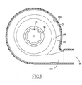
- the suction inlet 18 is defined in the half-shell 74 shown alone on the figure 5 .
- This inlet 18 is delimited by a convergent section 90 extending from the open end of the half-shell 74 to the suction mouth 30 of the wheel.
- the inner surface of the half-shell 74 comprises an axial counterbore 92 which is applied with a small clearance with respect to the cylindrical surface 62 of the wheel, thus ensuring the seal between the convergent section. input 90 and the volute 17 defined by the housing.
- the volute 17 is defined between the half-shells 72 and 74. It comprises, at the periphery of the wheel 14, facing the peripheral discharge passage 32, a circular channel 100 for guiding the gas flow.
- the peripheral channel 100 for guiding the gas flow is internally progressive in the plane of rotation of the wheel. It defines a spiral centered on the axis XX of the wheel.
- the channel 100 opens on the median space defined between the two half-shells and in which the impeller 14 extends.
- the channel 100 is connected to the discharge outlet by a straight duct 101 diverging delimited by the two half-shells 72, 74.
- This duct 101 extends in a direction tangential to the channel 100. Its diameter is gradually increasing from the channel 100 to the discharge outlet 20.
- the channel 100 is symmetrical in section relative to the output plane P of the wheel.
- This channel has at its base a region 102 substantially circular in section.
- This substantially circular region is centered along a point of the plane P of the wheel exit.
- the section of the substantially circular region 102 gradually increases toward the discharge outlet 20. It is increasing over most of the periphery of the housing.
- This region 102 substantially circular in section wraps around an outer contour 103 circular centered on the XX axis.
- the volute 17 externally has a circular contour and internally a spiral contour.
- the region 102 extends in section over an angular range greater than 180 °.
- the substantially circular region 102 provided at the base of the channel is extended by two parallel flat surfaces 104, 106 formed respectively on the inner faces of the half-shells 72 and 74. These surfaces extend parallel to the plane P output of the wheel.
- the outer edge of the wheel, in the thickness of which is formed the peripheral discharge passage 32 extends outside the substantially circular region 102 of the peripheral channel. Thus, the outer edge extends between the two annular flat surfaces 104 and 106.
- the peripheral channel 100 for guiding the gas flow defined at the periphery of the volute 17 has a substantially smooth surface and the space defined between this smooth surface and the peripheral discharge passage 32 of the wheel is free of any diffuser, this space being kept free for the flow of the gas stream.
- the impeller 14 is dimensioned, and in particular its blades 48 and 50, so that the compression ratio of the fan is between 1.05 and 1.12.
- the high speed of rotation of the wheel 14 and the symmetry of the peripheral channel 100 relative to the plane of exit of the gases from the wheel allow operation with very low noise emissions, while ensuring a satisfactory flow of the order of 2.5 l / s with a rise in pressure to 70 mbar.
- the sound pressure level at the suction is 64 dBA.
- the characteristics of the fan make it possible to obtain stable operation of the fan over the entire flow rate range.
- centrifugal fan is thus perfectly suitable for a respiratory assistance device.
- the fan is mounted in a frame.
- the output of the fan is connected to one end of a hose, the other end of the hose being adapted to receive a ventilation mask.
- a respiratory assistance device equipped with such a fan creates only low noise, thus improving the comfort of the user.
Abstract
Description
La présente invention concerne un ventilateur centrifuge à haute vitesse, du type comportant un carter définissant intérieurement une volute de guidage du flux gazeux, une roue à aubes d'entraînement du flux gazeux montée rotative dans la volute, et des moyens d'entraînement de la roue à aubes à une vitesse supérieure à 25.000 tours par minute, la roue à aubes présentant, autour de son axe, une bouche d'aspiration du flux gazeux s'étendant en regard d'une entrée d'aspiration ménagée dans le carter et, à sa périphérie, un passage de refoulement du flux gazeux de manière centrifuge suivant un plan de sortie de la roue, le carter présentant en outre une sortie de refoulement du flux gazeux en dehors de la volute.The present invention relates to a high-speed centrifugal fan, of the type comprising a casing internally defining a guiding volute of the gas flow, a gas turbine drive wheel wheel rotatably mounted in the volute, and means for driving the gas flow. impeller with a speed greater than 25,000 rpm, the impeller having, around its axis, a suction mouth of the gas flow extending opposite a suction inlet in the housing and, at its periphery, a discharge passage of the gas stream centrifugally along an exit plane of the wheel, the casing further having a discharge outlet of the gas flow outside the volute.
Pour les malades souffrant d'insuffisance respiratoire, il est connu des machines d'assistance respiratoire permettant d'insuffler aux malades de l'air ambiant au travers d'un masque maintenu en regard des voies respiratoires du patient.For patients suffering from respiratory insufficiency, respiratory assistance machines are known for infusing the patients with ambient air through a mask held facing the patient's respiratory tract.
Une telle machine d'assistance respiratoire comporte un ventilateur de mise en mouvement du flux d'air. Ce flux d'air est acheminé jusqu'au masque appliqué sur le visage du patient par des tuyauteries adaptées.Such a respiratory assistance machine comprises a fan for moving the airflow. This flow of air is conveyed to the mask applied to the patient's face by suitable pipes.
Les ventilateurs utilisés dans les machines d'assistance respiratoire sont des ventilateurs de petite taille ayant un coût de fabrication réduit. Ils fonctionnent généralement à une vitesse de rotation de l'ordre de 10.000 à 20.000 tours par minute.Fans used in respirator machines are small fans with a low manufacturing cost. They generally operate at a rotation speed of the order of 10,000 to 20,000 revolutions per minute.
On constate que les machines d'assistance respiratoire émettent, en fonctionnement, un bruit important qui occasionne des nuisances sonores pour le patient.It is found that the respiratory assistance machines emit, in operation, a significant noise that causes noise to the patient.
Le bruit émis provient essentiellement du ventilateur utilisé pour mettre l'air en mouvement.The noise emitted comes mainly from the fan used to put the air in motion.
Dans un domaine distinct de celui de l'invention,
L'invention a pour but de proposer un ventilateur de taille très réduite pouvant être implanté dans une machine d'assistance respiratoire et dont les émissions sonores sont réduites.The object of the invention is to propose a fan of very small size that can be implanted in a respiratory assistance machine and whose noise emissions are reduced.
A cet effet, l'invention a pour objet un ventilateur centrifuge à haute vitesse du type précité, caractérisé en ce que la volute définit, à sa périphérie, un canal de guidage du flux gazeux qui est essentiellement symétrique en section par rapport au plan de sortie de ladite roue.To this end, the subject of the invention is a high-speed centrifugal fan of the aforementioned type, characterized in that the volute defines, at its periphery, a channel for guiding the gas flow which is essentially symmetrical in section relative to the plane of output of said wheel.
Suivant des modes particuliers de réalisation, le ventilateur comporte l'une ou plusieurs des caractéristiques suivantes :
- la roue comporte, des aubes de part et d'autre desquelles sont ménagées des parois pleines annulaires, les parois pleines annulaires et les aubes définissant des conduits disjoints de guidage du flux gazeux ;
- chaque aube définit une surface gauche dont la normale varie suivant trois directions orthogonales le long de la longueur de l'aube ;
- le taux de compression est compris entre 1,05 et 1,12 ;
- la section du canal périphérique de guidage du flux gazeux défini à la périphérie de la volute est progressivement croissante en direction de la sortie de refoulement du flux gazeux en dehors de la volute ;
- le canal périphérique de guidage du flux gazeux défini à la périphérie de la volute décrit extérieurement un contour essentiellement circulaire dans le plan de sortie de la roue, lequel contour circulaire est centré sur l'axe de rotation de la roue ;
- le canal périphérique de guidage du flux gazeux défini à la périphérie de la volute comporte, à sa base, une région sensiblement circulaire en section, et symétrique par rapport au plan de sortie de la roue ;
- la région sensiblement circulaire en section s'étend sur une plage angulaire supérieure à 180° ;
- le bord périphérique de la roue s'étend en dehors de la région sensiblement circulaire en section définie à la base du canal périphérique de guidage du flux gazeux ; et
- l'espace entre le canal périphérique de guidage du flux gazeux et le passage périphérique de refoulement du flux gazeux est dépourvu de tout obstacle pour l'écoulement libre du flux gazeux.
- the wheel comprises, blades on either side of which are formed annular solid walls, the annular solid walls and the vanes defining disjoint conduits for guiding the gas flow;
- each blade defines a left surface whose normal varies along three orthogonal directions along the length of the blade;
- the compression ratio is between 1.05 and 1.12;
- the section of the peripheral channel for guiding the gaseous flow defined at the periphery of the volute is progressively increasing in the direction of the discharge outlet of the gaseous flow outside the volute;
- the peripheral channel for guiding the gas flow defined at the periphery of the volute externally describes a substantially circular contour in the exit plane of the wheel, which circular contour is centered on the axis of rotation of the wheel;
- the peripheral channel for guiding the gas flow defined at the periphery of the volute comprises, at its base, a substantially circular region in section, and symmetrical with respect to the exit plane of the wheel;
- the substantially circular region in section extends over an angular range greater than 180 °;
- the peripheral edge of the wheel extends outside the substantially circular region in section defined at the base of the peripheral channel for guiding the gas flow; and
- the space between the peripheral channel for guiding the gas flow and the peripheral discharge passage of the gas flow is free of any obstacle for the free flow of the gas flow.
L'invention a également pour objet un dispositif d'assistance respiratoire comportant un bâti dans lequel est monté un ventilateur centrifuge tel que défini ci-dessus et un flexible dont une extrémité est reliée en sortie dudit ventilateur et dont l'autre extrémité est adaptée pour recevoir un masque de ventilation.The invention also relates to a respiratory assistance device comprising a frame in which is mounted a centrifugal fan as defined above and a hose whose one end is connected at the output of said fan and whose other end is adapted to receive a ventilation mask.
L'invention sera mieux comprise à la lecture de la description qui va suivre, donnée uniquement à titre d'exemple et faite en se référant aux dessins, sur lesquels :
- la
figure 1 est une vue en coupe longitudinale du ventilateur centrifuge selon l'invention ; - la
figure 2 est une vue en bout du ventilateur selon l'invention ; - la
figure 3 est une vue en perspective de la roue à aubes du ventilateur desfigures 1 et2 ; - la
figure 4 est une vue en élévation de la roue à aubes de lafigure 3 dont le flasque a été retiré ; et - la
figure 5 est une vue en coupe du carter du ventilateur de lafigure 1 suivant son plan médian dans lequel tourne la roue à aubes.
- the
figure 1 is a longitudinal sectional view of the centrifugal fan according to the invention; - the
figure 2 is an end view of the fan according to the invention; - the
figure 3 is a perspective view of the fan impellerfigures 1 and2 ; - the
figure 4 is an elevational view of the paddle wheel of thefigure 3 whose flange has been removed; and - the
figure 5 is a sectional view of the fan housing of thefigure 1 following its median plane in which the paddle wheel rotates.
Le ventilateur représenté sur la
Le carter 16 présente en son centre, suivant l'axe de la roue à aubes 14, une entrée d'aspiration d'air 18. Il présente également à sa périphérie une sortie de refoulement d'air 20 s'étendant tangentiellement à la roue 14.The
Le moteur 12 est un moteur électrique de tout type adapté comportant un arbre de sortie 22 d'axe X-X. Le moteur est choisi pour que son arbre de sortie tourne à une vitesse supérieure à 25.000 tours par minute. Cette vitesse est de préférence comprise entre 47.000 et 56.000 tours par minute.The
La roue à aubes 14 est fixée directement sur l'arbre de sortie du moteur à l'aide d'une vis 24. Elle est généralement d'axe X-X et est montée rotative autour de cet axe. Ainsi la roue est entraînée à la même vitesse que le moteur 12.The
Comme illustré sur la
La roue à aubes 14 est formée d'un corps de roue 34 représenté seul sur la
Le corps de roue 34 et le flasque 36 sont assemblés par exemple par collage ou ultrasons.The
Le corps de roue 34 comporte un moyeu 38 traversé axialement par un alésage de réception de l'arbre 22. L'alésage présente à une extrémité un suralésage de réception d'une rondelle d'appui de la tête de vis 24 pour le montage de la roue sur l'arbre 22 du moteur.The
Le moyeu 38 est de révolution d'axe X-X. Il présente un diamètre progressivement croissant depuis son extrémité avant délimitant la bouche d'aspiration 30 jusqu'à son extrémité arrière présentant une forme générale de disque et délimitant le passage périphérique de refoulement 32. Ainsi, le moyeu 38 présente une surface latérale 44 de révolution dont le profil s'évase continûment de la bouche d'aspiration 30 au passage périphérique de refoulement 32. Cette surface latérale 44 définit la veine fluide. Elle est constituée par exemple par un tronçon d'hyperboloïde de révolution d'axe X-X.The
A son extrémité arrière délimitant le passage périphérique de refoulement 32, la surface 44 présente une plage annulaire plane 46 s'étendant parallèlement au plan P de sortie de la roue.At its rear end defining the
Comme illustré sur la
Les aubes primaires et secondaires sont de hauteur progressivement décroissante depuis la bouche d'aspiration 30 jusqu'au passage périphérique de refoulement 32, la hauteur étant mesurée suivant l'axe X-X.The primary and secondary blades are of progressively decreasing height from the
Les aubes principales 48 présentent un bord d'attaque 52 s'étendant radialement dans la bouche d'aspiration 30 de la roue. Au contraire, les aubes secondaires 50 ont un bord d'attaque 54 disposé en retrait de la bouche d'aspiration 30.The
Au-delà de leur bord d'attaque respectif, les profils des aubes 48 et 50 sont identiques jusqu'au passage périphérique de refoulement 32. Ces aubes définissent des surfaces gauches tri-dimensionnelles, c'est-à-dire que la normale à la surface de chaque aube varie continûment dans trois directions orthogonales suivant la longueur de chaque aube.Beyond their respective leading edge, the profiles of the
Le flasque 36 présente une forme extérieure et intérieure généralement tronconique: Sa surface intérieure, notée 56, est adaptée pour s'appliquer exactement sur la surface longitudinale libre des aubes primaires et secondaires. Ainsi, les aubes délimitent entre elles, entre la surface latérale 44 du moyeu et la surface intérieure 56 du flasque rapporté, des canaux indépendants de guidage du flux gazeux. Ces canaux ont une section progressivement croissante de la bouche d'aspiration 30 jusqu'au passage périphérique de refoulement 32.The
Le flasque 36 présente, en son centre, un tronçon cylindrique 58 définissant, avec l'extrémité avant du moyeu, la bouche d'aspiration 30. Les bords d'attaque 52 des aubes principales sont entourés par ce tronçon cylindrique 58.The
A son extrémité libre, la surface extérieure du tronçon cylindrique 58 présente une surface cylindrique 62 adaptée pour être disposée avec un jeu faible en regard d'un lamage correspondant ménagé dans le carter.At its free end, the outer surface of the
A sa périphérie extérieure, dans la région délimitant le passage périphérique de refoulement 32 de la roue, le flasque 36 présente une plage annulaire plane 64 s'étendant sensiblement parallèlement au plan de sortie P de la roue.At its outer periphery, in the region defining the
Ainsi, le passage périphérique de refoulement 32 est délimité par les deux plages annulaires 46 et 64 s'étendant presque parallèlement l'une à l'autre. La plage 46 est perpendiculaire à l'axe X-X, alors que la plage 64 est légèrement conique. Ces deux plages assurent le guidage du flux gazeux pour sa sortie de la roue suivant le plan P perpendiculaire à l'axe X-X de rotation.Thus, the
Le carter 16 comporte deux demi-coquilles 72, 74 reliées l'une à l'autre suivant un plan médian correspondant au plan P de sortie de la roue 14. Les deux demi-coquilles 72 et 74 sont réalisées en matière plastique injectée. Elles sont reliées l'une à l'autre par des agrafes métalliques 76 réparties suivant la périphérie du carter.The
La demi-coquille 72 est reliée à la partie fixe du moteur électrique 12 par une plaque 78 qui est vissée à la partie fixe du moteur et sur laquelle est boulonnée la demi-coquille 72.The half-
L'entrée d'aspiration 18 est définie dans la demi-coquille 74 représentée seule sur la
La volute 17 est définie, entre les demi-coquilles 72 et 74. Elle comporte, à la périphérie de la roue 14, en regard du passage périphérique de refoulement 32, un canal circulaire 100 de guidage du flux gazeux.The
Comme illustré sur la
Le canal 100 est relié à la sortie de refoulement par un conduit rectiligne 101 divergeant délimité par les deux demi-coquilles 72, 74. Ce conduit 101 s'étend suivant une direction tangentielle au canal 100. Son diamètre est progressivement croissant du canal 100 vers la sortie de refoulement 20.The
Selon l'invention, et comme illustré sur la
De part et d'autre, la région sensiblement circulaire 102 prévue à la base du canal est prolongée par deux surfaces planes parallèles 104, 106 ménagées respectivement sur les faces intérieures des demi-coquilles 72 et 74. Ces surfaces s'étendent parallèlement au plan P de sortie de la roue.On either side, the substantially
Le bord extérieur de la roue, dans l'épaisseur duquel est ménagé le passage périphérique de refoulement 32 s'étend en dehors de la région sensiblement circulaire 102 du canal périphérique. Ainsi, le bord extérieur s'étend entre les deux surfaces planes annulaires 104 et 106.The outer edge of the wheel, in the thickness of which is formed the
Le canal périphérique 100 de guidage du flux gazeux défini à la périphérie de la volute 17 présente une surface essentiellement lisse et l'espace délimité entre cette surface lisse et le passage périphérique de refoulement 32 de la roue est exempt de tout diffuseur, cet espace étant maintenu libre pour l'écoulement du flux gazeux.The
Avantageusement, la roue à aubes 14 est dimensionnée, et notamment ses aubes 48 et 50, de sorte que le taux de compression du ventilateur soit compris entre 1,05 et 1,12.Advantageously, the
Dans un tel ventilateur centrifuge, l'air est aspiré par l'entrée d'aspiration 18 et est rejeté par la sortie de refoulement 20.In such a centrifugal fan, the air is sucked by the
La vitesse élevée de rotation de la roue 14 et la symétrie du canal périphérique 100 par rapport au plan de sortie des gaz issus de la roue permettent un fonctionnement avec des émissions sonores très réduites, tout en permettant d'assurer un débit satisfaisant de l'ordre de 2,5 l/s avec une élévation de la pression à 70 mbars. Pour un tel débit, le niveau de pression sonore à l'aspiration est de 64 dBA.The high speed of rotation of the
De plus, les caractéristiques du ventilateur permettent d'obtenir un fonctionnement stable de celui-ci sur toute la plage de débits.In addition, the characteristics of the fan make it possible to obtain stable operation of the fan over the entire flow rate range.
Un tel ventilateur centrifuge convient ainsi parfaitement pour un dispositif d'assistance respiratoire.Such a centrifugal fan is thus perfectly suitable for a respiratory assistance device.
Dans un tel dispositif, le ventilateur est monté dans un bâti. La sortie du ventilateur est reliée à une extrémité d'un flexible, l'autre extrémité du flexible étant adaptée pour recevoir un masque de ventilation.In such a device, the fan is mounted in a frame. The output of the fan is connected to one end of a hose, the other end of the hose being adapted to receive a ventilation mask.
Un dispositif d'assistance respiratoire équipé d'un tel ventilateur ne crée que de faibles nuisances sonores, améliorant ainsi le confort de l'utilisateur.A respiratory assistance device equipped with such a fan creates only low noise, thus improving the comfort of the user.
Claims (10)
- A high speed centrifugal fan of the kind comprising a casing (16) defining in its interior a spiral (17) for guiding gas flow, a vaned wheel (14) for delivering the gas flow rotatably mounted in the spiral (17), and means (12) for driving the vaned wheel (14) at a speed greater than 25,000rpm, the vaned wheel having, about its axis (X-X), an inlet (30) for drawing in the gas flow extending opposite an aspiration inlet (18) arranged in the housing (16) and, at its periphery, a passage (32) for delivering the gas flow in a centrifugal manner along an outlet plane (P) of the wheel, the casing (16) having in addition an outlet (20) for delivering the gas flow from the spiral (17), characterised in that the spiral (17) defines, at its periphery, a passage (100) for guiding the gas flow which is substantially symmetrical in section in relation to the outlet plane (P) of the wheel.
- A fan according to claim 1, characterised in that the wheel comprises vanes (48,50) on both sides of which are arranged solid annular walls (36,38), the solid annular walls and the vanes defining separate passages for guiding the gas flow.
- A fan according to claim 1 or claim 2, characterised in that each vane (48,50) defines a twisted surface whose normal varies according to three orthogonal directions along the length of the vane.
- A fan according to any one of the preceding claims, characterised in that the compression ratio is between 1.05 and 1.12.
- A fan according to any one of the preceding claims, characterised in that the section of the peripheral passage (100) for guiding gas flow defined at the periphery of the spiral (17) increases progressively in the direction of the outlet (20) for delivery of the gas flow outside the spiral (17).
- A fan according to any one of the preceding claims, characterised in that the peripheral passage (100) for guiding gas flow defined at the periphery of the spiral (17) has an essentially circular external outline (103) in the outlet plane of the wheel (14), the circular outline (103) being centred on the axis (X-X) of rotation of the wheel.
- A fan according to any one of the preceding claims, characterised in that the peripheral passage (100) for guiding the gas flow defined at the periphery of the spiral comprises, at its base, a region (102) which is substantially circular in section and symmetrical in relation to the outlet plane (P) of the wheel.
- A fan according to claim 7, characterised in that the region (102) which is substantially circular in section extends for an angular range greater than 180°.
- A fan according to claim 6 or 7, characterised in that the peripheral edge of the wheel extends outside the region (102) which is substantially circular in section and defined at the base of the peripheral passage for guiding the gas flow.
- A fan according to any one of the preceding claims, characterised in that the space between the peripheral passage (100) for guiding the gas flow and the peripheral passage for delivering the gas flow (32) has no obstacles for the free flow of the gas flow.
Priority Applications (1)
| Application Number | Priority Date | Filing Date | Title |
|---|---|---|---|
| EP09175343A EP2151584B1 (en) | 2000-03-30 | 2001-03-28 | Centrifugal fan |
Applications Claiming Priority (2)
| Application Number | Priority Date | Filing Date | Title |
|---|---|---|---|
| FR0004068 | 2000-03-30 | ||
| FR0004068A FR2807117B1 (en) | 2000-03-30 | 2000-03-30 | CENTRIFUGAL FAN AND BREATHING ASSISTANCE DEVICE COMPRISING SAME |
Related Child Applications (1)
| Application Number | Title | Priority Date | Filing Date |
|---|---|---|---|
| EP09175343A Division EP2151584B1 (en) | 2000-03-30 | 2001-03-28 | Centrifugal fan |
Publications (2)
| Publication Number | Publication Date |
|---|---|
| EP1138954A1 EP1138954A1 (en) | 2001-10-04 |
| EP1138954B1 true EP1138954B1 (en) | 2009-12-16 |
Family
ID=8848683
Family Applications (2)
| Application Number | Title | Priority Date | Filing Date |
|---|---|---|---|
| EP01400803A Expired - Lifetime EP1138954B1 (en) | 2000-03-30 | 2001-03-28 | Centrifugal fan |
| EP09175343A Expired - Lifetime EP2151584B1 (en) | 2000-03-30 | 2001-03-28 | Centrifugal fan |
Family Applications After (1)
| Application Number | Title | Priority Date | Filing Date |
|---|---|---|---|
| EP09175343A Expired - Lifetime EP2151584B1 (en) | 2000-03-30 | 2001-03-28 | Centrifugal fan |
Country Status (5)
| Country | Link |
|---|---|
| EP (2) | EP1138954B1 (en) |
| AT (2) | ATE543004T1 (en) |
| DE (1) | DE60140777D1 (en) |
| ES (2) | ES2380108T3 (en) |
| FR (1) | FR2807117B1 (en) |
Cited By (52)
| Publication number | Priority date | Publication date | Assignee | Title |
|---|---|---|---|---|
| US7972111B2 (en) | 2009-03-04 | 2011-07-05 | Dyson Technology Limited | Fan assembly |
| US8052379B2 (en) | 2009-03-04 | 2011-11-08 | Dyson Technology Limited | Fan assembly |
| US8092166B2 (en) | 2008-12-11 | 2012-01-10 | Dyson Technology Limited | Fan |
| US8197226B2 (en) | 2009-03-04 | 2012-06-12 | Dyson Technology Limited | Fan assembly |
| US8246317B2 (en) | 2009-03-04 | 2012-08-21 | Dyson Technology Limited | Fan assembly |
| US8308445B2 (en) | 2007-09-04 | 2012-11-13 | Dyson Technology Limited | Fan |
| US8348629B2 (en) | 2008-09-23 | 2013-01-08 | Dyston Technology Limited | Fan |
| US8356804B2 (en) | 2009-03-04 | 2013-01-22 | Dyson Technology Limited | Humidifying apparatus |
| US8366403B2 (en) | 2010-08-06 | 2013-02-05 | Dyson Technology Limited | Fan assembly |
| US8403640B2 (en) | 2009-03-04 | 2013-03-26 | Dyson Technology Limited | Fan assembly |
| US8408869B2 (en) | 2009-03-04 | 2013-04-02 | Dyson Technology Limited | Fan assembly |
| US8430624B2 (en) | 2009-03-04 | 2013-04-30 | Dyson Technology Limited | Fan assembly |
| US8454322B2 (en) | 2009-11-06 | 2013-06-04 | Dyson Technology Limited | Fan having a magnetically attached remote control |
| US8469658B2 (en) | 2009-03-04 | 2013-06-25 | Dyson Technology Limited | Fan |
| US8469660B2 (en) | 2009-03-04 | 2013-06-25 | Dyson Technology Limited | Fan assembly |
| US8613601B2 (en) | 2009-03-04 | 2013-12-24 | Dyson Technology Limited | Fan assembly |
| US8721286B2 (en) | 2009-03-04 | 2014-05-13 | Dyson Technology Limited | Fan assembly |
| US8734094B2 (en) | 2010-08-06 | 2014-05-27 | Dyson Technology Limited | Fan assembly |
| US8770946B2 (en) | 2010-03-23 | 2014-07-08 | Dyson Technology Limited | Accessory for a fan |
| US8873940B2 (en) | 2010-08-06 | 2014-10-28 | Dyson Technology Limited | Fan assembly |
| US8882451B2 (en) | 2010-03-23 | 2014-11-11 | Dyson Technology Limited | Fan |
| US8894354B2 (en) | 2010-09-07 | 2014-11-25 | Dyson Technology Limited | Fan |
| US8967980B2 (en) | 2010-10-18 | 2015-03-03 | Dyson Technology Limited | Fan assembly |
| US8967979B2 (en) | 2010-10-18 | 2015-03-03 | Dyson Technology Limited | Fan assembly |
| US9011116B2 (en) | 2010-05-27 | 2015-04-21 | Dyson Technology Limited | Device for blowing air by means of a nozzle assembly |
| USD728092S1 (en) | 2013-08-01 | 2015-04-28 | Dyson Technology Limited | Fan |
| USD728770S1 (en) | 2013-08-01 | 2015-05-05 | Dyson Technology Limited | Fan |
| USD728769S1 (en) | 2013-08-01 | 2015-05-05 | Dyson Technology Limited | Fan |
| USD729372S1 (en) | 2013-03-07 | 2015-05-12 | Dyson Technology Limited | Fan |
| USD729374S1 (en) | 2013-03-07 | 2015-05-12 | Dyson Technology Limited | Fan |
| USD729375S1 (en) | 2013-03-07 | 2015-05-12 | Dyson Technology Limited | Fan |
| USD729373S1 (en) | 2013-03-07 | 2015-05-12 | Dyson Technology Limited | Fan |
| USD729376S1 (en) | 2013-03-07 | 2015-05-12 | Dyson Technology Limited | Fan |
| USD729925S1 (en) | 2013-03-07 | 2015-05-19 | Dyson Technology Limited | Fan |
| US9127855B2 (en) | 2011-07-27 | 2015-09-08 | Dyson Technology Limited | Fan assembly |
| US9127689B2 (en) | 2009-03-04 | 2015-09-08 | Dyson Technology Limited | Fan assembly |
| US9151299B2 (en) | 2012-02-06 | 2015-10-06 | Dyson Technology Limited | Fan |
| USD746425S1 (en) | 2013-01-18 | 2015-12-29 | Dyson Technology Limited | Humidifier |
| USD746966S1 (en) | 2013-01-18 | 2016-01-05 | Dyson Technology Limited | Humidifier |
| USD747450S1 (en) | 2013-01-18 | 2016-01-12 | Dyson Technology Limited | Humidifier |
| US9249809B2 (en) | 2012-02-06 | 2016-02-02 | Dyson Technology Limited | Fan |
| USD749231S1 (en) | 2013-01-18 | 2016-02-09 | Dyson Technology Limited | Humidifier |
| US9283573B2 (en) | 2012-02-06 | 2016-03-15 | Dyson Technology Limited | Fan assembly |
| US9328739B2 (en) | 2012-01-19 | 2016-05-03 | Dyson Technology Limited | Fan |
| US9366449B2 (en) | 2012-03-06 | 2016-06-14 | Dyson Technology Limited | Humidifying apparatus |
| US9410711B2 (en) | 2013-09-26 | 2016-08-09 | Dyson Technology Limited | Fan assembly |
| US9458853B2 (en) | 2011-07-27 | 2016-10-04 | Dyson Technology Limited | Fan assembly |
| US9513028B2 (en) | 2009-03-04 | 2016-12-06 | Dyson Technology Limited | Fan assembly |
| US9568006B2 (en) | 2012-05-16 | 2017-02-14 | Dyson Technology Limited | Fan |
| US9568021B2 (en) | 2012-05-16 | 2017-02-14 | Dyson Technology Limited | Fan |
| US9599356B2 (en) | 2014-07-29 | 2017-03-21 | Dyson Technology Limited | Humidifying apparatus |
| EP3181912A1 (en) | 2015-12-15 | 2017-06-21 | Peerfettibile FanService srl | Centrifugal fan |
Families Citing this family (27)
| Publication number | Priority date | Publication date | Assignee | Title |
|---|---|---|---|---|
| FR2843305B1 (en) | 2002-08-12 | 2004-10-22 | Airtechnologies Sa | CENTRIFUGAL VENTILATION DEVICE FOR ASSISTING A PATIENT IN ITS RESPIRATORY FUNCTION, COMPRISING A FLEXIBLE ELEMENT OF INTERPOSITION BETWEEN THE DYNAMIC AND FIXED ORGANS OF THE DEVICE |
| DE202004012015U1 (en) | 2004-07-31 | 2005-12-22 | Ebm-Papst Landshut Gmbh | radial impeller |
| US7452187B2 (en) * | 2005-08-09 | 2008-11-18 | Praxair Technology, Inc. | Compressor with large diameter shrouded three dimensional impeller |
| GB2464736A (en) | 2008-10-25 | 2010-04-28 | Dyson Technology Ltd | Fan with a filter |
| EP2627908B1 (en) | 2010-10-13 | 2019-03-20 | Dyson Technology Limited | A fan assembly |
| JP5778293B2 (en) | 2010-11-02 | 2015-09-16 | ダイソン テクノロジー リミテッド | Blower assembly |
| GB2486019B (en) | 2010-12-02 | 2013-02-20 | Dyson Technology Ltd | A fan |
| CN103410711B (en) * | 2011-08-15 | 2015-10-28 | 李耀强 | Without blade fan |
| GB201119500D0 (en) | 2011-11-11 | 2011-12-21 | Dyson Technology Ltd | A fan assembly |
| GB2496877B (en) | 2011-11-24 | 2014-05-07 | Dyson Technology Ltd | A fan assembly |
| GB2500011B (en) | 2012-03-06 | 2016-07-06 | Dyson Technology Ltd | A Humidifying Apparatus |
| GB2500017B (en) | 2012-03-06 | 2015-07-29 | Dyson Technology Ltd | A Humidifying Apparatus |
| EP2823183A1 (en) | 2012-03-06 | 2015-01-14 | Dyson Technology Limited | A fan assembly |
| GB2512192B (en) | 2012-03-06 | 2015-08-05 | Dyson Technology Ltd | A Humidifying Apparatus |
| GB2500012B (en) | 2012-03-06 | 2016-07-06 | Dyson Technology Ltd | A Humidifying Apparatus |
| GB2500903B (en) | 2012-04-04 | 2015-06-24 | Dyson Technology Ltd | Heating apparatus |
| GB2501301B (en) | 2012-04-19 | 2016-02-03 | Dyson Technology Ltd | A fan assembly |
| RU2636974C2 (en) | 2012-05-16 | 2017-11-29 | Дайсон Текнолоджи Лимитед | Fan |
| GB2503907B (en) | 2012-07-11 | 2014-05-28 | Dyson Technology Ltd | A fan assembly |
| GB2510195B (en) | 2013-01-29 | 2016-04-27 | Dyson Technology Ltd | A fan assembly |
| CA2899747A1 (en) | 2013-01-29 | 2014-08-07 | Dyson Technology Limited | A fan assembly |
| GB2530906B (en) | 2013-07-09 | 2017-05-10 | Dyson Technology Ltd | A fan assembly |
| GB2528704A (en) | 2014-07-29 | 2016-02-03 | Dyson Technology Ltd | Humidifying apparatus |
| GB2528708B (en) | 2014-07-29 | 2016-06-29 | Dyson Technology Ltd | A fan assembly |
| FR3036143B1 (en) * | 2015-05-12 | 2019-07-05 | Air Liquide Medical Systems | IMPROVED MOTOR-MOTOR SEALANT MICRO-BLOWER FOR RESPIRATORY ASSISTANCE APPARATUS |
| CN113339299B (en) * | 2021-06-17 | 2022-12-23 | 浙江理工大学 | High-speed miniature three-dimensional flow turbofan applicable to breathing machine |
| CN114857051A (en) * | 2022-05-23 | 2022-08-05 | 蔡义祥 | Novel ventilation equipment and fan |
Family Cites Families (8)
| Publication number | Priority date | Publication date | Assignee | Title |
|---|---|---|---|---|
| US2796836A (en) * | 1947-12-30 | 1957-06-25 | Buchi Alfred | Rotors for compressing machines such as centrifugal blowers and pumps |
| US2830755A (en) * | 1955-05-23 | 1958-04-15 | Borg Warner | Rotary compressor |
| GB1407408A (en) * | 1971-10-21 | 1975-09-24 | British Gas Corp | Air supply for breathing apparatus |
| FI902308A (en) * | 1990-05-08 | 1991-11-09 | High Speed Tech Ltd Oy | KOMPRESSOR. |
| DE4037229A1 (en) * | 1990-11-23 | 1992-05-27 | Philips Patentverwaltung | BLOWER UNIT FOR GENERATING GAS FLOWS |
| US5363674A (en) * | 1993-05-04 | 1994-11-15 | Ecoair Corp. | Zero superheat refrigeration compression system |
| US5639217A (en) * | 1996-02-12 | 1997-06-17 | Kawasaki Jukogyo Kabushiki Kaisha | Splitter-type impeller |
| US5924847A (en) * | 1997-08-11 | 1999-07-20 | Mainstream Engineering Corp. | Magnetic bearing centrifugal refrigeration compressor and refrigerant having minimum specific enthalpy rise |
-
2000
- 2000-03-30 FR FR0004068A patent/FR2807117B1/en not_active Expired - Fee Related
-
2001
- 2001-03-28 EP EP01400803A patent/EP1138954B1/en not_active Expired - Lifetime
- 2001-03-28 AT AT09175343T patent/ATE543004T1/en active
- 2001-03-28 ES ES09175343T patent/ES2380108T3/en not_active Expired - Lifetime
- 2001-03-28 DE DE60140777T patent/DE60140777D1/en not_active Expired - Fee Related
- 2001-03-28 ES ES01400803T patent/ES2338095T3/en not_active Expired - Lifetime
- 2001-03-28 EP EP09175343A patent/EP2151584B1/en not_active Expired - Lifetime
- 2001-03-28 AT AT01400803T patent/ATE452294T1/en active
Cited By (72)
| Publication number | Priority date | Publication date | Assignee | Title |
|---|---|---|---|---|
| US8308445B2 (en) | 2007-09-04 | 2012-11-13 | Dyson Technology Limited | Fan |
| US9249810B2 (en) | 2007-09-04 | 2016-02-02 | Dyson Technology Limited | Fan |
| US8764412B2 (en) | 2007-09-04 | 2014-07-01 | Dyson Technology Limited | Fan |
| US8403650B2 (en) | 2007-09-04 | 2013-03-26 | Dyson Technology Limited | Fan |
| US8348629B2 (en) | 2008-09-23 | 2013-01-08 | Dyston Technology Limited | Fan |
| US8092166B2 (en) | 2008-12-11 | 2012-01-10 | Dyson Technology Limited | Fan |
| US8529203B2 (en) | 2009-03-04 | 2013-09-10 | Dyson Technology Limited | Fan assembly |
| US8708650B2 (en) | 2009-03-04 | 2014-04-29 | Dyson Technology Limited | Fan assembly |
| US8308432B2 (en) | 2009-03-04 | 2012-11-13 | Dyson Technology Limited | Fan assembly |
| US8348596B2 (en) | 2009-03-04 | 2013-01-08 | Dyson Technology Limited | Fan assembly |
| US8356804B2 (en) | 2009-03-04 | 2013-01-22 | Dyson Technology Limited | Humidifying apparatus |
| US8052379B2 (en) | 2009-03-04 | 2011-11-08 | Dyson Technology Limited | Fan assembly |
| US8246317B2 (en) | 2009-03-04 | 2012-08-21 | Dyson Technology Limited | Fan assembly |
| US8403640B2 (en) | 2009-03-04 | 2013-03-26 | Dyson Technology Limited | Fan assembly |
| US8408869B2 (en) | 2009-03-04 | 2013-04-02 | Dyson Technology Limited | Fan assembly |
| US8430624B2 (en) | 2009-03-04 | 2013-04-30 | Dyson Technology Limited | Fan assembly |
| US9513028B2 (en) | 2009-03-04 | 2016-12-06 | Dyson Technology Limited | Fan assembly |
| US8469658B2 (en) | 2009-03-04 | 2013-06-25 | Dyson Technology Limited | Fan |
| US8469660B2 (en) | 2009-03-04 | 2013-06-25 | Dyson Technology Limited | Fan assembly |
| US8469655B2 (en) | 2009-03-04 | 2013-06-25 | Dyson Technology Limited | Fan assembly |
| US9127689B2 (en) | 2009-03-04 | 2015-09-08 | Dyson Technology Limited | Fan assembly |
| US8613601B2 (en) | 2009-03-04 | 2013-12-24 | Dyson Technology Limited | Fan assembly |
| US8684687B2 (en) | 2009-03-04 | 2014-04-01 | Dyson Technology Limited | Fan assembly |
| US8348597B2 (en) | 2009-03-04 | 2013-01-08 | Dyson Technology Limited | Fan assembly |
| US8714937B2 (en) | 2009-03-04 | 2014-05-06 | Dyson Technology Limited | Fan assembly |
| US8721286B2 (en) | 2009-03-04 | 2014-05-13 | Dyson Technology Limited | Fan assembly |
| US9599368B2 (en) | 2009-03-04 | 2017-03-21 | Dyson Technology Limited | Nozzle for bladeless fan assembly with heater |
| US8197226B2 (en) | 2009-03-04 | 2012-06-12 | Dyson Technology Limited | Fan assembly |
| US7972111B2 (en) | 2009-03-04 | 2011-07-05 | Dyson Technology Limited | Fan assembly |
| US8783663B2 (en) | 2009-03-04 | 2014-07-22 | Dyson Technology Limited | Humidifying apparatus |
| US8784049B2 (en) | 2009-03-04 | 2014-07-22 | Dyson Technology Limited | Fan |
| US8784071B2 (en) | 2009-03-04 | 2014-07-22 | Dyson Technology Limited | Fan assembly |
| US8932028B2 (en) | 2009-03-04 | 2015-01-13 | Dyson Technology Limited | Fan assembly |
| US9004878B2 (en) | 2009-11-06 | 2015-04-14 | Dyson Technology Limited | Fan having a magnetically attached remote control |
| US8454322B2 (en) | 2009-11-06 | 2013-06-04 | Dyson Technology Limited | Fan having a magnetically attached remote control |
| US8882451B2 (en) | 2010-03-23 | 2014-11-11 | Dyson Technology Limited | Fan |
| US8770946B2 (en) | 2010-03-23 | 2014-07-08 | Dyson Technology Limited | Accessory for a fan |
| US9011116B2 (en) | 2010-05-27 | 2015-04-21 | Dyson Technology Limited | Device for blowing air by means of a nozzle assembly |
| US8873940B2 (en) | 2010-08-06 | 2014-10-28 | Dyson Technology Limited | Fan assembly |
| US8734094B2 (en) | 2010-08-06 | 2014-05-27 | Dyson Technology Limited | Fan assembly |
| US8366403B2 (en) | 2010-08-06 | 2013-02-05 | Dyson Technology Limited | Fan assembly |
| US8894354B2 (en) | 2010-09-07 | 2014-11-25 | Dyson Technology Limited | Fan |
| US8967980B2 (en) | 2010-10-18 | 2015-03-03 | Dyson Technology Limited | Fan assembly |
| US8967979B2 (en) | 2010-10-18 | 2015-03-03 | Dyson Technology Limited | Fan assembly |
| US9458853B2 (en) | 2011-07-27 | 2016-10-04 | Dyson Technology Limited | Fan assembly |
| US9127855B2 (en) | 2011-07-27 | 2015-09-08 | Dyson Technology Limited | Fan assembly |
| US9335064B2 (en) | 2011-07-27 | 2016-05-10 | Dyson Technology Limited | Fan assembly |
| US9291361B2 (en) | 2011-07-27 | 2016-03-22 | Dyson Technology Limited | Fan assembly |
| US9328739B2 (en) | 2012-01-19 | 2016-05-03 | Dyson Technology Limited | Fan |
| US9249809B2 (en) | 2012-02-06 | 2016-02-02 | Dyson Technology Limited | Fan |
| US9151299B2 (en) | 2012-02-06 | 2015-10-06 | Dyson Technology Limited | Fan |
| US9283573B2 (en) | 2012-02-06 | 2016-03-15 | Dyson Technology Limited | Fan assembly |
| US9366449B2 (en) | 2012-03-06 | 2016-06-14 | Dyson Technology Limited | Humidifying apparatus |
| US9568021B2 (en) | 2012-05-16 | 2017-02-14 | Dyson Technology Limited | Fan |
| US9568006B2 (en) | 2012-05-16 | 2017-02-14 | Dyson Technology Limited | Fan |
| USD749231S1 (en) | 2013-01-18 | 2016-02-09 | Dyson Technology Limited | Humidifier |
| USD746966S1 (en) | 2013-01-18 | 2016-01-05 | Dyson Technology Limited | Humidifier |
| USD746425S1 (en) | 2013-01-18 | 2015-12-29 | Dyson Technology Limited | Humidifier |
| USD747450S1 (en) | 2013-01-18 | 2016-01-12 | Dyson Technology Limited | Humidifier |
| USD729376S1 (en) | 2013-03-07 | 2015-05-12 | Dyson Technology Limited | Fan |
| USD729372S1 (en) | 2013-03-07 | 2015-05-12 | Dyson Technology Limited | Fan |
| USD729925S1 (en) | 2013-03-07 | 2015-05-19 | Dyson Technology Limited | Fan |
| USD729373S1 (en) | 2013-03-07 | 2015-05-12 | Dyson Technology Limited | Fan |
| USD729375S1 (en) | 2013-03-07 | 2015-05-12 | Dyson Technology Limited | Fan |
| USD729374S1 (en) | 2013-03-07 | 2015-05-12 | Dyson Technology Limited | Fan |
| USD728769S1 (en) | 2013-08-01 | 2015-05-05 | Dyson Technology Limited | Fan |
| USD728770S1 (en) | 2013-08-01 | 2015-05-05 | Dyson Technology Limited | Fan |
| USD728092S1 (en) | 2013-08-01 | 2015-04-28 | Dyson Technology Limited | Fan |
| US9410711B2 (en) | 2013-09-26 | 2016-08-09 | Dyson Technology Limited | Fan assembly |
| US9599356B2 (en) | 2014-07-29 | 2017-03-21 | Dyson Technology Limited | Humidifying apparatus |
| EP3181912A1 (en) | 2015-12-15 | 2017-06-21 | Peerfettibile FanService srl | Centrifugal fan |
| EP3181912B1 (en) * | 2015-12-15 | 2019-09-04 | Aeromeccanica Stranich SpA | Centrifugal fan |
Also Published As
| Publication number | Publication date |
|---|---|
| DE60140777D1 (en) | 2010-01-28 |
| ES2338095T3 (en) | 2010-05-04 |
| FR2807117B1 (en) | 2002-12-13 |
| EP2151584A1 (en) | 2010-02-10 |
| ES2380108T3 (en) | 2012-05-08 |
| ATE543004T1 (en) | 2012-02-15 |
| ATE452294T1 (en) | 2010-01-15 |
| EP1138954A1 (en) | 2001-10-04 |
| FR2807117A1 (en) | 2001-10-05 |
| EP2151584B1 (en) | 2012-01-25 |
Similar Documents
| Publication | Publication Date | Title |
|---|---|---|
| EP1138954B1 (en) | Centrifugal fan | |
| US8845268B2 (en) | Multistage compressor with improved map width performance | |
| FR2908482A1 (en) | Gas i.e. air, delivering apparatus i.e. breathing assistance apparatus, has case, motor and volute delimiting gas flow pipe that extends towards volute opening, where case interiorly forms plot that projects near wheel hub after assembling | |
| FR2745604A1 (en) | FUEL TURBOCHARGER | |
| FR2726324A1 (en) | HELICOID FAN FOR THE RADIATOR OF AN INTERNAL COMBUSTION ENGINE | |
| JP2018526574A (en) | Turbo fan with cooling body | |
| US7008189B2 (en) | Centrifugal fan | |
| WO2019092358A1 (en) | Method for moving air | |
| EP3719283B1 (en) | Pinion for driving an air/oil separator of an accessories unit of a turbine engine | |
| EP0541429B1 (en) | Profiled shroud for a fan rotor and its use in motor driven fans for cars | |
| EP3011185B1 (en) | Centrifugal rotor | |
| CA2762308A1 (en) | Centrifugal impeller for a compressor | |
| EP0242248B1 (en) | Radial ventilator, especially for motor vehicle air conditioning | |
| CH704632B1 (en) | Inductor rotating hub and converge to suction floor of a pump. | |
| FR2910081A1 (en) | Gas delivery apparatus i.e. respiratory assistance apparatus, has wall extended around motor at constant distance from motor such that case and motor delimit gas flow passage, and impeller rotated to generate forced gas stream in passage | |
| FR3087855A1 (en) | A CENTRIFUGAL TURBOCHARGER HAVING A GAS FLOW PATH HAVING A RELAXATION CHAMBER | |
| JP6088134B2 (en) | Supersonic compressor rotor and its assembly method | |
| WO2017168642A1 (en) | Impeller, rotary machine, and turbocharger | |
| EP1348871A1 (en) | Low flow centrifugal pump with increased suction height | |
| JP3794543B2 (en) | Centrifugal compressor | |
| EP4034755A1 (en) | Device for cooling a turbine casing with air jets | |
| FR2878914A1 (en) | Air compressor for supercharged internal combustion engine, has butterfly valve moved between full open and close positions, and annular chamber, disposed around suction pipeline, to spin fresh air before its introduction in pipeline | |
| FR2781531A1 (en) | Centrifugal fan for vehicle air conditioning systems has outlet from voluted case connected to outlet flow pipe via an intermediate flaring section, which gives abrupt increase in cross sectional area of flow. | |
| FR2781844A1 (en) | Motorized ventilator group for air conditioning in motor vehicle has centrifugal turbine driven by motor in involute casing | |
| WO2018200612A1 (en) | Forced induction device having inlet with rotationally asymmetric groove |
Legal Events
| Date | Code | Title | Description |
|---|---|---|---|
| PUAI | Public reference made under article 153(3) epc to a published international application that has entered the european phase |
Free format text: ORIGINAL CODE: 0009012 |
|
| AK | Designated contracting states |
Kind code of ref document: A1 Designated state(s): AT BE CH CY DE DK ES FI FR GB GR IE IT LI LU MC NL PT SE TR |
|
| AX | Request for extension of the european patent |
Free format text: AL;LT;LV;MK;RO;SI |
|
| 17P | Request for examination filed |
Effective date: 20020318 |
|
| AKX | Designation fees paid |
Free format text: AT BE CH CY DE DK ES FI FR GB GR IE IT LI LU MC NL PT SE TR |
|
| 17Q | First examination report despatched |
Effective date: 20070326 |
|
| GRAP | Despatch of communication of intention to grant a patent |
Free format text: ORIGINAL CODE: EPIDOSNIGR1 |
|
| GRAS | Grant fee paid |
Free format text: ORIGINAL CODE: EPIDOSNIGR3 |
|
| GRAA | (expected) grant |
Free format text: ORIGINAL CODE: 0009210 |
|
| AK | Designated contracting states |
Kind code of ref document: B1 Designated state(s): AT BE CH CY DE DK ES FI FR GB GR IE IT LI LU MC NL PT SE TR |
|
| REG | Reference to a national code |
Ref country code: GB Ref legal event code: FG4D Free format text: NOT ENGLISH |
|
| REG | Reference to a national code |
Ref country code: CH Ref legal event code: EP |
|
| REG | Reference to a national code |
Ref country code: IE Ref legal event code: FG4D |
|
| REF | Corresponds to: |
Ref document number: 60140777 Country of ref document: DE Date of ref document: 20100128 Kind code of ref document: P |
|
| REG | Reference to a national code |
Ref country code: NL Ref legal event code: T3 |
|
| PG25 | Lapsed in a contracting state [announced via postgrant information from national office to epo] |
Ref country code: FI Free format text: LAPSE BECAUSE OF FAILURE TO SUBMIT A TRANSLATION OF THE DESCRIPTION OR TO PAY THE FEE WITHIN THE PRESCRIBED TIME-LIMIT Effective date: 20091216 Ref country code: SE Free format text: LAPSE BECAUSE OF FAILURE TO SUBMIT A TRANSLATION OF THE DESCRIPTION OR TO PAY THE FEE WITHIN THE PRESCRIBED TIME-LIMIT Effective date: 20091216 |
|
| REG | Reference to a national code |
Ref country code: ES Ref legal event code: FG2A Ref document number: 2338095 Country of ref document: ES Kind code of ref document: T3 |
|
| REG | Reference to a national code |
Ref country code: IE Ref legal event code: FD4D |
|
| PG25 | Lapsed in a contracting state [announced via postgrant information from national office to epo] |
Ref country code: PT Free format text: LAPSE BECAUSE OF FAILURE TO SUBMIT A TRANSLATION OF THE DESCRIPTION OR TO PAY THE FEE WITHIN THE PRESCRIBED TIME-LIMIT Effective date: 20100416 Ref country code: IE Free format text: LAPSE BECAUSE OF FAILURE TO SUBMIT A TRANSLATION OF THE DESCRIPTION OR TO PAY THE FEE WITHIN THE PRESCRIBED TIME-LIMIT Effective date: 20091216 |
|
| PLBI | Opposition filed |
Free format text: ORIGINAL CODE: 0009260 |
|
| BERE | Be: lapsed |
Owner name: TECHNOFAN Effective date: 20100331 |
|
| REG | Reference to a national code |
Ref country code: NL Ref legal event code: V1 Effective date: 20101001 |
|
| PLAX | Notice of opposition and request to file observation + time limit sent |
Free format text: ORIGINAL CODE: EPIDOSNOBS2 |
|
| 26 | Opposition filed |
Opponent name: SIEMENS AG CT IP O Effective date: 20100916 |
|
| PG25 | Lapsed in a contracting state [announced via postgrant information from national office to epo] |
Ref country code: MC Free format text: LAPSE BECAUSE OF NON-PAYMENT OF DUE FEES Effective date: 20100331 Ref country code: CY Free format text: LAPSE BECAUSE OF FAILURE TO SUBMIT A TRANSLATION OF THE DESCRIPTION OR TO PAY THE FEE WITHIN THE PRESCRIBED TIME-LIMIT Effective date: 20091216 Ref country code: GR Free format text: LAPSE BECAUSE OF FAILURE TO SUBMIT A TRANSLATION OF THE DESCRIPTION OR TO PAY THE FEE WITHIN THE PRESCRIBED TIME-LIMIT Effective date: 20100317 |
|
| REG | Reference to a national code |
Ref country code: CH Ref legal event code: PL |
|
| GBPC | Gb: european patent ceased through non-payment of renewal fee |
Effective date: 20100328 |
|
| PG25 | Lapsed in a contracting state [announced via postgrant information from national office to epo] |
Ref country code: NL Free format text: LAPSE BECAUSE OF NON-PAYMENT OF DUE FEES Effective date: 20101001 Ref country code: DK Free format text: LAPSE BECAUSE OF FAILURE TO SUBMIT A TRANSLATION OF THE DESCRIPTION OR TO PAY THE FEE WITHIN THE PRESCRIBED TIME-LIMIT Effective date: 20091216 |
|
| PLAF | Information modified related to communication of a notice of opposition and request to file observations + time limit |
Free format text: ORIGINAL CODE: EPIDOSCOBS2 |
|
| PG25 | Lapsed in a contracting state [announced via postgrant information from national office to epo] |
Ref country code: BE Free format text: LAPSE BECAUSE OF NON-PAYMENT OF DUE FEES Effective date: 20100331 Ref country code: CH Free format text: LAPSE BECAUSE OF NON-PAYMENT OF DUE FEES Effective date: 20100331 Ref country code: DE Free format text: LAPSE BECAUSE OF NON-PAYMENT OF DUE FEES Effective date: 20101001 Ref country code: LI Free format text: LAPSE BECAUSE OF NON-PAYMENT OF DUE FEES Effective date: 20100331 |
|
| REG | Reference to a national code |
Ref country code: DE Ref legal event code: R073 Ref document number: 60140777 Country of ref document: DE |
|
| PG25 | Lapsed in a contracting state [announced via postgrant information from national office to epo] |
Ref country code: GB Free format text: LAPSE BECAUSE OF NON-PAYMENT OF DUE FEES Effective date: 20100328 |
|
| REG | Reference to a national code |
Ref country code: GB Ref legal event code: S28 Free format text: APPLICATION FILED |
|
| PLBB | Reply of patent proprietor to notice(s) of opposition received |
Free format text: ORIGINAL CODE: EPIDOSNOBS3 |
|
| PGRI | Patent reinstated in contracting state [announced from national office to epo] |
Ref country code: IT Effective date: 20110501 |
|
| REG | Reference to a national code |
Ref country code: DE Ref legal event code: R081 Ref document number: 60140777 Country of ref document: DE Owner name: COVIDIEN AG, CH Free format text: FORMER OWNER: TECHNOFAN, BLAGNAC, FR Effective date: 20110314 |
|
| RAP2 | Party data changed (patent owner data changed or rights of a patent transferred) |
Owner name: COVIDIEN AG |
|
| REG | Reference to a national code |
Ref country code: GB Ref legal event code: 732E Free format text: REGISTERED BETWEEN 20111103 AND 20111109 |
|
| REG | Reference to a national code |
Ref country code: GB Ref legal event code: S28 Free format text: RESTORATION ALLOWED Effective date: 20111213 |
|
| PG25 | Lapsed in a contracting state [announced via postgrant information from national office to epo] |
Ref country code: LU Free format text: LAPSE BECAUSE OF NON-PAYMENT OF DUE FEES Effective date: 20100328 |
|
| PG25 | Lapsed in a contracting state [announced via postgrant information from national office to epo] |
Ref country code: TR Free format text: LAPSE BECAUSE OF FAILURE TO SUBMIT A TRANSLATION OF THE DESCRIPTION OR TO PAY THE FEE WITHIN THE PRESCRIBED TIME-LIMIT Effective date: 20091216 |
|
| REG | Reference to a national code |
Ref country code: DE Ref legal event code: R102 Ref document number: 60140777 Country of ref document: DE Effective date: 20131127 |
|
| REG | Reference to a national code |
Ref country code: DE Ref legal event code: R011 Ref document number: 60140777 Country of ref document: DE Ref country code: DE Ref legal event code: R124 Ref document number: 60140777 Country of ref document: DE |
|
| REG | Reference to a national code |
Ref country code: FR Ref legal event code: PLFP Year of fee payment: 15 |
|
| REG | Reference to a national code |
Ref country code: DE Ref legal event code: R100 Ref document number: 60140777 Country of ref document: DE |
|
| PLCK | Communication despatched that opposition was rejected |
Free format text: ORIGINAL CODE: EPIDOSNREJ1 |
|
| PLBN | Opposition rejected |
Free format text: ORIGINAL CODE: 0009273 |
|
| STAA | Information on the status of an ep patent application or granted ep patent |
Free format text: STATUS: OPPOSITION REJECTED |
|
| 27O | Opposition rejected |
Effective date: 20150701 |
|
| REG | Reference to a national code |
Ref country code: FR Ref legal event code: PLFP Year of fee payment: 16 |
|
| PGFP | Annual fee paid to national office [announced via postgrant information from national office to epo] |
Ref country code: IT Payment date: 20160224 Year of fee payment: 16 Ref country code: ES Payment date: 20160304 Year of fee payment: 16 |
|
| PGFP | Annual fee paid to national office [announced via postgrant information from national office to epo] |
Ref country code: FR Payment date: 20160219 Year of fee payment: 16 Ref country code: AT Payment date: 20160219 Year of fee payment: 16 Ref country code: GB Payment date: 20160223 Year of fee payment: 16 |
|
| REG | Reference to a national code |
Ref country code: AT Ref legal event code: MM01 Ref document number: 452294 Country of ref document: AT Kind code of ref document: T Effective date: 20170328 |
|
| GBPC | Gb: european patent ceased through non-payment of renewal fee |
Effective date: 20170328 |
|
| REG | Reference to a national code |
Ref country code: FR Ref legal event code: ST Effective date: 20171130 |
|
| PG25 | Lapsed in a contracting state [announced via postgrant information from national office to epo] |
Ref country code: AT Free format text: LAPSE BECAUSE OF NON-PAYMENT OF DUE FEES Effective date: 20170328 Ref country code: FR Free format text: LAPSE BECAUSE OF NON-PAYMENT OF DUE FEES Effective date: 20170331 |
|
| PG25 | Lapsed in a contracting state [announced via postgrant information from national office to epo] |
Ref country code: GB Free format text: LAPSE BECAUSE OF NON-PAYMENT OF DUE FEES Effective date: 20170328 Ref country code: IT Free format text: LAPSE BECAUSE OF NON-PAYMENT OF DUE FEES Effective date: 20170328 |
|
| REG | Reference to a national code |
Ref country code: ES Ref legal event code: FD2A Effective date: 20180704 |
|
| PG25 | Lapsed in a contracting state [announced via postgrant information from national office to epo] |
Ref country code: ES Free format text: LAPSE BECAUSE OF NON-PAYMENT OF DUE FEES Effective date: 20170329 |