EP1138916A2 - Verfahren zur Korrektur der Ansteuerspannung eines elektrisch betriebenen Aktors eines Einspritzventils für einen Verbrennungsmotor - Google Patents
Verfahren zur Korrektur der Ansteuerspannung eines elektrisch betriebenen Aktors eines Einspritzventils für einen Verbrennungsmotor Download PDFInfo
- Publication number
- EP1138916A2 EP1138916A2 EP01104673A EP01104673A EP1138916A2 EP 1138916 A2 EP1138916 A2 EP 1138916A2 EP 01104673 A EP01104673 A EP 01104673A EP 01104673 A EP01104673 A EP 01104673A EP 1138916 A2 EP1138916 A2 EP 1138916A2
- Authority
- EP
- European Patent Office
- Prior art keywords
- offset values
- control voltage
- offset
- values
- injection valve
- Prior art date
- Legal status (The legal status is an assumption and is not a legal conclusion. Google has not performed a legal analysis and makes no representation as to the accuracy of the status listed.)
- Granted
Links
Images
Classifications
-
- F—MECHANICAL ENGINEERING; LIGHTING; HEATING; WEAPONS; BLASTING
- F02—COMBUSTION ENGINES; HOT-GAS OR COMBUSTION-PRODUCT ENGINE PLANTS
- F02D—CONTROLLING COMBUSTION ENGINES
- F02D41/00—Electrical control of supply of combustible mixture or its constituents
- F02D41/20—Output circuits, e.g. for controlling currents in command coils
-
- F—MECHANICAL ENGINEERING; LIGHTING; HEATING; WEAPONS; BLASTING
- F02—COMBUSTION ENGINES; HOT-GAS OR COMBUSTION-PRODUCT ENGINE PLANTS
- F02D—CONTROLLING COMBUSTION ENGINES
- F02D41/00—Electrical control of supply of combustible mixture or its constituents
- F02D41/30—Controlling fuel injection
- F02D41/38—Controlling fuel injection of the high pressure type
- F02D41/3809—Common rail control systems
Definitions
- the invention is based on a method for correcting the Control voltage of an electrically operated actuator Injector for an internal combustion engine according to the Genus of the main claim. It is already known at Common rail injection systems to use injectors which a piezoelectric actuator for indirect actuation use a nozzle needle. The actuator comes with a Control voltage activated and actuated with the help of its Change in length of the injector nozzle needle. The The control voltage must match the current one Pressure ratios in the common rail system can be adjusted because otherwise no or no satisfactory injection of the fuel takes place. Furthermore, it is required the drive voltage at high speed to adapt to the given conditions and if possible to change injection synchronously.
- the inventive method for correcting the Control voltage of an electrically operated actuator Injector for an internal combustion engine with the characteristic features of the main claim has the compared to the advantage that an injection-synchronous correction the control voltage occurs through certain offset values. It is particularly advantageous that the voltage correction is based on is based on a universal functional structure and not knowledge of the dependence on individuals Operating parameters such as rail pressure, temperature or the like needs and essentially in sync with Fuel injection runs. This is the procedure universally applicable and requires in an advantageous manner no complex adjustments to individual engine types or Injection systems.
- This Adaptation factor takes into account the individual operating and Environmental parameters and can easily be for one certain system type, for example, found empirically become.
- the Adjustment factor is an optimal correction of the Control voltage possible.
- the selected offset values become advantageous synchronized with the control voltage to the control circuit transferred so that the desired drive voltage for Control of the actuator is available directly.
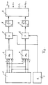
- FIG. 1 An embodiment of the invention is in the drawing shown and in the following description explained.
- the figure shows a block diagram of a Control circuit.
- the figure shows a basic block diagram, according to which the offset values for the control voltage U a are formed.
- n values for the offset voltage from the past are stored, n being an arbitrarily selected positive integer.
- the stored offset values thus contain the respective maximum Mx and minimum Mn with which the previous control voltages U a were formed.
- Y offset values are now fed to the comparators 2 and 4, the comparator 2 looking for the maximum Mx and the comparator 4 for the minimum Mn.
- Y is a predetermined number for the offset values to be checked.
- the maximum offset value is then available at the output of the comparator 2 and the minimum offset value is available for further processing at the output of the comparator 4.
- a correction element 3 is provided with which a factor k that can be applied depending on the vehicle or engine type can be determined.
- the output of the correction element 3 is fed to an input of a multiplier 5 or 6.
- the output of the comparators 2 and 4 is routed to this multiplier 5, 6, so that the minimum and maximum offset values Mx and Mn can be adapted with the factor k of the correction element 3.
- the weighted offset values are then available at the output of multipliers 5 and 6, which are limited in limitation stages 7 and 8.
- a certain number of offset values for example U 1 , U 2 etc., are determined, which lie between the weighted limit values Umax or Umin at the outputs of the multipliers 5, 6.
Landscapes
- Engineering & Computer Science (AREA)
- Chemical & Material Sciences (AREA)
- Combustion & Propulsion (AREA)
- Mechanical Engineering (AREA)
- General Engineering & Computer Science (AREA)
- Electrical Control Of Air Or Fuel Supplied To Internal-Combustion Engine (AREA)
- Fuel-Injection Apparatus (AREA)
Abstract
Description
Claims (9)
- Verfahren zur Korrektur der Ansteuerspannung (Ua) eines elektrisch betriebenen Aktors eines Einspritzventils für einen Verbrennungsmotor, wobei die Ansteuerspannung (Ua) in Abhängigkeit von Betriebsbedingungen des Einspritzventils und/oder des Verbrennungsmotors erhöht oder erniedrigt wird, dadurch gekennzeichnet, daß Offset-Werte für die Ansteuerspannung (Ua) aus der Vergangenheit gespeichert werden, daß aus der Vielzahl der gespeicherten Offset-Werte der höchste und der niedrigste Offset-Wert (Mx, Mn) aussortiert wird und daß die aussortierten beiden Offset-Werte (Mx, Mn) eine maximale Bandbreite für die Offset-Werte bilden, die für eine nachfolgende Ansteuerung und dabei erforderliche Anpassung der Ansteuerspannung (Ua) zur Verfügung steht.
- Verfahren nach Anspruch 1, dadurch gekennzeichnet, daß nach jeder neuen Ansteuerung des Aktors die neuen Offset-Werte gespeichert werden, wobei das älteste Offset-Paar aus der Rechnung eliminiert wird, und daß aus den verbliebenen Offset-Werten erneut der höchste und niedrigste Offset-Wert bestimmt wird.
- Verfahren nach Anspruch 1 oder 2, dadurch gekennzeichnet, daßdie aussortierten Offset-Werte (Mx, Mn) mit einem Anpassungsfaktor (K) multipliziert werden.
- Verfahren nach Anspruch 3, dadurch gekennzeichnet, daß der Anpassungsfaktor (K) in Abhängigkeit von System- und/oder Betriebsbedingungen gewählt wird.
- Verfahren nach Anspruch 3 oder 4, dadurch gekennzeichnet, daß der Anpassungsfaktor (K) in Abhängigkeit von Umweltbedingungen gewählt wird.
- Verfahren nach einem der Ansprüche 3 bis 5, dadurch gekennzeichnet, daß der Anpassungsfaktor (K) variabel ist.
- Verfahren nach einem der vorhergehenden Ansprüche, dadurch gekennzeichnet, daß aus dem maximalen und dem minimalen gewichteten Offset-Wert (Umax, Umin) weitere Korrekturwerte für die Ansteuerspannung (U1, U2) gebildet werden, die zwischen den beiden Grenzwerten (Umax, Umin) liegen.
- Verfahren nach einem der vorhergehenden Ansprüche, dadurch gekennzeichnet, daß die ausgewählten Offset-Werte vorzugsweise Zeitsynchron mit einer Soll-Ansteuerspannung an einen Ansteuerbaustein übertragen werden.
- Verfahren nach einem der vorhergehenden Ansprüche, dadurch gekennzeichnet, daß der Sollwert der Ansteuerspannung in Abhängigkeit vom Raildruck in einem Common-Rail-System gewählt wird.
Applications Claiming Priority (2)
| Application Number | Priority Date | Filing Date | Title |
|---|---|---|---|
| DE10016475 | 2000-04-01 | ||
| DE10016475A DE10016475A1 (de) | 2000-04-01 | 2000-04-01 | Verfahren zur Korrektur der Ansteuerspannung eines elektrisch betriebenen Aktors eines Einspritzventils für einen Verbrennungsmotor |
Publications (3)
| Publication Number | Publication Date |
|---|---|
| EP1138916A2 true EP1138916A2 (de) | 2001-10-04 |
| EP1138916A3 EP1138916A3 (de) | 2003-12-17 |
| EP1138916B1 EP1138916B1 (de) | 2005-02-23 |
Family
ID=7637401
Family Applications (1)
| Application Number | Title | Priority Date | Filing Date |
|---|---|---|---|
| EP01104673A Expired - Lifetime EP1138916B1 (de) | 2000-04-01 | 2001-02-24 | Verfahren zur Korrektur der Ansteuerspannung eines elektrisch betriebenen Aktors eines Einspritzventils für einen Verbrennungsmotor |
Country Status (3)
| Country | Link |
|---|---|
| EP (1) | EP1138916B1 (de) |
| JP (1) | JP2001289102A (de) |
| DE (2) | DE10016475A1 (de) |
Cited By (1)
| Publication number | Priority date | Publication date | Assignee | Title |
|---|---|---|---|---|
| WO2009144099A1 (de) * | 2008-05-26 | 2009-12-03 | Robert Bosch Gmbh | Verfahren zur diagnose eines lastabfalls |
Family Cites Families (3)
| Publication number | Priority date | Publication date | Assignee | Title |
|---|---|---|---|---|
| DE19652807C2 (de) * | 1996-12-18 | 2002-08-29 | Siemens Ag | Verfahren und Vorrichtung zum Ansteuern eines kapazitiven Stellgliedes |
| DE19854789A1 (de) * | 1998-02-10 | 1999-08-12 | Bosch Gmbh Robert | Verfahren und Vorrichtung zum Laden und Entladen eines piezoelektrischen Elements |
| JP3855473B2 (ja) * | 1998-07-08 | 2006-12-13 | いすゞ自動車株式会社 | コモンレール式燃料噴射装置 |
-
2000
- 2000-04-01 DE DE10016475A patent/DE10016475A1/de not_active Withdrawn
-
2001
- 2001-02-24 EP EP01104673A patent/EP1138916B1/de not_active Expired - Lifetime
- 2001-02-24 DE DE50105399T patent/DE50105399D1/de not_active Expired - Lifetime
- 2001-03-29 JP JP2001096231A patent/JP2001289102A/ja active Pending
Cited By (1)
| Publication number | Priority date | Publication date | Assignee | Title |
|---|---|---|---|---|
| WO2009144099A1 (de) * | 2008-05-26 | 2009-12-03 | Robert Bosch Gmbh | Verfahren zur diagnose eines lastabfalls |
Also Published As
| Publication number | Publication date |
|---|---|
| DE10016475A1 (de) | 2001-10-11 |
| EP1138916A3 (de) | 2003-12-17 |
| EP1138916B1 (de) | 2005-02-23 |
| DE50105399D1 (de) | 2005-03-31 |
| JP2001289102A (ja) | 2001-10-19 |
Similar Documents
| Publication | Publication Date | Title |
|---|---|---|
| EP0416265B1 (de) | Verfahren und Einrichtung zum Steuern der Kraftstoffeinspritzung | |
| DE3426799C2 (de) | ||
| EP1303693B1 (de) | Verfahren und vorrichtung zur steuerung einer brennkraftmaschine | |
| DE2011712A1 (de) | Elektronischer Regler mit Spntzver steller für Dieselbrennkraftmaschinen | |
| DE102010040283B3 (de) | Verfahren zur Regelung der Einspritzmenge eines Piezoinjektors eines Kraftstoffeinspritzsystems | |
| DE2046543A1 (de) | Steuerschaltung zum Regeln von Brennkraftmaschinen | |
| DE102008040227A1 (de) | Verfahren und Vorrichtung zur Druckwellenkompensation bei zeitlich aufeinander folgenden Einspritzungen in einem Einspritzsystem einer Brennkraftmaschine | |
| EP0387320A1 (de) | Verfahren und vorrichtung zur ladedruckregelung. | |
| DE3920064A1 (de) | Schaltungsanordnung zum betrieb von elektromagnetischen verbrauchern | |
| DE4308541A1 (de) | Verfahren und Vorrichtung zur Steuerung und/oder Regelung eines Stellgliedes | |
| DE10234706A1 (de) | Verfahren zum Umrechnen einer Kraftstoffmenge in ein Drehmoment | |
| EP1895675A2 (de) | Kommunikationsvorrichtung und Datenübertragungsverfahren | |
| DE2900336A1 (de) | Verfahren und einrichtung zum steuern von ventilen einer dampfturbine bei einem betriebsartwechsel | |
| EP1138916B1 (de) | Verfahren zur Korrektur der Ansteuerspannung eines elektrisch betriebenen Aktors eines Einspritzventils für einen Verbrennungsmotor | |
| WO2008086909A1 (de) | Regelverfahren für eine volumenstromregelung | |
| DE10233778A1 (de) | Verfahren zum Verbessern des Rundlaufs einer Brennkraftmaschine | |
| DE3529162A1 (de) | Verfahren zum steuern der einspritzung von brennstoff mittels einer einspritzduese bei einer brennkraftmaschine | |
| DE10206953A1 (de) | Drosselsteuervorrichtung für Verbrennungsmotoren | |
| EP1704317B1 (de) | Regelungsverfahren und regelungseinrichtung für einen aktor | |
| DE3124496C2 (de) | ||
| EP0394216B1 (de) | Verfahren zum Steuern und Regeln einer Brennkraftmaschine | |
| DE3328951C2 (de) | ||
| EP1741910A1 (de) | Verfahren und Vorrichtung zur Steuerung einer Brennkraftmaschine | |
| DE60007836T2 (de) | Ausgleich der Spieltoleranzen in verschieden Losen wegen der Schwankungen der Schichtdicke oder der Zahl der Schichten in mehrschichtigen piezoelektrischen Elementen | |
| DE60023838T2 (de) | Verfahren und Vorrichtung zum Erzeugen von Steuerparametern in einem Steuersystem |
Legal Events
| Date | Code | Title | Description |
|---|---|---|---|
| PUAI | Public reference made under article 153(3) epc to a published international application that has entered the european phase |
Free format text: ORIGINAL CODE: 0009012 |
|
| AK | Designated contracting states |
Kind code of ref document: A2 Designated state(s): AT BE CH CY DE DK ES FI FR GB GR IE IT LI LU MC NL PT SE TR |
|
| AX | Request for extension of the european patent |
Free format text: AL;LT;LV;MK;RO;SI |
|
| PUAL | Search report despatched |
Free format text: ORIGINAL CODE: 0009013 |
|
| AK | Designated contracting states |
Kind code of ref document: A3 Designated state(s): AT BE CH CY DE DK ES FI FR GB GR IE IT LI LU MC NL PT SE TR |
|
| AX | Request for extension of the european patent |
Extension state: AL LT LV MK RO SI |
|
| RIC1 | Information provided on ipc code assigned before grant |
Ipc: 7F 02D 41/24 B Ipc: 7F 02D 41/20 A |
|
| GRAP | Despatch of communication of intention to grant a patent |
Free format text: ORIGINAL CODE: EPIDOSNIGR1 |
|
| 17P | Request for examination filed |
Effective date: 20040617 |
|
| AKX | Designation fees paid |
Designated state(s): DE ES FR GB |
|
| GRAS | Grant fee paid |
Free format text: ORIGINAL CODE: EPIDOSNIGR3 |
|
| GRAA | (expected) grant |
Free format text: ORIGINAL CODE: 0009210 |
|
| AK | Designated contracting states |
Kind code of ref document: B1 Designated state(s): DE ES FR GB |
|
| PG25 | Lapsed in a contracting state [announced via postgrant information from national office to epo] |
Ref country code: GB Free format text: LAPSE BECAUSE OF FAILURE TO SUBMIT A TRANSLATION OF THE DESCRIPTION OR TO PAY THE FEE WITHIN THE PRESCRIBED TIME-LIMIT Effective date: 20050223 Ref country code: FR Free format text: LAPSE BECAUSE OF NON-PAYMENT OF DUE FEES Effective date: 20050223 |
|
| REG | Reference to a national code |
Ref country code: GB Ref legal event code: FG4D Free format text: NOT ENGLISH |
|
| REG | Reference to a national code |
Ref country code: IE Ref legal event code: FG4D Free format text: GERMAN |
|
| REF | Corresponds to: |
Ref document number: 50105399 Country of ref document: DE Date of ref document: 20050331 Kind code of ref document: P |
|
| PG25 | Lapsed in a contracting state [announced via postgrant information from national office to epo] |
Ref country code: ES Free format text: LAPSE BECAUSE OF FAILURE TO SUBMIT A TRANSLATION OF THE DESCRIPTION OR TO PAY THE FEE WITHIN THE PRESCRIBED TIME-LIMIT Effective date: 20050603 |
|
| GBV | Gb: ep patent (uk) treated as always having been void in accordance with gb section 77(7)/1977 [no translation filed] |
Effective date: 20050223 |
|
| PLBE | No opposition filed within time limit |
Free format text: ORIGINAL CODE: 0009261 |
|
| STAA | Information on the status of an ep patent application or granted ep patent |
Free format text: STATUS: NO OPPOSITION FILED WITHIN TIME LIMIT |
|
| 26N | No opposition filed |
Effective date: 20051124 |
|
| EN | Fr: translation not filed | ||
| PGFP | Annual fee paid to national office [announced via postgrant information from national office to epo] |
Ref country code: DE Payment date: 20140417 Year of fee payment: 14 |
|
| REG | Reference to a national code |
Ref country code: DE Ref legal event code: R119 Ref document number: 50105399 Country of ref document: DE |
|
| PG25 | Lapsed in a contracting state [announced via postgrant information from national office to epo] |
Ref country code: DE Free format text: LAPSE BECAUSE OF NON-PAYMENT OF DUE FEES Effective date: 20150901 |