EP1138892A2 - Befestigungsbehälter einer Zellstruktur und dadurch hergestellter Zusammenbau - Google Patents
Befestigungsbehälter einer Zellstruktur und dadurch hergestellter Zusammenbau Download PDFInfo
- Publication number
- EP1138892A2 EP1138892A2 EP01302637A EP01302637A EP1138892A2 EP 1138892 A2 EP1138892 A2 EP 1138892A2 EP 01302637 A EP01302637 A EP 01302637A EP 01302637 A EP01302637 A EP 01302637A EP 1138892 A2 EP1138892 A2 EP 1138892A2
- Authority
- EP
- European Patent Office
- Prior art keywords
- cell structure
- cell
- metal
- metal container
- heat
- Prior art date
- Legal status (The legal status is an assumption and is not a legal conclusion. Google has not performed a legal analysis and makes no representation as to the accuracy of the status listed.)
- Withdrawn
Links
- 229910052751 metal Inorganic materials 0.000 claims abstract description 121
- 239000002184 metal Substances 0.000 claims abstract description 121
- 239000000463 material Substances 0.000 claims abstract description 61
- 239000000835 fiber Substances 0.000 claims abstract description 59
- 239000000919 ceramic Substances 0.000 claims abstract description 47
- 238000007906 compression Methods 0.000 claims abstract description 33
- 230000006835 compression Effects 0.000 claims abstract description 32
- 239000012858 resilient material Substances 0.000 claims description 56
- 238000005192 partition Methods 0.000 claims description 27
- 239000003054 catalyst Substances 0.000 claims description 26
- PNEYBMLMFCGWSK-UHFFFAOYSA-N aluminium oxide Inorganic materials [O-2].[O-2].[O-2].[Al+3].[Al+3] PNEYBMLMFCGWSK-UHFFFAOYSA-N 0.000 claims description 19
- 229910052902 vermiculite Inorganic materials 0.000 claims description 15
- 239000010455 vermiculite Substances 0.000 claims description 15
- 235000019354 vermiculite Nutrition 0.000 claims description 15
- MCMNRKCIXSYSNV-UHFFFAOYSA-N Zirconium dioxide Chemical compound O=[Zr]=O MCMNRKCIXSYSNV-UHFFFAOYSA-N 0.000 claims description 14
- GWEVSGVZZGPLCZ-UHFFFAOYSA-N Titan oxide Chemical compound O=[Ti]=O GWEVSGVZZGPLCZ-UHFFFAOYSA-N 0.000 claims description 12
- 230000013011 mating Effects 0.000 claims description 10
- 238000000746 purification Methods 0.000 claims description 10
- 238000010080 roll forging Methods 0.000 claims description 9
- 229910052878 cordierite Inorganic materials 0.000 claims description 7
- JSKIRARMQDRGJZ-UHFFFAOYSA-N dimagnesium dioxido-bis[(1-oxido-3-oxo-2,4,6,8,9-pentaoxa-1,3-disila-5,7-dialuminabicyclo[3.3.1]nonan-7-yl)oxy]silane Chemical compound [Mg++].[Mg++].[O-][Si]([O-])(O[Al]1O[Al]2O[Si](=O)O[Si]([O-])(O1)O2)O[Al]1O[Al]2O[Si](=O)O[Si]([O-])(O1)O2 JSKIRARMQDRGJZ-UHFFFAOYSA-N 0.000 claims description 7
- 239000003779 heat-resistant material Substances 0.000 claims description 7
- HBMJWWWQQXIZIP-UHFFFAOYSA-N silicon carbide Chemical compound [Si+]#[C-] HBMJWWWQQXIZIP-UHFFFAOYSA-N 0.000 claims description 7
- 229910010271 silicon carbide Inorganic materials 0.000 claims description 7
- 238000003466 welding Methods 0.000 claims description 7
- PXHVJJICTQNCMI-UHFFFAOYSA-N Nickel Chemical compound [Ni] PXHVJJICTQNCMI-UHFFFAOYSA-N 0.000 claims description 6
- 150000001875 compounds Chemical class 0.000 claims description 6
- KZHJGOXRZJKJNY-UHFFFAOYSA-N dioxosilane;oxo(oxoalumanyloxy)alumane Chemical compound O=[Si]=O.O=[Si]=O.O=[Al]O[Al]=O.O=[Al]O[Al]=O.O=[Al]O[Al]=O KZHJGOXRZJKJNY-UHFFFAOYSA-N 0.000 claims description 6
- 229910052863 mullite Inorganic materials 0.000 claims description 6
- 229910001220 stainless steel Inorganic materials 0.000 claims description 6
- 239000010935 stainless steel Substances 0.000 claims description 5
- 229910052581 Si3N4 Inorganic materials 0.000 claims description 4
- 230000007423 decrease Effects 0.000 claims description 4
- 239000006260 foam Substances 0.000 claims description 4
- 239000007769 metal material Substances 0.000 claims description 4
- HQVNEWCFYHHQES-UHFFFAOYSA-N silicon nitride Chemical compound N12[Si]34N5[Si]62N3[Si]51N64 HQVNEWCFYHHQES-UHFFFAOYSA-N 0.000 claims description 4
- 229910000505 Al2TiO5 Inorganic materials 0.000 claims description 3
- 229910010293 ceramic material Inorganic materials 0.000 claims description 3
- 229910052759 nickel Inorganic materials 0.000 claims description 3
- 150000004767 nitrides Chemical class 0.000 claims description 3
- 229920001296 polysiloxane Polymers 0.000 claims description 3
- AABBHSMFGKYLKE-SNAWJCMRSA-N propan-2-yl (e)-but-2-enoate Chemical compound C\C=C\C(=O)OC(C)C AABBHSMFGKYLKE-SNAWJCMRSA-N 0.000 claims description 3
- 229910000166 zirconium phosphate Inorganic materials 0.000 claims description 3
- LEHFSLREWWMLPU-UHFFFAOYSA-B zirconium(4+);tetraphosphate Chemical compound [Zr+4].[Zr+4].[Zr+4].[O-]P([O-])([O-])=O.[O-]P([O-])([O-])=O.[O-]P([O-])([O-])=O.[O-]P([O-])([O-])=O LEHFSLREWWMLPU-UHFFFAOYSA-B 0.000 claims description 3
- 239000012530 fluid Substances 0.000 claims description 2
- 238000005242 forging Methods 0.000 claims 1
- 230000008859 change Effects 0.000 abstract description 14
- 230000003197 catalytic effect Effects 0.000 abstract description 8
- 230000006378 damage Effects 0.000 abstract description 6
- 238000009826 distribution Methods 0.000 abstract description 6
- 238000000034 method Methods 0.000 description 56
- 238000009924 canning Methods 0.000 description 35
- 239000007789 gas Substances 0.000 description 19
- 238000013461 design Methods 0.000 description 18
- 238000012360 testing method Methods 0.000 description 18
- 238000003825 pressing Methods 0.000 description 12
- 239000011230 binding agent Substances 0.000 description 11
- 239000011248 coating agent Substances 0.000 description 11
- 238000000576 coating method Methods 0.000 description 11
- 238000010438 heat treatment Methods 0.000 description 7
- 230000000052 comparative effect Effects 0.000 description 5
- 238000004080 punching Methods 0.000 description 5
- KDLHZDBZIXYQEI-UHFFFAOYSA-N Palladium Chemical compound [Pd] KDLHZDBZIXYQEI-UHFFFAOYSA-N 0.000 description 4
- VYPSYNLAJGMNEJ-UHFFFAOYSA-N Silicium dioxide Chemical compound O=[Si]=O VYPSYNLAJGMNEJ-UHFFFAOYSA-N 0.000 description 4
- 238000001816 cooling Methods 0.000 description 4
- 238000010586 diagram Methods 0.000 description 4
- 239000002657 fibrous material Substances 0.000 description 4
- 239000000446 fuel Substances 0.000 description 4
- 230000009931 harmful effect Effects 0.000 description 4
- BASFCYQUMIYNBI-UHFFFAOYSA-N platinum Chemical compound [Pt] BASFCYQUMIYNBI-UHFFFAOYSA-N 0.000 description 4
- XLYOFNOQVPJJNP-UHFFFAOYSA-N water Substances O XLYOFNOQVPJJNP-UHFFFAOYSA-N 0.000 description 4
- QVGXLLKOCUKJST-UHFFFAOYSA-N atomic oxygen Chemical compound [O] QVGXLLKOCUKJST-UHFFFAOYSA-N 0.000 description 3
- 230000008901 benefit Effects 0.000 description 3
- 230000000694 effects Effects 0.000 description 3
- 238000011049 filling Methods 0.000 description 3
- 239000011521 glass Substances 0.000 description 3
- 239000001301 oxygen Substances 0.000 description 3
- 229910052760 oxygen Inorganic materials 0.000 description 3
- 239000010970 precious metal Substances 0.000 description 3
- IJGRMHOSHXDMSA-UHFFFAOYSA-N Atomic nitrogen Chemical compound N#N IJGRMHOSHXDMSA-UHFFFAOYSA-N 0.000 description 2
- UGFAIRIUMAVXCW-UHFFFAOYSA-N Carbon monoxide Chemical compound [O+]#[C-] UGFAIRIUMAVXCW-UHFFFAOYSA-N 0.000 description 2
- BPQQTUXANYXVAA-UHFFFAOYSA-N Orthosilicate Chemical compound [O-][Si]([O-])([O-])[O-] BPQQTUXANYXVAA-UHFFFAOYSA-N 0.000 description 2
- ATUOYWHBWRKTHZ-UHFFFAOYSA-N Propane Chemical compound CCC ATUOYWHBWRKTHZ-UHFFFAOYSA-N 0.000 description 2
- 230000005856 abnormality Effects 0.000 description 2
- 229910052782 aluminium Inorganic materials 0.000 description 2
- XAGFODPZIPBFFR-UHFFFAOYSA-N aluminium Chemical compound [Al] XAGFODPZIPBFFR-UHFFFAOYSA-N 0.000 description 2
- 229910002091 carbon monoxide Inorganic materials 0.000 description 2
- 238000002485 combustion reaction Methods 0.000 description 2
- 230000002542 deteriorative effect Effects 0.000 description 2
- 230000003628 erosive effect Effects 0.000 description 2
- 238000001125 extrusion Methods 0.000 description 2
- 229930195733 hydrocarbon Natural products 0.000 description 2
- 150000002430 hydrocarbons Chemical class 0.000 description 2
- 238000003780 insertion Methods 0.000 description 2
- 230000037431 insertion Effects 0.000 description 2
- 238000011068 loading method Methods 0.000 description 2
- 238000002156 mixing Methods 0.000 description 2
- 229910052763 palladium Inorganic materials 0.000 description 2
- 229910052697 platinum Inorganic materials 0.000 description 2
- 230000008569 process Effects 0.000 description 2
- 239000000047 product Substances 0.000 description 2
- 229910052703 rhodium Inorganic materials 0.000 description 2
- 239000010948 rhodium Substances 0.000 description 2
- MHOVAHRLVXNVSD-UHFFFAOYSA-N rhodium atom Chemical compound [Rh] MHOVAHRLVXNVSD-UHFFFAOYSA-N 0.000 description 2
- 101150033765 BAG1 gene Proteins 0.000 description 1
- ZOKXTWBITQBERF-UHFFFAOYSA-N Molybdenum Chemical compound [Mo] ZOKXTWBITQBERF-UHFFFAOYSA-N 0.000 description 1
- 230000002159 abnormal effect Effects 0.000 description 1
- 238000005452 bending Methods 0.000 description 1
- 239000000969 carrier Substances 0.000 description 1
- CETPSERCERDGAM-UHFFFAOYSA-N ceric oxide Chemical compound O=[Ce]=O CETPSERCERDGAM-UHFFFAOYSA-N 0.000 description 1
- 229910000422 cerium(IV) oxide Inorganic materials 0.000 description 1
- 238000006243 chemical reaction Methods 0.000 description 1
- 239000008119 colloidal silica Substances 0.000 description 1
- 238000007796 conventional method Methods 0.000 description 1
- 230000000254 damaging effect Effects 0.000 description 1
- 230000003247 decreasing effect Effects 0.000 description 1
- 230000001877 deodorizing effect Effects 0.000 description 1
- 230000001066 destructive effect Effects 0.000 description 1
- 230000006866 deterioration Effects 0.000 description 1
- 229920001971 elastomer Polymers 0.000 description 1
- 239000000839 emulsion Substances 0.000 description 1
- 238000005516 engineering process Methods 0.000 description 1
- 230000001747 exhibiting effect Effects 0.000 description 1
- 238000002474 experimental method Methods 0.000 description 1
- 239000011888 foil Substances 0.000 description 1
- 239000004816 latex Substances 0.000 description 1
- 229920000126 latex Polymers 0.000 description 1
- 239000000203 mixture Substances 0.000 description 1
- 229910003465 moissanite Inorganic materials 0.000 description 1
- 229910052750 molybdenum Inorganic materials 0.000 description 1
- 239000011733 molybdenum Substances 0.000 description 1
- 229910052757 nitrogen Inorganic materials 0.000 description 1
- 239000002245 particle Substances 0.000 description 1
- 239000011148 porous material Substances 0.000 description 1
- 235000019353 potassium silicate Nutrition 0.000 description 1
- 239000000843 powder Substances 0.000 description 1
- 239000002244 precipitate Substances 0.000 description 1
- 238000012545 processing Methods 0.000 description 1
- 239000001294 propane Substances 0.000 description 1
- 230000009467 reduction Effects 0.000 description 1
- 238000012216 screening Methods 0.000 description 1
- 239000000377 silicon dioxide Substances 0.000 description 1
- NTHWMYGWWRZVTN-UHFFFAOYSA-N sodium silicate Chemical compound [Na+].[Na+].[O-][Si]([O-])=O NTHWMYGWWRZVTN-UHFFFAOYSA-N 0.000 description 1
- 239000007787 solid Substances 0.000 description 1
- 238000005728 strengthening Methods 0.000 description 1
- 239000013589 supplement Substances 0.000 description 1
- 238000010998 test method Methods 0.000 description 1
- WFKWXMTUELFFGS-UHFFFAOYSA-N tungsten Chemical compound [W] WFKWXMTUELFFGS-UHFFFAOYSA-N 0.000 description 1
- 229910052721 tungsten Inorganic materials 0.000 description 1
- 239000010937 tungsten Substances 0.000 description 1
- 230000037303 wrinkles Effects 0.000 description 1
Images


Classifications
-
- F—MECHANICAL ENGINEERING; LIGHTING; HEATING; WEAPONS; BLASTING
- F01—MACHINES OR ENGINES IN GENERAL; ENGINE PLANTS IN GENERAL; STEAM ENGINES
- F01N—GAS-FLOW SILENCERS OR EXHAUST APPARATUS FOR MACHINES OR ENGINES IN GENERAL; GAS-FLOW SILENCERS OR EXHAUST APPARATUS FOR INTERNAL COMBUSTION ENGINES
- F01N3/00—Exhaust or silencing apparatus having means for purifying, rendering innocuous, or otherwise treating exhaust
- F01N3/08—Exhaust or silencing apparatus having means for purifying, rendering innocuous, or otherwise treating exhaust for rendering innocuous
- F01N3/10—Exhaust or silencing apparatus having means for purifying, rendering innocuous, or otherwise treating exhaust for rendering innocuous by thermal or catalytic conversion of noxious components of exhaust
- F01N3/24—Exhaust or silencing apparatus having means for purifying, rendering innocuous, or otherwise treating exhaust for rendering innocuous by thermal or catalytic conversion of noxious components of exhaust characterised by constructional aspects of converting apparatus
- F01N3/28—Construction of catalytic reactors
- F01N3/2839—Arrangements for mounting catalyst support in housing, e.g. with means for compensating thermal expansion or vibration
- F01N3/2853—Arrangements for mounting catalyst support in housing, e.g. with means for compensating thermal expansion or vibration using mats or gaskets between catalyst body and housing
Definitions
- the present invention relates to a cell structure mounting container and an assembly thereof, which can be applied to purification exhaust gasses from internal combustion engines, deodorizing catalyst carrying members or filters, or chemical reaction devices which use catalytic effects such as catalyst carrying members or filters used with fuel cell reformers.
- A/F air/fuel ratio
- the catalyst manifest the purification capabilities thereof most efficiently at a theoretical air/fuel ratio of A/F 14.7.
- the catalyst generally-used arrangements involve the ceramic honeycomb structure of which cell partition surfaces being loaded with ⁇ alumina having a finely porous structure and great area; said ⁇ alumina being loaded with a precious metal component such as platinum, palladium, rhodium, and so forth as a catalytic component.
- honeycomb structure for the catalyst cordierite material which is a highly heat resistant and low heat expanding ceramic is primarily used, and square-shaped cells are generally used for the automobile exhaust gas purification catalyst carrying member with regard to the cell structure of the honeycomb structure.
- cell shapes such as rectangles, triangles, hexagons, circles, and so forth.
- metal honeycomb structure wherein rippled heat-resistant stainless steel foil is combined with plates and wound in a corrugated fashion. In this case, the cell shape is in the form of a sine waveform.
- the cell partition thickness of the automobile exhaust gas purification catalyst carrying member is primarily around 0.11 mm to 0.17 mm and the cell density is from 300 to 1,200 cpsi, but there are also arrangement wherein the partitions are even thinner; around 0.02 mm to 0.1 mm. There are also high cell density configurations for use with heat exchangers with 1,200 cpsi or higher.
- the cell structure is defined by cell partition thickness and cell density.
- the cell destiny is normally represented in cpsi, which is short for "cells per square inch", meaning that 400 cells in one square inch would be represented as cell density of 400 cpsi.
- the cell partition thickness is also called rib thickness, and conventionally has been represented in increments of mil. One mil is 1/1,000 inch, and is approximately 0.025 mm.
- Fig. 12 shows the results of an experiment performed wherein both types of mats were held between two flat plates, pressurized by a load cell, and in this state, while being heated in an electric furnace, the change in compressive pressure was measured.
- a sample is cut into a 50 ⁇ 50 mm size, sandwiched between two silica glass plates, and set in a testing device provided with an electric furnace. With the sample standing at room temperature, a pressure of 2 kg/cm 2 is applied by load cell. The electric furnace is heated, and the compressive pressure is measured at the point that the atmospheric temperature within the furnace reaches 100°C, and from then on every 100°C up to 1,000°C.
- the expansion mat is a commercially-available mat containing vermiculite
- the non-expanding mat is a commercially-available alumina fiber type non-intumescents mat (product name: "MAFTEC").
- MAFTEC alumina fiber type non-intumescents mat
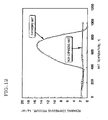
- the cell structure strength is measured by the "isostatic destructive strength test”. This is a test performed by placing the carrier which is the cell structure within a rubber cylindrical container, closing an aluminum plate lid, and placing isotropic pressure thereupon underwater. This is a test for reproducing the compression load weight of the carrier being held by the outer periphery portion of the converter can.
- the isostatic strength is represented by the value of the pressure being applied at the instant that the carrier is destroyed, and is stipulated in JASO Stipulation M505-87 of the automobile stipulations issued by the Society of Automotive Engineers of Japan, Inc.
- a canning structure which takes advantage of external periphery holding of the carrier is used for automobile exhaust gas purification catalytic converters. Of course, the higher the isostatic strength of the carrier is, the better, from the perspective of canning.
- ceramic honeycomb-shaped structures are used for automobile exhaust gas purification catalytic converters, and it has been discovered that in the event that the cell partition thickness is 0.1 mm or less and the opening percentage exceeds 85%, it is extremely difficult to maintain the isostatic strength at 10 kg/cm 2 or higher.
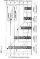
- Fig. 13 shows an example of results obtained by a test performed wherein a pressure-sensitive sheet employing electric contact resistance is introduced between a cordierite ceramic honeycomb structure (106 mm in diameter x 150 mm, with a cell structure of 2.5 mil/ 900 cpsi) and a holding material mat, measuring the compressive pressure at the time of canning by pressing the above into a stainless container (material 409, plate thickness 1.5 mm) or canning by wrapping, and comparing this with the calculated design compressive pressure. With either canning method, the actually-measured maximum compressive pressure valued occurs at the matching part of the mat, exhibiting a value higher than the average compressive pressure.
- the compressive pressure was overall greater at the first half of the mat pressing side as compared to the latter half.
- Tests were also performing with the swaging method and roll forging method, obtaining results similar to those of the wrapping method.
- a commercially-available alumina fiber type non-heat expanding mat was used for the mat.
- the design compressive pressure was calculated from the gap dimensions obtained by subtracting the design values for the external diameter of the carrier from the design values for the internal diameter of the container, and mat bulk density specified in the specification thereof. With either of pressing in or wrapping, the actually measured average values for compressive pressure were almost the same as the design compressive pressure, but the actually measured maximum values for compressive pressure were far higher than the average compressive pressure, markedly protruding.
- honeycomb structure may be destroyed by locally great holding compressive pressure since the compressing pressure acting on the outer periphery portion or the honeycomb structure is not uniform, due to the gap between the honeycomb structure and the metal container not being constant owing to the outer form precision of the honeycomb structure, and the shifting of the holding material at the time of mounting the honeycomb structure within the metal container.
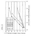
- Fig. 14 shows the relation between the design compressive pressure at the maximum gap position and minimum gap position, and the actually measure canning compressive pressure, according to tests made to find the effects of the amount of deformation of the outer diameter of the structure on the canning compressive pressure, wherein a commercially-available alumina fiber type non-heating expansion mat (plane density of 1,200 g/m 2 ) was wrapped onto a solid aluminum cylinder which had been intentionally deformed by eccentric working of the outer diameter (actually-measured average diameter 103 mm, maximum diameter 104.3 mm, minimum diameter 102.3 mm, length 120 mm), and performing press-in canning of the above article into a stainless steel container (inner diameter 110.9 mm, working tolerance ⁇ 0.3 mm).
- the gap greatly changes owing to the outer diameter precision of the structure, and the compressive pressure also changes according to this.
- the compressive pressure was at a high value of 4.5 kg/cm 2 at the mat mating face.
- the present invention has been made in light of the above-described conventional problems, and accordingly, it is an object thereof to provide a cell structure mounting container and an assemble thereof wherein, in the actual usage temperature range of a catalytic converter and the like, change in compressive pressure on the cell structure within the metal container is small, and the compressive pressure distribution is uniform, thereby preventing destruction of the cell structure.
- a cell structure mounting container mounting a cell structure within a metal container wherein the cell structure is held within the metal container by providing a compressed resilient material having heat-resistance and cushioning characteristics between the outer periphery portion of the cell structure and the metal container, in a compressed state, and wherein the compressed resilient material having heat-resistance and cushioning characteristics is a heat-resistant low thermal expansion material containing either ceramic fiber or ceramic fiber and heat-resistant metal fiber, having compression characteristics which do not greatly fluctuate within a usage temperature range, with the compression force acting upon the periphery portion of the cell structure not changing greatly, preferably acting essentially uniformly upon the entire periphery portion of the cell structure.
- the compressed resilient material is preferably provided between the periphery portion of the cell structure and the metal container in without having a mating face such as with a mat or blanket.
- this cell structure mounting container is suitably used for purification automobile exhaust gasses.
- the compressed resilient material having heat-resistance and cushioning characteristics preferably is a non-intumescent material essentially not containing vermiculite or a heat expansion material containing small amounts of vermiculite; said material comprising a ceramic fiber containing as a primary component thereof at least one member selected from the group consisting of alumina, high alumina, mullite, silicon carbide, silicon nitride, zirconia, and titania or a compound of those materials.
- said ceramic honeycomb mounting container is preferably produced by covering the periphery portion of a cell structure beforehand with the compressed resilient material, incasing the resultant cell structure in a metal container in such manner that a compressive pressure is applied to the cell structure, thereby holding the cell structure within the metal container.
- the means for mounting the cell structure within the metal container and applying compressive pressure to the cell structure via the compressed resilient material preferably is one of clamshell, stuffing, tornqiuet, swaging, or roll forging.
- the cell structure is held within the metal container, preferably by filling the gap between the metal container and the cell structure with the compressed resilient material following positioning the cell structure within the space in the metal container, and applying external pressure from the outer side of the metal container.
- any type of metal containers may be used as far as such a metal container can store the cell structure by virtue of any one of the above-mentioned mounting methods for the cell structure under application of compressive pressure thereto.
- a can type container, swaging type, roll forging type, or the like may be given as a non-limitative example.
- the compressed resilient material preferably is filled in the state of the cell structure at a low temperature being positioned within the metal container at a high temperature, following which the entire article is cooled to room temperature, thereby applying compressive pressure to the cell structure, and also preferably the compressed resilient material and heat-resistant metal wire mesh are introduced between the cell structure and the metal container in a mixed state while applying compressive pressure to the cell structure.
- the wire mesh is preferably positioned on the periphery portion of the cell structure beforehand, with the compressed resilient material being applied from the periphery portion so as to fill in the wire mesh entirely.
- the cell structure and the wire mesh are preferably placed within the metal container beforehand such that the wire mesh is introduced between the metal container and the cell structure, and the compressed resilient material is filled in between the metal container and the cell structure.
- the cell structure is preferably a ceramic honeycomb structure having a plurality of cell channels formed of a plurality of partitions, wherein the cell partitions are 0.1 mm or less in thickness, and the percentage of opening is 85% or more.
- an outer wall forming an outer circumference outline for the cell structure is preferably formed at the periphery portion of the ceramic honeycomb structure, wherein the thickness of the outer wall is at least 0.05 mm.
- the periphery plane of the cell structure outer wall is preferably covered with a heat-resistant low thermal expansion material which essentially does not have compression resilience.
- the ceramic honeycomb structure preferably comprises a main body which does not have an outer wall and has the cell partitions exposed to the outer periphery portion of the honeycomb structure, and a shell part of heat-resistant material containing ceramic fiber positioned at the periphery portion of the main body so as to also exist between exposed cell partitions.
- the heat-resistant material layer containing the ceramic fiber at the shell portion preferably has compression resilience, thereby manifesting compressive pressure for holding the honeycomb structure within the metal container.
- the cell structure may be a foam structure formed of a ceramic material or a heat-resistant metal material, instead of the ceramic honeycomb structure.
- the cell structure preferably comprises one heat-resistant material selected from the group of cordierite, alumina, mullite, zirconia, zirconium phosphate, aluminum titanate, silicon carbide, silicone nitride, titania, stainless steel materials, nickel materials, and the like or any compound of them.
- the cell structure is preferably stored in and held within the metal container after loading the cell structure with a catalyst component, in the event of using the cell structure mounting container as a catalytic converter. Also, loading a catalyst component by the cell structure following mounting and holding the cell structure in and by the metal container is also preferable.
- a cell structure mounting container assembly comprising a plurality of the cell structure mounting containers holding the cell structures and arrayed serially along the direction of fluid flow within a single metal outer cylinder, wherein, of the plurality of cell structure mounting containers, at least the cell structure mounting containers at the front side and the rear side are fixed to the metal outer cylinder by laser beam welding from the outer periphery portion of the metal outer cylinder.
- the present invention relates to a cell structure mounting container with a cell structure stored inside a metal container, which involves holding the cell structure within the metal container by introducing a compressed resilient material having heat-resistance and cushioning characteristics in a compressed state between the periphery portion of the cell structure and the inner face of the metal container.
- the compressed resilient material having heat-resistance and cushioning characteristics which is used is a heat-resistant low thermal expansion material containing either ceramic fiber or ceramic fiber and heat-resistant metal fiber, having compression characteristics which do not greatly fluctuate within a usage temperature range, with the compression force acting upon the periphery portion of the cell structure not changing greatly, and further acting essentially uniformly upon the entire periphery portion of the cell structure.
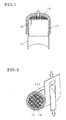
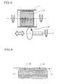
- Fig. 1 the press-in method shown in Fig. 1, the wrapping method shown in Fig. 2, or the clamshell method shown in Fig. 3, are used as a method for canning. Also performed is a method such as shown in Fig. 4 wherein metal plasticity working technology is applied and compression pressure is externally applied to the metal container 11 by a tap (pressurizing) 12, so as to reduce the outer diameter dimensions of the metal container 11 (this method is known as the swaging method). Further, as shown in Fig. 1, the wrapping method shown in Fig. 2, or the clamshell method shown in Fig. 3, are used as a method for canning. Also performed is a method such as shown in Fig. 4 wherein metal plasticity working technology is applied and compression pressure is externally applied to the metal container 11 by a tap (pressurizing) 12, so as to reduce the outer diameter dimensions of the metal container 11 (this method is known as the swaging method). Further, as shown in Fig.
- a method can be used wherein metal plasticity working is applied and the outer periphery plane of the metal container 11 is reduced by metal plasticity working while rotating the metal container 11 using a jig 18, called the roll forging method, thereby reducing the outer diameter of the metal container and providing compressive pressure.
- the above clamshell, press-in, and wrapping methods wind a compressed resilient holding material (a compressed resilient material) 15 onto the cell structure 14 beforehand, and with the clamshell method, as shown in Fig. 3, an integral container is formed by sandwiching the above article between metal container halves 11a and 11b while applying pressure thereof, and welding the mating faces (flanges) 16a and 16b of the two metal container halves 11a and 11b.
- the press-in method uses a guide 17 to insert the article into the integral container 11 under pressure, as shown in Fig. 1.
- the wrapping method involves applying compresive pressure by wrapping a metal plate 11c onto the article 11c and pulling, as shown in Fig. 2, following which the matching portion on the metal plate 11c is welded and fixed.
- the step of forming a mating face may be omitted by covering in advance the periphery portion surface of the cell structure with a compressed resilient material by coating or the like, instead of using a mat.
- a method suitable for applying compressive pressure is to apply compressive pressure to the cell structure 14 within the can 11 and hold the cell structure 14 therein, without allowing relative positional shifting between the mat and can, as much as possible.
- the can 11 has surrounded the cell structure 14 wrapped with the compressed resilient material 15 before applying compressive pressure, so there is little relative positional shifting between the can 11 and the compressed resilient material 15, a desirable factor.
- positional shifting between the can halves 11a and 11b and the compressed resilient material 15 can be suppressed to a certain extent by making improvements in the method of securing the can wherein the cell structure 14 is sandwiched between the upper and lower split container (can) halves 11a and 11b by bending the can halves 11a and 11b, but this would necessitate the canning device and jigs becoming more complex.
- the pressing method can be employed as a method wherein the cell structure 14 is positioned within the can 11, using the swaging method or roll forming method for the means for applying compressive pressure.
- the cell structure is generally a cordierite ceramic honeycomb structure which has been integrally formed by extrusion and baking, and the precision of the outer diameter changes due to deformations in the process from forming to baking, so this problem involves deformation which is much greater than that of the can.
- the gap is not uniform, and the thickness of the compressed resilient material such as the mat placed around the cell structure is constant, this means that the amount of compression of the mat differs between parts where the gap is small and where the gap is large, and the compressive pressure changes accordingly.
- the periphery portion of the cell structure 14 is preferably worked following forming and baking as shown in Figs.
- the outer diameter precision of the cell structure can be improved, and this can be applied to honeycomb structures used for large-size diesel vehicles exhaust gas purification catalyst carriers or diesel particulate filters (DPF) for trucks, buses, etc., as these have relatively great outer diameter dimensions and outer diameter deformation is greater.
- DPF diesel particulate filters
- the above problem (3) can be solved by improving the outer diameter precision of the cell structure, but can also be solved by optimizing the mat thickness to the gap dimensions. Since it is unrealistic to match the mat thickness to the gap, according to an embodiment of the present invention, instead of using a mat, a compressed resilient material is filled in the gap between the can and the cell structure instead of the mat. Thus, the thickness of the compressed resilient material can be made to match the gap dimensions.
- a method may be used wherein following applying the compressed resilient material 15 to the outer circumference plane of the carrier 14 which is the cell structure, and following pressing the carrier 14 into the metal container 11 in a state that compressive pressure is essentially not placed upon the carrier outer periphery portion, the metal container 11 is pressurized using a tap 12. Further, a method may be used wherein the cell structure is positioned within a cylindrical mold, and the gap between the mold and the cell structure is filled. With any of these methods, performing thermal processing following coating or filling of the compressed resilient material causes the water or organic binder to evaporate or be decomposed, following which compressive pressure is applied to perform canning.
- a method may be used wherein the carrier 14 is positioned within the metal container 11 in a state wherein compressive pressure is essentially not applied, following which the metal container 11 is rotated while reducing the outer periphery portion surface of the metal container 11 using a working jig 18 by plasticity working, i.e., the roll forging method, thereby providing compressive pressure.
- the swaging method and roll forging method are both application examples of plasticity working which is conventionally known. From the above, the wrapping method, swaging method, or roll forging method are more preferable for preventing shifting of the compressed resilient material and manifesting more uniform compression compressive pressure characteristics.
- the compressed resilient material used with the present invention is preferably a non-intumescent material essentially not containing vermiculite or a heat expansion material containing small amounts of vermiculite.
- this compressed resilient material preferably has as the primary component thereof ceramic fiber comprising at least one or a compound of a plurality of materials selected from the following group: alumina, high alumina, mullite, silicon carbide, silicon nitride, zirconia, and titania.
- a small amount of inorganic binder is added to this, 2 to 20 parts of binder to 100 parts of fiber material by dry weight ratio, and further an appropriate amount of water is added and the pH thereof is adjusted, thus providing the material with flexibility and viscosity suitable for coating or filling.
- flexible ceramic long fibers with fiber diameters between around 2 to 6 ⁇ m is suitable for obtaining compression resilience.
- mixing in fibers with greater diameter into the fine fibers enables withstanding the compressive pressure, which can provide an advantage in that breaking of fine fibers with flexibility is suppressed while maintaining flexibility.
- alumina silicate can be used instead of the above-described, but the essential glass nature means that there is heat shrinkage at high-temperature environments, and crystalline fibers are preferable with regard to this point.
- crystalline components may precipitate within the fibers, leading to deterioration of the material under high-temperature environments. Accordingly, care must be taken regarding high-temperature heating characteristics for glass material.
- inorganic binders examples include water-glass, colloidal silica, colloidal alumina, and so forth.
- ceramic powders such as cordierite, silicon nitride, SiC, etc.
- Organic binders can be used as well as inorganic binders, from the perspective of binding. It is conventionally known that using organic binders such as emulsion latex and the like can exhibit advantages of suppressing shifting of the mat at the time of canning, in addition to binding. Whether there essentially is compressed resilience or not is determined from the characteristics of the ceramic fiber included (whether flexible or not) and the ratio of the fiber to the binder.
- the bulk density of the compressed resilient material containing ceramic fibers is preferably 0.05 to 0.3 g/cm 3 in an uncompressed state, and the greater the ratio of the fiber becomes, the higher the compression resilience capabilities are, and the lower the ratio of the fiber becomes, the lower the compression resilience capabilities are.
- the amount of vermiculite contained therein should be small, preferably within 15% by weight, in order to suppress the heat expansions characteristics as much as possible to reduce change in compressive pressure. However, in the event that the usage temperature exceeds 800°C, addition of small amounts of vermiculite becomes fairly meaningless, and thus is undesirable.
- Cushioning characteristics can be increased by mixing appropriate amounts of heat-resistant metal fibers in, formed of such as stainless steels, nickels, tungsten, molybdenum, and so forth.
- heat-resistant metal fibers formed of such as stainless steels, nickels, tungsten, molybdenum, and so forth.
- high cushioning characteristics can be obtained by coating non-compression resilient, i.e., an essentially non-cushioning, heat-resistant and low-expansion material on the outer periphery portion of the cell structure, and further coating a heat-resistant and low-expansion compressed resilience material having cushioning characteristics containing ceramic fibers or ceramic fibers and heat-resistant metal fibers thereupon, or sequentially layering ceramic fibers or ceramic fibers and heat-resistant metal fibers toward the outside of the non-compression resilient layer in the form of fiber sheets, or like methods, thereby sequentially increasing the amount to yield a layered placement (inclined structure).
- non-compression resilient i.e., an essentially non-cushioning, heat-resistant and low-expansion material on the outer periphery portion of the cell structure
- a heat-resistant and low-expansion compressed resilience material having cushioning characteristics containing ceramic fibers or ceramic fibers and heat-resistant metal fibers thereupon, or sequentially layering ceramic fibers or ceramic fibers and
- applying a non-compression resilient material to the outer periphery portion of the carrier 14 to form an outer wall 31 allows the precision of the outer diameter to the cell structure to be suitable, and change in the gap between the metal container (casing) and the cell structure can be reduced, thereby reducing change in the compressive pressure acting on the carrier at the time of canning. Also, compressive pressure change can be reduced so the compressive pressure can be set to a low value, enabling canning of cell structures with relatively low strength.
- a non-compression resilient material can be obtained by either using fibers with low flexibility, or reducing the ratio of fibers.
- a non-compression resilient material can be obtained by either using fibers with low flexibility, or reducing the ratio of fibers.
- Japanese Patent No. 2,613,729 Japanese Patent No. 2,613,729
- binding characteristics and an appropriate viscosity can be obtained by using ceramic fibers and ceramic particles as a skeleton material therefor and adding inorganic binder and water thereto, thereby obtaining a non-compression resilient material which can be coated onto the article.
- compressed resilient material 15 and heat resistant metal wire mesh 20 are used in a mixed state (i.e., a mixed material), and the mixed material is introduced between the cell structure 14 and the inner face of the metal container 11 while providing compressive pressure to the cell structure 14, thereby enabling the cushioning characteristics of the compressed resilient material to be improved, using the spring characteristics of the wire mesh.
- a mixed state i.e., a mixed material
- the wire mesh is positioned around the cell structure beforehand and the compressed resilient material is filled in from around the overall cell structure, or a method wherein the cell structure and the wire mesh are placed within the metal container such that the wire mesh is introduced between the structure and the metal container, following which the compressed resilient material is filled in between the metal container and the structure.
- a compressed resilient holding structure comprising primarily metal wire mesh has been conventionally known, but there have been problems of the holding force thereof deteriorating due to the resilience capabilities of the metal material being lost from high exhaust gas temperatures and the wire mesh loosing its springiness, and accordingly holding structures primarily using expansion mats have come to be mainstream.
- non-heat expanding mats are advantageous in that the compressive pressure changes from temperature change are small, but the compression resilience capabilities are relatively small, and the cushioning characteristics may be lower than those of heat expanding mats containing vermiculite and metal wire mesh, if temperature priorities are ignored.
- non-intumescent holding materials with metal wire mesh in order to supplement the low cushioning characteristics of the non-intumescent holding materials. That is to say, as described above, including wire mesh within the layer of the non-intumescent material suppresses increase in temperature of the wire mesh by the non-intumescent holding material absorbing the heat transmitted or radiated from the cell structure heated by the exhaust gasses, thus preventing the wire mesh from loosing its springiness. Also, increasing the cushioning characteristics allows the amount of compression necessary for obtaining the required compressive pressure to be reduced, thus allowing the thickness of the compression expansion holding material layer to be reduced, thereby reducing the gap between the metal container and the cell structure. Hence, the effective cross-sectional area of the cell structure for passage of exhaust gas can be increased, thereby reducing pressure loss.
- the outer periphery portion of the honeycomb structure 14 which is the cell structure is worked to remove low-strength portions where cell deformations exist, following which a non-compression resilient, heat-resistant, and low-heat-expansion material is coated on the outer periphery portion of the structure, so as to form a periphery portion coating portion 22, thereby strengthening the periphery portion of the honeycomb structure (carrier) and improving the isostatic strength.
- the periphery portion coating portion 22 can be formed by methods such as coating a heat-resistant and low-expansion compressed resilience material having cushioning characteristics containing ceramic fibers or ceramic fibers and heat-resistant metal fibers around the non-compression resilient material, or sequentially layering ceramic fibers or ceramic fibers and heat-resistant metal fibers toward the outside of the non-compression resilient layer in the form of fiber sheets, or like methods, thereby sequentially increasing the amount to yield a layered placement (inclined structure), and consequently obtaining high cushioning characteristics.
- the outer diameter precision of the honeycomb structure is improved by working and coating the periphery portion thereof, and the gap between the honeycomb structure and the metal container can be reduced which reduces the compressive pressure, so great increases or decreases the compressive pressure can be avoided.
- the periphery portion of the honeycomb structure removes the outer wall, which causes the cell partitions to be exposed, and the periphery plane of the structure becomes rough due to these partitions.
- the no-compression resilient material should be coated so as to fill in between the cell partitions and fill in the roughness.
- heat expanding material exists between cell partitions, the partitions will be pressed and broken when heated due to the expanding, so non-heat-expanding materials must be used for a honeycomb structure while has lost the outer wall due to periphery portion working.
- Enabling the canning compressive pressure to be set lower by coating the periphery portion of the ceramic honeycomb structure so as to strengthen the periphery portion of the structure and also improve the precision of the outer diameter of the carrier means that not only is non-heat expanding material applicable as the compressed resilient material, but also heat expanding material containing vermiculite can be applied as well. However, the amount of vermiculite should be kept as small as possible, in order to avoid sudden increase in compressive pressure due to heat expansion. Also, an arrangement may be made wherein the non-heat expanding compressed resilient material is directly fill and applied to the periphery portion of the structure of which the periphery portion has been worked. Excellent outer diameter precision of the structure enabling setting the gap between the metal container and the structure means that the effective cross-sectional area of the honeycomb structure for passage of exhaust gas can be increased, thereby furthering reduction of pressure loss.
- a method may be employed wherein the cell structure is held in the metal container before being caused to carry the catalyst, and then later carrying the catalyst. According to this method, nicking or damaging of cell structures during the process of carrying the catalyst can be avoided.
- the cell structure may be a foam structure formed of a ceramic material or a heat-resistant metal material, instead of the honeycomb structure.
- the material of the cell structure may be one or a compound of a plurality of materials selected from the following group of heat-resistant materials: cordierite, alumina, mullite, zirconia, zirconium phosphate, aluminum titanate, silicon carbide, silicone nitride, titania, stainless steel materials, nickel materials, and the like, which is effective for structurally weak structures with thin cell partitions.
- the cell shape of the honeycomb structure formed by extrusion may be triangular, quadrangular, hexagonal, or round, as shown in Fig. 10, and generally a square shape which is a type of quadrangular shape is used, but recently use of hexagonal shapes becoming more commonplace, as well.
- Table 1 shows examples of types of cell structures.
- a cell structure mounting container and an assembly thereof is provided, the assembly comprising cell structure mounting containers 25 holding cell structures 14 and arrayed serially within a single metal sleeve 27, which forms a catalytic converter wherein there is little change in compressive pressure on the cell structure within the metal container of the cell structure mounting container under the usage temperature range, and the compressive pressure distribution thereof is made to be uniform so as to prevent damage to the cell structure.
- At least the cell structure mounting container 25a positioned at the front side and the cell structure mounting container 25b positioned at the rear side of the metal sleeve 27 among the series of cell structure mounting containers 25 are fixed to the metal sleeve 27 by laser beam welding at predetermined positions 28 of the outer periphery portion of the metal sleeve 27.
- Laser beam welding is capable of focusing energy on a local spot, so effects of heat to the areas surrounding the welding potion can be suppressed, thereby avoiding heat damage to the compressed resilient material.
- Table 2 and Fig. 11 shown the results of comparing canning by the conventional method (First comparative example) and canning according to the present invention (First through Fourth embodiments) under the same design conditions of canning design compressive pressure of 3 kg/cm 2 , and the compressed resilient material and cell structure shown in Table 2.
- the honeycomb structures were all subjected to screening at pressure of 10 kg/cm 2 or 5 kg/cm 2 using an isostatic testing device, and only the products without abnormalities were used for the canning test.
- the same tests were performed for the other honeycomb structures which are the cell structures, and no cell structure damage was observed in any of these.
- the design compressive pressure and the actual canning compressive pressure were almost the same, showing that canning according to design could be realized.
- canning can be performed without any damage problems by setting the design compressive pressure lower accordingly.
- the second comparative example which is the conventional example
- water was added to a mixture of alumina fiber 45% (dry mass percentage), inorganic binder 15%, and vermiculite 40%, and kneaded.
- the resulting heat expansion material was coated to the periphery portion of the honeycomb structure, dried, and canned by wrapping. This was used as a sample for the punching test.
- An electric furnace was attached to the testing device, the canned sample was set into a jig in the electric furnace, and while maintaining a predetermined temperature, the lead for punching the honeycomb structure with a silica rod was measured. A punching load of 5 kgf or higher is judged to be suitable.
- the sample Prior to the punching test, the sample was subjected to 100 cycles of heating/cooling in a propane gas burner testing device, with each cycle consisting of 10 minutes at 950°C and 10 minutes at 100°C.
- the canning samples according to the present invention (fifth and sixth embodiments) were tested in the same manner and compared, the results of which are shown in Table 3.
- Heating/cooling vibration testing was also performed wherein vibrations are applied under a constant condition of 200 Hz while undergoing 10 cycles of heating/cooling with each cycle consisting of 5 minutes at 900°C and 5 minutes at 100°C. Whether or not the positional shifting of the honeycomb structure (106 mm in diameter x 150 mm) within the metal container following the testing was within the tolerance range was used for judging whether the samples passed the test.
- a cell structure mounting container and an assembly thereof capable of preventing shifting of the compressed resilient material and holding the cell structure within the metal container while maintaining more uniform compressive pressure characteristics, can be provided.
Applications Claiming Priority (2)
| Application Number | Priority Date | Filing Date | Title |
|---|---|---|---|
| JP2000098817 | 2000-03-31 | ||
| JP2000098817A JP2001280124A (ja) | 2000-03-31 | 2000-03-31 | セル構造体収納容器及びそのアッセンブリ |
Publications (2)
| Publication Number | Publication Date |
|---|---|
| EP1138892A2 true EP1138892A2 (de) | 2001-10-04 |
| EP1138892A3 EP1138892A3 (de) | 2003-10-15 |
Family
ID=18613257
Family Applications (1)
| Application Number | Title | Priority Date | Filing Date |
|---|---|---|---|
| EP01302637A Withdrawn EP1138892A3 (de) | 2000-03-31 | 2001-03-21 | Befestigungsbehälter einer Zellstruktur und dadurch hergestellter Zusammenbau |
Country Status (6)
| Country | Link |
|---|---|
| US (1) | US20010036427A1 (de) |
| EP (1) | EP1138892A3 (de) |
| JP (1) | JP2001280124A (de) |
| KR (1) | KR100401908B1 (de) |
| CN (1) | CN1315615A (de) |
| CA (1) | CA2340272A1 (de) |
Cited By (4)
| Publication number | Priority date | Publication date | Assignee | Title |
|---|---|---|---|---|
| WO2003082467A1 (fr) * | 2002-03-28 | 2003-10-09 | Ngk Insulators, Ltd. | Corps structurel cellulaire, procede de fabrication d'un corps structurel cellulaire et corps structurel de catalyseur |
| DE10242283A1 (de) * | 2002-09-12 | 2004-03-25 | J. Eberspächer GmbH & Co. KG | Vorrichtung und Verfahren zum Anpressen eines Lagermantels an einen Monolithen |
| EP2077155A3 (de) * | 2002-06-17 | 2009-09-16 | Hitachi Metals, Ltd. | Keramische Wabenstruktur, Herstellungsverfahren dafür und dazu verwendetes Beschichtungsmaterial |
| DE102014108429A1 (de) | 2014-06-16 | 2015-12-17 | Tenneco Gmbh | Vorrichtung und Verfahren zum Kalibrieren |
Families Citing this family (40)
| Publication number | Priority date | Publication date | Assignee | Title |
|---|---|---|---|---|
| JP4810721B2 (ja) * | 2000-08-02 | 2011-11-09 | イビデン株式会社 | 燃料電池用改質器の製造方法 |
| ES2248556T3 (es) * | 2001-05-18 | 2006-03-16 | Hess Engineering, Inc. | Metodo y aparato para fabricar un convertidor catalitico. |
| DE10293166D2 (de) * | 2001-07-19 | 2004-07-01 | Emitec Emissionstechnologie | Feder-Dämpfer-System eines Wabenkörpers und dessen Herstellung |
| JP4282960B2 (ja) | 2001-08-30 | 2009-06-24 | 日本碍子株式会社 | 高強度ハニカム構造体、その成形方法及びハニカム構造コンバーター |
| JP3999001B2 (ja) * | 2002-03-08 | 2007-10-31 | 日本碍子株式会社 | ハニカム構造体及びそれを収納してなるキャニング構造体 |
| JP2004067467A (ja) * | 2002-08-08 | 2004-03-04 | Ngk Insulators Ltd | セラミックハニカム構造体 |
| AU2003275215A1 (en) | 2002-09-30 | 2004-04-23 | Unifrax Corporation | Exhaust gas treatment device and method for making the same |
| RU2388522C2 (ru) | 2004-06-29 | 2010-05-10 | Юнифрэкс Корпорейшн | Устройство для обработки отходящих газов и способ его изготовления |
| US7393386B2 (en) * | 2004-10-06 | 2008-07-01 | Fleetguard, Inc. | Exhaust aftertreatment filter with residual stress control |
| JP2006255542A (ja) * | 2005-03-16 | 2006-09-28 | Ngk Insulators Ltd | セラミックハニカム構造体 |
| KR100836059B1 (ko) * | 2006-03-31 | 2008-06-09 | 주식회사 엘지화학 | 점토를 포함하는 세라믹 필터 및 그 제조 방법 |
| WO2010024920A1 (en) | 2008-08-29 | 2010-03-04 | Unifrax I Llc | Mounting mat with flexible edge protection and exhaust gas treatment device incorporating the mounting mat |
| BRPI0921839A2 (pt) * | 2008-11-11 | 2016-01-12 | Tenneco Automotive Operating | unidade catalítica para tratamento de gás de escape e métodos de fabricação para estas unidades |
| WO2010074711A2 (en) | 2008-12-15 | 2010-07-01 | Unifrax I Llc | Ceramic honeycomb structure skin coating |
| JP5679645B2 (ja) * | 2009-02-03 | 2015-03-04 | カルソニックカンセイ株式会社 | 金属触媒担体及びその製造方法 |
| EP2419613B1 (de) | 2009-04-17 | 2016-08-17 | Unifrax I LLC | Abgasverarbeitungsvorrichtung |
| GB0906837D0 (en) | 2009-04-21 | 2009-06-03 | Saffil Automotive Ltd | Mats |
| CN102713191B (zh) | 2009-08-10 | 2016-06-22 | 尤尼弗瑞克斯I有限责任公司 | 可变基重垫或预型件以及废气处理装置 |
| WO2011019394A1 (en) | 2009-08-14 | 2011-02-17 | Unifrax I Llc | Multiple layer substrate support and exhaust gas treatment device |
| US9174169B2 (en) | 2009-08-14 | 2015-11-03 | Unifrax I Llc | Mounting mat for exhaust gas treatment device |
| US8071040B2 (en) | 2009-09-23 | 2011-12-06 | Unifax I LLC | Low shear mounting mat for pollution control devices |
| CN102575552B (zh) | 2009-09-24 | 2016-03-16 | 尤尼弗瑞克斯I有限责任公司 | 多层垫和废气处理装置 |
| WO2011067598A1 (en) | 2009-12-01 | 2011-06-09 | Saffil Automotive Limited | Mounting mat |
| FR2953151B1 (fr) * | 2009-12-01 | 2014-06-13 | Air Liquide | Reacteur catalytique comprenant une structure alveolaire catalytique et des elements optimisant le contact de cette structure alveolaire avec la paroi interne du reacteur |
| CN102753795B (zh) | 2009-12-17 | 2016-02-17 | 尤尼弗瑞克斯I有限责任公司 | 微球体在废气处理装置安装垫中的用途 |
| KR101796329B1 (ko) | 2009-12-17 | 2017-11-09 | 유니프랙스 아이 엘엘씨 | 배기 가스 처리 기기용 장착 매트 |
| CN102770630B (zh) | 2009-12-17 | 2016-02-17 | 尤尼弗瑞克斯I有限责任公司 | 用于污染控制装置的多层安装垫 |
| WO2011115979A2 (en) | 2010-03-17 | 2011-09-22 | Baldwin Filters, Inc. | Fluid filter |
| WO2011115973A2 (en) * | 2010-03-17 | 2011-09-22 | Baldwin Filters, Inc. | Fluid filter |
| US8765069B2 (en) | 2010-08-12 | 2014-07-01 | Unifrax I Llc | Exhaust gas treatment device |
| US8349265B2 (en) | 2010-08-13 | 2013-01-08 | Unifrax I Llc | Mounting mat with flexible edge protection and exhaust gas treatment device incorporating the mounting mat |
| US9120703B2 (en) | 2010-11-11 | 2015-09-01 | Unifrax I Llc | Mounting mat and exhaust gas treatment device |
| US9924564B2 (en) | 2010-11-11 | 2018-03-20 | Unifrax I Llc | Heated mat and exhaust gas treatment device |
| CN103742237B (zh) * | 2014-01-15 | 2016-05-11 | 夏琦 | 柴油内燃机排气捕集器 |
| PL3262287T3 (pl) | 2015-02-24 | 2020-07-27 | Unifrax I Llc | Mata izolacyjna odporna na wysokie temperatury |
| JP6535530B2 (ja) | 2015-07-09 | 2019-06-26 | 日本碍子株式会社 | ハニカム構造体の製造方法 |
| CN107556012B (zh) * | 2017-08-28 | 2020-02-07 | 洛阳理工学院 | 一种嵌扣式防弹陶瓷片及其制备方法 |
| KR102463474B1 (ko) * | 2018-01-30 | 2022-11-03 | 현대자동차주식회사 | 자동차용 촉매컨버터의 히터커버 장치 |
| US10957935B2 (en) * | 2019-05-14 | 2021-03-23 | TeraWatt Technology Inc. | Isostatic press devices and processes for cylindrical solid-state batteries |
| CN115007091B (zh) * | 2022-06-06 | 2024-02-09 | 杨文丽 | 一种用于精细化工生产的管道反应器 |
Citations (5)
| Publication number | Priority date | Publication date | Assignee | Title |
|---|---|---|---|---|
| US4093423A (en) * | 1972-10-03 | 1978-06-06 | Volkswagenwerk Aktiengesellschaft | Catalytic device for the catalytic purification of exhaust gases |
| GB2268695A (en) * | 1992-07-18 | 1994-01-19 | A C Rochester Australia Limite | Catalytic converter mesh seals |
| EP0643204A2 (de) * | 1993-09-03 | 1995-03-15 | Ngk Insulators, Ltd. | Keramische wabenförmige Katalysatoreinrichtung |
| US5811063A (en) * | 1993-04-22 | 1998-09-22 | Unifrax Corporation | Mounting mat for fragile structures such as catalytic converters |
| EP0947673A2 (de) * | 1998-03-30 | 1999-10-06 | Ngk Insulators, Ltd. | Verfahren zum Zusammenbau eines katalytischen Konverters mit einer keramischen Honigwabenstruktur und Stützelement hierfür |
Family Cites Families (10)
| Publication number | Priority date | Publication date | Assignee | Title |
|---|---|---|---|---|
| US643423A (en) * | 1897-11-08 | 1900-02-13 | Nils Nilson | Automatic weighing-scale. |
| US3771967A (en) * | 1971-12-14 | 1973-11-13 | Tenneco Inc | Catalytic reactor with monolithic element |
| JPS5817335B2 (ja) * | 1975-04-10 | 1983-04-06 | トヨタ自動車株式会社 | 排気ガス浄化用の一体型触媒コンポ−ネントの製造方法 |
| FR2585071B1 (fr) * | 1985-07-16 | 1987-11-27 | Peugeot Cycles | Pot d'echappement pour vehicule automobile ou analogue |
| DE8812762U1 (de) * | 1988-10-11 | 1989-06-29 | Emitec Emissionstechnologie | |
| US4963700A (en) * | 1989-04-26 | 1990-10-16 | Minnesota Mining And Manufacturing Company | Closure arrangements for electrical splices |
| US5207989A (en) * | 1991-03-22 | 1993-05-04 | Acs Industries, Inc. | Seal for catalytic converter and method therefor |
| US5629067A (en) * | 1992-01-30 | 1997-05-13 | Ngk Insulators, Ltd. | Ceramic honeycomb structure with grooves and outer coating, process of producing the same, and coating material used in the honeycomb structure |
| DE4233404C2 (de) * | 1992-10-05 | 1994-08-18 | Degussa | Monolithischer Metallträgerkatalysator mit einem katalytisch beschichteten Wabenkörper |
| US5686039A (en) * | 1995-06-30 | 1997-11-11 | Minnesota Mining And Manufacturing Company | Methods of making a catalytic converter or diesel particulate filter |
-
2000
- 2000-03-31 JP JP2000098817A patent/JP2001280124A/ja not_active Withdrawn
-
2001
- 2001-01-22 CN CN01103058A patent/CN1315615A/zh active Pending
- 2001-03-06 US US09/799,054 patent/US20010036427A1/en not_active Abandoned
- 2001-03-09 CA CA002340272A patent/CA2340272A1/en not_active Abandoned
- 2001-03-21 EP EP01302637A patent/EP1138892A3/de not_active Withdrawn
- 2001-03-30 KR KR10-2001-0016822A patent/KR100401908B1/ko not_active IP Right Cessation
Patent Citations (5)
| Publication number | Priority date | Publication date | Assignee | Title |
|---|---|---|---|---|
| US4093423A (en) * | 1972-10-03 | 1978-06-06 | Volkswagenwerk Aktiengesellschaft | Catalytic device for the catalytic purification of exhaust gases |
| GB2268695A (en) * | 1992-07-18 | 1994-01-19 | A C Rochester Australia Limite | Catalytic converter mesh seals |
| US5811063A (en) * | 1993-04-22 | 1998-09-22 | Unifrax Corporation | Mounting mat for fragile structures such as catalytic converters |
| EP0643204A2 (de) * | 1993-09-03 | 1995-03-15 | Ngk Insulators, Ltd. | Keramische wabenförmige Katalysatoreinrichtung |
| EP0947673A2 (de) * | 1998-03-30 | 1999-10-06 | Ngk Insulators, Ltd. | Verfahren zum Zusammenbau eines katalytischen Konverters mit einer keramischen Honigwabenstruktur und Stützelement hierfür |
Cited By (9)
| Publication number | Priority date | Publication date | Assignee | Title |
|---|---|---|---|---|
| WO2003082467A1 (fr) * | 2002-03-28 | 2003-10-09 | Ngk Insulators, Ltd. | Corps structurel cellulaire, procede de fabrication d'un corps structurel cellulaire et corps structurel de catalyseur |
| US7410929B2 (en) | 2002-03-28 | 2008-08-12 | Ngk Insulators, Ltd. | Cell structural body, method of manufacturing cell structural body, and catalyst structural body |
| EP2077155A3 (de) * | 2002-06-17 | 2009-09-16 | Hitachi Metals, Ltd. | Keramische Wabenstruktur, Herstellungsverfahren dafür und dazu verwendetes Beschichtungsmaterial |
| DE10242283A1 (de) * | 2002-09-12 | 2004-03-25 | J. Eberspächer GmbH & Co. KG | Vorrichtung und Verfahren zum Anpressen eines Lagermantels an einen Monolithen |
| DE10242283B4 (de) * | 2002-09-12 | 2005-09-08 | J. Eberspächer GmbH & Co. KG | Vorrichtung und Verfahren zum Anpressen einer Lagermatte an einen Monolithen |
| US7137199B2 (en) | 2002-09-12 | 2006-11-21 | J. Eberspächer GmbH & Co. KG | Method of inserting a bearing jacket and a monolith into a pipe |
| DE102014108429A1 (de) | 2014-06-16 | 2015-12-17 | Tenneco Gmbh | Vorrichtung und Verfahren zum Kalibrieren |
| WO2015193244A1 (de) | 2014-06-16 | 2015-12-23 | Tenneco Gmbh | Vorrichtung und verfahren zum kalibrieren |
| DE102014108429B4 (de) * | 2014-06-16 | 2016-03-24 | Tenneco Gmbh | Vorrichtung und Verfahren zum Kalibrieren |
Also Published As
| Publication number | Publication date |
|---|---|
| JP2001280124A (ja) | 2001-10-10 |
| KR100401908B1 (ko) | 2003-10-17 |
| US20010036427A1 (en) | 2001-11-01 |
| EP1138892A3 (de) | 2003-10-15 |
| CN1315615A (zh) | 2001-10-03 |
| KR20010095154A (ko) | 2001-11-03 |
| CA2340272A1 (en) | 2001-09-30 |
Similar Documents
| Publication | Publication Date | Title |
|---|---|---|
| EP1138892A2 (de) | Befestigungsbehälter einer Zellstruktur und dadurch hergestellter Zusammenbau | |
| US7273649B2 (en) | Honeycomb structural body and canning structural body storing the honeycomb structural body | |
| CA2371116C (en) | High temperature mat for a pollution control device | |
| CA2131247C (en) | Ceramic honeycomb catalytic converter | |
| KR100297621B1 (ko) | 세라믹하니캄구조체및세라믹하니캄구조체로된촉매 | |
| EP0824184B1 (de) | Keramischer katalytischer Konverter | |
| KR101145019B1 (ko) | 오염 조절 요소의 유지재 및 오염 조절 장치 | |
| JP2001526115A (ja) | 触媒コンバータの製造方法 | |
| WO1999013204A2 (en) | Method of manufacturing catalytic converter | |
| US7087286B2 (en) | Honeycomb structure and assembly thereof | |
| US7078086B2 (en) | Honeycomb structure and assembly thereof | |
| US6732432B2 (en) | Apparatus and method for forming an exhaust emission control device, and the device formed thereby | |
| Stroom et al. | Systems approach to packaging design for automotive catalytic converters | |
| US20020168304A1 (en) | Devices for managing housing expansion in exhaust emission control devices | |
| US20050214178A1 (en) | Catalytic converter system and method of making the same | |
| EP1308607B1 (de) | Kegelförmige Enden für Vorrichtungen zur Abgasemissionssteuerung und Verfahren zur Herstellung | |
| EP1416132A1 (de) | Vorrichtung zur Abgasemissionssteuerung und Verfahren zu dessen Herstellung | |
| JP3390698B2 (ja) | キャニング構造体 | |
| US20060045824A1 (en) | Gas treatment device and system, and method for making the same | |
| Gulati | Ceramic converter technology for automotive emissions control | |
| Umehara et al. | Design development of high temperature manifold converter using thin wall ceramic substrate | |
| JP2003278537A (ja) | 触媒コンバータ |
Legal Events
| Date | Code | Title | Description |
|---|---|---|---|
| PUAI | Public reference made under article 153(3) epc to a published international application that has entered the european phase |
Free format text: ORIGINAL CODE: 0009012 |
|
| AK | Designated contracting states |
Kind code of ref document: A2 Designated state(s): AT BE CH CY DE DK ES FI FR GB GR IE IT LI LU MC NL PT SE TR |
|
| AX | Request for extension of the european patent |
Free format text: AL;LT;LV;MK;RO;SI |
|
| PUAL | Search report despatched |
Free format text: ORIGINAL CODE: 0009013 |
|
| AK | Designated contracting states |
Kind code of ref document: A3 Designated state(s): AT BE CH CY DE DK ES FI FR GB GR IE IT LI LU MC NL PT SE TR |
|
| AX | Request for extension of the european patent |
Extension state: AL LT LV MK RO SI |
|
| 17P | Request for examination filed |
Effective date: 20031212 |
|
| 17Q | First examination report despatched |
Effective date: 20040121 |
|
| AKX | Designation fees paid |
Designated state(s): DE FR GB IT |
|
| STAA | Information on the status of an ep patent application or granted ep patent |
Free format text: STATUS: THE APPLICATION IS DEEMED TO BE WITHDRAWN |
|
| 18D | Application deemed to be withdrawn |
Effective date: 20050713 |