EP1138871A1 - Wendelbohrer - Google Patents
Wendelbohrer Download PDFInfo
- Publication number
- EP1138871A1 EP1138871A1 EP01810268A EP01810268A EP1138871A1 EP 1138871 A1 EP1138871 A1 EP 1138871A1 EP 01810268 A EP01810268 A EP 01810268A EP 01810268 A EP01810268 A EP 01810268A EP 1138871 A1 EP1138871 A1 EP 1138871A1
- Authority
- EP
- European Patent Office
- Prior art keywords
- knobs
- groove
- twist drill
- drill according
- twist
- Prior art date
- Legal status (The legal status is an assumption and is not a legal conclusion. Google has not performed a legal analysis and makes no representation as to the accuracy of the status listed.)
- Granted
Links
Images
Classifications
-
- E—FIXED CONSTRUCTIONS
- E21—EARTH OR ROCK DRILLING; MINING
- E21B—EARTH OR ROCK DRILLING; OBTAINING OIL, GAS, WATER, SOLUBLE OR MELTABLE MATERIALS OR A SLURRY OF MINERALS FROM WELLS
- E21B10/00—Drill bits
- E21B10/44—Bits with helical conveying portion, e.g. screw type bits; Augers with leading portion or with detachable parts
- E21B10/445—Bits with helical conveying portion, e.g. screw type bits; Augers with leading portion or with detachable parts percussion type, e.g. for masonry
-
- B—PERFORMING OPERATIONS; TRANSPORTING
- B23—MACHINE TOOLS; METAL-WORKING NOT OTHERWISE PROVIDED FOR
- B23B—TURNING; BORING
- B23B51/00—Tools for drilling machines
- B23B51/02—Twist drills
-
- E—FIXED CONSTRUCTIONS
- E21—EARTH OR ROCK DRILLING; MINING
- E21B—EARTH OR ROCK DRILLING; OBTAINING OIL, GAS, WATER, SOLUBLE OR MELTABLE MATERIALS OR A SLURRY OF MINERALS FROM WELLS
- E21B10/00—Drill bits
- E21B10/44—Bits with helical conveying portion, e.g. screw type bits; Augers with leading portion or with detachable parts
-
- B—PERFORMING OPERATIONS; TRANSPORTING
- B23—MACHINE TOOLS; METAL-WORKING NOT OTHERWISE PROVIDED FOR
- B23B—TURNING; BORING
- B23B2226/00—Materials of tools or workpieces not comprising a metal
- B23B2226/75—Stone, rock or concrete
-
- B—PERFORMING OPERATIONS; TRANSPORTING
- B23—MACHINE TOOLS; METAL-WORKING NOT OTHERWISE PROVIDED FOR
- B23B—TURNING; BORING
- B23B2251/00—Details of tools for drilling machines
- B23B2251/40—Flutes, i.e. chip conveying grooves
- B23B2251/406—Flutes, i.e. chip conveying grooves of special form not otherwise provided for
-
- B—PERFORMING OPERATIONS; TRANSPORTING
- B23—MACHINE TOOLS; METAL-WORKING NOT OTHERWISE PROVIDED FOR
- B23B—TURNING; BORING
- B23B2260/00—Details of constructional elements
- B23B2260/112—Projections
Definitions
- the invention relates to a twist drill, which as a drilling tool in a rotating and optionally striking tool device is used, advantageously designed for the impact abrasive removal of rock or stone-like material, such as concrete.
- the helix usually has several helixes with the associated ones Grooves in which the material abrasively removed from the drill head is transported away becomes.
- twist drills are known, for example, from EP0653544B1, which is known as a helix reveals two identical helical gears that run with a constant slope each connect to one of the two cutting edges of the drill head. Furthermore points this twist drill on the radially outer edge of the helical gears, which at the Rotate with its envelope curve to form a cylinder approximately the diameter of the drill, one stepped toothing, which has a radial milling effect. To achieve a The largest possible cross-section of the groove is square up to the drill core.
- the EP339412A2 uses a changing slope along the helix as well additional step-like side surfaces of the spiral passages, which protrude into the groove. The predominantly axially and differently oriented areas lead through the striking stress on the drilling tool, to an alternating acceleration of the removed material and thus to a swirl within the groove, the one Counteracts clumping.
- a disadvantage with such a design of the side surfaces the helical gears is the toothing of the rotating teeth that is given near the envelope Helical gears, which are high in the exposed area of the helix Risk of injury and an unintentional area in the borehole Milling the borehole can result.
- the preparation of such a contour prepares Disadvantages on the side surfaces of the spiral aisles, since these would have to be specially shaped.
- a twist drill for rock which is in the shaft has anchored, radially oriented, brush inserts for cleaning the borehole.
- the Brush inserts either form a kind of interrupted in their arrangement to each other Spiral path or are in the bottom of the groove formed by a spiral path arranged. Due to their function, these brush inserts always extend radially up to the formed by the rotation of the envelope.
- a disadvantage of such filigree Brush inserts made of other materials are their short lifespan, especially in the rough Use in the construction industry.
- the brush inserts arranged inside the groove due to their radial extension to the envelope curve, they also significantly reduce the actual groove cross-section available for removal.
- the object of the invention is to avoid the above disadvantages in the implementation of a long-lasting, safely usable twist drill, which clumps the counteracts abrasively removed material in the groove.
- the knobs formed in the base of the groove are surrounded by the in the radial outside smooth, spiral gears with appropriate rotating use of the twist drill is geometrically protected against unintentional contact, creating a milling effect at the edge of the borehole or a risk to the user is excluded.
- the knobs which are advantageously made of the same material as the drill core of the Twist drills exist, are compact and affect the service life the drilling tool in no way.
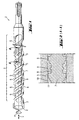
- FIG. 2 has a twist drill 1 with a cutting head 2 equipped with cutting edges 3 axially adjoining helical coil 4 with at least one helical Helical path 5, between which a groove 6 extends into a drill core 7 trains.
- the radially outer surface of the helical gear 5 describes ⁇ upon rotation a cylindrical envelope 8 around the axis of rotation.
- the groove 6 are a plurality of individual, preferably running centrally along the groove 6 Knobs 9 arranged, which protrude radially outwards into the groove 6 without the Envelope 8 to reach.
- These individual knobs 9 are preferably prismatically compact formed with a radial height of 1/10 to 1/2, preferably 1/4, the groove depth, one width of 1/10 to 1/2, preferably 1/4, of the groove width oriented transversely to the spiral path and a length of 1/10 to a double oriented along the spiral path 5, preferably a whole, the groove width, the individual knobs 9 in relation to one another essentially along the groove 6 at a distance of 1/10 to four times the groove width, advantageously equal to the length, along a line or offset from each other and preferably have the same size.
- the individual knobs 9 with their im essential axially oriented longitudinal surfaces, mediated by the axial number of impacts or Vibration v, an acceleration to within the groove 6 from the coil 6 removed, abrasively removed, material 10 and thus avoid through Lumping causes blockage of the twist drill 1 in a borehole 11.
Landscapes
- Engineering & Computer Science (AREA)
- Geology (AREA)
- Life Sciences & Earth Sciences (AREA)
- Mining & Mineral Resources (AREA)
- Mechanical Engineering (AREA)
- Physics & Mathematics (AREA)
- Environmental & Geological Engineering (AREA)
- Fluid Mechanics (AREA)
- General Life Sciences & Earth Sciences (AREA)
- Geochemistry & Mineralogy (AREA)
- Processing Of Stones Or Stones Resemblance Materials (AREA)
- Drilling Tools (AREA)
- Earth Drilling (AREA)
- Polyesters Or Polycarbonates (AREA)
Abstract
Description
- Fig. 1
- als einem Wendelbohrer
- Fig. 2
- als Ausschnitt aus Fig. 1
Claims (10)
- Wendelbohrer (1) für Gestein mit einem Wendel (4) mit wenigstens einer Nut (6), welche von wenigstens einem sich um einen Bohrerkern (7) wendelförmig herumwindenden Wendelgang (5) ausgebildet wird, dadurch gekennzeichnet, dass innerhalb der Nut (6) eine Vielzahl sich radial nach aussen erstreckende Noppen (9) ausgebildet sind, welche teilweise in den Nutquerschnitt eindringen.
- Wendelbohrer nach Anspruch 1, dadurch gekennzeichnet, dass die Noppen (9) die Hüllkurve (8) nicht erreichen.
- Wendelbohrer nach einem der vorherigen Ansprüche, dadurch gekennzeichnet, dass die Noppen (9) vom Grund der Nut (6) ausgebildet sind.
- Wendelbohrer nach einem der vorherigen Ansprüche, dadurch gekennzeichnet, dass die Noppen (9) aus dem selben Material wie der Bohrerkern (7) des Wendelbohrers (1) bestehen.
- Wendelbohrer nach einem der vorherigen Ansprüche, dadurch gekennzeichnet, dass die einzelnen Noppen (9) prismatisch kompakt ausgeformt sind.
- Wendelbohrer nach einem der vorherigen Ansprüche, dadurch gekennzeichnet, dass alle Noppen (9) die selbe Grösse haben.
- Wendelbohrer nach einem der vorherigen Ansprüche, dadurch gekennzeichnet, dass die einzelnen Noppen (9) eine radiale Höhe von 1/4 der Nuttiefe, eine Breite von 1/4 und eine Länge von einem Ganzen der Nutbreite aufweisen.
- Wendelbohrer nach einem der vorherigen Ansprüche, dadurch gekennzeichnet, dass der Abstand zwischen jeweils benachbarten Noppen (9) gleich der Länge der Noppen (9) ist.
- Wendelbohrer nach einem der vorherigen Ansprüche, dadurch gekennzeichnet, dass die Vielzahl der Noppen (9) entlang einer Linie längs der Nut (6) angeordnet sind.
- Wendelbohrer nach einem der Ansprüche 1 bis 8, dadurch gekennzeichnet, dass die Vielzahl der Noppen (9) versetzt zu einer Linie längs der Nut (6) angeordnet sind.
Applications Claiming Priority (2)
| Application Number | Priority Date | Filing Date | Title |
|---|---|---|---|
| DE10015203 | 2000-03-27 | ||
| DE10015203A DE10015203A1 (de) | 2000-03-27 | 2000-03-27 | Wendelbohrer |
Publications (2)
| Publication Number | Publication Date |
|---|---|
| EP1138871A1 true EP1138871A1 (de) | 2001-10-04 |
| EP1138871B1 EP1138871B1 (de) | 2006-07-19 |
Family
ID=7636581
Family Applications (1)
| Application Number | Title | Priority Date | Filing Date |
|---|---|---|---|
| EP01810268A Expired - Lifetime EP1138871B1 (de) | 2000-03-27 | 2001-03-19 | Wendelbohrer |
Country Status (7)
| Country | Link |
|---|---|
| US (1) | US6571890B2 (de) |
| EP (1) | EP1138871B1 (de) |
| JP (1) | JP4782936B2 (de) |
| CN (1) | CN1159142C (de) |
| AT (1) | ATE333563T1 (de) |
| DE (2) | DE10015203A1 (de) |
| DK (1) | DK1138871T3 (de) |
Cited By (1)
| Publication number | Priority date | Publication date | Assignee | Title |
|---|---|---|---|---|
| EP1229210A3 (de) * | 2000-10-27 | 2002-10-16 | HILTI Aktiengesellschaft | Wendelbohrer |
Families Citing this family (6)
| Publication number | Priority date | Publication date | Assignee | Title |
|---|---|---|---|---|
| DE10159014A1 (de) * | 2001-11-30 | 2003-06-18 | Hilti Ag | Gesteinsbohrer |
| EP1475510B1 (de) * | 2003-05-09 | 2010-12-22 | Robert Bosch Gmbh | Bohrer |
| USD557290S1 (en) * | 2006-10-06 | 2007-12-11 | Douglas Melegari | Dry compaction bit for earth boring |
| US7861807B2 (en) * | 2008-12-03 | 2011-01-04 | Black & Decker Inc. | Drill bit including one piece cutting head |
| US9475109B2 (en) | 2013-12-31 | 2016-10-25 | Simpson Strong-Tie Company, Inc. | Method of manufacturing a hollow externally threaded fastener |
| EP3181261A1 (de) * | 2015-12-15 | 2017-06-21 | HILTI Aktiengesellschaft | Herstellungsverfahren, werkzeuggerüst und bohrer |
Citations (10)
| Publication number | Priority date | Publication date | Assignee | Title |
|---|---|---|---|---|
| GB183005A (en) * | 1921-05-20 | 1922-07-20 | Norman Edlow Woods | Improvements in drills |
| SU891250A1 (ru) * | 1980-05-07 | 1981-12-23 | Ленинградский Институт Точной Механики И Оптики | Спиральное сверло |
| EP0339412A2 (de) | 1988-04-23 | 1989-11-02 | Hawera Probst GmbH + Co. | Gesteinsbohrer |
| DE3919095A1 (de) | 1988-07-16 | 1990-01-18 | Hawera Probst Kg Hartmetall | Bohrwerkzeug |
| EP0352215A2 (de) * | 1988-07-16 | 1990-01-24 | Hawera Probst GmbH + Co. | Bohrwerkzeug |
| DE3826239A1 (de) * | 1988-08-02 | 1990-02-08 | Hertel Ag Werkzeuge Hartstoff | Bohrer |
| US5160232A (en) * | 1987-09-10 | 1992-11-03 | Mca Micro Crystal Ag | Drill bit or end mill with grooved flutes |
| EP0653544B1 (de) | 1993-11-11 | 1998-06-17 | HILTI Aktiengesellschaft | Spiralbohrer |
| US5873683A (en) * | 1994-11-10 | 1999-02-23 | Kennametal Hertel Ag Werkzeuge + Hartstoffe | Boring tool |
| DE29724063U1 (de) * | 1997-06-25 | 1999-11-25 | Drebo Werkzeugfabrik Gmbh, 88361 Altshausen | Bohrer |
Family Cites Families (9)
| Publication number | Priority date | Publication date | Assignee | Title |
|---|---|---|---|---|
| JPS52116980A (en) * | 1976-03-26 | 1977-09-30 | Riken Steel Kk | Tip breaker drill and method of manufacturing same |
| SU891220A1 (ru) | 1980-04-02 | 1981-12-23 | Специальное Конструкторское Бюро Алмазно-Расточных И Радиально-Сверлильных Станков | Способ размерной подналадки двух резцов |
| DE3315661C2 (de) * | 1983-03-25 | 1985-03-28 | Günter Horst 7927 Sontheim Röhm | Spannfutter für ein Werkzeug zum Schlagbohren |
| DE3317989A1 (de) * | 1983-05-18 | 1984-11-22 | Hawera Probst Gmbh + Co, 7980 Ravensburg | Bohrwerkzeug |
| US5531553A (en) * | 1990-12-14 | 1996-07-02 | Bickford; Charles | Masonry fixing |
| JPH0569213A (ja) * | 1991-03-25 | 1993-03-23 | Mitsubishi Materials Corp | サブランド付きドリル及びその製造方法 |
| US5456328A (en) * | 1994-01-07 | 1995-10-10 | Dresser Industries, Inc. | Drill bit with improved rolling cutter tooth pattern |
| DE19753731A1 (de) * | 1997-12-04 | 1999-06-10 | Hawera Probst Gmbh | Gesteinsbohrwerkzeug |
| CA2260612C (en) * | 1999-02-03 | 2005-04-26 | Dresser Industries, Inc. | Pneumatic hammer drilling assembly for use in directional drilling |
-
2000
- 2000-03-27 DE DE10015203A patent/DE10015203A1/de not_active Withdrawn
-
2001
- 2001-03-19 EP EP01810268A patent/EP1138871B1/de not_active Expired - Lifetime
- 2001-03-19 AT AT01810268T patent/ATE333563T1/de not_active IP Right Cessation
- 2001-03-19 DK DK01810268T patent/DK1138871T3/da active
- 2001-03-19 DE DE50110469T patent/DE50110469D1/de not_active Expired - Lifetime
- 2001-03-20 CN CNB011118113A patent/CN1159142C/zh not_active Expired - Fee Related
- 2001-03-21 US US09/814,238 patent/US6571890B2/en not_active Expired - Lifetime
- 2001-03-26 JP JP2001087184A patent/JP4782936B2/ja not_active Expired - Fee Related
Patent Citations (10)
| Publication number | Priority date | Publication date | Assignee | Title |
|---|---|---|---|---|
| GB183005A (en) * | 1921-05-20 | 1922-07-20 | Norman Edlow Woods | Improvements in drills |
| SU891250A1 (ru) * | 1980-05-07 | 1981-12-23 | Ленинградский Институт Точной Механики И Оптики | Спиральное сверло |
| US5160232A (en) * | 1987-09-10 | 1992-11-03 | Mca Micro Crystal Ag | Drill bit or end mill with grooved flutes |
| EP0339412A2 (de) | 1988-04-23 | 1989-11-02 | Hawera Probst GmbH + Co. | Gesteinsbohrer |
| DE3919095A1 (de) | 1988-07-16 | 1990-01-18 | Hawera Probst Kg Hartmetall | Bohrwerkzeug |
| EP0352215A2 (de) * | 1988-07-16 | 1990-01-24 | Hawera Probst GmbH + Co. | Bohrwerkzeug |
| DE3826239A1 (de) * | 1988-08-02 | 1990-02-08 | Hertel Ag Werkzeuge Hartstoff | Bohrer |
| EP0653544B1 (de) | 1993-11-11 | 1998-06-17 | HILTI Aktiengesellschaft | Spiralbohrer |
| US5873683A (en) * | 1994-11-10 | 1999-02-23 | Kennametal Hertel Ag Werkzeuge + Hartstoffe | Boring tool |
| DE29724063U1 (de) * | 1997-06-25 | 1999-11-25 | Drebo Werkzeugfabrik Gmbh, 88361 Altshausen | Bohrer |
Non-Patent Citations (1)
| Title |
|---|
| DATABASE WPI Section PQ Week 198244, Derwent World Patents Index; Class P54, AN 1982-P4326E, XP002166465 * |
Cited By (2)
| Publication number | Priority date | Publication date | Assignee | Title |
|---|---|---|---|---|
| EP1229210A3 (de) * | 2000-10-27 | 2002-10-16 | HILTI Aktiengesellschaft | Wendelbohrer |
| US6655479B2 (en) | 2000-10-27 | 2003-12-02 | Hilti Aktiengesellschaft | Twist-drill bit |
Also Published As
| Publication number | Publication date |
|---|---|
| ATE333563T1 (de) | 2006-08-15 |
| US20010023783A1 (en) | 2001-09-27 |
| DE10015203A1 (de) | 2001-10-04 |
| JP2001300934A (ja) | 2001-10-30 |
| DE50110469D1 (de) | 2006-08-31 |
| CN1159142C (zh) | 2004-07-28 |
| DK1138871T3 (da) | 2006-11-13 |
| US6571890B2 (en) | 2003-06-03 |
| CN1315241A (zh) | 2001-10-03 |
| EP1138871B1 (de) | 2006-07-19 |
| JP4782936B2 (ja) | 2011-09-28 |
Similar Documents
| Publication | Publication Date | Title |
|---|---|---|
| EP1259699B1 (de) | Gesteinsbohrer | |
| DE3147099A1 (de) | "drehend arbeitende bohrkrone" | |
| EP1125664A2 (de) | Bohrwerkzeug für Gestein | |
| EP0126409A2 (de) | Bohrwerkzeug | |
| DE4419641A1 (de) | Gesteinsbohrer | |
| EP1184115A1 (de) | Gesteinsbohrer | |
| EP1316669A2 (de) | Gesteinbohrwerkzeug | |
| EP0655547A2 (de) | Gesteinsbohrmeissel mit schraubenförmigem Förderteil | |
| DE10050229C1 (de) | Wendelbohrer für Gestein | |
| DE4011441A1 (de) | Gesteinsbohrer | |
| EP1083294B1 (de) | Bohrwerkzeug | |
| DE3600105A1 (de) | Zahnaerztliche reibahle | |
| EP0653544B1 (de) | Spiralbohrer | |
| DE10015203A1 (de) | Wendelbohrer | |
| DE10159014A1 (de) | Gesteinsbohrer | |
| DE102004016819B3 (de) | Schneidsegment für Werkzeuge | |
| EP1355754B1 (de) | Fräswerkzeug | |
| DE3813849A1 (de) | Gesteinsbohrer | |
| DE19654597B4 (de) | Bohrkrone | |
| DE3540355C2 (de) | Bohrer zum drehschlagenden Bohren | |
| DE2013328B1 (de) | Gesteinsbohrer | |
| EP1190797A1 (de) | Bohrwerkzeug | |
| DE10053343A1 (de) | Wendelbohrer | |
| DE245750C (de) | ||
| DE102023206483A1 (de) | Bohrwerkzeug mit einem Bohrkopf |
Legal Events
| Date | Code | Title | Description |
|---|---|---|---|
| PUAI | Public reference made under article 153(3) epc to a published international application that has entered the european phase |
Free format text: ORIGINAL CODE: 0009012 |
|
| AK | Designated contracting states |
Kind code of ref document: A1 Designated state(s): AT BE CH CY DE DK ES FI FR GB GR IE IT LI LU MC NL PT SE TR |
|
| AX | Request for extension of the european patent |
Free format text: AL;LT;LV;MK;RO;SI |
|
| 17P | Request for examination filed |
Effective date: 20020404 |
|
| AKX | Designation fees paid |
Free format text: AT BE CH CY DE DK ES FI FR GB GR IE IT LI LU MC NL PT SE TR |
|
| GRAP | Despatch of communication of intention to grant a patent |
Free format text: ORIGINAL CODE: EPIDOSNIGR1 |
|
| GRAS | Grant fee paid |
Free format text: ORIGINAL CODE: EPIDOSNIGR3 |
|
| GRAA | (expected) grant |
Free format text: ORIGINAL CODE: 0009210 |
|
| AK | Designated contracting states |
Kind code of ref document: B1 Designated state(s): AT BE CH CY DE DK ES FI FR GB GR IE IT LI LU MC NL PT SE TR |
|
| PG25 | Lapsed in a contracting state [announced via postgrant information from national office to epo] |
Ref country code: IE Free format text: LAPSE BECAUSE OF FAILURE TO SUBMIT A TRANSLATION OF THE DESCRIPTION OR TO PAY THE FEE WITHIN THE PRESCRIBED TIME-LIMIT Effective date: 20060719 Ref country code: FI Free format text: LAPSE BECAUSE OF FAILURE TO SUBMIT A TRANSLATION OF THE DESCRIPTION OR TO PAY THE FEE WITHIN THE PRESCRIBED TIME-LIMIT Effective date: 20060719 Ref country code: IT Free format text: LAPSE BECAUSE OF FAILURE TO SUBMIT A TRANSLATION OF THE DESCRIPTION OR TO PAY THE FEE WITHIN THE PRESCRIBED TIME-LIMIT;WARNING: LAPSES OF ITALIAN PATENTS WITH EFFECTIVE DATE BEFORE 2007 MAY HAVE OCCURRED AT ANY TIME BEFORE 2007. THE CORRECT EFFECTIVE DATE MAY BE DIFFERENT FROM THE ONE RECORDED. Effective date: 20060719 |
|
| REG | Reference to a national code |
Ref country code: GB Ref legal event code: FG4D Free format text: NOT ENGLISH |
|
| REG | Reference to a national code |
Ref country code: CH Ref legal event code: EP |
|
| GBT | Gb: translation of ep patent filed (gb section 77(6)(a)/1977) |
Effective date: 20060725 |
|
| REG | Reference to a national code |
Ref country code: IE Ref legal event code: FG4D Free format text: LANGUAGE OF EP DOCUMENT: GERMAN |
|
| REF | Corresponds to: |
Ref document number: 50110469 Country of ref document: DE Date of ref document: 20060831 Kind code of ref document: P |
|
| PG25 | Lapsed in a contracting state [announced via postgrant information from national office to epo] |
Ref country code: ES Free format text: LAPSE BECAUSE OF FAILURE TO SUBMIT A TRANSLATION OF THE DESCRIPTION OR TO PAY THE FEE WITHIN THE PRESCRIBED TIME-LIMIT Effective date: 20061030 |
|
| REG | Reference to a national code |
Ref country code: SE Ref legal event code: TRGR |
|
| REG | Reference to a national code |
Ref country code: DK Ref legal event code: T3 |
|
| PG25 | Lapsed in a contracting state [announced via postgrant information from national office to epo] |
Ref country code: PT Free format text: LAPSE BECAUSE OF FAILURE TO SUBMIT A TRANSLATION OF THE DESCRIPTION OR TO PAY THE FEE WITHIN THE PRESCRIBED TIME-LIMIT Effective date: 20061219 |
|
| ET | Fr: translation filed | ||
| REG | Reference to a national code |
Ref country code: IE Ref legal event code: FD4D |
|
| PLBE | No opposition filed within time limit |
Free format text: ORIGINAL CODE: 0009261 |
|
| STAA | Information on the status of an ep patent application or granted ep patent |
Free format text: STATUS: NO OPPOSITION FILED WITHIN TIME LIMIT |
|
| 26N | No opposition filed |
Effective date: 20070420 |
|
| BERE | Be: lapsed |
Owner name: HILTI AKTIENGESELLSCHAFT Effective date: 20070331 |
|
| PG25 | Lapsed in a contracting state [announced via postgrant information from national office to epo] |
Ref country code: BE Free format text: LAPSE BECAUSE OF NON-PAYMENT OF DUE FEES Effective date: 20070331 |
|
| PG25 | Lapsed in a contracting state [announced via postgrant information from national office to epo] |
Ref country code: MC Free format text: LAPSE BECAUSE OF NON-PAYMENT OF DUE FEES Effective date: 20070331 |
|
| PG25 | Lapsed in a contracting state [announced via postgrant information from national office to epo] |
Ref country code: GR Free format text: LAPSE BECAUSE OF FAILURE TO SUBMIT A TRANSLATION OF THE DESCRIPTION OR TO PAY THE FEE WITHIN THE PRESCRIBED TIME-LIMIT Effective date: 20061020 |
|
| PG25 | Lapsed in a contracting state [announced via postgrant information from national office to epo] |
Ref country code: AT Free format text: LAPSE BECAUSE OF NON-PAYMENT OF DUE FEES Effective date: 20070319 |
|
| PGFP | Annual fee paid to national office [announced via postgrant information from national office to epo] |
Ref country code: DK Payment date: 20090313 Year of fee payment: 9 |
|
| PGFP | Annual fee paid to national office [announced via postgrant information from national office to epo] |
Ref country code: NL Payment date: 20090303 Year of fee payment: 9 |
|
| PGFP | Annual fee paid to national office [announced via postgrant information from national office to epo] |
Ref country code: CH Payment date: 20090331 Year of fee payment: 9 |
|
| PG25 | Lapsed in a contracting state [announced via postgrant information from national office to epo] |
Ref country code: CY Free format text: LAPSE BECAUSE OF FAILURE TO SUBMIT A TRANSLATION OF THE DESCRIPTION OR TO PAY THE FEE WITHIN THE PRESCRIBED TIME-LIMIT Effective date: 20060719 Ref country code: LU Free format text: LAPSE BECAUSE OF NON-PAYMENT OF DUE FEES Effective date: 20070319 |
|
| PGFP | Annual fee paid to national office [announced via postgrant information from national office to epo] |
Ref country code: SE Payment date: 20090306 Year of fee payment: 9 |
|
| PG25 | Lapsed in a contracting state [announced via postgrant information from national office to epo] |
Ref country code: TR Free format text: LAPSE BECAUSE OF FAILURE TO SUBMIT A TRANSLATION OF THE DESCRIPTION OR TO PAY THE FEE WITHIN THE PRESCRIBED TIME-LIMIT Effective date: 20060719 |
|
| REG | Reference to a national code |
Ref country code: NL Ref legal event code: V1 Effective date: 20101001 |
|
| REG | Reference to a national code |
Ref country code: CH Ref legal event code: PL |
|
| EUG | Se: european patent has lapsed | ||
| REG | Reference to a national code |
Ref country code: DK Ref legal event code: EBP |
|
| PG25 | Lapsed in a contracting state [announced via postgrant information from national office to epo] |
Ref country code: NL Free format text: LAPSE BECAUSE OF NON-PAYMENT OF DUE FEES Effective date: 20101001 |
|
| PG25 | Lapsed in a contracting state [announced via postgrant information from national office to epo] |
Ref country code: CH Free format text: LAPSE BECAUSE OF NON-PAYMENT OF DUE FEES Effective date: 20100331 Ref country code: LI Free format text: LAPSE BECAUSE OF NON-PAYMENT OF DUE FEES Effective date: 20100331 |
|
| PG25 | Lapsed in a contracting state [announced via postgrant information from national office to epo] |
Ref country code: DK Free format text: LAPSE BECAUSE OF NON-PAYMENT OF DUE FEES Effective date: 20100331 |
|
| PG25 | Lapsed in a contracting state [announced via postgrant information from national office to epo] |
Ref country code: SE Free format text: LAPSE BECAUSE OF NON-PAYMENT OF DUE FEES Effective date: 20100320 |
|
| REG | Reference to a national code |
Ref country code: FR Ref legal event code: PLFP Year of fee payment: 16 |
|
| PGFP | Annual fee paid to national office [announced via postgrant information from national office to epo] |
Ref country code: DE Payment date: 20160315 Year of fee payment: 16 |
|
| PGFP | Annual fee paid to national office [announced via postgrant information from national office to epo] |
Ref country code: GB Payment date: 20160316 Year of fee payment: 16 Ref country code: FR Payment date: 20160208 Year of fee payment: 16 |
|
| REG | Reference to a national code |
Ref country code: DE Ref legal event code: R119 Ref document number: 50110469 Country of ref document: DE |
|
| GBPC | Gb: european patent ceased through non-payment of renewal fee |
Effective date: 20170319 |
|
| REG | Reference to a national code |
Ref country code: FR Ref legal event code: ST Effective date: 20171130 |
|
| PG25 | Lapsed in a contracting state [announced via postgrant information from national office to epo] |
Ref country code: FR Free format text: LAPSE BECAUSE OF NON-PAYMENT OF DUE FEES Effective date: 20170331 Ref country code: DE Free format text: LAPSE BECAUSE OF NON-PAYMENT OF DUE FEES Effective date: 20171003 |
|
| PG25 | Lapsed in a contracting state [announced via postgrant information from national office to epo] |
Ref country code: GB Free format text: LAPSE BECAUSE OF NON-PAYMENT OF DUE FEES Effective date: 20170319 |