EP1138557A2 - Front structure of vehicle body securing safety of pedestrians - Google Patents
Front structure of vehicle body securing safety of pedestrians Download PDFInfo
- Publication number
- EP1138557A2 EP1138557A2 EP01107721A EP01107721A EP1138557A2 EP 1138557 A2 EP1138557 A2 EP 1138557A2 EP 01107721 A EP01107721 A EP 01107721A EP 01107721 A EP01107721 A EP 01107721A EP 1138557 A2 EP1138557 A2 EP 1138557A2
- Authority
- EP
- European Patent Office
- Prior art keywords
- bumper
- vehicle body
- upper side
- radiator
- width direction
- Prior art date
- Legal status (The legal status is an assumption and is not a legal conclusion. Google has not performed a legal analysis and makes no representation as to the accuracy of the status listed.)
- Granted
Links
- 239000011358 absorbing material Substances 0.000 claims abstract description 44
- 210000003141 lower extremity Anatomy 0.000 description 33
- 210000003127 knee Anatomy 0.000 description 21
- 238000010586 diagram Methods 0.000 description 6
- 238000005452 bending Methods 0.000 description 3
- 238000001816 cooling Methods 0.000 description 3
- 239000011347 resin Substances 0.000 description 3
- 229920005989 resin Polymers 0.000 description 3
- 210000000689 upper leg Anatomy 0.000 description 3
- 230000003245 working effect Effects 0.000 description 3
- 230000000694 effects Effects 0.000 description 1
- 230000001747 exhibiting effect Effects 0.000 description 1
- 239000006260 foam Substances 0.000 description 1
- 210000002414 leg Anatomy 0.000 description 1
- 238000004519 manufacturing process Methods 0.000 description 1
- 239000000463 material Substances 0.000 description 1
- 238000012986 modification Methods 0.000 description 1
- 230000004048 modification Effects 0.000 description 1
- 230000003014 reinforcing effect Effects 0.000 description 1
Images



Classifications
-
- B—PERFORMING OPERATIONS; TRANSPORTING
- B60—VEHICLES IN GENERAL
- B60R—VEHICLES, VEHICLE FITTINGS, OR VEHICLE PARTS, NOT OTHERWISE PROVIDED FOR
- B60R21/00—Arrangements or fittings on vehicles for protecting or preventing injuries to occupants or pedestrians in case of accidents or other traffic risks
- B60R21/34—Protecting non-occupants of a vehicle, e.g. pedestrians
-
- B—PERFORMING OPERATIONS; TRANSPORTING
- B60—VEHICLES IN GENERAL
- B60R—VEHICLES, VEHICLE FITTINGS, OR VEHICLE PARTS, NOT OTHERWISE PROVIDED FOR
- B60R19/00—Wheel guards; Radiator guards, e.g. grilles; Obstruction removers; Fittings damping bouncing force in collisions
- B60R19/02—Bumpers, i.e. impact receiving or absorbing members for protecting vehicles or fending off blows from other vehicles or objects
- B60R19/04—Bumpers, i.e. impact receiving or absorbing members for protecting vehicles or fending off blows from other vehicles or objects formed from more than one section in a side-by-side arrangement
- B60R19/12—Bumpers, i.e. impact receiving or absorbing members for protecting vehicles or fending off blows from other vehicles or objects formed from more than one section in a side-by-side arrangement vertically spaced
Definitions
- the present invention relates to a front structure of a vehicle body, which is to enhance the safety of a pedestrian when the vehicle running at a low speed has a minor collision with the pedestrian.
- a front structure of vehicle has an upper side bumper beam 102 and a lower side bumper beam 103.
- the front face of the upper side bumper beam 102 is covered with a bumper face 101 made of flexible resin.
- the upper side bumper beam 102 is extended in a width direction of the vehicle at a front part of a vehicle body.
- the upper side bumper beam 102 and the lower side bumper beam 103 are supported by a radiator panel 106 at the front part of the vehicle body through an upper side bumper stay 104 and a lower side bumper stay 105, respectively.
- the upper side bumper stay 104 has a double structure constituted of a long outer pipe stay 107, and a short inner pipe stay 108.
- the long outer pipe stay 107 is secured to both of the upper side bumper beam 102 and the radiator panel 106.
- the short inner pipe stay 108 is secured only to the radiator panel 106.
- the outer pipe stay 107 is constituted of a front side stay 107a having a higher strength and a rear side stay 107b having a lower strength.
- the front side stay 107a is expanded toward its front end side, as shown in Fig. 10.
- the lower side bumper stay 105 is secured to the lower side bumper beam 103 with its front end side, and to the radiator panel 106 with its rear end through a bracket (not illustrated) .
- the upper side bumper stay 104 has a strength in the longitudinal direction determined to be lower than that of the lower side bumper stay 105.
- the upper side bumper beam 102 abuts against a lower limb R near a knee H and the lower side bumper beam 103 abuts against a lower part of the lower limb R.
- the low strength rear side stay 107b of the upper side bumper stay 104 supporting the upper side bumper beam 102 is compressed to be crushed and deformed, and the lower side bumper stay 105 itself is compressed to be crushed and deformed, which relieves an impact.
- the upper side bumper stay 104 having the strength determined to be lower than that of the lower side bumper stay 105, is more largely deformed.
- a bending angle ⁇ appeared at the knee H to reduce the impact load imposed on the knee H. This appropriately controls behavior of the lower limb R at the collision to bring reduction in the load on the knee H.
- the upper side and lower side bumper stays 104 and 105 are disposed at a spot near each of the right and left ends of the vehicle. Therefore, when the pedestrian M comes into a minor collision with the upper side and lower side bumper beams 102 and 103 near the upper side and lower side bumper stays 104 and 105, for example, the rear side stay 107b and the lower side bumper stay 105 are compressed to be crushed and deformed to exhibit required performance. However, when the pedestrian M is collided with near the central part of each of the upper side and lower side bumper beams 102 and 103, a force due to an imposed load is distributed to the upper side and lower side bumper stays 104 and 105 at each of the right and left ends. This possibly makes the rear side stay 107b and the lower side bumper stays 105 less compressed to be slightly crushed and deformed to prevent them from exhibiting the required performance.
- the lower bumper beam 103 placed in front of the radiator panel 106 necessitates conserving a space therefor to restrict design flexibility of the front part of the vehicle. Along with this, it is feared that increased number of parts leads to increases in manufacturing cost and parts stock control cost.
- the front structure of a vehicle body comprises a bumper and a radiator panel.
- the radiator panel has an upper frame and a lower frame both extendedly provided in the width direction of the vehicle at a front part of the vehicle body.
- the bumper is extendedly provided in a width direction of the vehicle in front of the radiator panel.
- the bumper comprises an upper side bumper beam extendedly provided in the width direction of the vehicle above the lower frame, an upper part bumper extendedly provided in the width direction of the vehicle and having an upper side impact absorbing material provided between the upper side bumper beam and an upper bumper face, the lower frame of the radiator panel, and a lower part bumper extendedly provided in the width direction of the vehicle and having an lower side impact absorbing material provided between the lower frame and an lower bumper face.
- the lower and upper bumper faces are integrally formed as a sole bumper face unit.
- the lower frame of the radiator panel is allowed to function as a bumper beam of the lower part bumper. This necessitates no space for separately providing a bumper beam of the lower part bumper to ensure the design flexibility of the front part of the vehicle.
- the number of parts is reduced to allow the structure to achieve lightweight with a simplified constitution.
- the upper side impact absorbing material and the lower side impact absorbing material extendedly provided along the upper side bumper beam constituting the upper part bumper and the lower frame, respectively, have approximately the same cross-sectional profile at any arbitrary position in the width direction of the vehicle . This can ensure a uniform bumper function.
- the radiator panel is made inclined so that a front face of the radiator panel is faced up.
- a highly rigid structure such as a hood locking device disposed above the radiator panel can be shifted toward the rear of the vehicle body.
- a highly rigid structure such as a hood locking device disposed above the radiator panel
- the lower side impact absorbing material has a strength against a longitudinal load higher than that of the upper side impact absorbing material.
- the upper part bumper when a vehicle running at a low speed has a minor collision with the pedestrian, the upper part bumper butts the lower limb near a knee and the lower part bumper beam butts a lower part of the lower limb.
- the lower side impact absorbing material having a strength against a longitudinal load higher than that of the upper side impact absorbing material, is compressed to be crushed and deformed with an amount smaller than that of the upper side impact absorbing material.
- the lower part bumper is provided with a top end position of the bumper face thereof being set ahead of a top end position of the bumper face of the upper part bumper.
- the top end of the lower part bumper is positioned ahead of the top end of the upper part bumper. Therefore, when a pedestrian has a minor collision with the bumper, the lower part bumper first butts a lower part of the lower limb, and then, the upper part bumper butts the lower limb near a knee. This can provide the lower limb a turning force to allow damage to the knee to be reduced.
- a front structure of a vehicle body having a radiator panel extendedly provided in a width direction of a vehicle with a radiator mounted thereon and having structures disposed near an upper end of the radiator panel in a front end part of a hood, the radiator panel is made inclined relative to a vertical direction so that a front face of the radiator panel is faced up.
- a highly rigid structure such as a hood locking device disposed at the front end of a hood can be shifted toward the rear of the vehicle body.
- a highly rigid structure such as a hood locking device disposed at the front end of a hood
- a front structure of a vehicle body comprising:
- a front structure of a vehicle body comprising:
- FIG. 1 A first embodiment of the front structure of a vehicle body according to the present invention will be explained below with reference to Fig. 1 to Fig. 6.
- Figure 1 is a perspective view showing a front part of a vehicle body
- Figure 2 is a view taken in the direction of arrows along line I-I in Fig. 1.
- a front structure of a vehicle body 1 has a bumper 10 and a radiator panel 40 disposed after the bumper 10.
- the bumper 10 comprises an upper part bumper 20 and a lower part bumper 30.
- the radiator panel 40 as shown in Fig. 3 as a perspective viewthereof, has an upper frame 41, a lower frame 42, and vertical frames 43 and 44.
- the vertical frame 43 connects left ends of the upper and lower frames 41 and 42.
- the vertical frame 44 connects right ends of the upper and lower frames 41 and 42.
- a radiator mounting space 40a In a central part surrounded by the above frames, there is formed a radiator mounting space 40a. Furthermore, center portions of the upper frame 41 and the lower frame 42 are bridged by a stay 45.
- headlight mounting spaces 43a and 44a are formed at upper parts of the vertical frames 43 and 44 on the left and right. Furthermore, at center portions of the vertical frames 43 and 44, there are connected front ends 51a and 52a of left and right side frames 51 and 52, respectively.
- the upper part bumper 20 of the bumper 10 is formed by an upper side bumper beam 21 and an upper side impact absorbing material 22 provided between the upper side bumper beam 21 and a bumper face 23.
- the upper side bumper beam 21 and the upper side impact absorbing material 22 are extendedly provided in the width direction of the vehicle.
- the lower part bumper 30 is formed by the lower frame 42 of the radiator panel 40 functioning as a lower side bumper beam and a lower side impact absorbing material 32 provided between the lower frame 42.
- the lower frame 42 and the bumper face 23 are extending in the width direction of the vehicle.
- the upper side bumper beam 21 constituting the upper part bumper 20 is shaped to have a hollow rectangular cross section and extends in the width direction of the vehicle. As shown in Fig. 3, onto a rear face 21a of each of the left and right ends of the upper side bumper beam 21, there is secured each of bumper beam stays 24 and 25 projected backward. Rear ends 24a and 25a of the bumper beam stays 24 and 25 are secured to the front ends 51a and 52a of the left and right side frames 51 and 52 connected to the radiator panel 40, respectively.
- the lower frame 42 of the radiator panel 40 forming the lower part bumper 30 is shaped to have a hollow rectangular cross section and, as a reinforcing member, is extended in the width direction of the vehicle over the approximately whole width of the vehicle and arranged below the upper side bumper beam 21 approximately in parallel therewith with an appropriate clearance therefrom.
- the bumper face 23 is an easily deformable member formed of material such as flexible resin and covers front faces of the upper side impact absorbing material 22 and the lower side impact absorbing material 32.
- the bumper face 23 located in front of the upper side impact absorbing material 32 and the bumper face 23 located in front of the lower side impact absorbing material 22 are integrally formed as a single bumper face unit, it is possible to provide the bumper face 23 as separated members for respective impact absorbing materials 22, 32.
- the lower part bumper 30 is formed to have a height in a vertical direction smaller than that of the upper part bumper 20 and is disposed below the upper part bumper 20 with an air intake 18 provided between them.
- the lower part bumper 30 is constituted so that its amount of deformation is smaller than that of the upper part bumper 20 to the same load. Specifically, in a comparison between the lower side impact absorbing material 32 and the upper side impact absorbing material 22 about the strength against a longitudinal load, the strength of the lower side impact absorbing material 32 is determined so that it is larger than that of the upper side impact absorbing material 22.
- a bubble diameter or an amount of foam per unit volume in the upper side impact absorbing material 22 is made larger than that in the lower side impact absorbing material 32.
- hardness of the rubber for the lower side impact absorbing material 32 is determined to be higher than that for the upper side impact absorbing material 22.
- the upper side and lower side impact absorbing materials 22 and 32 when impacts with the same amount of load are imposed on the upper part bumper 20 and the lower part bumper 30 from the front, the upper part bumper 20 becomes easy to be deformed, while the lower part bumper 30 becomes hard to be deformed.
- radiator panel 40 On the radiator panel 40, as shown in Fig. 2, there are mounted a radiator 53 for cooling an engine and a condenser 54 for an air conditioner, inserted in the radiator mounting space 40a from the rear.
- a cooling fan (not illustrated) is further secured with bolts or the like so as to be positioned at the rear part of the radiator 53, and head lights (not illustrated) are mounted at the head light mounting spaces 43a and 44a.
- the position of the top end of the bumper face 23 as the position of the top end of the lower part bumper 30 is substantially aligned, in a line extending in a vertical direction, with the position of the top end of the bumper face 23 as the position of the top end of the upper part bumper 20.
- the radiator panel 40 with the radiator 53, the condenser 54, the cooling fan, and the head lights being mounted, is installed at the front of the main vehicle body in an inclined position so that the front face thereof is faced up, namely, being inclined so that the upper part of the front face is positioned further backward.
- reference numerals 55, 56, and 57 in Fig. 2 denote a front grille, a hood, and a hood locking device such as a striker (as a rigid components), respectively.
- the lower frame 42 made function as a lower side bumper beam eliminates the lower side bumper beam to make it unnecessary to prepare the space for disposing the lower side bumper beam.
- the thus conserved space provides flexibility in designing the front part of the vehicle including the bumper 10, the radiator panel 40, and the like.
- the radiator panel 40 to incline its front face so as to be faced up. Therefore, the lower frame 42 can be disposed forward, and the upper frame 41 can be disposed backward. This makes it possible to arrange a structure with high strength such as a hood lock device 57 backward which is arranged at the front end of the hood 56 near the upper frame 41.
- the upper side bumper 20 abuts against a lower limb R near a knee H.
- the lower side bumper 30 abuts against a lower part of the lower limb R.
- the lower side impact absorbing material 32 having a strength against a longitudinal load higher than that of the upper side impact absorbing material 22, is compressed to be crushed and deformed with an amount smaller than that of the upper side impact absorbing material 22.
- each of the bumper face 23 constituting the upper part bumper 20, the upper side impact absorbing material 22 and the upper side bumper beam 21 is extendedly provided in the width direction of the vehicle with the structure at any arbitrary position in the width direction of the vehicle being the same. Also about the lower part bumper 30, the structure at any arbitrary position in the width direction of the vehicle is the same. This, even when the pedestrian M has a minor collision with the bumper 10 at any arbitrary position in the width direction of the vehicle, can effectively relieve damage given to the knee H.
- the lower limb R of the pedestrian M contacts the vehicle with a thigh D over from the front grille 55 to the front end of the hood 56 .
- the front structure is formed to draw a smooth curve throughout from the front grille 55 to the front end of the hood 56, and the structure with a high strength such as the hood locking device 57 is arranged so that it is retreated backward. Therefore, an impact on the thigh D at the contact can be reduced.
- the mode differs from the above first embodiment in that strengths of the upper side and lower side impact absorbing materials 22 and 32 against longitudinal impacts are determined to be the same, and the position of the top end of the bumper face 23 as the position of the top end of the lower part bumper 30 is set ahead of the position of the top end of the bumper face 23 as the position of the top end of the upper part bumper 20.
- a turning force in the direction shown by the arrows A can be provided for the lower limb R.
- the lower part bumper 30 first abuts against the lower part of the lower limb R, and the upper part bumper 20 thereafter abuts against near the knee H. Therefore, like in the first embodiment, a turning force is provided for the lower limb R in the directions indicated by the arrows A.
- the lower frame of the radiator panel is made to function as a bumper beam. This necessitates no space for disposing the lower side bumper beam to expand flexibility in designing the front part of the vehicle body.
- the radiator panel inclined with the front face being faced up makes the upper frame retreated from the lower frame. Therefore, a structure with a high strength and/or rigidity such as the hood locking device disposed near the upper frame can be arranged backward by an amount by which the upper frame is retreated.
- This can determine the shape of the top end of the vehicle body as a shape that can well control the behavior of the lower limb of the pedestrian when the vehicle running at a low speed has a minor collision with the pedestrian, and can further prevent the lower limb from being butted by the structure with a high strength such as the locking device. That is, it becomes possible to reduce damage on the lower limb of the pedestrian.
Landscapes
- Engineering & Computer Science (AREA)
- Mechanical Engineering (AREA)
- Body Structure For Vehicles (AREA)
Abstract
Description
- The present invention relates to a front structure of a vehicle body, which is to enhance the safety of a pedestrian when the vehicle running at a low speed has a minor collision with the pedestrian.
- In recent years, there have been proposed front structures of vehicles in each of which protection of a pedestrian is taken into consideration when the vehicle running at a low speed has a minor collision with the pedestrian.
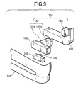
- For example, as disclosed in Japanese Patent Unexamined Publication No. Hei. 11-78732 and shown in Figs. 9 to 11, a front structure of vehicle has an upper
side bumper beam 102 and a lowerside bumper beam 103. The front face of the upperside bumper beam 102 is covered with abumper face 101 made of flexible resin. The upperside bumper beam 102 is extended in a width direction of the vehicle at a front part of a vehicle body. The upperside bumper beam 102 and the lowerside bumper beam 103 are supported by aradiator panel 106 at the front part of the vehicle body through an upper side bumper stay 104 and a lower side bumper stay 105, respectively. - The upper
side bumper stay 104 has a double structure constituted of a longouter pipe stay 107, and a short inner pipe stay 108. The longouter pipe stay 107 is secured to both of the upperside bumper beam 102 and theradiator panel 106. The shortinner pipe stay 108 is secured only to theradiator panel 106. Theouter pipe stay 107 is constituted of afront side stay 107a having a higher strength and arear side stay 107b having a lower strength. Thefront side stay 107a is expanded toward its front end side, as shown in Fig. 10. - Furthermore, the lower
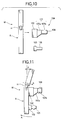
side bumper stay 105 is secured to the lowerside bumper beam 103 with its front end side, and to theradiator panel 106 with its rear end through a bracket (not illustrated) . The upperside bumper stay 104 has a strength in the longitudinal direction determined to be lower than that of the lower side bumper stay 105. - Then, when the vehicle running at a low speed has a minor collision with a pedestrian M as schematically shown in Fig. 10 illustrating a state before the collision and in Fig. 11 after the collision, for example, the upper
side bumper beam 102 abuts against a lower limb R near a knee H and the lowerside bumper beam 103 abuts against a lower part of the lower limb R. - At this time, the low strength rear side stay 107b of the upper side bumper stay 104 supporting the upper
side bumper beam 102 is compressed to be crushed and deformed, and the lower side bumper stay 105 itself is compressed to be crushed and deformed, which relieves an impact. In such a case, the upper side bumper stay 104, having the strength determined to be lower than that of the lower side bumper stay 105, is more largely deformed. This produces a force acting to turn the lower limb R of the pedestrian in directions indicated by arrows A as shown in Fig. 11, that is, in the direction of scooping up an under part of the lower limb R. Thus produced force reduces a bending angle appeared at the knee H to reduce the impact load imposed on the knee H. This appropriately controls behavior of the lower limb R at the collision to bring reduction in the load on the knee H. - In the above structure, for a large impact force, it is provided so that both of the front side stay 107a having a high strength and the inner pipe stay inside
stay 108 are compressed to be crushed and deformed. - According to the above Japanese Patent Unexamined Publication No. Hei. 11-78732, protection of a leg of a pedestrian, particularly of the knee which is susceptible to be damaged, is provided when a vehicle running particularly at a low speed has a minor collision with the pedestrian.
- In the above bumper structure, the upper side and lower side bumper stays 104 and 105 are disposed at a spot near each of the right and left ends of the vehicle. Therefore, when the pedestrian M comes into a minor collision with the upper side and lower
side bumper beams side bumper stay 105 are compressed to be crushed and deformed to exhibit required performance. However, when the pedestrian M is collided with near the central part of each of the upper side and lowerside bumper beams - In addition, there is fear that the reduced strength of the upper side bumper stay 104 accompanies reduction in rigidity for supporting the upper
side bumper beam 102 to make a sufficient bumper function unachievable when a large impact load is exerted. - Furthermore, the
lower bumper beam 103 placed in front of theradiator panel 106 necessitates conserving a space therefor to restrict design flexibility of the front part of the vehicle. Along with this, it is feared that increased number of parts leads to increases in manufacturing cost and parts stock control cost. - Accordingly, it is an object of the present invention to provide a front structure of a vehicle body which can provide the design flexibility of the front part of a vehicle and reduction in the number of parts, and along with this, can obtain a sufficient bumper function and sufficient reduction of damage of the pedestrian.
- In order to achieve the above object, the front structure of a vehicle body according to the invention, comprises a bumper and a radiator panel. The radiator panel has an upper frame and a lower frame both extendedly provided in the width direction of the vehicle at a front part of the vehicle body. The bumper is extendedly provided in a width direction of the vehicle in front of the radiator panel. The bumper comprises an upper side bumper beam extendedly provided in the width direction of the vehicle above the lower frame, an upper part bumper extendedly provided in the width direction of the vehicle and having an upper side impact absorbing material provided between the upper side bumper beam and an upper bumper face, the lower frame of the radiator panel, and a lower part bumper extendedly provided in the width direction of the vehicle and having an lower side impact absorbing material provided between the lower frame and an lower bumper face.
- In the above-mentioned structure, the lower and upper bumper faces are integrally formed as a sole bumper face unit.
- According to the invention, by forming the lower part bumper with the lower side impact absorbing material provided between the lower frame of the radiator panel and the bumper face, in providing the bumper having the upper part bumper and the lower part bumper both extendedly provided in the width direction of the vehicle at a front part of the vehicle body, the lower frame of the radiator panel is allowed to function as a bumper beam of the lower part bumper. This necessitates no space for separately providing a bumper beam of the lower part bumper to ensure the design flexibility of the front part of the vehicle. Along with this, the number of parts is reduced to allow the structure to achieve lightweight with a simplified constitution.
- Furthermore, the upper side impact absorbing material and the lower side impact absorbing material, extendedly provided along the upper side bumper beam constituting the upper part bumper and the lower frame, respectively, have approximately the same cross-sectional profile at any arbitrary position in the width direction of the vehicle . This can ensure a uniform bumper function.
- In the structure according to the present invention, it is advantageous that , the radiator panel is made inclined so that a front face of the radiator panel is faced up.
- According to the above-mentioned structure, by making the radiator panel inclined, a highly rigid structure such as a hood locking device disposed above the radiator panel can be shifted toward the rear of the vehicle body. Along with this, it becomes possible to incline the front part of the vehicle body, which can control the behavior of a lower limb of a pedestrian when the vehicle has a minor collision with the pedestrian while running at a low speed to reduce damage of the pedestrian.
- In the structure according to the present invention, it is advantageous that, the lower side impact absorbing material has a strength against a longitudinal load higher than that of the upper side impact absorbing material.
- According to the above-mentioned structure of the present invention, when a vehicle running at a low speed has a minor collision with the pedestrian, the upper part bumper butts the lower limb near a knee and the lower part bumper beam butts a lower part of the lower limb. However, the lower side impact absorbing material, having a strength against a longitudinal load higher than that of the upper side impact absorbing material, is compressed to be crushed and deformed with an amount smaller than that of the upper side impact absorbing material. This makes the lower part bumper push the lower part of the lower limb to scoop it up, and makes the upper part bumper relatively moves the lower limb near the knee backward to provide the whole lower limb a turning force to reduce an impact load on the knee. Therefore, a bending angle appeared at the knee can be made small to allow damage particularly to the knee to be reduced.
- In the structure according to the present invention, it is advantageous that, the lower part bumper is provided with a top end position of the bumper face thereof being set ahead of a top end position of the bumper face of the upper part bumper.
- According to the above-mentioned structure of the present invention, the top end of the lower part bumper is positioned ahead of the top end of the upper part bumper. Therefore, when a pedestrian has a minor collision with the bumper, the lower part bumper first butts a lower part of the lower limb, and then, the upper part bumper butts the lower limb near a knee. This can provide the lower limb a turning force to allow damage to the knee to be reduced.
- The above-mentioned object can also be achieved by, according to the present invention, a front structure of a vehicle body having a radiator panel extendedly provided in a width direction of a vehicle with a radiator mounted thereon and having structures disposed near an upper end of the radiator panel in a front end part of a hood, the radiator panel is made inclined relative to a vertical direction so that a front face of the radiator panel is faced up.
- According to the invention as described above, by making the radiator panel inclined relative to a vertical direction, a highly rigid structure such as a hood locking device disposed at the front end of a hood can be shifted toward the rear of the vehicle body. Along with this, it becomes possible to incline the front part of the vehicle body, which can control the behavior of a lower limb of a pedestrian when the vehicle running at a low speed has a minor collision with the pedestrian to reduce damage of the pedestrian.
- Note that the above-mentioned object can also be attained by a front structure of a vehicle body, according to the present invention comprising:
- a radiator panel including an upper frame and a lower frame which are extended in a width direction of the vehicle body and are located at a front part of the vehicle body in a longitudinal direction of the vehicle body;
- a bumper extended in the width direction of the vehicle
body and located in front of the radiator, the bumper including,
- an upper side bumper beam extended in the width direction of the vehicle body and located a position higher than the lower frame of the radiator in a vertical direction,
- an upper part bumper extended in the width direction of the vehicle body and having an upper bumper face and an upper side impact absorbing material provided between the upper side bumper beam and the upper bumper face, and
- a lower part bumper extended in the width direction of the vehicle body and having an lower bumper face and a lower side impact absorbingmaterial provided between the lower bumper face and the lower frame of the radiator, whereby the lower frame of the radiator operates a lower side bumper beam function.
-
- Further, the above-mentioned object can further be achieved by a front structure of a vehicle body, according to the present invention, comprising:
- a radiator panel extended in a width direction of the vehicle body and located at a front part of the vehicle body in a longitudinal direction of the vehicle body;
- a front end part of a hood of the vehicle body including a rigid component which is located in the front end part,
- wherein the radiator panel is made inclined relative to a vertical direction so that a front face of the radiator panel is faced up.
- Fig. 1 is a perspective view showing a front part of a vehicle explaining a first embodiment of a front structure of a vehicle body according to the present invention;
- Fig. 2 is a view taken in the direction of the arrows along the line I-I in Fig. 1;
- Fig. 3 is a perspective view showing a radiator panel and a bumper beam according to the first embodiment of the front structure of the vehicle body;
- Fig. 4 is a view showing vertical positional relationship between a lower limb and a bumper according to the first embodiment of the front structure of the vehicle body;
- Fig. 5 is an explanatory diagram showing an operation of the bumper in the first embodiment of the front structure of the vehicle body;
- Fig. 6 is an explanatory diagram showing the operation of the bumper in the first embodiment of the front structure of the vehicle body;
- Fig. 7 is an explanatory diagram showing an operation of a bumper in a second embodiment of the front structure of the vehicle body according to the present invention;
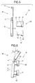
- Fig. 8 is an explanatory diagram showing the operation of the bumper in the second embodiment of the front structure of the vehicle body;
- Fig. 9 is an exploded perspective view showing a bumper in the related art;
- Fig. 10 is an explanatory diagram showing an operation of the bumper in the related art; and
- Fig. 11 is an explanatory diagram showing the operation of the bumper in the related art.
-
- A first embodiment of the front structure of a vehicle body according to the present invention will be explained below with reference to Fig. 1 to Fig. 6.
- Figure 1 is a perspective view showing a front part of a vehicle body, and Figure 2 is a view taken in the direction of arrows along line I-I in Fig. 1.
- A front structure of a
vehicle body 1 has abumper 10 and aradiator panel 40 disposed after thebumper 10. Thebumper 10 comprises anupper part bumper 20 and alower part bumper 30. - The
radiator panel 40, as shown in Fig. 3 as a perspective viewthereof, has anupper frame 41, alower frame 42, andvertical frames vertical frame 43 connects left ends of the upper andlower frames vertical frame 44 connects right ends of the upper andlower frames radiator mounting space 40a. Furthermore, center portions of theupper frame 41 and thelower frame 42 are bridged by astay 45. - At upper parts of the
vertical frames headlight mounting spaces vertical frames front ends - The
upper part bumper 20 of thebumper 10 is formed by an upperside bumper beam 21 and an upper sideimpact absorbing material 22 provided between the upperside bumper beam 21 and abumper face 23. The upperside bumper beam 21 and the upper sideimpact absorbing material 22 are extendedly provided in the width direction of the vehicle. Thelower part bumper 30 is formed by thelower frame 42 of theradiator panel 40 functioning as a lower side bumper beam and a lower sideimpact absorbing material 32 provided between thelower frame 42. Thelower frame 42 and thebumper face 23 are extending in the width direction of the vehicle. - The upper
side bumper beam 21 constituting theupper part bumper 20 is shaped to have a hollow rectangular cross section and extends in the width direction of the vehicle. As shown in Fig. 3, onto arear face 21a of each of the left and right ends of the upperside bumper beam 21, there is secured each of bumper beam stays 24 and 25 projected backward. Rear ends 24a and 25a of the bumper beam stays 24 and 25 are secured to the front ends 51a and 52a of the left and right side frames 51 and 52 connected to theradiator panel 40, respectively. - The
lower frame 42 of theradiator panel 40 forming thelower part bumper 30 is shaped to have a hollow rectangular cross section and, as a reinforcing member, is extended in the width direction of the vehicle over the approximately whole width of the vehicle and arranged below the upperside bumper beam 21 approximately in parallel therewith with an appropriate clearance therefrom. - The
bumper face 23 is an easily deformable member formed of material such as flexible resin and covers front faces of the upper sideimpact absorbing material 22 and the lower sideimpact absorbing material 32. - However, note that although in this embodiment the
bumper face 23 located in front of the upper sideimpact absorbing material 32 and thebumper face 23 located in front of the lower sideimpact absorbing material 22 are integrally formed as a single bumper face unit, it is possible to provide thebumper face 23 as separated members for respectiveimpact absorbing materials - The
lower part bumper 30 is formed to have a height in a vertical direction smaller than that of theupper part bumper 20 and is disposed below theupper part bumper 20 with anair intake 18 provided between them. - Here, the
lower part bumper 30 is constituted so that its amount of deformation is smaller than that of theupper part bumper 20 to the same load. Specifically, in a comparison between the lower sideimpact absorbing material 32 and the upper sideimpact absorbing material 22 about the strength against a longitudinal load, the strength of the lower sideimpact absorbing material 32 is determined so that it is larger than that of the upper sideimpact absorbing material 22. - For example, when forming the upper side and lower side
impact absorbing materials impact absorbing material 22 is made larger than that in the lower sideimpact absorbing material 32. Furthermore, for example, when forming the upper side and lower sideimpact absorbing materials impact absorbing material 32 is determined to be higher than that for the upper sideimpact absorbing material 22. - By thus forming the upper side and lower side
impact absorbing materials upper part bumper 20 and thelower part bumper 30 from the front, theupper part bumper 20 becomes easy to be deformed, while thelower part bumper 30 becomes hard to be deformed. - On the
radiator panel 40, as shown in Fig. 2, there are mounted aradiator 53 for cooling an engine and acondenser 54 for an air conditioner, inserted in theradiator mounting space 40a from the rear. To theradiator panel 40, a cooling fan (not illustrated) is further secured with bolts or the like so as to be positioned at the rear part of theradiator 53, and head lights (not illustrated) are mounted at the headlight mounting spaces - In this embodiment, as shown in Figs . 2 and 5, the position of the top end of the
bumper face 23 as the position of the top end of thelower part bumper 30 is substantially aligned, in a line extending in a vertical direction, with the position of the top end of thebumper face 23 as the position of the top end of theupper part bumper 20. - The
radiator panel 40, with theradiator 53, thecondenser 54, the cooling fan, and the head lights being mounted, is installed at the front of the main vehicle body in an inclined position so that the front face thereof is faced up, namely, being inclined so that the upper part of the front face is positioned further backward. - Incidentally,
reference numerals - Furthermore, the
lower frame 42 made function as a lower side bumper beam eliminates the lower side bumper beam to make it unnecessary to prepare the space for disposing the lower side bumper beam. The thus conserved space provides flexibility in designing the front part of the vehicle including thebumper 10, theradiator panel 40, and the like. - In addition, thus conserved space allows the
radiator panel 40 to incline its front face so as to be faced up. Therefore, thelower frame 42 can be disposed forward, and theupper frame 41 can be disposed backward. This makes it possible to arrange a structure with high strength such as ahood lock device 57 backward which is arranged at the front end of thehood 56 near theupper frame 41. - In the next, operation and working effects of thus constituted front structure of a vehicle body will be explained with reference to Fig. 4, and Fig. 5 and Fig. 6 both schematically showing states before and after a minor collision, respectively. In the figures, illustration of components unnecessary for the explanation will be appropriately omitted.
- When the vehicle running at a low speed has a minor collision with a pedestrian M, the
upper side bumper 20 abuts against a lower limb R near a knee H. At the same time, thelower side bumper 30 abuts against a lower part of the lower limb R. At this time, the lower sideimpact absorbing material 32, having a strength against a longitudinal load higher than that of the upper sideimpact absorbing material 22, is compressed to be crushed and deformed with an amount smaller than that of the upper sideimpact absorbing material 22. This makes thelower part bumper 30 push the lower part of the lower limb R to scoop it up, and makes theupper part bumper 20 relatively move the lower limb R near the knee H backward to provide the whole lower limb R a turning force in a directions indicated by arrows A. This reduces an impact load on the knee H to allow a bending angle appeared at the knee to be made small. - In this way, by appropriately controlling behavior of the lower limb R at the collision, damage to the lower limb R, in particular damage to the knee H, can be reduced.
- Moreover, each of the
bumper face 23 constituting theupper part bumper 20, the upper sideimpact absorbing material 22 and the upperside bumper beam 21 is extendedly provided in the width direction of the vehicle with the structure at any arbitrary position in the width direction of the vehicle being the same. Also about thelower part bumper 30, the structure at any arbitrary position in the width direction of the vehicle is the same. This, even when the pedestrian M has a minor collision with thebumper 10 at any arbitrary position in the width direction of the vehicle, can effectively relieve damage given to the knee H. - Furthermore, the lower limb R of the pedestrian M, to which a turning force is given by the
bumper 10 in the directions indicated by arrows A, contacts the vehicle with a thigh D over from thefront grille 55 to the front end of thehood 56 . However, as shown in Fig. 2, the front structure is formed to draw a smooth curve throughout from thefront grille 55 to the front end of thehood 56, and the structure with a high strength such as thehood locking device 57 is arranged so that it is retreated backward. Therefore, an impact on the thigh D at the contact can be reduced. - A second embodiment will be explained by Fig. 7 and Fig. 8.
- In the second embodiment shown in the figures, the mode differs from the above first embodiment in that strengths of the upper side and lower side
impact absorbing materials bumper face 23 as the position of the top end of thelower part bumper 30 is set ahead of the position of the top end of thebumper face 23 as the position of the top end of theupper part bumper 20. - Also in the second embodiment, like in the above first embodiment, a turning force in the direction shown by the arrows A can be provided for the lower limb R. Namely, when the pedestrian M has a minor collision with the
bumper 10, thelower part bumper 30 first abuts against the lower part of the lower limb R, and theupper part bumper 20 thereafter abuts against near the knee H. Therefore, like in the first embodiment, a turning force is provided for the lower limb R in the directions indicated by the arrows A. - This, like in the first embodiment, can appropriately control behavior of the lower limb R at the collision to reduce damage to the knee H. In addition, the
upper part bumper 20 and thelower part bumper 30, each having the same structure at any arbitrary position in the width direction of the vehicle, can relieve damage given to the knee H even when the pedestrian M has a minor collision with thebumper 10 at any arbitrary position in the width direction of the vehicle. - It is to be understood that the present invention is not limited to the above modes and can be variously modified without departing from the spirit and scope of the invention. For example, explanations were made, in the first embodiment, about the case in which the strengths of the upper side and lower side
impact absorbing materials upper part bumper 20 is different from that of thelower part bumper 30. However these modes can be appropriately combined. Specifically, even with a strength difference between the upper side and lower sideimpact absorbing materials upper part bumper 20 and thelower part bumper 30 set smaller, a turning force can be provided for the lower limb R of the pedestrian M to make it possible to assure a similar effect to that in the second embodiment. - Moreover, in each of the above modes, an explanation was made about the case in which the
bumper 10 has theupper part bumper 20 and thelower part bumper 30. However, to position theradiator panel 40 made inclined so that the front face thereof is faced up can be also applied to a bumper without thelower part bumper 30. In this case, equivalent operation and working-effect can be also ensured. Namely, a structure with a high strength such as a hood locking 57 that can be disposed in being retreated makes it possible to ensure the operation and working effect of reducing damage on the lower limb R, particularly on the thigh D, of the pedestrian M. - By the above-explained front structure of a vehicle body according to the present invention, the lower frame of the radiator panel is made to function as a bumper beam. This necessitates no space for disposing the lower side bumper beam to expand flexibility in designing the front part of the vehicle body.
- In addition, the radiator panel inclined with the front face being faced up makes the upper frame retreated from the lower frame. Therefore, a structure with a high strength and/or rigidity such as the hood locking device disposed near the upper frame can be arranged backward by an amount by which the upper frame is retreated. This can determine the shape of the top end of the vehicle body as a shape that can well control the behavior of the lower limb of the pedestrian when the vehicle running at a low speed has a minor collision with the pedestrian, and can further prevent the lower limb from being butted by the structure with a high strength such as the locking device. That is, it becomes possible to reduce damage on the lower limb of the pedestrian.
- While the presently preferred embodiment of the present invention has been shown and described, it is to be understood that this disclosure is for the purpose of illustration and that various changes and modifications may be made without departing from the scope of the invention as set forth in the appended claims.
Claims (7)
- A front structure of a vehicle body comprising:a radiator panel including an upper frame and a lower frame which are extended in a width direction of said vehicle body and are located at a front part of the vehicle body in a longitudinal direction of said vehicle body;a bumper extended in the width direction of the vehicle body and located in front of said radiator, said bumper including,an upper side bumper beam extended in the width direction of the vehicle body and located a position higher than the lower frame of said radiator in a vertical direction,an upper part bumper extended in the width direction of the vehicle body and having an upper bumper face and an upper side impact absorbing material provided between said upper side bumper beam and said upper bumper face, anda lower part bumper extended in the width direction of the vehicle body and having an lower bumper face and a lower side impact absorbing material provided between said lower bumper face and said lower frame of said radiator, whereby said lower frame of said radiator operates a lower side bumper beam function.
- The front structure according to claim 1, wherein said upper and lower bumper faces are integrally formed as a single unit.
- The front structure according to claim 1 or 2, wherein end positions of the lower and upper bumper faces in the longitudinal direction of the vehicle body are substantially aligned with each other in a line extending in the vertical direction.
- The front structure according to claim 1, 2 or 3, wherein said radiator panel is inclined relative to the vertical direction so that a front face of the radiator panel is faced up.
- The front structure according to claim 1, 2, 3 or 4, wherein said lower side impact absorbing material has a strength against a longitudinal load higher than that of said upper side impact absorbing material.
- The front structure according to any one of claims 1, 2, 4 or 5, wherein an end position of the lower bumper face thereof is set ahead of an end position of the upper bumper face in the longitudinal direction.
- A front structure of a vehicle body comprising:a radiator panel extended in a width direction of said vehicle body and located at a front part of the vehicle body in a longitudinal direction of said vehicle body;a front end part of a hood of said vehicle body including a rigid component which is located in said front end part,wherein said radiator panel is made inclined relative to a vertical direction so that a front face of the radiator panel is faced up.
Applications Claiming Priority (2)
| Application Number | Priority Date | Filing Date | Title |
|---|---|---|---|
| JP2000092795 | 2000-03-30 | ||
| JP2000092795A JP4605849B2 (en) | 2000-03-30 | 2000-03-30 | Body front structure |
Publications (3)
| Publication Number | Publication Date |
|---|---|
| EP1138557A2 true EP1138557A2 (en) | 2001-10-04 |
| EP1138557A3 EP1138557A3 (en) | 2002-04-03 |
| EP1138557B1 EP1138557B1 (en) | 2004-06-09 |
Family
ID=18608068
Family Applications (1)
| Application Number | Title | Priority Date | Filing Date |
|---|---|---|---|
| EP01107721A Expired - Lifetime EP1138557B1 (en) | 2000-03-30 | 2001-03-30 | Front structure of vehicle body securing safety of pedestrians |
Country Status (4)
| Country | Link |
|---|---|
| US (1) | US6676179B2 (en) |
| EP (1) | EP1138557B1 (en) |
| JP (1) | JP4605849B2 (en) |
| DE (1) | DE60103687T2 (en) |
Cited By (14)
| Publication number | Priority date | Publication date | Assignee | Title |
|---|---|---|---|---|
| WO2003039915A1 (en) * | 2001-11-03 | 2003-05-15 | Adam Opel Ag | Front structure of a motor vehicle |
| GB2394920A (en) * | 2002-11-07 | 2004-05-12 | Ford Global Tech Inc | Extendible safety device above a vehicle bumper |
| FR2848946A1 (en) * | 2002-12-19 | 2004-06-25 | Valeo Thermique Moteur Sa | Pedestrian protecting device for automobile, has detector placed below bonnet of engine and pushed down, when bonnet is deformed, and locking mechanism maintaining heat exchanger in proximity to bonnet |
| EP1384629A3 (en) * | 2002-07-25 | 2004-10-20 | Fuji Jukogyo Kabushiki Kaisha | Bumper structure for vehicle |
| EP1433664A3 (en) * | 2002-12-25 | 2005-06-08 | Mazda Motor Corporation | Automobile bumper structure |
| WO2005056344A3 (en) * | 2003-12-09 | 2005-08-25 | Decoma Germany Gmbh | Structural member of a vehicle fender assembly |
| EP1398199A3 (en) * | 2002-09-09 | 2006-06-21 | Fuji Jukogyo Kabushiki Kaisha | Heat exchanger mounting structure for vehicle |
| US7086690B2 (en) | 2004-08-24 | 2006-08-08 | General Electric Company | Bumper assembly including twin energy absorbers |
| EP1698520A1 (en) | 2005-03-03 | 2006-09-06 | HBPO GmbH | Frontbody structure with pedestrian protection device |
| EP1813485A1 (en) * | 2006-01-31 | 2007-08-01 | Mazda Motor Corporation | Front structure of an automotive vehicle |
| US7296833B2 (en) | 2005-09-27 | 2007-11-20 | Sabic Innovative Plastics Ip Bv | Bumper system with integrated energy absorber underbar |
| EP1884416A1 (en) * | 2006-08-01 | 2008-02-06 | Peugeot Citroën Automobiles S.A. | Frame for the front block of an automobile vehicle. |
| FR2908717A1 (en) * | 2006-11-20 | 2008-05-23 | Renault Sas | AUTOMOTIVE VEHICLE ARRANGEMENT FOR THE PROTECTION OF PIETONS IN CASES OF FRONTAL SHOCK |
| DE102008025132B4 (en) * | 2007-05-29 | 2015-08-06 | GM Global Technology Operations LLC (n. d. Ges. d. Staates Delaware) | Rotatable attachable bumper and method for cushioning the contact between an engine hood and a radiator grille of a vehicle |
Families Citing this family (57)
| Publication number | Priority date | Publication date | Assignee | Title |
|---|---|---|---|---|
| JP2002274430A (en) * | 2001-03-15 | 2002-09-25 | Fuji Heavy Ind Ltd | Body front structure |
| FR2830229B1 (en) * | 2001-09-28 | 2004-01-23 | Valeo Equip Electr Moteur | FRONT PANEL OF MOTOR VEHICLE INCLUDING A BUMPER BEAM |
| DE10248440B4 (en) * | 2002-10-17 | 2008-09-18 | Daimler Ag | Air duct in the stem of a motor vehicle |
| ITMI20031411A1 (en) * | 2003-07-10 | 2005-01-11 | Adlev Srl | PROTECTIVE STRUCTURE FOR VEHICLES, SUITABLE FOR USE IN PARTICULAR IN THE EVENT OF IMPACT WITH PEDONS |
| KR100535759B1 (en) * | 2003-10-17 | 2005-12-12 | 현대모비스 주식회사 | Structure for reinforcement in front end module carrier |
| KR20050048376A (en) * | 2003-11-19 | 2005-05-24 | 현대모비스 주식회사 | Carrier mounting structure |
| DE102004030794B4 (en) * | 2004-06-25 | 2009-05-07 | Hbpo Gmbh | Vehicle front end module with pedestrian protection device |
| JP2006036082A (en) * | 2004-07-28 | 2006-02-09 | Honda Motor Co Ltd | Bumper structure for vehicles |
| FR2875771B1 (en) * | 2004-09-30 | 2020-02-07 | Valeo Thermique Moteur | IMPACT PROTECTION DEVICE FOR A FRONT PANEL OF A MOTOR VEHICLE AND FRONT PANEL COMPRISING THE DEVICE |
| DE102004057214A1 (en) * | 2004-11-26 | 2006-06-01 | Audi Ag | Trim panel`s front end region for motor vehicle, has bumper cover provided on front side of trim panel, and absorber unit assigned on rear side of bumper cover, where absorber unit is provided on lower region of bumper cover |
| DE102005002068A1 (en) * | 2005-01-14 | 2006-08-03 | Behr Gmbh & Co. Kg | Fastening device for a heat exchanger unit and vehicle with a heat exchanger unit |
| DE102005017567A1 (en) * | 2005-04-16 | 2006-10-19 | Daimlerchrysler Ag | motor vehicle front |
| DE102005026868A1 (en) * | 2005-06-10 | 2006-12-14 | GM Global Technology Operations, Inc., Detroit | Pedestrian protection for off-road vehicles by Upper Support Structure |
| DE102005044288A1 (en) * | 2005-09-16 | 2007-04-05 | GM Global Technology Operations, Inc., Detroit | Cooling system for a motor vehicle |
| DE102005059447A1 (en) * | 2005-12-13 | 2007-06-14 | GM Global Technology Operations, Inc., Detroit | Bumper system for a motor vehicle |
| JP4802736B2 (en) * | 2006-01-31 | 2011-10-26 | マツダ株式会社 | Automotive front structure |
| JP4725365B2 (en) * | 2006-03-01 | 2011-07-13 | 日産自動車株式会社 | Engaging and fixing structure and engaging and fixing method |
| US7703566B2 (en) * | 2006-05-19 | 2010-04-27 | Gm Global Technology Operations, Inc. | Integrated automotive tie bar and upper condenser, radiator and fan module brackets |
| DE102006036852B4 (en) * | 2006-08-07 | 2018-11-08 | GM Global Technology Operations LLC (n. d. Ges. d. Staates Delaware) | Front end for a motor vehicle |
| DE202006020846U1 (en) * | 2006-09-01 | 2010-07-22 | Audi Ag | Impact protection element for a vehicle and body with such an impact protection element |
| KR101373546B1 (en) | 2007-01-12 | 2014-03-12 | 한라비스테온공조 주식회사 | Automotive Front End Modules |
| EP2033855B1 (en) * | 2007-09-10 | 2010-07-28 | Ford Global Technologies, LLC | Pedestrian Safety Structure for a Motor Vehicle Body |
| JP5109569B2 (en) * | 2007-10-15 | 2012-12-26 | トヨタ車体株式会社 | Front bumper structure |
| US8042847B2 (en) * | 2007-12-19 | 2011-10-25 | Sabic Innovative Plastics Ip B.V. | Tray energy absorber and bumper system |
| DE102008024121B4 (en) * | 2008-05-17 | 2018-06-28 | Dr. Ing. H.C. F. Porsche Aktiengesellschaft | Motor vehicle with a pedestrian protection system |
| DE102008039972A1 (en) * | 2008-08-27 | 2010-03-04 | Dr.Ing.H.C.F.Porsche Aktiengesellschaft | Front structure of a motor vehicle |
| DE102009058287A1 (en) * | 2009-12-14 | 2011-06-16 | GM Global Technology Operations LLC, ( n. d. Ges. d. Staates Delaware ), Detroit | Front structure for motor vehicle, has structural elements provided such that upper transverse carrier and lower transverse carrier are interconnected, and bumper transverse carrier arranged between upper and lower transverse carriers |
| JP5440207B2 (en) * | 2010-01-22 | 2014-03-12 | スズキ株式会社 | Body front structure |
| US8770637B2 (en) * | 2010-07-08 | 2014-07-08 | Basf Se | Module for absorbing energy |
| US8336933B2 (en) | 2010-11-04 | 2012-12-25 | Sabic Innovative Plastics Ip B.V. | Energy absorbing device and methods of making and using the same |
| US8322780B2 (en) | 2010-12-20 | 2012-12-04 | Sabic Innovative Plastics Ip B.V. | Reinforced body in white and method of making and using the same |
| JP5433652B2 (en) * | 2011-08-24 | 2014-03-05 | 富士重工業株式会社 | Vehicle front structure |
| JP5839890B2 (en) * | 2011-08-29 | 2016-01-06 | ダイハツ工業株式会社 | Front end structure of the vehicle |
| DE102011119542B4 (en) | 2011-11-26 | 2026-04-23 | Volkswagen Aktiengesellschaft | Front end module for a motor vehicle |
| US8763738B2 (en) * | 2012-02-06 | 2014-07-01 | Honda Motor Co., Ltd. | Front end structure for vehicle |
| US9714602B2 (en) * | 2012-03-16 | 2017-07-25 | Honda Motor Co., Ltd. | Airflow directing member for a vehicle engine compartment |
| US20130248141A1 (en) * | 2012-03-26 | 2013-09-26 | Honda Motor Co., Ltd. | Ducting arrangement and method for directing airflow toward a radiator |
| CN103832387A (en) * | 2012-11-27 | 2014-06-04 | 上海汽车集团股份有限公司 | Pedestrian leg protecting system and vehicle |
| US8864216B2 (en) | 2013-01-18 | 2014-10-21 | Sabic Global Technologies B.V. | Reinforced body in white and method of making and using the same |
| US9067550B2 (en) | 2013-01-18 | 2015-06-30 | Sabic Global Technologies B.V. | Polymer, energy absorber rail extension, methods of making and vehicles using the same |
| DE102013111615A1 (en) * | 2013-10-22 | 2015-04-23 | Dr. Ing. H.C. F. Porsche Aktiengesellschaft | Bug module of a motor vehicle |
| JP6178697B2 (en) * | 2013-11-05 | 2017-08-09 | 株式会社Subaru | Shock absorbing member |
| JP6131837B2 (en) * | 2013-11-15 | 2017-05-24 | マツダ株式会社 | Vehicle front structure |
| US9205803B2 (en) | 2014-01-03 | 2015-12-08 | Ford Global Technologies, Llc | Deployable upper leg stiffener for pedestrian protection |
| EP3513958B1 (en) | 2014-06-16 | 2024-09-25 | SABIC Global Technologies B.V. | Method of making a laminate |
| US9969342B2 (en) * | 2015-03-26 | 2018-05-15 | Ford Global Technologies Llc | Body-on-frame bumper step pad with seal between bumper beam and radiator grill |
| USD820749S1 (en) | 2015-12-29 | 2018-06-19 | Sabic Global Technologies B.V. | Roof component for a motor vehicle |
| CN105730385B (en) * | 2016-03-14 | 2019-01-01 | 奇瑞汽车股份有限公司 | rear bumper mounting structure |
| CN106114441A (en) * | 2016-06-22 | 2016-11-16 | 浙江吉利控股集团有限公司 | Vehicle front bumper mounting structure, vehicle front bumper assembly and vehicle |
| JP6443469B2 (en) * | 2017-02-17 | 2018-12-26 | マツダ株式会社 | Vehicle front structure |
| JP2020083117A (en) | 2018-11-27 | 2020-06-04 | トヨタ自動車株式会社 | Vehicle front structure |
| USD951157S1 (en) * | 2020-01-30 | 2022-05-10 | Kia Motors Corporation | Front bumper cover for automobile |
| USD945937S1 (en) * | 2020-03-05 | 2022-03-15 | Kia Motors Corporation | Front bumper for an automobile |
| USD955942S1 (en) * | 2020-03-31 | 2022-06-28 | Kia Motors Corporation | Front bumper cover for automobile |
| USD949065S1 (en) * | 2020-07-10 | 2022-04-19 | Hyundai Motor Company | Front bumper cover for vehicles |
| USD949758S1 (en) * | 2020-11-19 | 2022-04-26 | Hyundai Motor Company | Front bumper cover for vehicles |
| CN116607850A (en) * | 2023-05-30 | 2023-08-18 | 阿维塔科技(重庆)有限公司 | Front shroud lock system and vehicle |
Citations (1)
| Publication number | Priority date | Publication date | Assignee | Title |
|---|---|---|---|---|
| JPH1178732A (en) | 1997-09-01 | 1999-03-23 | Nissan Motor Co Ltd | Automotive bumper structure |
Family Cites Families (25)
| Publication number | Priority date | Publication date | Assignee | Title |
|---|---|---|---|---|
| US2062315A (en) | 1934-06-11 | 1936-12-01 | Gen Spring Bumper Corp | Vehicle bumper construction |
| DE2229782A1 (en) * | 1972-06-19 | 1974-01-10 | Volkswagenwerk Ag | VEHICLE, IN PARTICULAR MOTOR VEHICLE, WITH A BODY END AREA MADE OF RUBBER OR PLASTIC |
| IT986580B (en) * | 1973-06-25 | 1975-01-30 | Fiat Spa | BUMPERS OF ELASTIC MATERIAL FOR MOTOR VEHICLES |
| US3869167A (en) * | 1973-10-01 | 1975-03-04 | Ford Motor Co | Resilient bumper assembly |
| FR2445783A1 (en) * | 1979-01-03 | 1980-08-01 | Peugeot | Shock absorbing assembly for front of car - has three deformable parts at varying heights intended to protect pedestrian if hit |
| US4348042A (en) * | 1980-07-14 | 1982-09-07 | Ex-Cell-O Corporation | Vehicle bumper assembly |
| DE3338466C2 (en) * | 1983-10-22 | 1987-01-02 | Dr.Ing.H.C. F. Porsche Ag, 7000 Stuttgart | Cooling air duct for a motor vehicle, in particular for a passenger car |
| JPH01168544A (en) * | 1987-12-23 | 1989-07-04 | Suzuki Motor Co Ltd | Bumper for automobile |
| JP2605891B2 (en) * | 1989-10-20 | 1997-04-30 | 日産自動車株式会社 | Mounting structure of bumper fascia |
| JPH05112196A (en) * | 1991-06-25 | 1993-05-07 | Mazda Motor Corp | Structure for fitting air bag sensor for automobile |
| JP2596056Y2 (en) * | 1993-01-25 | 1999-06-07 | 富士重工業株式会社 | Module carrier structure at the front end of the vehicle |
| DE4437083C2 (en) | 1993-10-25 | 1996-10-17 | Fuji Heavy Ind Ltd | Module support structure |
| JP4106737B2 (en) * | 1998-04-22 | 2008-06-25 | マツダ株式会社 | Front body structure of automobile |
| DE19852959C2 (en) * | 1998-11-17 | 2002-09-12 | Daimler Chrysler Ag | Arrangement of a front guard on a motor vehicle front |
| JP3085945B1 (en) * | 1999-02-24 | 2000-09-11 | 本田技研工業株式会社 | Vehicle radiator mounting structure |
| DE19911833C2 (en) * | 1999-03-17 | 2003-12-18 | Audi Ag | Front end area for a motor vehicle |
| EP1046546B1 (en) * | 1999-04-24 | 2002-11-27 | Ford Global Technologies, Inc., A subsidiary of Ford Motor Company | Bumper for vehicles having optimal mechanical properties to improve pedestrian protection |
| US6155335A (en) * | 1999-04-26 | 2000-12-05 | Delphi Technologies, Inc. | Vehicle fan shroud and component cooling module |
| EP1065108B1 (en) * | 1999-06-28 | 2004-04-21 | Mazda Motor Corporation | Structure of the front of a vehicle body |
| JP3705049B2 (en) * | 1999-11-18 | 2005-10-12 | マツダ株式会社 | Front body structure of the vehicle |
| JP3526424B2 (en) * | 1999-11-30 | 2004-05-17 | 本田技研工業株式会社 | Radiator mounting structure |
| JP2001277963A (en) * | 2000-03-30 | 2001-10-10 | Fuji Heavy Ind Ltd | Automotive bumper structure |
| US6622808B2 (en) * | 2000-04-10 | 2003-09-23 | Denso Corporation | Resin molding for vehicle use and manufacturing method thereof |
| JP2002274430A (en) * | 2001-03-15 | 2002-09-25 | Fuji Heavy Ind Ltd | Body front structure |
| JP4762444B2 (en) * | 2001-06-15 | 2011-08-31 | 富士重工業株式会社 | Vehicle front-end structure |
-
2000
- 2000-03-30 JP JP2000092795A patent/JP4605849B2/en not_active Expired - Fee Related
-
2001
- 2001-03-28 US US09/819,016 patent/US6676179B2/en not_active Expired - Lifetime
- 2001-03-30 EP EP01107721A patent/EP1138557B1/en not_active Expired - Lifetime
- 2001-03-30 DE DE60103687T patent/DE60103687T2/en not_active Expired - Lifetime
Patent Citations (1)
| Publication number | Priority date | Publication date | Assignee | Title |
|---|---|---|---|---|
| JPH1178732A (en) | 1997-09-01 | 1999-03-23 | Nissan Motor Co Ltd | Automotive bumper structure |
Cited By (24)
| Publication number | Priority date | Publication date | Assignee | Title |
|---|---|---|---|---|
| DE10154113A1 (en) * | 2001-11-03 | 2003-05-15 | Opel Adam Ag | Front structure of a motor vehicle |
| WO2003039915A1 (en) * | 2001-11-03 | 2003-05-15 | Adam Opel Ag | Front structure of a motor vehicle |
| AU2002358415B2 (en) * | 2001-11-03 | 2008-04-03 | Adam Opel Gmbh | Front structure of a motor vehicle |
| EP1384629A3 (en) * | 2002-07-25 | 2004-10-20 | Fuji Jukogyo Kabushiki Kaisha | Bumper structure for vehicle |
| EP1398199A3 (en) * | 2002-09-09 | 2006-06-21 | Fuji Jukogyo Kabushiki Kaisha | Heat exchanger mounting structure for vehicle |
| GB2394920B (en) * | 2002-11-07 | 2005-09-21 | Ford Global Tech Inc | Motor vehicle having a front end safety device |
| GB2394920A (en) * | 2002-11-07 | 2004-05-12 | Ford Global Tech Inc | Extendible safety device above a vehicle bumper |
| FR2848946A1 (en) * | 2002-12-19 | 2004-06-25 | Valeo Thermique Moteur Sa | Pedestrian protecting device for automobile, has detector placed below bonnet of engine and pushed down, when bonnet is deformed, and locking mechanism maintaining heat exchanger in proximity to bonnet |
| WO2004056620A1 (en) * | 2002-12-19 | 2004-07-08 | Valeo Thermique Moteur | Device for protecting pedestrians in a collision with a vehicle |
| EP1433664A3 (en) * | 2002-12-25 | 2005-06-08 | Mazda Motor Corporation | Automobile bumper structure |
| CN100337857C (en) * | 2002-12-25 | 2007-09-19 | 马自达汽车株式会社 | Automobile bumper structure |
| WO2005056344A3 (en) * | 2003-12-09 | 2005-08-25 | Decoma Germany Gmbh | Structural member of a vehicle fender assembly |
| US7325861B2 (en) | 2003-12-09 | 2008-02-05 | Decoma (Germany) Gmbh | Structural component of a motor vehicle bumper arrangement |
| US7086690B2 (en) | 2004-08-24 | 2006-08-08 | General Electric Company | Bumper assembly including twin energy absorbers |
| DE102005009768A1 (en) * | 2005-03-03 | 2006-09-07 | Hbpo Gmbh | Body front structure with pedestrian protection device |
| EP1698520A1 (en) | 2005-03-03 | 2006-09-06 | HBPO GmbH | Frontbody structure with pedestrian protection device |
| US7296833B2 (en) | 2005-09-27 | 2007-11-20 | Sabic Innovative Plastics Ip Bv | Bumper system with integrated energy absorber underbar |
| EP1813485A1 (en) * | 2006-01-31 | 2007-08-01 | Mazda Motor Corporation | Front structure of an automotive vehicle |
| US7517006B2 (en) | 2006-01-31 | 2009-04-14 | Mazda Motor Corporation | Front structure of automotive vehicle |
| EP1884416A1 (en) * | 2006-08-01 | 2008-02-06 | Peugeot Citroën Automobiles S.A. | Frame for the front block of an automobile vehicle. |
| FR2904589A1 (en) * | 2006-08-01 | 2008-02-08 | Peugeot Citroen Automobiles Sa | FRAME FOR FRONT BLOCK OF MOTOR VEHICLE |
| FR2908717A1 (en) * | 2006-11-20 | 2008-05-23 | Renault Sas | AUTOMOTIVE VEHICLE ARRANGEMENT FOR THE PROTECTION OF PIETONS IN CASES OF FRONTAL SHOCK |
| WO2008062128A1 (en) * | 2006-11-20 | 2008-05-29 | Renault S.A.S. | Automotive vehicle equipment for protecting pedestrians in case of frontal collision |
| DE102008025132B4 (en) * | 2007-05-29 | 2015-08-06 | GM Global Technology Operations LLC (n. d. Ges. d. Staates Delaware) | Rotatable attachable bumper and method for cushioning the contact between an engine hood and a radiator grille of a vehicle |
Also Published As
| Publication number | Publication date |
|---|---|
| US20010026072A1 (en) | 2001-10-04 |
| DE60103687T2 (en) | 2004-10-14 |
| JP4605849B2 (en) | 2011-01-05 |
| DE60103687D1 (en) | 2004-07-15 |
| US6676179B2 (en) | 2004-01-13 |
| JP2001277964A (en) | 2001-10-10 |
| EP1138557A3 (en) | 2002-04-03 |
| EP1138557B1 (en) | 2004-06-09 |
Similar Documents
| Publication | Publication Date | Title |
|---|---|---|
| EP1138557B1 (en) | Front structure of vehicle body securing safety of pedestrians | |
| EP1300293B1 (en) | Motor vehicle with bumper assembly for pedestrian protection | |
| US6428065B2 (en) | Bumper structure for automobile | |
| CN1330516C (en) | Front structure of a motor vehicle | |
| US6224120B1 (en) | Arrangement of a front protection bow on a motor vehicle front end | |
| US6056337A (en) | Impact energy absorption structure for motor vehicle | |
| JP3705049B2 (en) | Front body structure of the vehicle | |
| JP2006175988A (en) | Body front structure | |
| JP2007246044A (en) | Automotive front structure | |
| JPH11255049A (en) | Bumper structure | |
| JP4000951B2 (en) | Auto body front structure | |
| US6941874B2 (en) | System for preventing the intrusion of a window into a rail vehicle cab in the event of an impact | |
| JP2005297726A (en) | Automotive bumper | |
| US20040160071A1 (en) | Bumper structure for vehicle | |
| JP2008536743A (en) | Car front | |
| JP2000318551A (en) | Bumper for vehicle having mechanical characteristic optimized to improve pedestrian protective performance | |
| EP2263919B1 (en) | Automobile front body structure | |
| JP4483826B2 (en) | Bumper mounting structure | |
| JP4539320B2 (en) | Mounting structure of tow hook for vehicle | |
| JP4389539B2 (en) | Cowl structure | |
| KR20060055530A (en) | Utility Car Cab | |
| JP2014184811A (en) | Vehicle front part structure | |
| KR100299620B1 (en) | Front end structure of the car | |
| KR100315060B1 (en) | Front end structure of vehicle | |
| KR100190392B1 (en) | Stable rigid steel structure for vehicle bumpers |
Legal Events
| Date | Code | Title | Description |
|---|---|---|---|
| PUAI | Public reference made under article 153(3) epc to a published international application that has entered the european phase |
Free format text: ORIGINAL CODE: 0009012 |
|
| AK | Designated contracting states |
Kind code of ref document: A2 Designated state(s): DE GB Kind code of ref document: A2 Designated state(s): AT BE CH CY DE DK ES FI FR GB GR IE IT LI LU MC NL PT SE TR |
|
| AX | Request for extension of the european patent |
Free format text: AL;LT;LV;MK;RO;SI |
|
| PUAL | Search report despatched |
Free format text: ORIGINAL CODE: 0009013 |
|
| AK | Designated contracting states |
Kind code of ref document: A3 Designated state(s): AT BE CH CY DE DK ES FI FR GB GR IE IT LI LU MC NL PT SE TR |
|
| AX | Request for extension of the european patent |
Free format text: AL;LT;LV;MK;RO;SI |
|
| RIC1 | Information provided on ipc code assigned before grant |
Free format text: 7B 60R 19/12 A, 7B 60R 21/34 B, 7B 62D 25/08 B, 7B 60K 11/04 B |
|
| 17P | Request for examination filed |
Effective date: 20020610 |
|
| 17Q | First examination report despatched |
Effective date: 20020919 |
|
| AKX | Designation fees paid |
Free format text: DE GB |
|
| GRAP | Despatch of communication of intention to grant a patent |
Free format text: ORIGINAL CODE: EPIDOSNIGR1 |
|
| GRAS | Grant fee paid |
Free format text: ORIGINAL CODE: EPIDOSNIGR3 |
|
| GRAA | (expected) grant |
Free format text: ORIGINAL CODE: 0009210 |
|
| AK | Designated contracting states |
Kind code of ref document: B1 Designated state(s): DE GB |
|
| REG | Reference to a national code |
Ref country code: GB Ref legal event code: FG4D |
|
| REF | Corresponds to: |
Ref document number: 60103687 Country of ref document: DE Date of ref document: 20040715 Kind code of ref document: P |
|
| REG | Reference to a national code |
Ref country code: IE Ref legal event code: FG4D |
|
| PGFP | Annual fee paid to national office [announced via postgrant information from national office to epo] |
Ref country code: GB Payment date: 20050330 Year of fee payment: 5 |
|
| PLBE | No opposition filed within time limit |
Free format text: ORIGINAL CODE: 0009261 |
|
| STAA | Information on the status of an ep patent application or granted ep patent |
Free format text: STATUS: NO OPPOSITION FILED WITHIN TIME LIMIT |
|
| 26N | No opposition filed |
Effective date: 20050310 |
|
| PG25 | Lapsed in a contracting state [announced via postgrant information from national office to epo] |
Ref country code: GB Free format text: LAPSE BECAUSE OF NON-PAYMENT OF DUE FEES Effective date: 20060330 |
|
| GBPC | Gb: european patent ceased through non-payment of renewal fee |
Effective date: 20060330 |
|
| PGFP | Annual fee paid to national office [announced via postgrant information from national office to epo] |
Ref country code: DE Payment date: 20170321 Year of fee payment: 17 |
|
| REG | Reference to a national code |
Ref country code: DE Ref legal event code: R082 Ref document number: 60103687 Country of ref document: DE Representative=s name: VOSSIUS & PARTNER PATENTANWAELTE RECHTSANWAELT, DE Ref country code: DE Ref legal event code: R081 Ref document number: 60103687 Country of ref document: DE Owner name: SUBARU CORPORATION, JP Free format text: FORMER OWNER: FUJI JUKOGYO K.K., TOKIO/TOKYO, JP |
|
| REG | Reference to a national code |
Ref country code: DE Ref legal event code: R119 Ref document number: 60103687 Country of ref document: DE |
|
| PG25 | Lapsed in a contracting state [announced via postgrant information from national office to epo] |
Ref country code: DE Free format text: LAPSE BECAUSE OF NON-PAYMENT OF DUE FEES Effective date: 20181002 |