EP1138550A2 - Vehicle front lamp light distribution control system - Google Patents
Vehicle front lamp light distribution control system Download PDFInfo
- Publication number
- EP1138550A2 EP1138550A2 EP01107948A EP01107948A EP1138550A2 EP 1138550 A2 EP1138550 A2 EP 1138550A2 EP 01107948 A EP01107948 A EP 01107948A EP 01107948 A EP01107948 A EP 01107948A EP 1138550 A2 EP1138550 A2 EP 1138550A2
- Authority
- EP
- European Patent Office
- Prior art keywords
- light distribution
- steering
- blinker
- steering wheel
- angle
- Prior art date
- Legal status (The legal status is an assumption and is not a legal conclusion. Google has not performed a legal analysis and makes no representation as to the accuracy of the status listed.)
- Granted
Links
Images


Classifications
-
- B—PERFORMING OPERATIONS; TRANSPORTING
- B60—VEHICLES IN GENERAL
- B60Q—ARRANGEMENT OF SIGNALLING OR LIGHTING DEVICES, THE MOUNTING OR SUPPORTING THEREOF OR CIRCUITS THEREFOR, FOR VEHICLES IN GENERAL
- B60Q1/00—Arrangement of optical signalling or lighting devices, the mounting or supporting thereof or circuits therefor
- B60Q1/02—Arrangement of optical signalling or lighting devices, the mounting or supporting thereof or circuits therefor the devices being primarily intended to illuminate the way ahead or to illuminate other areas of way or environments
- B60Q1/04—Arrangement of optical signalling or lighting devices, the mounting or supporting thereof or circuits therefor the devices being primarily intended to illuminate the way ahead or to illuminate other areas of way or environments the devices being headlights
- B60Q1/06—Arrangement of optical signalling or lighting devices, the mounting or supporting thereof or circuits therefor the devices being primarily intended to illuminate the way ahead or to illuminate other areas of way or environments the devices being headlights adjustable, e.g. remotely-controlled from inside vehicle
- B60Q1/08—Arrangement of optical signalling or lighting devices, the mounting or supporting thereof or circuits therefor the devices being primarily intended to illuminate the way ahead or to illuminate other areas of way or environments the devices being headlights adjustable, e.g. remotely-controlled from inside vehicle automatically
- B60Q1/12—Arrangement of optical signalling or lighting devices, the mounting or supporting thereof or circuits therefor the devices being primarily intended to illuminate the way ahead or to illuminate other areas of way or environments the devices being headlights adjustable, e.g. remotely-controlled from inside vehicle automatically due to steering position
-
- B—PERFORMING OPERATIONS; TRANSPORTING
- B60—VEHICLES IN GENERAL
- B60Q—ARRANGEMENT OF SIGNALLING OR LIGHTING DEVICES, THE MOUNTING OR SUPPORTING THEREOF OR CIRCUITS THEREFOR, FOR VEHICLES IN GENERAL
- B60Q2300/00—Indexing codes for automatically adjustable headlamps or automatically dimmable headlamps
- B60Q2300/10—Indexing codes relating to particular vehicle conditions
- B60Q2300/11—Linear movements of the vehicle
- B60Q2300/112—Vehicle speed
-
- B—PERFORMING OPERATIONS; TRANSPORTING
- B60—VEHICLES IN GENERAL
- B60Q—ARRANGEMENT OF SIGNALLING OR LIGHTING DEVICES, THE MOUNTING OR SUPPORTING THEREOF OR CIRCUITS THEREFOR, FOR VEHICLES IN GENERAL
- B60Q2300/00—Indexing codes for automatically adjustable headlamps or automatically dimmable headlamps
- B60Q2300/10—Indexing codes relating to particular vehicle conditions
- B60Q2300/12—Steering parameters
- B60Q2300/122—Steering angle
-
- B—PERFORMING OPERATIONS; TRANSPORTING
- B60—VEHICLES IN GENERAL
- B60Q—ARRANGEMENT OF SIGNALLING OR LIGHTING DEVICES, THE MOUNTING OR SUPPORTING THEREOF OR CIRCUITS THEREFOR, FOR VEHICLES IN GENERAL
- B60Q2300/00—Indexing codes for automatically adjustable headlamps or automatically dimmable headlamps
- B60Q2300/10—Indexing codes relating to particular vehicle conditions
- B60Q2300/12—Steering parameters
- B60Q2300/124—Steering speed
-
- B—PERFORMING OPERATIONS; TRANSPORTING
- B60—VEHICLES IN GENERAL
- B60Q—ARRANGEMENT OF SIGNALLING OR LIGHTING DEVICES, THE MOUNTING OR SUPPORTING THEREOF OR CIRCUITS THEREFOR, FOR VEHICLES IN GENERAL
- B60Q2300/00—Indexing codes for automatically adjustable headlamps or automatically dimmable headlamps
- B60Q2300/10—Indexing codes relating to particular vehicle conditions
- B60Q2300/14—Other vehicle conditions
- B60Q2300/142—Turn signal actuation
-
- F—MECHANICAL ENGINEERING; LIGHTING; HEATING; WEAPONS; BLASTING
- F21—LIGHTING
- F21S—NON-PORTABLE LIGHTING DEVICES; SYSTEMS THEREOF; VEHICLE LIGHTING DEVICES SPECIALLY ADAPTED FOR VEHICLE EXTERIORS
- F21S41/00—Illuminating devices specially adapted for vehicle exteriors, e.g. headlamps
- F21S41/60—Illuminating devices specially adapted for vehicle exteriors, e.g. headlamps characterised by a variable light distribution
- F21S41/67—Illuminating devices specially adapted for vehicle exteriors, e.g. headlamps characterised by a variable light distribution by acting on reflectors
- F21S41/675—Illuminating devices specially adapted for vehicle exteriors, e.g. headlamps characterised by a variable light distribution by acting on reflectors by moving reflectors
Definitions
- the present invention relates to a vehicle front lamp light distribution control system and more particularly to a vehicle front lamp light distribution control system capable of raising visibility at the time of cornering by controlling light distribution means of the front lamp.
- a vehicle head lamp including a fog lamp is provided with a movable reflector and by turning the movable reflector in the steering direction by an amount corresponding to a steering angle of the steering wheel, the light distribution pattern of the front lamp is changed in the direction of vehicle's turn so as to raise visibility at the time of cornering.
- the light distribution pattern of the front lamp is changed in the steering direction of the steering wheel by an amount corresponding to the steering angle when the vehicle turns on an intersection or the like, cornering destination cannot be beamed brightly enough before operating the steering wheel. Therefore, an art capable of beaming the cornering destination prior to operation of the steering wheel has been demanded.
- an object of the invention is to provide a vehicle front lamp light distribution control system capable of raising visibility at the time of cornering by beaming a turning destination before the steering wheel is operated.
- a vehicle front lamp light distribution control system comprising: a light distribution means provided on each of front lamps on the right and left sides of a front face of a vehicle for changing beam angles in the right/left direction; a steering wheel condition detecting means for detecting a steering direction and a steering angle of the steering wheel; a blinker condition detecting means for detecting an operating condition and an indication direction of the blinker; and a control means for changing an beam angle of the light distribution means on a side corresponding to the steering direction of the steering wheel in a steering direction of the steering wheel by an amount corresponding to a steering angle thereof by inputting signals from the vehicle velocity detecting means and the blinker condition detecting means, wherein the control means changes the beam angle of the light distribution means on the side corresponding to the indication direction of the blinker in the indication direction to a maximum extent only when the vehicle velocity is lower than a predetermined value and the blinker is operated.
- the beam angle of the light distribution means located on a side corresponding to the indication direction of the blinker can be changed to a maximum extent when the blinker is operated before the steering wheel is operated.
- a turning destination can be beamed brightly so as to raise visibility at the time of cornering.
- the beam angle of the light distribution means is changed to a maximum extent only when the vehicle velocity is reduced to less than a predetermined value for cornering and then, the blinker is operated.
- a case where the blinker is operated for changing a lane while traveling at high speeds is excluded.
- unnecessary action of the light distribution means is eliminated thereby improving the durability of the driving portion and eliminating dazzling to other vehicles.
- the beam angle of the light distribution means is changed in the steering direction of the steering wheel by an amount corresponding to the steering angle like conventionally. Because the turning destination is not beamed if a driver forgets to operate the blinker, there is an advantage that the driver is urged to operate the blinker.
- a vehicle front lamp light distribution control system comprising: a light distribution means provided on each of front lamps on the right and left sides of a front face of a vehicle for changing beam angles in the right/left direction; a steering wheel condition detecting means for detecting a steering direction and a steering angle of the steering wheel; a blinker condition detecting means for detecting an operating condition and an indication direction of the blinker; and a control means for changing an beam angle of the light distribution means on a side corresponding to the steering direction of the steering wheel in a steering direction of the steering wheel by an amount corresponding to a steering angle thereof by inputting signals from the vehicle velocity detecting means and the blinker condition detecting means, wherein the control means changes the beam angle of the light distribution means on both the right and left sides only when the vehicle velocity is lower than a predetermined value and the blinker is operated.
- the beam angles of the light distribution means on both the right and left sides are changed to maximum extent outward of each even if any of the right and left blinkers is operated. Therefore, the turning destination can be beamed brightly and at the same time, it is possible to confirm whether or not any vehicle comes from an opposite direction.
- a vehicle front lamp light distribution control system according to the first or second aspect, further comprising a hazard detecting means for detecting an operating condition of the hazard switch, wherein when the hazard switch is operated, the function for maximizing the beam angle of the light distribution means to a maximum extent is canceled when the blinker is operated even if the vehicle velocity is less than a predetermined value, so that the beam angle of the light distribution means is changed in the steering direction of the steering wheel by an amount corresponding to the steering angle thereof.
- the vehicle When the hazard switch is operated, the vehicle is in emergency traveling condition like pulling a vehicle in trouble.
- the function of maximizing the beam angle of the light distribution means is canceled, so that the beam angle of the light distribution means is changed in the steering direction of the steering wheel by an amount corresponding to the steering angle.
- the beam angle of the light distribution means when the beam angle of the light distribution means is changed to a maximum extent, the beam angle of the light distribution means is changed at a speed higher than the steering angle of the steering wheel.
- the beam angle of the light distribution means is changed more quickly than the steering angle of the steering wheel when the beam angle of the light distribution means is changed to a maximum extent, the operation of the blinker is delayed so that the blinker is operated at the same time as when the steering wheel is operated or the blinker is operated slightly later than the steering wheel. Consequently, the beam angle of the light distribution means can be changed to the maximum extent.
- the beam angle is changed at a speed corresponding to a change in the steering angle of the steering wheel.
- the speed of returning the beam angle of the light distribution means changed to the maximum extent is slow, the change in brightness of driver's visibility is small, so that there is no sense of disharmony.
- the light distribution means is a movable reflector for changing a diffused light distribution pattern provided above an optical axis of the reflector of the front lamp.
- the light distribution means is a movable reflector provided above an optical axis of the reflector of the front lamp, it is possible to change the diffused light distribution pattern alone in a turning direction while maintaining the concentrated light distribution pattern in the straight advancing direction by means of a reflector other than the movable reflector. Therefore, both the turning direction (an opposite direction also in the aforementioned two aspects) and the straight advancing direction can be beamed brightly.
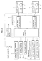
- FIGs. 1 to 5 are diagrams showing the first embodiment of the present invention. First, the structure of the embodiment will be described with reference to Fig. 1.
- a control means 1 comprises a micro computer 2, a right motor control portion 3 and a left motor control portion 4.
- the right motor control portion 3 and left motor control portion 4 are connected to a right head lamp 5 and left head lamp 6 as each corresponding front lamp.
- Each head lamp 5, 6 is provided with a stepping motor 7 and a bulb 8.
- a power supply 9 is connected to not only the bulbs 8 of the head lamps 5, 6 but also the micro computer 2 of the control means 1 through a power supply circuit 10.
- a steering wheel condition detecting means 11 for detecting the steering direction and steering angle of the steering wheel
- a vehicle velocity detecting means 12 for detecting vehicle velocity
- a head lamp switch 13 for turning ON the head lamps 5, 6, and a blinker condition detecting means 14 for detecting blinker operating condition and indicating direction
- the blinker condition detecting means 14 comprises a right turn signal switch 15 and a left blinker switch 16.
- the right turn signal switch 15 or left blinker switch 16 is turned into operating condition selectively depending on the direction of turning a blinker lever (not shown).
- FIGs. 2 and 3 are diagrams showing the structure of the right head lamp 5 on the right side.
- a unit 17 is provided with a reflector 18, a movable reflector 19 and the bule8.
- an inner face of the unit 17 acts as the reflector 8 and the bulb 18 is provided in the center thereof.
- the movable reflector 19 is provided as a light distribution means above the bulb 8.
- the movable reflector 19 is rotated to the right and left within a predetermined angle range by the stepping motor 7 provided on the top of the unit 17. More specifically, the stepping motor 7 has four phases and rotates the movable reflector 19 for distributing diffused light at an angle of 0.15° for every step of the stepping motor 7.
- the rotation range of the movable reflector 19 is 30° in each direction of the right and left from the front, totaling 60°.
- the rotation speed of the movable reflector 19 is 60°/sec (the driving frequency of the stepping motor 7 is 400pps).
- the reflector 18 is fixed and indicates a concentrated light distribution pattern for projecting light of the bulb 8 far in a straight direction.
- the movable reflector 19 located above the bulb 8 indicates a diffused light distribution pattern for beaming a range nearby with a wide angle.
- step 1 in interruption processing execution frequency setting of step 1, the driving frequency of the stepping motor 7 is set up. Because the driving frequency is 400pps, the frequency is set to 25 msec.
- step 2 a signal detected by the steering wheel condition detecting means 11 is read out and in step 3, the steering direction and steering angle are determined.
- step 4 vehicle velocity is read by the vehicle velocity detecting means 12 so as to determine vehicle velocity.
- step 5 whether the head lamps (H/L) 5, 6 are ON or OFF is determined and if OFF, the processing returns to step 2. If ON, the processing proceeds to step 6, in which whether or not the vehicle velocity is below a predetermined value (30 km/h) is determined.
- step 7 the movable angle of the movable reflector 19 is unconditionally calculated with respect to the steering angle of the steering wheel so as to set up target pulse values of the movable reflectors 19 in the head lamps 5, 6 in the steering direction. If the steering wheel is turned to the right, the movable reflector 19 of the head lamp 5 on the right is turned to the right by an amount corresponding to the steering angle of the steering wheel. If the steering wheel is turned to the left, the movable reflector 19 of the head lamp 6 on the left is turned to the left by an amount corresponding to the steering angle of the steering wheel.
- a right blinker signal is recognized in step 8. If the right blinker is ON, the target pulse value (Rt) of the movable reflector 19 is set to 400 which is a maximum value on the right side in step 9 and then, the processing returns to step 2. If the right blinker is OFF, a left blinker signal is recognized in step 10. If the left blinker is ON, the target pulse value (Lt) of the movable reflector 19 is set to 0, which is a maximum value on the left side and then, the processing returns to step 2. If the left blinker is also OFF, the processing goes to step 7, in which the same processing as when the vehicle velocity is higher than 30 km/h is carried out and then, the processing returns to step 2.
- Fig. 5 shows a condition that the right blinker is operated so as to turn the vehicle 20 to the right at an intersection. Because only the right head lamp 5 and the movable reflector 19 are turned, the reflector 18 of the right head lamp 5, and the reflector 18 and movable reflector 19 of the left head lamp 6 remain oriented to the straight advancing direction.
- a turning direction by turning the diffused light distribution pattern B to the right while maintaining the concentrated light distribution pattern A in the straight advancing direction. Because a turning destination can be beamed at a blinker operating stage before the steering wheel is operated, visibility at the time of cornering can be intensified.
- the diffused light distribution pattern B is changed only when the vehicle velocity is lowered to less than a predetermined value for cornering so as to operate the blinker and a case where the blinker is operated to change a lane while traveling at high speeds is excluded. Therefore, unnecessary action of the stepping motor 7 for each of the head lamps 5, 6 is eliminated thereby improving the durability of the movable reflector 19 and the like and eliminating dazzling to other vehicle. Further, because if a driver forgets operation of the blinker, the turning destination is not beamed, there is an effect that the driver is urged to operate the blinker.
- the rotation speed of the movable reflector 19 is not fixed, but may be increased more by detecting the steering speed of the steering wheel (may be increased twice for example). As a result, even if the operation of the blinker is delayed so that it is operated at the same time when the steering wheel is operated or the blinker is operated slightly later than the steering wheel is operated, there is obtained an effect that an beam angle of the movable reflector 19 is changed to a maximum angle.
- the reflector 19 is rotated quickly up to the maximum angle, the reflector is preferred to be returned slowly at a speed corresponding to the speed of the steering angle of the steering wheel.
- the change in brightness of driver's visibility is small so that there is no sense of disharmony.
- Figs. 6 and 7 are diagrams showing a second embodiment of the present invention. Step 1 to step 8 of a flow chart of Fig. 6 are the same as the first embodiment. A different point is that when the right blinker is ON in step 8 or when the left blinker is ON in step 12, the target pulse value (Rt) of the right movable reflector 19 is set to 400, which is a maximum value on the right side while the target pulse value (Lt) of the left movable reflector 19 is set to 0, which is a maximum value on the left side. Therefore, the both movable reflectors 19 are changed to a maximum extent in outward direction if any of the right and left blinkers is operated.
- the target pulse value (Rt) of the right movable reflector 19 is set to 400, which is a maximum value on the right side while the target pulse value (Lt) of the left movable reflector 19 is set to 0, which is a maximum value on the left side. Therefore, the both movable reflectors 19 are changed to a maximum extent
- Fig. 7 shows a condition that when a driver intends to turn the vehicle 20 to the right at an intersection, the right blinker is operated. In this case, not only the diffused light distribution pattern B to the right but also the diffused light distribution pattern C to the left can be obtained, so that the safety can be confirmed more easily.
- Figs. 8 and 9 are diagrams showing a third embodiment of the present invention.
- a hazard switch 21 is connected to the control means 1.
- the flow chart of Fig. 9 is the same as the second embodiment except that a step 15 for determining whether the hazard switch 21 is ON or OFF.
- the vehicle When the hazard switch 21 is operated, the vehicle is in emergency traveling condition like pulling a vehicle in trouble.
- the step 15 about the hazard switch 21 even if the vehicle velocity is as low as less than 30 km/h, the function of maximizing the rotation of the movable reflector 19 by operating the blinker is canceled, so that movable reflector 19 is turned by an amount corresponding to the steering angle of the steering wheel in its steering direction. Therefore, when a vehicle is in such emergency traveling condition like pulling another vehicle in trouble, it never dazzles the other vehicles.
Landscapes
- Engineering & Computer Science (AREA)
- Mechanical Engineering (AREA)
- Lighting Device Outwards From Vehicle And Optical Signal (AREA)
Abstract
Description
- The present invention relates to a vehicle front lamp light distribution control system and more particularly to a vehicle front lamp light distribution control system capable of raising visibility at the time of cornering by controlling light distribution means of the front lamp.
- According to Japanese Patent Publication No. H5-23216, Japanese Patent Application Laid-Open No. H8-183385, Japanese Patent Application Laid-Open No. H11-78675 and Japanese Patent Application Laid-Open No. H8-192674 a vehicle head lamp including a fog lamp is provided with a movable reflector and by turning the movable reflector in the steering direction by an amount corresponding to a steering angle of the steering wheel, the light distribution pattern of the front lamp is changed in the direction of vehicle's turn so as to raise visibility at the time of cornering.
- However, according to the aforementioned earlier art, the light distribution pattern of the front lamp is changed in the steering direction of the steering wheel by an amount corresponding to the steering angle when the vehicle turns on an intersection or the like, cornering destination cannot be beamed brightly enough before operating the steering wheel. Therefore, an art capable of beaming the cornering destination prior to operation of the steering wheel has been demanded.
- Accordingly, the present invention has been achieved to meet the above described demands and therefore, an object of the invention is to provide a vehicle front lamp light distribution control system capable of raising visibility at the time of cornering by beaming a turning destination before the steering wheel is operated.
- To achieve the above described object, according to a first aspect of the present invention, there is provided a vehicle front lamp light distribution control system comprising: a light distribution means provided on each of front lamps on the right and left sides of a front face of a vehicle for changing beam angles in the right/left direction; a steering wheel condition detecting means for detecting a steering direction and a steering angle of the steering wheel; a blinker condition detecting means for detecting an operating condition and an indication direction of the blinker; and a control means for changing an beam angle of the light distribution means on a side corresponding to the steering direction of the steering wheel in a steering direction of the steering wheel by an amount corresponding to a steering angle thereof by inputting signals from the vehicle velocity detecting means and the blinker condition detecting means, wherein the control means changes the beam angle of the light distribution means on the side corresponding to the indication direction of the blinker in the indication direction to a maximum extent only when the vehicle velocity is lower than a predetermined value and the blinker is operated.
- According to the first aspect of the present invention, the beam angle of the light distribution means located on a side corresponding to the indication direction of the blinker can be changed to a maximum extent when the blinker is operated before the steering wheel is operated. Thus, before operating the steering wheel, a turning destination can be beamed brightly so as to raise visibility at the time of cornering. The beam angle of the light distribution means is changed to a maximum extent only when the vehicle velocity is reduced to less than a predetermined value for cornering and then, the blinker is operated. Thus, a case where the blinker is operated for changing a lane while traveling at high speeds is excluded. Thus, unnecessary action of the light distribution means is eliminated thereby improving the durability of the driving portion and eliminating dazzling to other vehicles. In the meantime, if only the steering wheel is operated without operating the blinker, the beam angle of the light distribution means is changed in the steering direction of the steering wheel by an amount corresponding to the steering angle like conventionally. Because the turning destination is not beamed if a driver forgets to operate the blinker, there is an advantage that the driver is urged to operate the blinker.
- According to a second aspect of the present invention, there is provided a vehicle front lamp light distribution control system comprising: a light distribution means provided on each of front lamps on the right and left sides of a front face of a vehicle for changing beam angles in the right/left direction; a steering wheel condition detecting means for detecting a steering direction and a steering angle of the steering wheel; a blinker condition detecting means for detecting an operating condition and an indication direction of the blinker; and a control means for changing an beam angle of the light distribution means on a side corresponding to the steering direction of the steering wheel in a steering direction of the steering wheel by an amount corresponding to a steering angle thereof by inputting signals from the vehicle velocity detecting means and the blinker condition detecting means, wherein the control means changes the beam angle of the light distribution means on both the right and left sides only when the vehicle velocity is lower than a predetermined value and the blinker is operated.
- According to the second aspect of the present invention, the beam angles of the light distribution means on both the right and left sides are changed to maximum extent outward of each even if any of the right and left blinkers is operated. Therefore, the turning destination can be beamed brightly and at the same time, it is possible to confirm whether or not any vehicle comes from an opposite direction.
- According to a third aspect of the present invention, there is provided a vehicle front lamp light distribution control system according to the first or second aspect, further comprising a hazard detecting means for detecting an operating condition of the hazard switch, wherein when the hazard switch is operated, the function for maximizing the beam angle of the light distribution means to a maximum extent is canceled when the blinker is operated even if the vehicle velocity is less than a predetermined value, so that the beam angle of the light distribution means is changed in the steering direction of the steering wheel by an amount corresponding to the steering angle thereof.
- When the hazard switch is operated, the vehicle is in emergency traveling condition like pulling a vehicle in trouble. Thus, according to the third aspect of the invention, even if the vehicle velocity is less than a predetermined value, the function of maximizing the beam angle of the light distribution means is canceled, so that the beam angle of the light distribution means is changed in the steering direction of the steering wheel by an amount corresponding to the steering angle.
- According to a fourth aspect of the present invention, when the beam angle of the light distribution means is changed to a maximum extent, the beam angle of the light distribution means is changed at a speed higher than the steering angle of the steering wheel.
- Because according to the fourth aspect of the present invention, the beam angle of the light distribution means is changed more quickly than the steering angle of the steering wheel when the beam angle of the light distribution means is changed to a maximum extent, the operation of the blinker is delayed so that the blinker is operated at the same time as when the steering wheel is operated or the blinker is operated slightly later than the steering wheel. Consequently, the beam angle of the light distribution means can be changed to the maximum extent.
- According to a fifth aspect of the present invention, when returning the light distribution means whose beam angle is changed to a maximum extent, the beam angle is changed at a speed corresponding to a change in the steering angle of the steering wheel.
- According to the fifth aspect of the present invention, because the speed of returning the beam angle of the light distribution means changed to the maximum extent is slow, the change in brightness of driver's visibility is small, so that there is no sense of disharmony.
- According to a sixth aspect of the present invention, the light distribution means is a movable reflector for changing a diffused light distribution pattern provided above an optical axis of the reflector of the front lamp.
- According to the sixth aspect of the present invention, as the light distribution means is a movable reflector provided above an optical axis of the reflector of the front lamp, it is possible to change the diffused light distribution pattern alone in a turning direction while maintaining the concentrated light distribution pattern in the straight advancing direction by means of a reflector other than the movable reflector. Therefore, both the turning direction (an opposite direction also in the aforementioned two aspects) and the straight advancing direction can be beamed brightly.
-
- Fig. 1 is a block diagram showing the structure of a first embodiment of the present invention;
- Fig. 2 is a front view showing a head lamp;
- Fig. 3 is a sectional view of the head lamp;
- Fig. 4 is a flow chart showing control according to the first embodiment;
- Fig. 5 is a plan view of an intersection showing light distribution pattern of the first embodiment;
- Fig. 6 is a flow chart showing control according to a second embodiment;
- Fig. 7 is a plan view of an intersection showing light distribution pattern of the second embodiment;
- Fig. 8 is a block diagram showing the structure of a third embodiment; and
- Fig. 9 is a flow chart showing control according to a third embodiment.
-
- Hereinafter, the preferred embodiments of the present invention will be described with reference to the accompanying drawings.
- Figs. 1 to 5 are diagrams showing the first embodiment of the present invention. First, the structure of the embodiment will be described with reference to Fig. 1. A control means 1 comprises a
micro computer 2, a rightmotor control portion 3 and a leftmotor control portion 4. The rightmotor control portion 3 and leftmotor control portion 4 are connected to aright head lamp 5 andleft head lamp 6 as each corresponding front lamp. Eachhead lamp stepping motor 7 and abulb 8. Apower supply 9 is connected to not only thebulbs 8 of thehead lamps micro computer 2 of the control means 1 through apower supply circuit 10. - Further, a steering wheel condition detecting means 11 for detecting the steering direction and steering angle of the steering wheel, a vehicle velocity detecting means 12 for detecting vehicle velocity, a
head lamp switch 13 for turning ON thehead lamps micro computer 2. The blinker condition detecting means 14 comprises a rightturn signal switch 15 and aleft blinker switch 16. The rightturn signal switch 15 orleft blinker switch 16 is turned into operating condition selectively depending on the direction of turning a blinker lever (not shown). - Figs. 2 and 3 are diagrams showing the structure of the
right head lamp 5 on the right side. Aunit 17 is provided with areflector 18, amovable reflector 19 and the bule8. In details, an inner face of theunit 17 acts as thereflector 8 and thebulb 18 is provided in the center thereof. Themovable reflector 19 is provided as a light distribution means above thebulb 8. Themovable reflector 19 is rotated to the right and left within a predetermined angle range by thestepping motor 7 provided on the top of theunit 17. More specifically, the steppingmotor 7 has four phases and rotates themovable reflector 19 for distributing diffused light at an angle of 0.15° for every step of the steppingmotor 7. The rotation range of themovable reflector 19 is 30° in each direction of the right and left from the front, totaling 60°. The rotation speed of themovable reflector 19 is 60°/sec (the driving frequency of thestepping motor 7 is 400pps). Thereflector 18 is fixed and indicates a concentrated light distribution pattern for projecting light of thebulb 8 far in a straight direction. Themovable reflector 19 located above thebulb 8 indicates a diffused light distribution pattern for beaming a range nearby with a wide angle. - Thus, it is possible to change the diffused light distribution pattern alone in a turning direction by means of the
movable reflector 19 while maintaining the concentrated light distribution pattern in the straight advancing direction by means of thefixed reflector 18. - Next, a control flow with the control means 1 will be described with reference to the flow chart of Fig. 4. First, in interruption processing execution frequency setting of
step 1, the driving frequency of the steppingmotor 7 is set up. Because the driving frequency is 400pps, the frequency is set to 25 msec. Instep 2, a signal detected by the steering wheelcondition detecting means 11 is read out and instep 3, the steering direction and steering angle are determined. Instep 4, vehicle velocity is read by the vehiclevelocity detecting means 12 so as to determine vehicle velocity. Next, instep 5, whether the head lamps (H/L) 5, 6 are ON or OFF is determined and if OFF, the processing returns to step 2. If ON, the processing proceeds to step 6, in which whether or not the vehicle velocity is below a predetermined value (30 km/h) is determined. - If the vehicle velocity is higher than 30 km/h, in
step 7, the movable angle of themovable reflector 19 is unconditionally calculated with respect to the steering angle of the steering wheel so as to set up target pulse values of themovable reflectors 19 in thehead lamps movable reflector 19 of thehead lamp 5 on the right is turned to the right by an amount corresponding to the steering angle of the steering wheel. If the steering wheel is turned to the left, themovable reflector 19 of thehead lamp 6 on the left is turned to the left by an amount corresponding to the steering angle of the steering wheel. - Then, if it is determined that the vehicle velocity is less than 30 km/h in
step 6, a right blinker signal is recognized instep 8. If the right blinker is ON, the target pulse value (Rt) of themovable reflector 19 is set to 400 which is a maximum value on the right side instep 9 and then, the processing returns to step 2. If the right blinker is OFF, a left blinker signal is recognized instep 10. If the left blinker is ON, the target pulse value (Lt) of themovable reflector 19 is set to 0, which is a maximum value on the left side and then, the processing returns to step 2. If the left blinker is also OFF, the processing goes to step 7, in which the same processing as when the vehicle velocity is higher than 30 km/h is carried out and then, the processing returns to step 2. - As described above, according to this embodiment, it is so controlled that when the right blinker is operated, the
movable reflector 19 of theright head lamp 5 is at the maximum angle to the right and when the left blinker is operated, themovable reflector 19 of theleft head lamp 6 is at the maximum angle to the left. Fig. 5 shows a condition that the right blinker is operated so as to turn thevehicle 20 to the right at an intersection. Because only theright head lamp 5 and themovable reflector 19 are turned, thereflector 18 of theright head lamp 5, and thereflector 18 andmovable reflector 19 of theleft head lamp 6 remain oriented to the straight advancing direction. Therefore, it is possible to beam a turning direction by turning the diffused light distribution pattern B to the right while maintaining the concentrated light distribution pattern A in the straight advancing direction. Because a turning destination can be beamed at a blinker operating stage before the steering wheel is operated, visibility at the time of cornering can be intensified. The diffused light distribution pattern B is changed only when the vehicle velocity is lowered to less than a predetermined value for cornering so as to operate the blinker and a case where the blinker is operated to change a lane while traveling at high speeds is excluded. Therefore, unnecessary action of the steppingmotor 7 for each of thehead lamps movable reflector 19 and the like and eliminating dazzling to other vehicle. Further, because if a driver forgets operation of the blinker, the turning destination is not beamed, there is an effect that the driver is urged to operate the blinker. - The rotation speed of the
movable reflector 19 is not fixed, but may be increased more by detecting the steering speed of the steering wheel (may be increased twice for example). As a result, even if the operation of the blinker is delayed so that it is operated at the same time when the steering wheel is operated or the blinker is operated slightly later than the steering wheel is operated, there is obtained an effect that an beam angle of themovable reflector 19 is changed to a maximum angle. - Then, in case where the
movable reflector 19 is rotated quickly up to the maximum angle, the reflector is preferred to be returned slowly at a speed corresponding to the speed of the steering angle of the steering wheel. As a result, the change in brightness of driver's visibility is small so that there is no sense of disharmony. - Figs. 6 and 7 are diagrams showing a second embodiment of the present invention.
Step 1 to step 8 of a flow chart of Fig. 6 are the same as the first embodiment. A different point is that when the right blinker is ON instep 8 or when the left blinker is ON instep 12, the target pulse value (Rt) of the rightmovable reflector 19 is set to 400, which is a maximum value on the right side while the target pulse value (Lt) of the leftmovable reflector 19 is set to 0, which is a maximum value on the left side. Therefore, the bothmovable reflectors 19 are changed to a maximum extent in outward direction if any of the right and left blinkers is operated. Consequently, the turning destination can be beamed brightly and at the same time, it can be recognized that no vehicle or the like comes from an opposite side. That is, Fig. 7 shows a condition that when a driver intends to turn thevehicle 20 to the right at an intersection, the right blinker is operated. In this case, not only the diffused light distribution pattern B to the right but also the diffused light distribution pattern C to the left can be obtained, so that the safety can be confirmed more easily. - Figs. 8 and 9 are diagrams showing a third embodiment of the present invention. According to the third embodiment, as shown in Fig. 8, a
hazard switch 21 is connected to the control means 1. Then, the flow chart of Fig. 9 is the same as the second embodiment except that astep 15 for determining whether thehazard switch 21 is ON or OFF. - When the
hazard switch 21 is operated, the vehicle is in emergency traveling condition like pulling a vehicle in trouble. Thus, by adding thestep 15 about thehazard switch 21, even if the vehicle velocity is as low as less than 30 km/h, the function of maximizing the rotation of themovable reflector 19 by operating the blinker is canceled, so thatmovable reflector 19 is turned by an amount corresponding to the steering angle of the steering wheel in its steering direction. Therefore, when a vehicle is in such emergency traveling condition like pulling another vehicle in trouble, it never dazzles the other vehicles.
Claims (6)
- A vehicle front lamp light distribution control system, comprising:a light distribution means provided on each of front lamps on the right and left sides of a front face of a vehicle for changing beam angles in the right/left direction;a steering wheel condition detecting means for detecting a steering direction and a steering angle of the steering wheel;a blinker condition detecting means for detecting an operating condition and an indication direction of the blinker; anda control means for changing an beam angle of the light distribution means on a side corresponding to the steering direction of the steering wheel in a steering direction of the steering wheel by an amount corresponding to a steering angle thereof by inputting signals from the vehicle velocity detecting means and the blinker condition detecting means, whereinsaid control means changes the beam angle of the light distribution means on the side corresponding to the indication direction of the blinker in the indication direction to a maximum extent only when the vehicle velocity is lower than a predetermined value and the blinker is operated.
- A vehicle front lamp light distribution control system, comprising:a light distribution means provided on each of front lamps on the right and left sides of a front face of a vehicle for changing beam angles in the right/left direction;a steering wheel condition detecting means for detecting a steering direction and a steering angle of the steering wheel;a blinker condition detecting means for detecting an operating condition and an indication direction of the blinker; anda control means for changing an beam angle of the light distribution means on a side corresponding to the steering direction of the steering wheel in a steering direction of the steering wheel by an amount corresponding to a steering angle thereof by inputting signals from the vehicle velocity detecting means and the blinker condition detecting means, whereinsaid control means changes the beam angle of the light distribution means on both the right and left sides only when the vehicle velocity is lower than a predetermined value and the blinker is operated.
- A vehicle front lamp light distribution control system as claimed in claim 1 or 2, further comprising:a hazard detecting means for detecting an operating condition of the hazard switch, whereinwhen the hazard switch is operated, the function for maximizing the beam angle of the light distribution means to a maximum extent is canceled when the blinker is operated even if the vehicle velocity is less than a predetermined value, so that the beam angle of the light distribution means is changed in the steering direction of the steering wheel by an amount corresponding to the steering angle thereof.
- A vehicle front lamp light distribution control system as claimed in claim 1 or 2, wherein
when the beam angle of the light distribution means is changed to a maximum extent, the beam angle of the light distribution means is changed at a speed higher than the steering angle of the steering wheel. - A vehicle front lamp light distribution control system as claimed in claim 4, wherein
when returning the light distribution means whose beam angle is changed to a maximum extent, the beam angle is changed at a speed corresponding to a change in the steering angle of the steering wheel. - A vehicle front lamp light distribution control system as claimed in claim 1 or 2, wherein
the light distribution means is a movable reflector for changing a diffused light distribution pattern provided above an optical axis of the reflector of the front lamp.
Applications Claiming Priority (2)
| Application Number | Priority Date | Filing Date | Title |
|---|---|---|---|
| JP2000089941 | 2000-03-28 | ||
| JP2000089941A JP2001270382A (en) | 2000-03-28 | 2000-03-28 | Head lamp light distribution control system for vehicle |
Publications (3)
| Publication Number | Publication Date |
|---|---|
| EP1138550A2 true EP1138550A2 (en) | 2001-10-04 |
| EP1138550A3 EP1138550A3 (en) | 2004-02-25 |
| EP1138550B1 EP1138550B1 (en) | 2008-04-30 |
Family
ID=18605622
Family Applications (1)
| Application Number | Title | Priority Date | Filing Date |
|---|---|---|---|
| EP01107948A Expired - Lifetime EP1138550B1 (en) | 2000-03-28 | 2001-03-28 | Vehicle front lamp light distribution control system |
Country Status (5)
| Country | Link |
|---|---|
| US (1) | US6547424B2 (en) |
| EP (1) | EP1138550B1 (en) |
| JP (1) | JP2001270382A (en) |
| KR (1) | KR100492870B1 (en) |
| DE (1) | DE60133790T2 (en) |
Cited By (4)
| Publication number | Priority date | Publication date | Assignee | Title |
|---|---|---|---|---|
| EP1375250A2 (en) * | 2002-06-26 | 2004-01-02 | Denso Corporation | Automatic beam-axis adjustment system for vehicular headlights |
| WO2008156430A1 (en) * | 2007-06-18 | 2008-12-24 | Hella Saturnus Slovenija, Proizvodnja Svetlobne Opreme Za Motorna In Druga Vozila | Device and process for control of cornering lights in motor vehicles |
| CN102371939A (en) * | 2010-08-05 | 2012-03-14 | 罗伯特·博世有限公司 | Method and equipment for determining recommendation for radiation characteristics of headlight of vehicle |
| CN105501106A (en) * | 2015-12-18 | 2016-04-20 | 重庆工商职业学院 | Automobile steering system and vehicle adopting same |
Families Citing this family (16)
| Publication number | Priority date | Publication date | Assignee | Title |
|---|---|---|---|---|
| JP2002326537A (en) * | 2001-05-07 | 2002-11-12 | Koito Mfg Co Ltd | Lighting system for vehicle |
| JP2003054312A (en) * | 2001-08-21 | 2003-02-26 | Koito Mfg Co Ltd | Vehicle headlight device |
| JP2003112567A (en) * | 2001-10-04 | 2003-04-15 | Koito Mfg Co Ltd | Lighting device for vehicle |
| JP2003112569A (en) * | 2001-10-04 | 2003-04-15 | Koito Mfg Co Ltd | Lighting device for vehicle |
| US7156542B2 (en) * | 2002-12-13 | 2007-01-02 | Ford Global Technologies, Llc | Vehicle headlight system having digital beam-forming optics |
| JP4330922B2 (en) * | 2003-05-09 | 2009-09-16 | 株式会社小糸製作所 | Vehicle lighting device |
| DE10346508B4 (en) * | 2003-10-02 | 2007-10-11 | Daimlerchrysler Ag | Device for improving the visibility in a motor vehicle |
| JP4501888B2 (en) * | 2005-07-07 | 2010-07-14 | 株式会社デンソー | Vehicle headlamp device |
| US20080055918A1 (en) * | 2006-08-31 | 2008-03-06 | Anthony Peter Mascadri | Vehicular lamp assembly having multiple moveable reflectors |
| JP5170643B2 (en) | 2008-01-25 | 2013-03-27 | スタンレー電気株式会社 | Vehicle cornering lamp |
| US20110204203A1 (en) * | 2010-02-23 | 2011-08-25 | Miller Douglas C | Steerable vehicle lighting system |
| US10220770B2 (en) | 2011-07-08 | 2019-03-05 | Sl Corporation | Guide lamp for vehicle |
| KR101295833B1 (en) * | 2011-07-08 | 2013-08-12 | 에스엘 주식회사 | Automotive turn signal lamp and cotrolling method for the same |
| DE102011081412B4 (en) * | 2011-08-23 | 2020-10-29 | Robert Bosch Gmbh | Method and device for adapting a light emission from at least one headlight of a vehicle |
| JP6751307B2 (en) * | 2016-05-17 | 2020-09-02 | スタンレー電気株式会社 | Vehicle lighting |
| JP6901348B2 (en) * | 2017-08-22 | 2021-07-14 | スタンレー電気株式会社 | Vehicle lighting control device |
Citations (4)
| Publication number | Priority date | Publication date | Assignee | Title |
|---|---|---|---|---|
| US5562336A (en) * | 1995-02-07 | 1996-10-08 | Honda Giken Kogyo Kabushiki Kaisha | Head lamp device for vehicle |
| US5711590A (en) * | 1994-12-29 | 1998-01-27 | Honda Giken Kogyo Kabushiki Kaisha | Headlight having variable light distribution |
| DE19755406A1 (en) * | 1996-12-13 | 1998-07-09 | Koito Mfg Co Ltd | Vehicle lighting control device |
| DE19756574A1 (en) * | 1996-12-18 | 1998-10-08 | Koito Mfg Co Ltd | Lighting unit for a vehicle |
Family Cites Families (19)
| Publication number | Priority date | Publication date | Assignee | Title |
|---|---|---|---|---|
| US4663696A (en) * | 1985-01-31 | 1987-05-05 | Koito Siesakusho Co., Ltd. | Dual purpose lamp assembly for use, for example, as a combined fog and cornering lamp on a motor vehicle |
| FR2587947B1 (en) * | 1985-09-30 | 1990-06-29 | Koito Mfg Co Ltd | CORNER LIGHTING SYSTEM FOR VEHICLE |
| JPS6467439A (en) * | 1987-09-08 | 1989-03-14 | Koito Mfg Co Ltd | Cornering lamp system for vehicle |
| JPS6467440A (en) * | 1987-09-08 | 1989-03-14 | Koito Mfg Co Ltd | Cornering lamp system for vehicle |
| JPH03111153A (en) | 1989-09-25 | 1991-05-10 | Daido Kogyo Co Ltd | Work turning over device |
| JPH0523216A (en) | 1991-07-18 | 1993-02-02 | Sharp Corp | Charge type motor-driven tooth brush |
| JP2783079B2 (en) * | 1992-08-28 | 1998-08-06 | トヨタ自動車株式会社 | Light distribution control device for headlamp |
| JP2633169B2 (en) * | 1992-11-19 | 1997-07-23 | 株式会社小糸製作所 | Cornering lamp system for vehicles |
| JP3208697B2 (en) * | 1993-12-28 | 2001-09-17 | 株式会社小糸製作所 | Cornering lamp system for vehicles |
| JP2832573B2 (en) * | 1993-12-28 | 1998-12-09 | 株式会社小糸製作所 | Cornering lamp system for vehicles |
| US5550717A (en) * | 1994-02-04 | 1996-08-27 | Liao; Winner | Direction turning device for a headlight of an automobile |
| JP3289493B2 (en) * | 1994-06-21 | 2002-06-04 | 市光工業株式会社 | Automatic headlight irradiation direction control mechanism for automobiles |
| JP3284790B2 (en) * | 1994-11-09 | 2002-05-20 | 市光工業株式会社 | Automatic headlight irradiation direction control mechanism for automobiles |
| JP3111153B2 (en) * | 1995-01-17 | 2000-11-20 | 本田技研工業株式会社 | Headlight device for vehicles |
| JPH09315214A (en) * | 1996-05-29 | 1997-12-09 | Honda Motor Co Ltd | Headlight device for vehicle |
| JP3622808B2 (en) * | 1996-06-03 | 2005-02-23 | 本田技研工業株式会社 | Vehicle headlamp device |
| JPH10203232A (en) * | 1997-01-29 | 1998-08-04 | Honda Motor Co Ltd | Headlamp device for vehicle |
| JP3526181B2 (en) | 1997-09-12 | 2004-05-10 | 本田技研工業株式会社 | Vehicle headlights |
| DE19946350A1 (en) * | 1999-09-28 | 2001-03-29 | Bosch Gmbh Robert | Projection headlamp for illumination arrangement for motor vehicle has reflector rotatable together with light source about rotation axis near second main point of projection lens |
-
2000
- 2000-03-28 JP JP2000089941A patent/JP2001270382A/en active Pending
-
2001
- 2001-03-26 KR KR10-2001-0015543A patent/KR100492870B1/en not_active IP Right Cessation
- 2001-03-28 DE DE60133790T patent/DE60133790T2/en not_active Expired - Lifetime
- 2001-03-28 EP EP01107948A patent/EP1138550B1/en not_active Expired - Lifetime
- 2001-03-28 US US09/818,913 patent/US6547424B2/en not_active Expired - Fee Related
Patent Citations (4)
| Publication number | Priority date | Publication date | Assignee | Title |
|---|---|---|---|---|
| US5711590A (en) * | 1994-12-29 | 1998-01-27 | Honda Giken Kogyo Kabushiki Kaisha | Headlight having variable light distribution |
| US5562336A (en) * | 1995-02-07 | 1996-10-08 | Honda Giken Kogyo Kabushiki Kaisha | Head lamp device for vehicle |
| DE19755406A1 (en) * | 1996-12-13 | 1998-07-09 | Koito Mfg Co Ltd | Vehicle lighting control device |
| DE19756574A1 (en) * | 1996-12-18 | 1998-10-08 | Koito Mfg Co Ltd | Lighting unit for a vehicle |
Cited By (6)
| Publication number | Priority date | Publication date | Assignee | Title |
|---|---|---|---|---|
| EP1375250A2 (en) * | 2002-06-26 | 2004-01-02 | Denso Corporation | Automatic beam-axis adjustment system for vehicular headlights |
| EP1375250A3 (en) * | 2002-06-26 | 2005-08-10 | Denso Corporation | Automatic beam-axis adjustment system for vehicular headlights |
| WO2008156430A1 (en) * | 2007-06-18 | 2008-12-24 | Hella Saturnus Slovenija, Proizvodnja Svetlobne Opreme Za Motorna In Druga Vozila | Device and process for control of cornering lights in motor vehicles |
| CN102371939A (en) * | 2010-08-05 | 2012-03-14 | 罗伯特·博世有限公司 | Method and equipment for determining recommendation for radiation characteristics of headlight of vehicle |
| CN102371939B (en) * | 2010-08-05 | 2015-11-25 | 罗伯特·博世有限公司 | For determining the method and apparatus of the suggestion of the illumination characteristic of at least one car light to vehicle |
| CN105501106A (en) * | 2015-12-18 | 2016-04-20 | 重庆工商职业学院 | Automobile steering system and vehicle adopting same |
Also Published As
| Publication number | Publication date |
|---|---|
| US20010026451A1 (en) | 2001-10-04 |
| KR20010093691A (en) | 2001-10-29 |
| DE60133790T2 (en) | 2009-06-25 |
| EP1138550B1 (en) | 2008-04-30 |
| KR100492870B1 (en) | 2005-05-31 |
| JP2001270382A (en) | 2001-10-02 |
| US6547424B2 (en) | 2003-04-15 |
| EP1138550A3 (en) | 2004-02-25 |
| DE60133790D1 (en) | 2008-06-12 |
Similar Documents
| Publication | Publication Date | Title |
|---|---|---|
| EP1138550B1 (en) | Vehicle front lamp light distribution control system | |
| US7156542B2 (en) | Vehicle headlight system having digital beam-forming optics | |
| JP3865574B2 (en) | Vehicle headlight system | |
| US6293686B1 (en) | Lighting device for vehicles | |
| US20070002571A1 (en) | Adaptive lighting system for motor vehicles | |
| US8648535B2 (en) | Vehicle lamp control apparatus | |
| US7210828B2 (en) | Vehicle lighting system | |
| JP2003112569A (en) | Lighting device for vehicle | |
| US8757853B2 (en) | Method for controlling a vehicle headlamp | |
| JP3075966B2 (en) | Headlight device for vehicles | |
| US20020196634A1 (en) | Apparatus for a motor vehicle, for lighting bends negotiated by the vehicle | |
| US6578992B2 (en) | Vehicular lamp system for automotive vehicle | |
| EP2394851A2 (en) | Vehicle lighting system | |
| JP2007246060A (en) | Headlight device for vehicle | |
| JP2000293799A (en) | Lighting controller for automatic following running system | |
| EP2196357B1 (en) | Vehicular illumination device | |
| US7150547B2 (en) | Turn signal and steering responsive adjustable lighting apparatus for vehicle | |
| US20070109762A1 (en) | Method for optimizing a vehicle light and corresponding headlight device | |
| JP2002234383A (en) | Variable light distribution head lamp system | |
| JP2002225618A (en) | Headlight system for vehicle | |
| JP4002071B2 (en) | Vehicle headlight system | |
| JPS6064044A (en) | Car head light controller | |
| JP2005289268A (en) | Lamp system for vehicle | |
| KR0158298B1 (en) | Headlamp aiming control device | |
| JP2966608B2 (en) | Automatic headlight dimmer |
Legal Events
| Date | Code | Title | Description |
|---|---|---|---|
| PUAI | Public reference made under article 153(3) epc to a published international application that has entered the european phase |
Free format text: ORIGINAL CODE: 0009012 |
|
| 17P | Request for examination filed |
Effective date: 20010328 |
|
| AK | Designated contracting states |
Kind code of ref document: A2 Designated state(s): AT BE CH CY DE DK ES FI FR GB GR IE IT LI LU MC NL PT SE TR |
|
| AX | Request for extension of the european patent |
Free format text: AL;LT;LV;MK;RO;SI |
|
| PUAL | Search report despatched |
Free format text: ORIGINAL CODE: 0009013 |
|
| AK | Designated contracting states |
Kind code of ref document: A3 Designated state(s): AT BE CH CY DE DK ES FI FR GB GR IE IT LI LU MC NL PT SE TR |
|
| AX | Request for extension of the european patent |
Extension state: AL LT LV MK RO SI |
|
| RIC1 | Information provided on ipc code assigned before grant |
Ipc: 7B 60Q 1/12 A |
|
| AKX | Designation fees paid |
Designated state(s): DE FR GB |
|
| 17Q | First examination report despatched |
Effective date: 20061017 |
|
| GRAP | Despatch of communication of intention to grant a patent |
Free format text: ORIGINAL CODE: EPIDOSNIGR1 |
|
| RIN1 | Information on inventor provided before grant (corrected) |
Inventor name: FURUYA, TAKAYUKIC/O ICHIKOH INDUSTRIES, LTD. Inventor name: HASUMI, HIROFUMIC/O ICHIKOH INDUSTRIES, LTD. |
|
| GRAS | Grant fee paid |
Free format text: ORIGINAL CODE: EPIDOSNIGR3 |
|
| GRAA | (expected) grant |
Free format text: ORIGINAL CODE: 0009210 |
|
| AK | Designated contracting states |
Kind code of ref document: B1 Designated state(s): DE FR GB |
|
| REG | Reference to a national code |
Ref country code: GB Ref legal event code: FG4D |
|
| REF | Corresponds to: |
Ref document number: 60133790 Country of ref document: DE Date of ref document: 20080612 Kind code of ref document: P |
|
| ET | Fr: translation filed | ||
| PLBE | No opposition filed within time limit |
Free format text: ORIGINAL CODE: 0009261 |
|
| STAA | Information on the status of an ep patent application or granted ep patent |
Free format text: STATUS: NO OPPOSITION FILED WITHIN TIME LIMIT |
|
| 26N | No opposition filed |
Effective date: 20090202 |
|
| PGFP | Annual fee paid to national office [announced via postgrant information from national office to epo] |
Ref country code: FR Payment date: 20110317 Year of fee payment: 11 |
|
| PGFP | Annual fee paid to national office [announced via postgrant information from national office to epo] |
Ref country code: GB Payment date: 20110323 Year of fee payment: 11 Ref country code: DE Payment date: 20110323 Year of fee payment: 11 |
|
| GBPC | Gb: european patent ceased through non-payment of renewal fee |
Effective date: 20120328 |
|
| REG | Reference to a national code |
Ref country code: FR Ref legal event code: ST Effective date: 20121130 |
|
| REG | Reference to a national code |
Ref country code: DE Ref legal event code: R119 Ref document number: 60133790 Country of ref document: DE Effective date: 20121002 |
|
| PG25 | Lapsed in a contracting state [announced via postgrant information from national office to epo] |
Ref country code: GB Free format text: LAPSE BECAUSE OF NON-PAYMENT OF DUE FEES Effective date: 20120328 Ref country code: FR Free format text: LAPSE BECAUSE OF NON-PAYMENT OF DUE FEES Effective date: 20120402 |
|
| PG25 | Lapsed in a contracting state [announced via postgrant information from national office to epo] |
Ref country code: DE Free format text: LAPSE BECAUSE OF NON-PAYMENT OF DUE FEES Effective date: 20121002 |