EP2196357B1 - Vehicular illumination device - Google Patents
Vehicular illumination device Download PDFInfo
- Publication number
- EP2196357B1 EP2196357B1 EP09177851A EP09177851A EP2196357B1 EP 2196357 B1 EP2196357 B1 EP 2196357B1 EP 09177851 A EP09177851 A EP 09177851A EP 09177851 A EP09177851 A EP 09177851A EP 2196357 B1 EP2196357 B1 EP 2196357B1
- Authority
- EP
- European Patent Office
- Prior art keywords
- light distribution
- lamp
- leveling
- swivel
- radiating
- Prior art date
- Legal status (The legal status is an assumption and is not a legal conclusion. Google has not performed a legal analysis and makes no representation as to the accuracy of the status listed.)
- Revoked
Links
Images


Classifications
-
- B—PERFORMING OPERATIONS; TRANSPORTING
- B60—VEHICLES IN GENERAL
- B60Q—ARRANGEMENT OF SIGNALLING OR LIGHTING DEVICES, THE MOUNTING OR SUPPORTING THEREOF OR CIRCUITS THEREFOR, FOR VEHICLES IN GENERAL
- B60Q1/00—Arrangement of optical signalling or lighting devices, the mounting or supporting thereof or circuits therefor
- B60Q1/02—Arrangement of optical signalling or lighting devices, the mounting or supporting thereof or circuits therefor the devices being primarily intended to illuminate the way ahead or to illuminate other areas of way or environments
- B60Q1/04—Arrangement of optical signalling or lighting devices, the mounting or supporting thereof or circuits therefor the devices being primarily intended to illuminate the way ahead or to illuminate other areas of way or environments the devices being headlights
- B60Q1/06—Arrangement of optical signalling or lighting devices, the mounting or supporting thereof or circuits therefor the devices being primarily intended to illuminate the way ahead or to illuminate other areas of way or environments the devices being headlights adjustable, e.g. remotely-controlled from inside vehicle
- B60Q1/08—Arrangement of optical signalling or lighting devices, the mounting or supporting thereof or circuits therefor the devices being primarily intended to illuminate the way ahead or to illuminate other areas of way or environments the devices being headlights adjustable, e.g. remotely-controlled from inside vehicle automatically
- B60Q1/10—Arrangement of optical signalling or lighting devices, the mounting or supporting thereof or circuits therefor the devices being primarily intended to illuminate the way ahead or to illuminate other areas of way or environments the devices being headlights adjustable, e.g. remotely-controlled from inside vehicle automatically due to vehicle inclination, e.g. due to load distribution
-
- B—PERFORMING OPERATIONS; TRANSPORTING
- B60—VEHICLES IN GENERAL
- B60Q—ARRANGEMENT OF SIGNALLING OR LIGHTING DEVICES, THE MOUNTING OR SUPPORTING THEREOF OR CIRCUITS THEREFOR, FOR VEHICLES IN GENERAL
- B60Q1/00—Arrangement of optical signalling or lighting devices, the mounting or supporting thereof or circuits therefor
- B60Q1/02—Arrangement of optical signalling or lighting devices, the mounting or supporting thereof or circuits therefor the devices being primarily intended to illuminate the way ahead or to illuminate other areas of way or environments
- B60Q1/04—Arrangement of optical signalling or lighting devices, the mounting or supporting thereof or circuits therefor the devices being primarily intended to illuminate the way ahead or to illuminate other areas of way or environments the devices being headlights
- B60Q1/06—Arrangement of optical signalling or lighting devices, the mounting or supporting thereof or circuits therefor the devices being primarily intended to illuminate the way ahead or to illuminate other areas of way or environments the devices being headlights adjustable, e.g. remotely-controlled from inside vehicle
- B60Q1/08—Arrangement of optical signalling or lighting devices, the mounting or supporting thereof or circuits therefor the devices being primarily intended to illuminate the way ahead or to illuminate other areas of way or environments the devices being headlights adjustable, e.g. remotely-controlled from inside vehicle automatically
- B60Q1/12—Arrangement of optical signalling or lighting devices, the mounting or supporting thereof or circuits therefor the devices being primarily intended to illuminate the way ahead or to illuminate other areas of way or environments the devices being headlights adjustable, e.g. remotely-controlled from inside vehicle automatically due to steering position
-
- B—PERFORMING OPERATIONS; TRANSPORTING
- B60—VEHICLES IN GENERAL
- B60Q—ARRANGEMENT OF SIGNALLING OR LIGHTING DEVICES, THE MOUNTING OR SUPPORTING THEREOF OR CIRCUITS THEREFOR, FOR VEHICLES IN GENERAL
- B60Q1/00—Arrangement of optical signalling or lighting devices, the mounting or supporting thereof or circuits therefor
- B60Q1/02—Arrangement of optical signalling or lighting devices, the mounting or supporting thereof or circuits therefor the devices being primarily intended to illuminate the way ahead or to illuminate other areas of way or environments
- B60Q1/04—Arrangement of optical signalling or lighting devices, the mounting or supporting thereof or circuits therefor the devices being primarily intended to illuminate the way ahead or to illuminate other areas of way or environments the devices being headlights
- B60Q1/14—Arrangement of optical signalling or lighting devices, the mounting or supporting thereof or circuits therefor the devices being primarily intended to illuminate the way ahead or to illuminate other areas of way or environments the devices being headlights having dimming means
- B60Q1/1415—Dimming circuits
-
- B—PERFORMING OPERATIONS; TRANSPORTING
- B60—VEHICLES IN GENERAL
- B60Q—ARRANGEMENT OF SIGNALLING OR LIGHTING DEVICES, THE MOUNTING OR SUPPORTING THEREOF OR CIRCUITS THEREFOR, FOR VEHICLES IN GENERAL
- B60Q2300/00—Indexing codes for automatically adjustable headlamps or automatically dimmable headlamps
- B60Q2300/10—Indexing codes relating to particular vehicle conditions
- B60Q2300/14—Other vehicle conditions
- B60Q2300/146—Abnormalities, e.g. fail-safe
Definitions
- the present invention relates to a vehicular illumination device, and more particularly, to a vehicle illumination device, which includes a lamp deflection angle control device for changing a radiating direction of lamp light according to a traveling state, such as an adaptive front-lighting system (hereinafter referred to as the "AFS"), in order to ensure traveling safety against system failures.
- a traveling state such as an adaptive front-lighting system (hereinafter referred to as the "AFS”)
- AFS adaptive front-lighting system
- the AFS described in JP-A-2006-182100 includes swivel means capable of deflecting the radiating direction of headlamps, which are provided on the left and right sides in the front of a vehicle, in a horizontal-lateral direction, and leveling means capable of controlling the radiating direction of the headlamps in a perpendicular-vertical direction.
- This AFS is structured so that an electronic control unit (hereinafter referred to as the "ECU") controls the swivel means and the leveling means based on information such as a steering angle and a vehicle speed of a vehicle.
- ECU electronice control unit
- control is performed to forcibly reduce the amount of light of the headlamps or turn off the headlamps in order to prevent dazzling to oncoming vehicles and pedestrians.
- performing such control may reduce the visibility of the driver, and also may reduce the visibility of the vehicle, by turning down or turning off the headlamps.
- the present invention has been developed in view of the above problems, and it is an object of the present invention to provide a vehicular illumination device, which is capable of reducing dazzling to oncoming vehicles and pedestrians while suppressing reduction in the visibility of a driver and reduction in the visibility of a vehicle, in case of AFS failures.
- the present invention presents an improvement over the vehicular illumination system described in EP 2 813 051 , which discloses the features of the preamble of claim 1.
- a vehicular illumination device includes: swivel means for deflecting a radiating direction of a lamp included in a vehicle in a lateral direction; leveling means for deflecting the radiating direction of the lamp in a vertical direction; light distribution switching means for switching radiated light distribution of the lamp between a main beam and a sub beam; control means for controlling the swivel means, the leveling means, and the light distribution switching means according to a traveling state of the vehicle; and abnormal-state detecting means for detecting an abnormal state of the light distribution switching means in which the light distribution switching means fails to switch the radiated light distribution of the lamp from the main beam to the sub beam.
- the control means controls the swivel means to deflect the radiating direction of the lamp in the lateral direction, and controls the leveling means to deflect the radiating direction of the lamp in a downward direction.
- This vehicular illumination device includes: swivel means for deflecting a radiating direction of a lamp included in a vehicle in a lateral direction; leveling means for deflecting the radiating direction of the lamp in a vertical direction; light distribution switching means for switching radiated light distribution of the lamp between a main beam and a sub beam; control means for controlling the swivel means, the leveling means, and the light distribution switching means according to a traveling state of the vehicle; and abnormal-state detecting means for detecting an abnormal state of the light distribution switching means in which the light distribution switching means fails to switch the radiated light distribution of the lamp from the main beam to the sub beam.
- the control means controls the swivel means to deflect the radiating direction of the lamp in a direction opposite to an opposite-lane direction, and controls the leveling means to deflect the radiating direction of the lamp in a downward direction.
- a vehicular illumination device which is capable of reducing dazzling to oncoming vehicles and pedestrians while suppressing reduction in the visibility of a driver and reduction in the visibility of a vehicle, in case of AFS failures.
- FIG. 1 is a diagram showing the state where a vehicular illumination device 10 of an embodiment of the present invention is applied to a vehicle 100.
- Left and right headlamps LHL, RHL of the vehicle 100 are structured so that the radiating direction thereof can be deflected in a horizontal-lateral direction and a perpendicular-vertical direction, as described below.
- the deflection control in the horizontal-lateral direction is swivel control, and the deflection control in the perpendicular-vertical direction is leveling control.
- the ECU 1 is capable of controlling deflecting operation of the left and right headlamps LHL, RHL, is capable of switching light distribution characteristics of each headlamp between a main beam and a sub beam, and also, is capable of adjusting brightness of each headlamp.
- the "main beam” as used herein includes: a so-called driving beam, which is also called a “high beam”; a motorway beam, which provides improved distance visibility for high-speed traveling; and a beam, which is a so-called “one-sided high beam,” which provides a high beam on only one of the right and left sides in a plane vertical to an optical axis.
- the "sub beam” as used herein is a lower beam that does not cause dazzling to oncoming vehicles.
- a steering sensor 11 for detecting a rotation angle of a steering wheel SW of the vehicle that is, a steering angle of the vehicle
- a vehicle speed sensor 12 for detecting a vehicle speed of the vehicle and a vehicle height sensor 13 for detecting a tilt angle of a longitudinal axis of the vehicle with respect to a horizontal direction
- a steering angle signal, a vehicle speed signal, and a tilt angle signal from the respective sensors are input to the ECU 1. Note that, since the structures of the steering sensor 11, the vehicle speed sensor 12, and the vehicle height sensor 13 are already known in the art, detailed description thereof will be omitted.
- a main switch 14 for turning on the headlamps, and a beam switching switch 15 for switching light distribution between the main beam and the sub beam are also connected to the ECU 1.
- FIG. 2 is a diagram illustrating the structure of the vehicular illumination device 10.
- FIG. 2 shows only one of the left and right headlamps. That is, FIG. 2 shows only the right headlamp RHL.
- the headlamp RHL includes a lamp body 101, and the lamp body 101 is shaped like a container having an open front face, and a translucent cover 102 is attached to the opening of the front face to form a lamp chamber 103 inside.
- a projector-type lamp unit 110 is disposed inside the lamp chamber 103.
- the lamp unit 110 is structured so that the radiating direction of the lamp unit 110 can be deflected in a horizontal-lateral direction and a perpendicular-vertical direction by a swivel mechanism 120 and a leveling mechanism 130, respectively.
- the lamp unit 110 is provided with a beam switching mechanism 140 for switching the beam between the main beam and the sub beam by driving a shade 141 provided inside of the lamp unit 110.
- FIG. 3 is a partial exploded perspective view showing an inner structure of the headlamp.
- a housing of the lamp unit 110 is formed by a rotational ellipsoidal reflector 111, a holder 112 connected to a front edge of the reflector 111, and a lens 113 fixed to a front edge of the holder 112.
- a discharge bulb 114 as a light source is attached by a socket 115 that is attached to a bulb attachment hole provided on the rear face of the reflector 111.
- the beam switching mechanism 140 for limiting light emitted from the discharge bulb 114 to switch the light between the main beam and the sub beam is disposed inside the holder 112 of the lamp unit 110.
- the beam switching mechanism 140 includes the shade 141, which is rotatable in the vertical direction about a spindle 142 so that the shade 141 can advance to, and withdraw from, a position on an optical axis in front of the discharge bulb 114, and a shade driving portion 143 for turning the shade 141 in the perpendicular-vertical direction.
- the shade driving portion 143 is formed by: a spring 144 for urging the shade 141 to a sub beam position, which is a position where the shade 141 covers a part of a region in front of the discharge bulb 114; and a motor 145 having a plunger 146 for forcibly moving the shade 141, against the urging force of the spring 144, to a main beam position, which is a position to which the shade 141 is withdrawn from the position on the optical axis in front of the discharge bulb 114.
- a beam switching circuit 24 is connected to the motor 145, and the beam switching circuit 24 controls energization of the motor 145.
- the shade 141 is turned to a position on the optical axis in front of the discharge bulb 114 by the urging force of the spring 144, whereby emitted light from the discharge bulb 114 is partially blocked, and light distribution characteristics of radiated light from the lamp unit 110 is switched to a sub beam state.
- the beam switching circuit 24 energizes the motor 145, the shade 141 is turned downward against the urging force of the spring 144 so as to be withdrawn from the position on the optical axis in front of the discharge bulb 114, whereby the light distribution characteristics of radiated light from the lamp unit 110 is switched to a main beam state.
- the lamp unit 110 is disposed inside a frame 150, which is formed in a substantially U shape by bending.
- the lamp unit 110 is supported so as to be able to turn in the horizontal direction about rotation spindles 116 provided in the upper and lower parts of the holder 112, in the state where the lamp unit 110 is vertically interposed between an upper plate 150U and a lower plate 150D of the frame 150, and in the state where the lamp unit 110 is inserted through an opening 154 provided in a back plate 150B of the frame 150.
- the lamp unit 110 is capable of turning in the horizontal-lateral direction by the swivel mechanism 120.
- the swivel mechanism 120 includes an actuator 121 as a turning drive source, and the actuator 121 is fixed to a lower surface of the lower plate 150D of the frame 150 by a fixing screw 123.
- a rotation output shaft 122 protrudes from an upper surface of the actuator 121, and the rotation output shaft 122 is connected to the lower rotation spindle 116 of the lamp unit 110.
- the actuator 121 includes, as built-in elements, a motor, not shown in the drawing, a speed change mechanism for shifting a rotation output of the motor, and the like, and the rotation output shaft 122 is rotated by rotation of the motor.
- a swivel drive circuit 22 is connected to the actuator 121.
- the swivel drive circuit 22 controls energization of the actuator 121, the lamp unit 110 is swung in a required angle range together with the rotation spindles 116 by the rotation output shaft 122, and the optical axis of the lamp unit 110, that is, the radiating direction thereof, is tilted laterally, whereby swivel control is performed.
- the frame 150 is supported by the lamp body 101 by aiming screws 151 that screw in aiming nuts 152 provided at two positions on the upper side of the back plate 150B. Moreover, the frame 150 is connected to the leveling mechanism 130 in a ball bearing 153 provided in a part of the lower side of the back plate 150B.
- the leveling mechanism 130 has a leveling motor 131 having a connection rod 132 capable of advancing and withdrawing along a longitudinal direction of the lamp unit 110.
- the leveling motor 131 is fixed to an outer surface of the lamp body 101, and a tip of the connection rod 132 is fitted in the ball bearing 153 of the frame 150.
- a leveling drive circuit 34 is connected to the leveling motor 131, and the leveling drive circuit 23 controls energization of the leveling motor 131.
- the connection rod 132 advances and withdraws in an axial direction, and the frame 150 connected to the connection rod 132 is swung in a perpendicular direction by using the two aiming screws 151 on the upper side as fulcrums, and the optical axis of the lamp unit 110 disposed inside the frame 150, that is, the radiating direction, is tilted vertically, whereby leveling control is performed.
- the two positions of the upper side of the frame 150 are moved independently in the longitudinal direction, thereby adjusting the tilt in the horizontal-lateral direction and the tilt in the perpendicular direction of the frame 150. It should be understood that this adjustment by the aiming screws 151 is performed to adjust the optical axis of the lamp unit 110 so that the optical axis of the lamp unit 110 faces toward a predetermined vertical direction when the vehicle takes a predetermined posture.
- the beam switching circuit 24, the swivel drive circuit 22, and the leveling drive circuit 23 are connected to the ECU 1 through signal transmission paths S4, S2, S3, respectively.
- the ECU 1 sends required control signals to the beam switching circuit 24, the swivel drive circuit 22, and the leveling drive circuit 23 via the signal transmission paths S4, S2, S3 so as to control the respective circuits, thereby controlling the beam switching mechanism 140, the swivel mechanism 120, and the leveling mechanism 130.
- the ECU 1 thus performs the beam switch control, the swivel control, and the leveling control described above.
- the discharge bulb 114 of the lamp unit 110 is connected to a ballast (booster) device 161 disposed on the inner bottom of the lamp body 101 by the socket 115.
- the ballast device 161 is connected to the ECU 1, and is connected also to a light adjusting circuit 21 connected to a power source (an on-board battery) not shown in the drawings.
- the ballast device 161 controls the light adjusting circuit 21 via the signal transmission path S1 by the ECU 1 to adjust the quantity of light that is radiated from the lamp unit 110.
- an interface I/F is provided between the ECU 1 and each circuit 21, 22, 23, 24, which forms signal transmission means in the present invention.
- the ECU 1 has a function to detect an abnormal state of the beam switching circuit 24, the beam switching mechanism 140, and the signal transmission path S4.
- the ECU 1 transmits a predetermined signal at a required timing to the beam switching circuit 24 via the signal transmission path S4 that connects the ECU 1 and the beam switching circuit 24.
- the ECU 1 can detect whether the beam switching mechanism 140 connected to the beam switching circuit 24 is operating normally or not, and whether the signal transmission path S4 between the ECU 1 and the beam switching circuit 24 is in a normal state or not. Then, when an abnormal state in the beam switching circuit 24, the beam switching mechanism 140, and the signal transmission path S4 is detected, the ECU 1 performs failsafe control, which will be described below, to prevent dazzling to oncoming vehicles.
- the ECU 1 controls the light adjusting circuit 21 to turn on the discharge bulb 114 of the lamp unit 110.
- the ECU 1 controls the beam switching circuit 24 to drive the beam switching mechanism 140 so as to move the shade 141 to a position where the shade 141 is withdrawn from the position on the optical axis in front of the discharge bulb 114, thereby establishing a main beam state.
- the ECU 1 advances the shade 141 to the position on the optical axis in front of the discharge bulb 114 so as to block a part of light emitted from the discharge bulb 114, thereby establishing a sub beam state.
- a steering angle signal from the steering sensor 1 is input to the ECU 1.
- a vehicle speed signal and a vehicle height signal of the vehicle 100 are input from the vehicle speed sensor 12 and the vehicle height sensor 13 to the ECU 1, respectively.
- the ECU 1 calculates an appropriate radiating direction of the headlamps RHL, LHL based on these signals, and controls the swivel drive circuit 22 and the leveling drive circuit 23 based on the calculated radiating direction.
- the swivel control is performed in which the swivel drive circuit 22 drives the swivel mechanism 120 to tilt the lamp unit 110 in the lateral direction so that the radiating direction of the lamp unit 110, that is, the radiating direction of the headlamps RHL, LHL, becomes the desired lateral direction corresponding to the steering direction of the vehicle 100.
- the leveling control is performed in which the leveling drive circuit 23 drives the leveling mechanism 130 to tilt the frame 150 in the vertical direction so that the radiating direction of the lamp unit 110, that is, the radiating direction of the headlamps RHL, LHL, becomes the desired vertical direction corresponding to the traveling state of the vehicle 100. That is, AFS control is performed.
- the ECU 1 performs failsafe control when the ECU 1 detects an abnormal state in the beam switching circuit 24, the beam switching mechanism 140, and the signal transmission path S4.
- FIG. 4 is a flowchart illustrating the failsafe control. The flow shown in FIG. 4 is repeatedly executed at predetermined intervals.
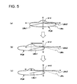
- FIGS. 5(a) through 5(c) are diagrams illustrating a change in a light distribution pattern in the failsafe control.
- the light distribution patterns shown in FIGS. 5(a) through 5(c) are light distribution patterns, which are formed on a virtual vertical screen positioned 25 m ahead of the vehicle, by light radiated from the vehicular illumination device 10 when the vehicle is traveling on a straight paved road having a single lane on one side (a two-lane road). As shown in FIGS.
- a center line LMc located in the middle
- a left side line LMs1 and a right side line LMs2 located on both sides of the center line LMc
- the left side line LMs1 extends in a lower left direction from a point H-V (an intersection of lines H-H and V-V), which is a vanishing point of a perspective projection
- the center line LMc and the right side line LMs2 extend in a lower right direction from the point H-V.
- the ECU 1 detects whether light distribution switching means, which includes the beam switching circuit 24, the beam switching mechanism 140, and the signal transmission path S4, is in an abnormal state or not (S10). If the light distribution switch means is not in an abnormal state (N in S10), the control flow is terminated.
- the ECU 1 determines whether the lamp unit 110 has been switched to the main beam state or the sub beam state (S12). If it is determined that the lamp unit 110 has been switched to the sub beam (N in S12), the control flow is terminated. This is because there is no risk of dazzling to oncoming vehicles in the sub beam state.
- FIG. 5(a) shows a main beam distribution pattern PLM.
- a part of the radiated light may radiate upwards or rightwards with respect to the horizontal direction, which can cause dazzling to the oncoming vehicles and the pedestrians.
- the ECU 1 controls the swivel drive circuit 22 to move the swivel mechanism 120, thereby deflecting the radiating direction of the lamp unit 110 in a direction opposite to the direction of the opposite lane, and fixing the radiating direction to that direction (swivel control: S14).
- FIG. 5(b) shows a light distribution pattern after the swivel control. As shown in FIG. 5(b) , in the case of, e.g., left-hand traffic, the radiating direction is deflected leftwards with respect to the straight traveling direction.
- FIG. 5(c) shows a light distribution pattern after the leveling control.
- a region located on the right side of the point H-V in the horizontal direction is removed from the main beam distribution pattern PLM, whereby dazzling to the oncoming vehicles and the pedestrians can be reduced.
- the lamp unit 110 since the lamp unit 110 is neither turned down nor turned off, reduction in visibility of the driver and reduction in visibility of the vehicle can be minimized.
- the deflection amount of the radiating direction of the lamp unit 110 in the above swivel control and the above leveling control is determined as appropriate according to the main beam distribution pattern. That is, the deflection amount of the radiating direction of the lamp unit 110 is determined so that the region located on the opposite-lane side with respect to the point H-V is away from the main beam distribution pattern. This can reduce dazzling to the oncoming vehicles and the pedestrians in a preferable manner.
- the left and right headlamps RHL, LHL are controlled simultaneously.
- normal AFS control may be performed on the headlamp in a normal state
- the dazzling reducing control described above may be performed only on the headlamp in an abnormal state.
- the above embodiment is structured so that the leveling control is performed after the swivel control.
- the order of performing these controls is not specifically limited to this.
- the swivel control may be performed after the leveling control, or the swivel control and the leveling control may be performed simultaneously.
- the swivel drive circuit 22, the leveling drive circuit 23, and the beam switch circuit 24 are shown as structures independent of the swivel mechanism 120, the leveling mechanism 130, and the beam switch mechanism 140, respectively.
- these circuits may be assembled integrally in the lamp bodies 101 of the headlamps RHL, LHL by a circuit board or the like, or may be assembled integrally as a part of each mechanism.
- the swivel mechanism 120 and the leveling mechanism 130 are not limited to the structure of the example embodiment, and the present invention may be applied to any mechanism capable of deflecting the radiating direction of the headlamp in the lateral direction and the vertical direction.
- the headlamp of the present invention is not limited to the structure including the projector-type lamp unit described in the embodiment, and may be similarly applied to a reflector-type lamp that reflects light emitted from a light source.
- the means for switching the beam between the main beam and the sub beam is not limited to the structure in which the beam is switched by driving the shade, and the present invention may also be applied to lamps that are structured to be turned on by switching a filament of a bulb as a light source.
- the ECU 1 deflects the radiating direction of the lamp unit 110 in the direction opposite to the opposite-lane direction as the swivel control of S14.
- the deflecting direction is not limited to the direction opposite to the opposite-lane direction, and the radiating direction may be deflected in either a left or right direction. This can also reduce dazzling to the oncoming vehicles and the pedestrians.
Abstract
Description
- The present invention relates to a vehicular illumination device, and more particularly, to a vehicle illumination device, which includes a lamp deflection angle control device for changing a radiating direction of lamp light according to a traveling state, such as an adaptive front-lighting system (hereinafter referred to as the "AFS"), in order to ensure traveling safety against system failures.
- Conventionally, a system described in Japanese Patent Application Laid-Open (Kokai) No.
JP-A-2006-182100 JP-A-2006-182100 - In the technique described in
JP-A-2006-182100 - However, performing such control may reduce the visibility of the driver, and also may reduce the visibility of the vehicle, by turning down or turning off the headlamps.
- The present invention has been developed in view of the above problems, and it is an object of the present invention to provide a vehicular illumination device, which is capable of reducing dazzling to oncoming vehicles and pedestrians while suppressing reduction in the visibility of a driver and reduction in the visibility of a vehicle, in case of AFS failures. The present invention presents an improvement over the vehicular illumination system described in
EP 2 813 051 , which discloses the features of the preamble ofclaim 1. - In order to solve the above problems, a vehicular illumination device according to an aspect of the present invention includes: swivel means for deflecting a radiating direction of a lamp included in a vehicle in a lateral direction; leveling means for deflecting the radiating direction of the lamp in a vertical direction; light distribution switching means for switching radiated light distribution of the lamp between a main beam and a sub beam; control means for controlling the swivel means, the leveling means, and the light distribution switching means according to a traveling state of the vehicle; and abnormal-state detecting means for detecting an abnormal state of the light distribution switching means in which the light distribution switching means fails to switch the radiated light distribution of the lamp from the main beam to the sub beam. When the abnormal state of the light distribution switching means is detected by the abnormal-state detecting means, the control means controls the swivel means to deflect the radiating direction of the lamp in the lateral direction, and controls the leveling means to deflect the radiating direction of the lamp in a downward direction.
- Since radiated light from the lamp is less likely to be radiated directly to oncoming vehicles and pedestrians, dazzling to the oncoming vehicles and the pedestrians can be reduced. Moreover, since the lamp is neither turned down nor turned off, reduction in the visibility of a driver and reduction in the visibility of the vehicle can be minimized.
- Another aspect of the present invention is also a vehicular illumination device. This vehicular illumination device includes: swivel means for deflecting a radiating direction of a lamp included in a vehicle in a lateral direction; leveling means for deflecting the radiating direction of the lamp in a vertical direction; light distribution switching means for switching radiated light distribution of the lamp between a main beam and a sub beam; control means for controlling the swivel means, the leveling means, and the light distribution switching means according to a traveling state of the vehicle; and abnormal-state detecting means for detecting an abnormal state of the light distribution switching means in which the light distribution switching means fails to switch the radiated light distribution of the lamp from the main beam to the sub beam. When the abnormal state of the light distribution switching means is detected by the abnormal-state detecting means, the control means controls the swivel means to deflect the radiating direction of the lamp in a direction opposite to an opposite-lane direction, and controls the leveling means to deflect the radiating direction of the lamp in a downward direction.
- In the present invention, a vehicular illumination device is provided, which is capable of reducing dazzling to oncoming vehicles and pedestrians while suppressing reduction in the visibility of a driver and reduction in the visibility of a vehicle, in case of AFS failures.
- Examples of the present invention will now be described in detail with reference to the accompanying drawings, in which:
-
FIG. 1 is a diagram showing the state where a vehicular illumination device of an embodiment of the present invention is applied to a vehicle; -
FIG. 2 is a diagram illustrating the structure of the vehicular illumination device; -
FIG. 3 is a partial exploded perspective view showing an inner structure of a headlamp; -
FIG. 4 is a flowchart illustrating failsafe control; and, -
FIGS. 5(a) through 5(c) are diagrams illustrating a change in a light distribution pattern in the failsafe control. -
FIG. 1 is a diagram showing the state where avehicular illumination device 10 of an embodiment of the present invention is applied to avehicle 100. Left and right headlamps LHL, RHL of thevehicle 100 are structured so that the radiating direction thereof can be deflected in a horizontal-lateral direction and a perpendicular-vertical direction, as described below. The deflection control in the horizontal-lateral direction is swivel control, and the deflection control in the perpendicular-vertical direction is leveling control. - As control means in the present invention, the
ECU 1 is capable of controlling deflecting operation of the left and right headlamps LHL, RHL, is capable of switching light distribution characteristics of each headlamp between a main beam and a sub beam, and also, is capable of adjusting brightness of each headlamp. The "main beam" as used herein includes: a so-called driving beam, which is also called a "high beam"; a motorway beam, which provides improved distance visibility for high-speed traveling; and a beam, which is a so-called "one-sided high beam," which provides a high beam on only one of the right and left sides in a plane vertical to an optical axis. The "sub beam" as used herein is a lower beam that does not cause dazzling to oncoming vehicles. - A
steering sensor 11 for detecting a rotation angle of a steering wheel SW of the vehicle, that is, a steering angle of the vehicle, avehicle speed sensor 12 for detecting a vehicle speed of the vehicle, and avehicle height sensor 13 for detecting a tilt angle of a longitudinal axis of the vehicle with respect to a horizontal direction are connected to theECU 1. A steering angle signal, a vehicle speed signal, and a tilt angle signal from the respective sensors are input to theECU 1. Note that, since the structures of thesteering sensor 11, thevehicle speed sensor 12, and thevehicle height sensor 13 are already known in the art, detailed description thereof will be omitted. Amain switch 14 for turning on the headlamps, and abeam switching switch 15 for switching light distribution between the main beam and the sub beam are also connected to theECU 1. -
FIG. 2 is a diagram illustrating the structure of thevehicular illumination device 10. InFIG. 2 , components corresponding to those inFIG. 1 are denoted by the same reference characters. Regarding the headlamps,FIG. 2 shows only one of the left and right headlamps. That is,FIG. 2 shows only the right headlamp RHL. The headlamp RHL includes alamp body 101, and thelamp body 101 is shaped like a container having an open front face, and atranslucent cover 102 is attached to the opening of the front face to form a lamp chamber 103 inside. A projector-type lamp unit 110 is disposed inside the lamp chamber 103. Thelamp unit 110 is structured so that the radiating direction of thelamp unit 110 can be deflected in a horizontal-lateral direction and a perpendicular-vertical direction by aswivel mechanism 120 and aleveling mechanism 130, respectively. Thelamp unit 110 is provided with abeam switching mechanism 140 for switching the beam between the main beam and the sub beam by driving ashade 141 provided inside of thelamp unit 110. -
FIG. 3 is a partial exploded perspective view showing an inner structure of the headlamp. Referring toFIGS. 2 and3 , a housing of thelamp unit 110 is formed by a rotationalellipsoidal reflector 111, aholder 112 connected to a front edge of thereflector 111, and alens 113 fixed to a front edge of theholder 112. A discharge bulb 114 as a light source is attached by asocket 115 that is attached to a bulb attachment hole provided on the rear face of thereflector 111. - The
beam switching mechanism 140 for limiting light emitted from the discharge bulb 114 to switch the light between the main beam and the sub beam is disposed inside theholder 112 of thelamp unit 110. Thebeam switching mechanism 140 includes theshade 141, which is rotatable in the vertical direction about a spindle 142 so that theshade 141 can advance to, and withdraw from, a position on an optical axis in front of the discharge bulb 114, and ashade driving portion 143 for turning theshade 141 in the perpendicular-vertical direction. - The
shade driving portion 143 is formed by: aspring 144 for urging theshade 141 to a sub beam position, which is a position where theshade 141 covers a part of a region in front of the discharge bulb 114; and a motor 145 having aplunger 146 for forcibly moving theshade 141, against the urging force of thespring 144, to a main beam position, which is a position to which theshade 141 is withdrawn from the position on the optical axis in front of the discharge bulb 114. Abeam switching circuit 24 is connected to the motor 145, and thebeam switching circuit 24 controls energization of the motor 145. In thebeam switching mechanism 140, during de-energization of the motor 145, theshade 141 is turned to a position on the optical axis in front of the discharge bulb 114 by the urging force of thespring 144, whereby emitted light from the discharge bulb 114 is partially blocked, and light distribution characteristics of radiated light from thelamp unit 110 is switched to a sub beam state. On the other hand, when thebeam switching circuit 24 energizes the motor 145, theshade 141 is turned downward against the urging force of thespring 144 so as to be withdrawn from the position on the optical axis in front of the discharge bulb 114, whereby the light distribution characteristics of radiated light from thelamp unit 110 is switched to a main beam state. - The
lamp unit 110 is disposed inside aframe 150, which is formed in a substantially U shape by bending. Thelamp unit 110 is supported so as to be able to turn in the horizontal direction aboutrotation spindles 116 provided in the upper and lower parts of theholder 112, in the state where thelamp unit 110 is vertically interposed between an upper plate 150U and a lower plate 150D of theframe 150, and in the state where thelamp unit 110 is inserted through anopening 154 provided in aback plate 150B of theframe 150. - Moreover, the
lamp unit 110 is capable of turning in the horizontal-lateral direction by theswivel mechanism 120. Theswivel mechanism 120 includes anactuator 121 as a turning drive source, and theactuator 121 is fixed to a lower surface of the lower plate 150D of theframe 150 by afixing screw 123. Arotation output shaft 122 protrudes from an upper surface of theactuator 121, and therotation output shaft 122 is connected to thelower rotation spindle 116 of thelamp unit 110. Theactuator 121 includes, as built-in elements, a motor, not shown in the drawing, a speed change mechanism for shifting a rotation output of the motor, and the like, and therotation output shaft 122 is rotated by rotation of the motor. Moreover, aswivel drive circuit 22 is connected to theactuator 121. As theswivel drive circuit 22 controls energization of theactuator 121, thelamp unit 110 is swung in a required angle range together with therotation spindles 116 by therotation output shaft 122, and the optical axis of thelamp unit 110, that is, the radiating direction thereof, is tilted laterally, whereby swivel control is performed. - The
frame 150 is supported by thelamp body 101 by aimingscrews 151 that screw in aimingnuts 152 provided at two positions on the upper side of theback plate 150B. Moreover, theframe 150 is connected to theleveling mechanism 130 in a ball bearing 153 provided in a part of the lower side of theback plate 150B. - The
leveling mechanism 130 has a levelingmotor 131 having aconnection rod 132 capable of advancing and withdrawing along a longitudinal direction of thelamp unit 110. The levelingmotor 131 is fixed to an outer surface of thelamp body 101, and a tip of theconnection rod 132 is fitted in theball bearing 153 of theframe 150. A leveling drive circuit 34 is connected to the levelingmotor 131, and the levelingdrive circuit 23 controls energization of the levelingmotor 131. In theleveling mechanism 130, as the levelingdrive circuit 23 drives the levelingmotor 131, theconnection rod 132 advances and withdraws in an axial direction, and theframe 150 connected to theconnection rod 132 is swung in a perpendicular direction by using the two aimingscrews 151 on the upper side as fulcrums, and the optical axis of thelamp unit 110 disposed inside theframe 150, that is, the radiating direction, is tilted vertically, whereby leveling control is performed. Note that by manually adjusting axial turning of the two aimingscrews 151, the two positions of the upper side of theframe 150 are moved independently in the longitudinal direction, thereby adjusting the tilt in the horizontal-lateral direction and the tilt in the perpendicular direction of theframe 150. It should be understood that this adjustment by the aiming screws 151 is performed to adjust the optical axis of thelamp unit 110 so that the optical axis of thelamp unit 110 faces toward a predetermined vertical direction when the vehicle takes a predetermined posture. - The
beam switching circuit 24, theswivel drive circuit 22, and the levelingdrive circuit 23 are connected to theECU 1 through signal transmission paths S4, S2, S3, respectively. TheECU 1 sends required control signals to thebeam switching circuit 24, theswivel drive circuit 22, and the levelingdrive circuit 23 via the signal transmission paths S4, S2, S3 so as to control the respective circuits, thereby controlling thebeam switching mechanism 140, theswivel mechanism 120, and theleveling mechanism 130. TheECU 1 thus performs the beam switch control, the swivel control, and the leveling control described above. - Moreover, the discharge bulb 114 of the
lamp unit 110 is connected to a ballast (booster)device 161 disposed on the inner bottom of thelamp body 101 by thesocket 115. Theballast device 161 is connected to theECU 1, and is connected also to alight adjusting circuit 21 connected to a power source (an on-board battery) not shown in the drawings. Theballast device 161 controls thelight adjusting circuit 21 via the signal transmission path S1 by theECU 1 to adjust the quantity of light that is radiated from thelamp unit 110. Note that, in order to transmit and receive signals between theECU 1 and eachcircuit ECU 1 and eachcircuit - Moreover, the
ECU 1 has a function to detect an abnormal state of thebeam switching circuit 24, thebeam switching mechanism 140, and the signal transmission path S4. TheECU 1 transmits a predetermined signal at a required timing to thebeam switching circuit 24 via the signal transmission path S4 that connects theECU 1 and thebeam switching circuit 24. By monitoring a response signal to this transmitted signal from thebeam switching circuit 24, theECU 1 can detect whether thebeam switching mechanism 140 connected to thebeam switching circuit 24 is operating normally or not, and whether the signal transmission path S4 between theECU 1 and thebeam switching circuit 24 is in a normal state or not. Then, when an abnormal state in thebeam switching circuit 24, thebeam switching mechanism 140, and the signal transmission path S4 is detected, theECU 1 performs failsafe control, which will be described below, to prevent dazzling to oncoming vehicles. - Next, normal control in the
vehicular illumination device 10 having the above structure will be described. When themain switch 14 is turned on, theECU 1 controls thelight adjusting circuit 21 to turn on the discharge bulb 114 of thelamp unit 110. When thebeam switching switch 15 is switched to the main beam side, theECU 1 controls thebeam switching circuit 24 to drive thebeam switching mechanism 140 so as to move theshade 141 to a position where theshade 141 is withdrawn from the position on the optical axis in front of the discharge bulb 114, thereby establishing a main beam state. When thebeam switching switch 15 is switched to the sub beam side, theECU 1 advances theshade 141 to the position on the optical axis in front of the discharge bulb 114 so as to block a part of light emitted from the discharge bulb 114, thereby establishing a sub beam state. - On the other hand, if the
vehicle 100 is steered during traveling, a steering angle signal from thesteering sensor 1 is input to theECU 1. At the same time, a vehicle speed signal and a vehicle height signal of thevehicle 100 are input from thevehicle speed sensor 12 and thevehicle height sensor 13 to theECU 1, respectively. TheECU 1 calculates an appropriate radiating direction of the headlamps RHL, LHL based on these signals, and controls theswivel drive circuit 22 and the levelingdrive circuit 23 based on the calculated radiating direction. Thus, the swivel control is performed in which theswivel drive circuit 22 drives theswivel mechanism 120 to tilt thelamp unit 110 in the lateral direction so that the radiating direction of thelamp unit 110, that is, the radiating direction of the headlamps RHL, LHL, becomes the desired lateral direction corresponding to the steering direction of thevehicle 100. Moreover, the leveling control is performed in which the levelingdrive circuit 23 drives theleveling mechanism 130 to tilt theframe 150 in the vertical direction so that the radiating direction of thelamp unit 110, that is, the radiating direction of the headlamps RHL, LHL, becomes the desired vertical direction corresponding to the traveling state of thevehicle 100. That is, AFS control is performed. - In such AFS control of the headlamps RHL, LHL, when an abnormal state occurs in the
beam switching circuit 24, thebeam switching mechanism 140, and the signal transmission path S4, switching between the main beam and the sub beam cannot be performed via theECU 1. If thelamp unit 110 has been switched to the main beam state when an abnormal state occurs, dazzling to oncoming vehicles may be caused. Thus, in thevehicular illumination device 10 of the present invention, theECU 1 performs failsafe control when theECU 1 detects an abnormal state in thebeam switching circuit 24, thebeam switching mechanism 140, and the signal transmission path S4. -
FIG. 4 is a flowchart illustrating the failsafe control. The flow shown inFIG. 4 is repeatedly executed at predetermined intervals. Moreover,FIGS. 5(a) through 5(c) are diagrams illustrating a change in a light distribution pattern in the failsafe control. The light distribution patterns shown inFIGS. 5(a) through 5(c) are light distribution patterns, which are formed on a virtual vertical screen positioned 25 m ahead of the vehicle, by light radiated from thevehicular illumination device 10 when the vehicle is traveling on a straight paved road having a single lane on one side (a two-lane road). As shown inFIGS. 5(a) through 5(c) , a center line LMc located in the middle, and a left side line LMs1 and a right side line LMs2 located on both sides of the center line LMc, are formed on a road surface ahead of the vehicle, as lane marks that define the vehicle traveling lanes. The left side line LMs1 extends in a lower left direction from a point H-V (an intersection of lines H-H and V-V), which is a vanishing point of a perspective projection, and the center line LMc and the right side line LMs2 extend in a lower right direction from the point H-V. - The
ECU 1 detects whether light distribution switching means, which includes thebeam switching circuit 24, thebeam switching mechanism 140, and the signal transmission path S4, is in an abnormal state or not (S10). If the light distribution switch means is not in an abnormal state (N in S10), the control flow is terminated. - If an abnormal state is detected in the light distribution means (Y in S10), the
ECU 1 determines whether thelamp unit 110 has been switched to the main beam state or the sub beam state (S12). If it is determined that thelamp unit 110 has been switched to the sub beam (N in S12), the control flow is terminated. This is because there is no risk of dazzling to oncoming vehicles in the sub beam state. - On the other hand, if it is determined that the
lamp unit 110 has been switched to the main beam (Y in S12), theECU 1 forcibly operates swivel means, which includes theswivel drive circuit 22 and theswivel mechanism 120, and leveling means, which includes the levelingdrive circuit 23 and theleveling mechanism 130, to reduce dazzling to oncoming vehicles and pedestrians.FIG. 5(a) shows a main beam distribution pattern PLM. In this case, as shown inFIG. 5(a) , a part of the radiated light may radiate upwards or rightwards with respect to the horizontal direction, which can cause dazzling to the oncoming vehicles and the pedestrians. - In order to reduce dazzling to the oncoming vehicles and the pedestrians, the
ECU 1 controls theswivel drive circuit 22 to move theswivel mechanism 120, thereby deflecting the radiating direction of thelamp unit 110 in a direction opposite to the direction of the opposite lane, and fixing the radiating direction to that direction (swivel control: S14).FIG. 5(b) shows a light distribution pattern after the swivel control. As shown inFIG. 5(b) , in the case of, e.g., left-hand traffic, the radiating direction is deflected leftwards with respect to the straight traveling direction. - Then, the
ECU 1 controls the levelingdrive circuit 23 to move theleveling mechanism 130, thereby deflecting the radiating direction of thelamp unit 110 downwards with respect to the horizontal direction, and fixing the radiating direction to that direction (leveling control: S16).FIG. 5(c) shows a light distribution pattern after the leveling control. As shown inFIG. 5(c) , by performing the swivel control and the leveling control, a region located on the right side of the point H-V in the horizontal direction is removed from the main beam distribution pattern PLM, whereby dazzling to the oncoming vehicles and the pedestrians can be reduced. Moreover, in the present embodiment, since thelamp unit 110 is neither turned down nor turned off, reduction in visibility of the driver and reduction in visibility of the vehicle can be minimized. - The deflection amount of the radiating direction of the
lamp unit 110 in the above swivel control and the above leveling control is determined as appropriate according to the main beam distribution pattern. That is, the deflection amount of the radiating direction of thelamp unit 110 is determined so that the region located on the opposite-lane side with respect to the point H-V is away from the main beam distribution pattern. This can reduce dazzling to the oncoming vehicles and the pedestrians in a preferable manner. - The present invention is described above based on the embodiment. It is to be understood by those skilled in the art that these embodiments are shown by way of example only, and various modifications can be made to combinations of the components and the processing processes, and such modifications fall within the scope of the present invention.
- For example, it is assumed in the above embodiment that the left and right headlamps RHL, LHL are controlled simultaneously. However, when an abnormal state is detected in the light distribution switching means in either of the left and right headlamps by detection of an abnormal state by the
ECU 1, normal AFS control may be performed on the headlamp in a normal state, and the dazzling reducing control described above may be performed only on the headlamp in an abnormal state. - Moreover, the above embodiment is structured so that the leveling control is performed after the swivel control. However, the order of performing these controls is not specifically limited to this. The swivel control may be performed after the leveling control, or the swivel control and the leveling control may be performed simultaneously.
- Moreover, in
FIG. 2 , theswivel drive circuit 22, the levelingdrive circuit 23, and thebeam switch circuit 24 are shown as structures independent of theswivel mechanism 120, theleveling mechanism 130, and thebeam switch mechanism 140, respectively. However, these circuits may be assembled integrally in thelamp bodies 101 of the headlamps RHL, LHL by a circuit board or the like, or may be assembled integrally as a part of each mechanism. Moreover, it is also to be understood that theswivel mechanism 120 and theleveling mechanism 130 are not limited to the structure of the example embodiment, and the present invention may be applied to any mechanism capable of deflecting the radiating direction of the headlamp in the lateral direction and the vertical direction. - Moreover, the headlamp of the present invention is not limited to the structure including the projector-type lamp unit described in the embodiment, and may be similarly applied to a reflector-type lamp that reflects light emitted from a light source. In this case, the means for switching the beam between the main beam and the sub beam is not limited to the structure in which the beam is switched by driving the shade, and the present invention may also be applied to lamps that are structured to be turned on by switching a filament of a bulb as a light source.
- Moreover, in the flowchart of
FIG. 4 , theECU 1 deflects the radiating direction of thelamp unit 110 in the direction opposite to the opposite-lane direction as the swivel control of S14. However, the deflecting direction is not limited to the direction opposite to the opposite-lane direction, and the radiating direction may be deflected in either a left or right direction. This can also reduce dazzling to the oncoming vehicles and the pedestrians.
Claims (2)
- A vehicular illumination device, comprising:swivel means for deflecting a radiating direction of a lamp included in a vehicle in a lateral direction;leveling means for deflecting the radiating direction of the lamp in a vertical direction;light distribution switching means for switching radiated light distribution of the lamp between a main beam and a sub beam;control means for controlling the swivel means, the leveling means, and the light distribution switching means according to a traveling state of the vehicle; andabnormal-state detecting means for detecting an abnormal state of the light distribution switching means in which the light distribution switching means fails to switch the radiated light distribution of the lamp from the main beam to the sub beam, whereinwhen the abnormal state of the light distribution switching means is detected by the abnormal-state detecting means, the control means
controls the leveling means to deflect the radiating direction of the lamp in a downward direction,characterized in that when the abnormal state of the light distribution switching means is detected by the abnormal-state detecting means, the control means additionally controls the swivel means to deflect the radiating direction of the lamp in the lateral direction. - A vehicular illumination device according to claim 1,
wherein when the abnormal state of the light distribution switching means is detected by the abnormal-state detecting means, the control means controls the swivel means to deflect the radiating direction of the lamp in a direction opposite to an opposite-lane direction, and controls the leveling means to deflect the radiating direction of the lamp in a downward direction.
Applications Claiming Priority (1)
| Application Number | Priority Date | Filing Date | Title |
|---|---|---|---|
| JP2008313654A JP2010137616A (en) | 2008-12-09 | 2008-12-09 | Lighting system for vehicle |
Publications (2)
| Publication Number | Publication Date |
|---|---|
| EP2196357A1 EP2196357A1 (en) | 2010-06-16 |
| EP2196357B1 true EP2196357B1 (en) | 2011-02-09 |
Family
ID=41716233
Family Applications (1)
| Application Number | Title | Priority Date | Filing Date |
|---|---|---|---|
| EP09177851A Revoked EP2196357B1 (en) | 2008-12-09 | 2009-12-03 | Vehicular illumination device |
Country Status (4)
| Country | Link |
|---|---|
| EP (1) | EP2196357B1 (en) |
| JP (1) | JP2010137616A (en) |
| AT (1) | ATE497898T1 (en) |
| DE (1) | DE602009000721D1 (en) |
Families Citing this family (5)
| Publication number | Priority date | Publication date | Assignee | Title |
|---|---|---|---|---|
| JP5454526B2 (en) * | 2011-07-25 | 2014-03-26 | トヨタ自動車株式会社 | Vehicle light distribution control device and method |
| CN106926770B (en) * | 2015-12-30 | 2019-06-14 | 中国移动通信集团公司 | A kind of lamp light control method and device |
| FR3056282B1 (en) * | 2016-09-19 | 2021-04-09 | Aml Systems | AUTOMOTIVE VEHICLE HEADLIGHT WITH STORAGE CODE FUNCTION. |
| CN110887005B (en) * | 2018-09-06 | 2023-07-14 | 法雷奥照明湖北技术中心有限公司 | Vehicle lamp and method for adjusting the same |
| FR3086900B1 (en) * | 2018-10-04 | 2022-09-09 | Renault Sas | MOTOR VEHICLE HEADLIGHT |
Family Cites Families (6)
| Publication number | Priority date | Publication date | Assignee | Title |
|---|---|---|---|---|
| DE10040573B4 (en) * | 2000-08-18 | 2014-05-08 | Automotive Lighting Reutlingen Gmbh | Headlamp for vehicles for generating a dipped beam and at least one light beam with a longer range |
| JP2003127760A (en) * | 2001-10-30 | 2003-05-08 | Koito Mfg Co Ltd | Headlamp for automobile |
| JP4094389B2 (en) * | 2002-09-10 | 2008-06-04 | 株式会社小糸製作所 | Vehicle headlamp device |
| JP4356935B2 (en) * | 2004-12-08 | 2009-11-04 | 株式会社小糸製作所 | Vehicle headlamp |
| JP2006182100A (en) * | 2004-12-27 | 2006-07-13 | Koito Mfg Co Ltd | Vehicular lighting system |
| JP4669434B2 (en) * | 2006-04-24 | 2011-04-13 | 株式会社小糸製作所 | Vehicle headlamp |
-
2008
- 2008-12-09 JP JP2008313654A patent/JP2010137616A/en active Pending
-
2009
- 2009-12-03 DE DE602009000721T patent/DE602009000721D1/en active Active
- 2009-12-03 AT AT09177851T patent/ATE497898T1/en not_active IP Right Cessation
- 2009-12-03 EP EP09177851A patent/EP2196357B1/en not_active Revoked
Also Published As
| Publication number | Publication date |
|---|---|
| DE602009000721D1 (en) | 2011-03-24 |
| JP2010137616A (en) | 2010-06-24 |
| ATE497898T1 (en) | 2011-02-15 |
| EP2196357A1 (en) | 2010-06-16 |
Similar Documents
| Publication | Publication Date | Title |
|---|---|---|
| EP2266838B1 (en) | Vehicle headlamp apparatus | |
| EP2295291B1 (en) | Vehicle headlight device | |
| US7815352B2 (en) | Vehicular headlamp | |
| US20070002571A1 (en) | Adaptive lighting system for motor vehicles | |
| EP2269869B1 (en) | Vehicle headlamp apparatus | |
| US9527431B2 (en) | Vehicle exterior mirror with adaptively activated forward lighting unit | |
| US20060139938A1 (en) | Vehicle lighting apparatus | |
| EP2154426B1 (en) | Vehicle headlamp apparatus | |
| JP5546326B2 (en) | Control device, vehicle lamp system, vehicle lamp | |
| US7195378B2 (en) | Vehicle lighting apparatus | |
| JP2003123514A (en) | Vehicular headlamp | |
| EP2196357B1 (en) | Vehicular illumination device | |
| JP2005029080A (en) | Vehicular lighting device | |
| US6478460B2 (en) | Headlamp of automobile | |
| EP2394851A2 (en) | Vehicle lighting system | |
| EP2100771B1 (en) | Vehicle headlight apparatus and method for controlling same | |
| JP2010040483A (en) | Vehicle headlight | |
| JP2000233684A (en) | Headlamp light distribution control device for automobile | |
| US8007119B2 (en) | Lamp system and lamp deflection control method | |
| US7150547B2 (en) | Turn signal and steering responsive adjustable lighting apparatus for vehicle | |
| US7014345B2 (en) | Auto-leveling system for vehicle headlamp | |
| JP5539784B2 (en) | VEHICLE LIGHT SYSTEM, CONTROL DEVICE, AND VEHICLE LIGHT | |
| US7153007B2 (en) | Vehicle lighting apparatus | |
| JP2004136864A (en) | Antiglare safety device for vehicle lamp | |
| KR20090114582A (en) | Dual head lamp system |
Legal Events
| Date | Code | Title | Description |
|---|---|---|---|
| PUAI | Public reference made under article 153(3) epc to a published international application that has entered the european phase |
Free format text: ORIGINAL CODE: 0009012 |
|
| 17P | Request for examination filed |
Effective date: 20091221 |
|
| AK | Designated contracting states |
Kind code of ref document: A1 Designated state(s): AT BE BG CH CY CZ DE DK EE ES FI FR GB GR HR HU IE IS IT LI LT LU LV MC MK MT NL NO PL PT RO SE SI SK SM TR |
|
| AX | Request for extension of the european patent |
Extension state: AL BA RS |
|
| GRAP | Despatch of communication of intention to grant a patent |
Free format text: ORIGINAL CODE: EPIDOSNIGR1 |
|
| RIC1 | Information provided on ipc code assigned before grant |
Ipc: B60Q 1/12 20060101ALI20100810BHEP Ipc: B60Q 1/10 20060101AFI20100810BHEP Ipc: B60Q 1/14 20060101ALI20100810BHEP |
|
| RIN1 | Information on inventor provided before grant (corrected) |
Inventor name: HORI, TAKASHIC/O KOITO MANUFACTURING CO., LTD. |
|
| GRAS | Grant fee paid |
Free format text: ORIGINAL CODE: EPIDOSNIGR3 |
|
| GRAA | (expected) grant |
Free format text: ORIGINAL CODE: 0009210 |
|
| AK | Designated contracting states |
Kind code of ref document: B1 Designated state(s): AT BE BG CH CY CZ DE DK EE ES FI FR GB GR HR HU IE IS IT LI LT LU LV MC MK MT NL NO PL PT RO SE SI SK SM TR |
|
| REG | Reference to a national code |
Ref country code: GB Ref legal event code: FG4D |
|
| REG | Reference to a national code |
Ref country code: CH Ref legal event code: EP |
|
| REG | Reference to a national code |
Ref country code: IE Ref legal event code: FG4D |
|
| REF | Corresponds to: |
Ref document number: 602009000721 Country of ref document: DE Date of ref document: 20110324 Kind code of ref document: P |
|
| REG | Reference to a national code |
Ref country code: DE Ref legal event code: R096 Ref document number: 602009000721 Country of ref document: DE Effective date: 20110324 |
|
| REG | Reference to a national code |
Ref country code: NL Ref legal event code: VDEP Effective date: 20110209 |
|
| LTIE | Lt: invalidation of european patent or patent extension |
Effective date: 20110209 |
|
| PG25 | Lapsed in a contracting state [announced via postgrant information from national office to epo] |
Ref country code: NO Free format text: LAPSE BECAUSE OF FAILURE TO SUBMIT A TRANSLATION OF THE DESCRIPTION OR TO PAY THE FEE WITHIN THE PRESCRIBED TIME-LIMIT Effective date: 20110509 Ref country code: LV Free format text: LAPSE BECAUSE OF FAILURE TO SUBMIT A TRANSLATION OF THE DESCRIPTION OR TO PAY THE FEE WITHIN THE PRESCRIBED TIME-LIMIT Effective date: 20110209 Ref country code: PT Free format text: LAPSE BECAUSE OF FAILURE TO SUBMIT A TRANSLATION OF THE DESCRIPTION OR TO PAY THE FEE WITHIN THE PRESCRIBED TIME-LIMIT Effective date: 20110609 Ref country code: ES Free format text: LAPSE BECAUSE OF FAILURE TO SUBMIT A TRANSLATION OF THE DESCRIPTION OR TO PAY THE FEE WITHIN THE PRESCRIBED TIME-LIMIT Effective date: 20110520 Ref country code: GR Free format text: LAPSE BECAUSE OF FAILURE TO SUBMIT A TRANSLATION OF THE DESCRIPTION OR TO PAY THE FEE WITHIN THE PRESCRIBED TIME-LIMIT Effective date: 20110510 Ref country code: SE Free format text: LAPSE BECAUSE OF FAILURE TO SUBMIT A TRANSLATION OF THE DESCRIPTION OR TO PAY THE FEE WITHIN THE PRESCRIBED TIME-LIMIT Effective date: 20110209 Ref country code: HR Free format text: LAPSE BECAUSE OF FAILURE TO SUBMIT A TRANSLATION OF THE DESCRIPTION OR TO PAY THE FEE WITHIN THE PRESCRIBED TIME-LIMIT Effective date: 20110209 Ref country code: LT Free format text: LAPSE BECAUSE OF FAILURE TO SUBMIT A TRANSLATION OF THE DESCRIPTION OR TO PAY THE FEE WITHIN THE PRESCRIBED TIME-LIMIT Effective date: 20110209 |
|
| PG25 | Lapsed in a contracting state [announced via postgrant information from national office to epo] |
Ref country code: NL Free format text: LAPSE BECAUSE OF FAILURE TO SUBMIT A TRANSLATION OF THE DESCRIPTION OR TO PAY THE FEE WITHIN THE PRESCRIBED TIME-LIMIT Effective date: 20110209 Ref country code: FI Free format text: LAPSE BECAUSE OF FAILURE TO SUBMIT A TRANSLATION OF THE DESCRIPTION OR TO PAY THE FEE WITHIN THE PRESCRIBED TIME-LIMIT Effective date: 20110209 Ref country code: CY Free format text: LAPSE BECAUSE OF FAILURE TO SUBMIT A TRANSLATION OF THE DESCRIPTION OR TO PAY THE FEE WITHIN THE PRESCRIBED TIME-LIMIT Effective date: 20110209 Ref country code: SI Free format text: LAPSE BECAUSE OF FAILURE TO SUBMIT A TRANSLATION OF THE DESCRIPTION OR TO PAY THE FEE WITHIN THE PRESCRIBED TIME-LIMIT Effective date: 20110209 Ref country code: PL Free format text: LAPSE BECAUSE OF FAILURE TO SUBMIT A TRANSLATION OF THE DESCRIPTION OR TO PAY THE FEE WITHIN THE PRESCRIBED TIME-LIMIT Effective date: 20110209 Ref country code: BE Free format text: LAPSE BECAUSE OF FAILURE TO SUBMIT A TRANSLATION OF THE DESCRIPTION OR TO PAY THE FEE WITHIN THE PRESCRIBED TIME-LIMIT Effective date: 20110209 Ref country code: BG Free format text: LAPSE BECAUSE OF FAILURE TO SUBMIT A TRANSLATION OF THE DESCRIPTION OR TO PAY THE FEE WITHIN THE PRESCRIBED TIME-LIMIT Effective date: 20110509 Ref country code: AT Free format text: LAPSE BECAUSE OF FAILURE TO SUBMIT A TRANSLATION OF THE DESCRIPTION OR TO PAY THE FEE WITHIN THE PRESCRIBED TIME-LIMIT Effective date: 20110209 |
|
| PG25 | Lapsed in a contracting state [announced via postgrant information from national office to epo] |
Ref country code: EE Free format text: LAPSE BECAUSE OF FAILURE TO SUBMIT A TRANSLATION OF THE DESCRIPTION OR TO PAY THE FEE WITHIN THE PRESCRIBED TIME-LIMIT Effective date: 20110209 Ref country code: DK Free format text: LAPSE BECAUSE OF FAILURE TO SUBMIT A TRANSLATION OF THE DESCRIPTION OR TO PAY THE FEE WITHIN THE PRESCRIBED TIME-LIMIT Effective date: 20110209 |
|
| PLBI | Opposition filed |
Free format text: ORIGINAL CODE: 0009260 |
|
| PG25 | Lapsed in a contracting state [announced via postgrant information from national office to epo] |
Ref country code: SK Free format text: LAPSE BECAUSE OF FAILURE TO SUBMIT A TRANSLATION OF THE DESCRIPTION OR TO PAY THE FEE WITHIN THE PRESCRIBED TIME-LIMIT Effective date: 20110209 Ref country code: CZ Free format text: LAPSE BECAUSE OF FAILURE TO SUBMIT A TRANSLATION OF THE DESCRIPTION OR TO PAY THE FEE WITHIN THE PRESCRIBED TIME-LIMIT Effective date: 20110209 Ref country code: RO Free format text: LAPSE BECAUSE OF FAILURE TO SUBMIT A TRANSLATION OF THE DESCRIPTION OR TO PAY THE FEE WITHIN THE PRESCRIBED TIME-LIMIT Effective date: 20110209 |
|
| 26 | Opposition filed |
Opponent name: HELLA KGAA HUECK & CO. Effective date: 20111109 |
|
| PLAX | Notice of opposition and request to file observation + time limit sent |
Free format text: ORIGINAL CODE: EPIDOSNOBS2 |
|
| REG | Reference to a national code |
Ref country code: DE Ref legal event code: R026 Ref document number: 602009000721 Country of ref document: DE Effective date: 20111109 |
|
| PLBB | Reply of patent proprietor to notice(s) of opposition received |
Free format text: ORIGINAL CODE: EPIDOSNOBS3 |
|
| PG25 | Lapsed in a contracting state [announced via postgrant information from national office to epo] |
Ref country code: IT Free format text: LAPSE BECAUSE OF FAILURE TO SUBMIT A TRANSLATION OF THE DESCRIPTION OR TO PAY THE FEE WITHIN THE PRESCRIBED TIME-LIMIT Effective date: 20110209 |
|
| PG25 | Lapsed in a contracting state [announced via postgrant information from national office to epo] |
Ref country code: MC Free format text: LAPSE BECAUSE OF NON-PAYMENT OF DUE FEES Effective date: 20111231 |
|
| REG | Reference to a national code |
Ref country code: IE Ref legal event code: MM4A |
|
| PG25 | Lapsed in a contracting state [announced via postgrant information from national office to epo] |
Ref country code: IE Free format text: LAPSE BECAUSE OF NON-PAYMENT OF DUE FEES Effective date: 20111203 |
|
| PG25 | Lapsed in a contracting state [announced via postgrant information from national office to epo] |
Ref country code: MK Free format text: LAPSE BECAUSE OF FAILURE TO SUBMIT A TRANSLATION OF THE DESCRIPTION OR TO PAY THE FEE WITHIN THE PRESCRIBED TIME-LIMIT Effective date: 20110209 Ref country code: MT Free format text: LAPSE BECAUSE OF FAILURE TO SUBMIT A TRANSLATION OF THE DESCRIPTION OR TO PAY THE FEE WITHIN THE PRESCRIBED TIME-LIMIT Effective date: 20110209 |
|
| PG25 | Lapsed in a contracting state [announced via postgrant information from national office to epo] |
Ref country code: SM Free format text: LAPSE BECAUSE OF FAILURE TO SUBMIT A TRANSLATION OF THE DESCRIPTION OR TO PAY THE FEE WITHIN THE PRESCRIBED TIME-LIMIT Effective date: 20110209 |
|
| PG25 | Lapsed in a contracting state [announced via postgrant information from national office to epo] |
Ref country code: LU Free format text: LAPSE BECAUSE OF NON-PAYMENT OF DUE FEES Effective date: 20111203 |
|
| PG25 | Lapsed in a contracting state [announced via postgrant information from national office to epo] |
Ref country code: IS Free format text: LAPSE BECAUSE OF FAILURE TO SUBMIT A TRANSLATION OF THE DESCRIPTION OR TO PAY THE FEE WITHIN THE PRESCRIBED TIME-LIMIT Effective date: 20110209 |
|
| PLAB | Opposition data, opponent's data or that of the opponent's representative modified |
Free format text: ORIGINAL CODE: 0009299OPPO |
|
| PG25 | Lapsed in a contracting state [announced via postgrant information from national office to epo] |
Ref country code: TR Free format text: LAPSE BECAUSE OF FAILURE TO SUBMIT A TRANSLATION OF THE DESCRIPTION OR TO PAY THE FEE WITHIN THE PRESCRIBED TIME-LIMIT Effective date: 20110209 |
|
| R26 | Opposition filed (corrected) |
Opponent name: HELLA KGAA HUECK & CO. Effective date: 20111109 |
|
| PG25 | Lapsed in a contracting state [announced via postgrant information from national office to epo] |
Ref country code: HU Free format text: LAPSE BECAUSE OF FAILURE TO SUBMIT A TRANSLATION OF THE DESCRIPTION OR TO PAY THE FEE WITHIN THE PRESCRIBED TIME-LIMIT Effective date: 20110209 |
|
| REG | Reference to a national code |
Ref country code: DE Ref legal event code: R103 Ref document number: 602009000721 Country of ref document: DE Ref country code: DE Ref legal event code: R064 Ref document number: 602009000721 Country of ref document: DE |
|
| RDAF | Communication despatched that patent is revoked |
Free format text: ORIGINAL CODE: EPIDOSNREV1 |
|
| PGFP | Annual fee paid to national office [announced via postgrant information from national office to epo] |
Ref country code: GB Payment date: 20131127 Year of fee payment: 5 Ref country code: DE Payment date: 20131127 Year of fee payment: 5 |
|
| PGFP | Annual fee paid to national office [announced via postgrant information from national office to epo] |
Ref country code: FR Payment date: 20131209 Year of fee payment: 5 |
|
| RDAG | Patent revoked |
Free format text: ORIGINAL CODE: 0009271 |
|
| STAA | Information on the status of an ep patent application or granted ep patent |
Free format text: STATUS: PATENT REVOKED |
|
| REG | Reference to a national code |
Ref country code: CH Ref legal event code: PLX |
|
| 27W | Patent revoked |
Effective date: 20131119 |
|
| GBPR | Gb: patent revoked under art. 102 of the ep convention designating the uk as contracting state |
Effective date: 20131119 |
|
| REG | Reference to a national code |
Ref country code: DE Ref legal event code: R107 Ref document number: 602009000721 Country of ref document: DE Effective date: 20140703 |
|
| PG25 | Lapsed in a contracting state [announced via postgrant information from national office to epo] |
Ref country code: LI Free format text: LAPSE BECAUSE OF THE APPLICANT RENOUNCES Effective date: 20110209 Ref country code: CH Free format text: LAPSE BECAUSE OF THE APPLICANT RENOUNCES Effective date: 20110209 |