EP1138549B1 - Halterung für einen Getränkebehälter - Google Patents
Halterung für einen Getränkebehälter Download PDFInfo
- Publication number
- EP1138549B1 EP1138549B1 EP01105976A EP01105976A EP1138549B1 EP 1138549 B1 EP1138549 B1 EP 1138549B1 EP 01105976 A EP01105976 A EP 01105976A EP 01105976 A EP01105976 A EP 01105976A EP 1138549 B1 EP1138549 B1 EP 1138549B1
- Authority
- EP
- European Patent Office
- Prior art keywords
- receiving space
- receptacle
- ashtray
- container
- beverage container
- Prior art date
- Legal status (The legal status is an assumption and is not a legal conclusion. Google has not performed a legal analysis and makes no representation as to the accuracy of the status listed.)
- Expired - Lifetime
Links
- 235000013361 beverage Nutrition 0.000 title abstract description 21
- 230000037431 insertion Effects 0.000 claims abstract 3
- 238000003780 insertion Methods 0.000 claims abstract 3
- 241000510164 Cumberlandia monodonta Species 0.000 description 1
- 230000005484 gravity Effects 0.000 description 1
- 230000002093 peripheral effect Effects 0.000 description 1
Images



Classifications
-
- B—PERFORMING OPERATIONS; TRANSPORTING
- B60—VEHICLES IN GENERAL
- B60N—SEATS SPECIALLY ADAPTED FOR VEHICLES; VEHICLE PASSENGER ACCOMMODATION NOT OTHERWISE PROVIDED FOR
- B60N3/00—Arrangements or adaptations of other passenger fittings, not otherwise provided for
- B60N3/10—Arrangements or adaptations of other passenger fittings, not otherwise provided for of receptacles for food or beverages, e.g. refrigerated
- B60N3/102—Arrangements or adaptations of other passenger fittings, not otherwise provided for of receptacles for food or beverages, e.g. refrigerated storable or foldable in a non-use position
-
- B—PERFORMING OPERATIONS; TRANSPORTING
- B60—VEHICLES IN GENERAL
- B60N—SEATS SPECIALLY ADAPTED FOR VEHICLES; VEHICLE PASSENGER ACCOMMODATION NOT OTHERWISE PROVIDED FOR
- B60N3/00—Arrangements or adaptations of other passenger fittings, not otherwise provided for
- B60N3/10—Arrangements or adaptations of other passenger fittings, not otherwise provided for of receptacles for food or beverages, e.g. refrigerated
- B60N3/105—Arrangements or adaptations of other passenger fittings, not otherwise provided for of receptacles for food or beverages, e.g. refrigerated for receptables of different size or shape
- B60N3/108—Arrangements or adaptations of other passenger fittings, not otherwise provided for of receptacles for food or beverages, e.g. refrigerated for receptables of different size or shape with resilient holding elements
Definitions
- the invention relates to a holder for a beverage container, such as a beverage can, a cup or a cup, with the features of the preamble of claim 1.
- brackets are known per se in an almost unmanageable variety of designs. (see eg the US-A-5 598 999 Patent)
- the invention has for its object to form a holder for a beverage container to save space accommodated.
- the holder according to the invention according to claim 1 has a receiving space for adjusting the beverage container.
- the receiving space may for example be a recess in a dashboard or a center console of a motor vehicle.
- a container is included, for example, an ashtray, a storage compartment or a spectacle case.
- This has the advantage that the receiving space for adjusting the beverage container when not in use for a beverage container to accommodate the container is available, the space occupied by the receiving space is thereby used twice.
- the holder according to the invention has a guide on which the container is guided out of the receiving space movable. If the container is moved out of the receiving space, a beverage container can be set in the receiving space.
- the guide for the container or the receptacle is designed as a telescopic guide.
- the container or the receptacle is guided with the telescopic guide, for example, upwards displaceable.
- the guide may have a pivot bearing to pivot the receiving space or the container to the side, so that the receiving space for adjusting the beverage container or the container for inserting or removing an object is accessible.
- the container is an ashtray.
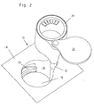
- the holder 10 according to the invention shown in FIGS. 1-3 is provided for setting a beverage container such as a beverage can 12 (FIG. 3), a cup or a cup.
- the bracket 10 is for example housed in a dashboard or a center console 14 of a motor vehicle, wherein the dashboard or the center console 14 are shown in the drawing as a square surface.
- the holder 10 has a receiving space 16 for adjusting the beverage container 12, wherein the receiving space 16 is formed as a substantially cylindrical recess of the center console 14.
- an approximately extending in the circumferential direction compensating flap 20 is mounted, the spring-loaded a piece far into the receiving space 16 pivoted into it.
- the compensating flap 20 serves to adapt the receiving space 16 to beverage containers of different diameters.
- the holder 10 has a telescopic guide 22, to which a container, in the illustrated embodiment, an ashtray 24 is attached.
- the ashtray 24 can be displaced from a position recessed in the receiving space 16 (FIG. 1) into a position moved upward out of the receiving space 16 (FIGS. 2 and 3).
- the lifting of the ashtray 24 from the receiving space 16 out is preferably carried out by a spring arranged in the telescopic guide 22, not visible in the drawing spring.
- the ashtray 24 is held by a locking device, for example a known push-push mechanism, which can be unlocked by brief pressure on the ashtray 24.
- the telescopic guide 22 has a pivot bearing, with which the ashtray 24 is pivotable in the position shown in Figures 2 and 3, opposite the receiving space 16 pivoted to the side.
- the receiving space 16 is freely accessible from above, so that a beverage container 12 can be adjusted into the receiving space 16 as shown in FIG.
- a lid 26 is pivotally mounted about a vertical pivot axis to the side. With the lid 26 of the ashtray 24 is closed. In the lowered into the receiving space 16 position of the ashtray 24 with the lid 26 at the same time as the ashtray 24 and the receiving space 16 can be closed. The lid 26 can also be pivoted in the lowered into the receiving space 16 position of the ashtray 24 to the side, so that the ashtray 24 is available even in the lowered position.
- FIGS. 4-7 In order to explain the second exemplary embodiment of a holder 10 according to the invention shown in FIGS. 4 to 7, identical reference numbers are used for FIGS. 1 to 3 with the same components as in FIGS.
- the illustrated in Figures 4-7 Holder 10 has a claw-shaped, circular receptacle 28 for adjusting a beverage container, for example a cup 30.
- the receptacle 28 In a basic position ( Figures 4 and 5), the receptacle 28 is recessed in an approximately cylindrical recess 32 of the dashboard or the center console 14 is arranged.
- the receptacle 28 surrounds a likewise cylindrical container, in the illustrated embodiment, an ashtray 24, which is arranged sunk in the recess 32 in the center console 14.
- the ashtray 24 is arranged fixedly in the recess 32 in the center console 14 and the receptacle 28 can be raised out of the recess 32 with a telescopic guide upward in the holder 10 according to the invention shown in FIGS. 4 to 7.
- the telescopic guide is covered in Figures 4-7 of the receptacle 28 and is therefore not visible.
- the telescopic guide comprises a pivot bearing, with which the receptacle 28 is pivotable to the side in the position shown in Figures 6 and 7, in which the ashtray 24 is accessible.
- the ashtray 24 has a lid 26 pivotable about a vertical axis, which closes the ashtray 24 in FIGS. 4, 6 and 7.
- the receptacle 28 has a compensating flap 20 which extends approximately in the circumferential direction of the receptacle 28 and spring-loaded pivoted into the receptacle 28 into it.
- the receptacle 28 has two bottom flaps 34, which are mounted with horizontal pivot shafts 36 pivotally in the receptacle 28.
- the bottom flaps 34 are pivoted from the ashtray 24 up in recesses 38 on the inside of the receptacle 28 into it.
Landscapes
- Engineering & Computer Science (AREA)
- Physics & Mathematics (AREA)
- Thermal Sciences (AREA)
- Transportation (AREA)
- Mechanical Engineering (AREA)
- Passenger Equipment (AREA)
- Filling Of Jars Or Cans And Processes For Cleaning And Sealing Jars (AREA)
- Vehicle Step Arrangements And Article Storage (AREA)
Description
- Die Erfindung betrifft eine Halterung für einen Getränkebehälter, wie beispielsweise eine Getränkedose, einen Becher oder eine Tasse, mit den Merkmalen des Oberbegriffs des Anspruchs 1.
- Derartige Halterungen sind in einer nahezu unüberschaubaren Vielzahl an Ausführungen an sich bekannt. (siehe z.B. die
US-A-5 598 999 Patentschrift) Der Erfindung liegt die Aufgabe zugrunde, eine Halterung für einen Getränkebehälter platzsparend unterbringbar auszubilden. - Diese Aufgabe wird erfindungsgemäß durch die Merkmale des Anspruchs 1 gelöst. Die erfindungsgemäße Halterung gemäß Anspruch 1 weist einen Aufnahmeraum zum Einstellen des Getränkebehälters auf. Der Aufnahmeraum kann beispielsweise eine Aussparung in einem Armaturenbrett oder einer Mittelkonsole eines Kraftwagens sein. Im Aufnahmeraum ist ein Behältnis aufgenommen, beispielsweise ein Aschenbecher, ein Ablagefach oder ein Brillenetui. Dies hat den Vorteil, dass der Aufnahmeraum zum Einstellen des Getränkebehälters bei Nichtnutzung für einen Getränkebehälter zur Unterbringung des Behältnisses nutzbar ist, der vom Aufnahmeraum eingenommene Bauraum wird dadurch doppelt genutzt. Um einen Getränkebehälter in den Aufnahmeraum einstellen zu können, weist die erfindungsgemäße Halterung eine Führung auf, an der das Behältnis aus dem Aufnahmeraum heraus bewegbar geführt ist. Ist das Behältnis aus dem Aufnahmeraum heraus bewegt, lässt sich ein Getränkebehälter in den Aufnahmeraum einstellen.
- Bei einer Ausgestaltung der Erfindung ist die Führung für das Behältnis bzw. die Aufnahme als Teleskopführung ausgebildet. Das Behältnis bzw. die Aufnahme ist mit der Teleskopführung beispielsweise nach oben verschieblich geführt. Zusätzlich kann die Führung eine Schwenklagerung aufweisen, um den Aufnahmeraum bzw. das Behältnis zur Seite schwenken zu können, damit der Aufnahmeraum zum Einstellen des Getränkebehälters bzw. das Behältnis zum Einlegen oder Entnehmen eines Gegenstandes zugänglich ist.
- Bei einer Ausgestaltung der Erfindung ist das Behältnis ein Aschenbecher.
- Die Erfindung wird nachfolgend anhand zweier in der Zeichnung dargestellter Ausführungsbeispiele näher erläutert. Es zeigen:
- Figuren 1 - 3
- ein erstes Ausführungsbeispiel der Erfindung in unterschiedlichen Stellungen; und
- Figuren 4 - 7
- ein zweites Ausführungsbeispiel der Erfindung in unterschiedlichen Stellungen.
- Die in Figuren 1 - 3 dargestellte, erfindungsgemäße Halterung 10 ist zum Einstellen eines Getränkebehälters wie beispielsweise einer Getränkedose 12 (Figur 3), eines Bechers oder einer Tasse vorgesehen. Die Halterung 10 ist beispielsweise in einem Armaturenbrett oder einer Mittelkonsole 14 eines Kraftwagens untergebracht, wobei das Armaturenbrett oder die Mittelkonsole 14 in der Zeichnung als quadratische Fläche dargestellt sind. Die Halterung 10 weist einen Aufnahmeraum 16 zum Einstellen des Getränkebehälters 12 auf, wobei der Aufnahmeraum 16 als im Wesentlichen zylinderförmige Vertiefung der Mittelkonsole 14 ausgebildet ist. In einer Umfangswand 18 des Aufnahmeraums 16 ist eine näherungsweise in Umfangsrichtung verlaufende Ausgleichsklappe 20 angebracht, die federbeaufschlagt ein Stück weit in den Aufnahmeraum 16 hinein verschwenkt. Die Ausgleichsklappe 20 dient der Anpassung des Aufnahmeraums 16 an Getränkebehälter unterschiedlichen Durchmessers.
- In einer seitlichen Erweiterung des Aufnahmeraums 16 weist die Halterung 10 eine Teleskopführung 22 auf, an der ein Behältnis, im dargestellten Ausführungsbeispiel ein Aschenbecher 24 angebracht ist. Mittels der Teleskopführung 22 lässt sich der Aschenbecher 24 aus einer im Aufnahmeraum 16 versenkten Stellung (Figur 1) in eine nach oben aus dem Aufnahmeraum 16 heraus bewegte Stellung verschieben (Figuren 2 und 3). Das Anheben des Aschenbechers 24 aus dem Aufnahmeraum 16 heraus erfolgt vorzugsweise federbetätigt von einer in der Teleskopführung 22 angeordneten, in der Zeichnung nicht sichtbaren Feder. In der im Aufnahmeraum 16 versenkten Stellung wird der Aschenbecher 24 durch eine Verriegelungseinrichtung, beispielsweise eine an sich bekannte Push-Push-Mechanik gehalten, die durch kurzen Druck auf den Aschenbecher 24 entriegelbar ist.
- Die Teleskopführung 22 weist eine Schwenklagerung auf, mit der der Aschenbecher 24 in die in Figuren 2 und 3 dargestellte, gegenüber dem Aufnahmeraum 16 zur Seite verschwenkte Stellung schwenkbar ist. Durch das seitliche Verschwenken des aus dem Aufnahmeraum 16 nach oben heraus angehobenen Aschenbechers 24 wird der Aufnahmeraum 16 frei von oben zugänglich, so dass ein Getränkebehälter 12 wie in Figur 3 dargestellt in den Aufnahmeraum 16 einstellbar ist.
- An einer Oberseite des Aschenbechers 14 ist ein Deckel 26 um eine vertikale Schwenkachse zur Seite schwenkbar angebracht. Mit dem Deckel 26 ist der Aschenbecher 24 verschließbar. In der in den Aufnahmeraum 16 abgesenkten Stellung des Aschenbechers 24 ist mit dem Deckel 26 zugleich mit dem Aschenbecher 24 auch der Aufnahmeraum 16 verschließbar. Der Deckel 26 lässt sich auch in der in den Aufnahmeraum 16 abgesenkten Stellung des Aschenbechers 24 zur Seite schwenken, so dass der Aschenbecher 24 auch in der abgesenkten Stellung nutzbar ist.
- Zur Erläuterung des zweiten, in Figuren 4 - 7 dargestellten Ausführungsbeispiels einer erfindungsgemäßen Halterung 10 werden für mit Figuren 1 - 3 gleiche Bauteile mit Figuren 1 - 3 übereinstimmende Bezugszahlen verwendet. Die in Figuren 4 - 7 dargestellte Halterung 10 weist eine klauenförmige, kreisrunde Aufnahme 28 zum Einstellen eines Getränkebehälters, beispielsweise einer Tasse 30 auf. In einer Grundstellung (Figuren 4 und 5) ist die Aufnahme 28 versenkt in einer näherungsweise zylindrischen Vertiefung 32 des Armaturenbretts oder der Mittelkonsole 14 angeordnet. Die Aufnahme 28 umgreift ein ebenfalls zylinderförmiges Behältnis, im dargestellten Ausführungsbeispiel einen Aschenbecher 24, der versenkt in der Ausnehmung 32 in der Mittelkonsole 14 angeordnet ist. Im Unterschied zu Figuren 1 - 3 ist bei der in Figuren 4 - 7 dargestellten, erfindungsgemäßen Halterung 10 der Aschenbecher 24 feststehend in der Ausnehmung 32 in der Mittelkonsole 14 angeordnet und die Aufnahme 28 ist mit einer Teleskopführung nach oben aus der Ausnehmung 32 heraus anhebbar. Die Teleskopführung wird in Figuren 4 - 7 von der Aufnahme 28 verdeckt und ist deswegen nicht sichtbar. Die Teleskopführung umfasst eine Schwenklagerung, mit der die Aufnahme 28 zur Seite in die in Figuren 6 und 7 dargestellte Stellung schwenkbar ist, in der der Aschenbecher 24 zugänglich ist. Der Aschenbecher 24 weist einen um eine vertikale Achse schwenkbaren Deckel 26 auf, der in Figuren 4, 6 und 7 den Aschenbecher 24 verschließt.
- Die Aufnahme 28 weist eine Ausgleichsklappe 20 auf, die näherungsweise in Umfangsrichtung der Aufnahme 28 verläuft und federbeaufschlagt in die Aufnahme 28 hinein verschwenkt. Zum Abstellen des Getränkebehälters 30 weist die Aufnahme 28 zwei Bodenklappen 34 auf, die mit horizontalen Schwenkwellen 36 schwenkbar in der Aufnahme 28 gelagert sind. Beim Absenken der Aufnahme 28 in die Ausnehmung 32 der Mittelkonsole 14 werden die Bodenklappen 34 vom Aschenbecher 24 nach oben in Ausnehmungen 38 an der Innenseite der Aufnahme 28 hinein verschwenkt. Beim Anheben der Aufnahme 28 aus der Ausnehmung 32 der Mittelkonsole 14 heraus schwenken die Bodenklappen 34 durch Schwerkraft oder torsionsfederbetätigt in die in Figur 6 dargestellte horizontale Stützstellung.
Claims (6)
- Halterung für einen Getränkebehälter, mit einem Aufnahmeraum (16) zum Einstellen des Getränkebehälters, wobei in dem Aufnahmeraum (16) ein Behältnis (24) aufgenommen ist, das eine Führung (22) aufweist, an der es aus dem Aufnahmeraum (16) heraus bewegbar ist, und wobei die Führung (22) als Teleskopführung ausgebildet ist und eine Schwenklagerung aufweist, mit der das Behältnis (24) zur Seite schwenkbar geführt ist, dadurch gekennzeichnet, dass das Behältnis (24) in einer in den Aufnahmeraum (16) versenkten Stellung nutzbar ist.
- Halterung nach Anspruch 1, dadurch gekennzeichnet, dass das Behältnis (24) in einer aus dem Aufnahmeraum (16) heraus bewegten Stellung nutzbar ist.
- Halterung nach Anspruch 1, dadurch gekennzeichnet, dass das Behältnis (24) ein Aschenbecher ist.
- Halterung nach Anspruch 1, dadurch gekennzeichnet, dass die Halterung (10) einen Deckel (26) aufweist.
- Mittelkonsole eines Kraftwagens mit einer Halterung (10) für einen Getränkebehälter nach Anspruch 1.
- Mittelkonsole nach Anspruch 5, dadurch gekennzeichnet, dass der Aufnahmeraum (16) als im Wesentlichen zylinderförmige Vertiefung der Mittelkonsole (14) ausgebildet ist.
Applications Claiming Priority (2)
| Application Number | Priority Date | Filing Date | Title |
|---|---|---|---|
| DE10015197A DE10015197A1 (de) | 2000-03-27 | 2000-03-27 | Halterung für einen Getränkebehälter |
| DE10015197 | 2000-03-27 |
Publications (3)
| Publication Number | Publication Date |
|---|---|
| EP1138549A2 EP1138549A2 (de) | 2001-10-04 |
| EP1138549A3 EP1138549A3 (de) | 2004-01-28 |
| EP1138549B1 true EP1138549B1 (de) | 2007-06-13 |
Family
ID=7636576
Family Applications (1)
| Application Number | Title | Priority Date | Filing Date |
|---|---|---|---|
| EP01105976A Expired - Lifetime EP1138549B1 (de) | 2000-03-27 | 2001-03-10 | Halterung für einen Getränkebehälter |
Country Status (4)
| Country | Link |
|---|---|
| US (1) | US20010023872A1 (de) |
| EP (1) | EP1138549B1 (de) |
| AT (1) | ATE364527T1 (de) |
| DE (2) | DE10015197A1 (de) |
Families Citing this family (12)
| Publication number | Priority date | Publication date | Assignee | Title |
|---|---|---|---|---|
| DE20216674U1 (de) * | 2002-10-29 | 2003-03-13 | TRW Automotive Electronics & Components GmbH & Co.KG, 67677 Enkenbach-Alsenborn | Getränkehalter |
| DE20218745U1 (de) | 2002-12-04 | 2004-04-08 | Fischer Automotive Systems Gmbh | Halter für einen Getränkebehälter |
| DE102004015347A1 (de) | 2004-03-30 | 2005-10-20 | Porsche Ag | Halteeinrichtung für einen Nahrungsmittel- und/oder Getränkebehälter und Kraftfahrzeug mit einer derartigen Halteeinrichtung |
| DE102004017419A1 (de) * | 2004-04-08 | 2005-10-27 | Fischer Automotive Systems Gmbh | Getränkehalter |
| DE102004034127A1 (de) * | 2004-07-15 | 2006-02-02 | Audi Ag | Becherhalter für Kraftfahrzeuge |
| DE102004050286B4 (de) | 2004-10-15 | 2020-03-26 | Fischer Automotive Systems Gmbh & Co. Kg | Halter für einen Getränkebehälter zum Einbau in einem Kraftwagen |
| FR2927514B1 (fr) * | 2008-02-20 | 2010-03-26 | Roland Vlaemynck Tisseur | Support equipe de conteneur amovible et table equipee d'un tel support. |
| DE102008024695A1 (de) * | 2008-05-21 | 2009-11-26 | Daimler Ag | Haltevorrichtung für Staugut |
| DE102008059252A1 (de) * | 2008-11-27 | 2010-06-02 | GM Global Technology Operations, Inc., Detroit | Kraftfahrzeug mit Konsole, Konsole mit Gefäßhaltevorrichtung und Gefäßhaltevorrichtung |
| DE102010016574A1 (de) * | 2010-04-22 | 2011-10-27 | Fischer Automotive Systems Gmbh & Co. Kg | Getränkehalter |
| DE102015210979B4 (de) * | 2015-06-15 | 2020-02-06 | Bos Gmbh & Co. Kg | Behältnisaufnahmevorrichtung für einen Fahrzeuginnenraum |
| DE102016106060A1 (de) | 2016-04-04 | 2017-10-05 | Dr. Schneider Kunststoffwerke Gmbh | Aufbewahrungssystem |
Family Cites Families (7)
| Publication number | Priority date | Publication date | Assignee | Title |
|---|---|---|---|---|
| DE4022193A1 (de) * | 1990-07-12 | 1992-01-16 | Bayerische Motoren Werke Ag | Vorrichtung zum halten eines getraenkebehaelters oder dergleichen, insbesondere in einem kraftfahrzeug |
| DE4315584A1 (de) * | 1993-05-11 | 1995-01-12 | Happich Gmbh Gebr | Ascher für Fahrzeuge |
| US5330146A (en) * | 1993-12-07 | 1994-07-19 | Prince Corporation | Container holder |
| US5505516A (en) * | 1994-03-15 | 1996-04-09 | Prince Corporation | Compact container holder |
| US5489054A (en) * | 1994-08-17 | 1996-02-06 | Atlantic Automotive Components, Inc. | Extendible vehicle tray method and apparatus |
| DE4429515C1 (de) * | 1994-08-19 | 1995-11-16 | Fischer Artur Werke Gmbh | Vorrichtung zum Halten von zwei Getränkebehältnissen in der Mittelkonsole eines Kraftfahrzeugs |
| DE10007594A1 (de) * | 2000-02-18 | 2001-08-23 | Fischer Artur Werke Gmbh | Halterung für einen Getränkebehälter |
-
2000
- 2000-03-27 DE DE10015197A patent/DE10015197A1/de not_active Withdrawn
-
2001
- 2001-03-10 DE DE50112615T patent/DE50112615D1/de not_active Expired - Lifetime
- 2001-03-10 AT AT01105976T patent/ATE364527T1/de not_active IP Right Cessation
- 2001-03-10 EP EP01105976A patent/EP1138549B1/de not_active Expired - Lifetime
- 2001-03-26 US US09/817,726 patent/US20010023872A1/en not_active Abandoned
Also Published As
| Publication number | Publication date |
|---|---|
| ATE364527T1 (de) | 2007-07-15 |
| EP1138549A3 (de) | 2004-01-28 |
| US20010023872A1 (en) | 2001-09-27 |
| DE10015197A1 (de) | 2001-10-04 |
| DE50112615D1 (de) | 2007-07-26 |
| EP1138549A2 (de) | 2001-10-04 |
Similar Documents
| Publication | Publication Date | Title |
|---|---|---|
| EP1380466B1 (de) | Halter für einen Getränkebehälter | |
| EP1255662B1 (de) | Halterung für getränkebehälter | |
| EP3743314B1 (de) | Anordnung zur halterung eines mobilen endgerätes sowie fahrzeug mit einer derartigen halterungsanordnung | |
| EP1138549A2 (de) | Halterung für einen Getränkebehälter | |
| EP2726326B1 (de) | Kraftfahrzeug | |
| DE102014218412B4 (de) | Ablagefach mit Halterung | |
| EP0624490B1 (de) | Ascher für Fahrzeuge | |
| DE10148189A1 (de) | Halter für einen Getränkebehälter | |
| EP1181169B1 (de) | Halter für einen getränkebehälter | |
| EP1369298B1 (de) | Halter für einen Getränkebehälter | |
| DE102016119355B4 (de) | Ablagefach, umfassend ein faltbares Halteelement | |
| DE10112649A1 (de) | In ein Kraftfahrzeug einbaubarer Becherhalter | |
| DE102009058389B4 (de) | Kraftfahrzeug | |
| DE19749366B4 (de) | Vorrichtung zum Haltern von Getränkebehältnissen | |
| DE4228848C1 (de) | Haltevorrichtung für Getränkeflaschen an einem Fahrzeugsitz mit Armlehne | |
| DE10138292B4 (de) | Konsole mit Getränkehaltern mit einem Schubladenprinzip | |
| WO2003080450A2 (de) | Halter für einen getränkebehälter | |
| DE19543925C1 (de) | Multifunktionales Servicefach für Fahrzeuge | |
| DE10227646B3 (de) | Cupholderanordnung für Fahrzeuge | |
| EP1103416B1 (de) | Halter für einen Getränkebehälter in einem Kraftwagen | |
| EP1556281B1 (de) | Getraenkehalter | |
| EP4344954A1 (de) | Konsolenanordnung für ein fahrzeug | |
| DE102007029458B4 (de) | Mittelkonsole zum Einbau in einem Kraftfahrzeug-Innenraum mit einem Innenraum zur Aufnahme von Gegenständen | |
| DE102018103091A1 (de) | Aufbewahrungseinrichtung | |
| EP1447267B1 (de) | Halter für einen Getränkebehälter |
Legal Events
| Date | Code | Title | Description |
|---|---|---|---|
| PUAI | Public reference made under article 153(3) epc to a published international application that has entered the european phase |
Free format text: ORIGINAL CODE: 0009012 |
|
| AK | Designated contracting states |
Kind code of ref document: A2 Designated state(s): AT BE CH CY DE DK ES FI FR GB GR IE IT LI LU MC NL PT SE TR |
|
| AX | Request for extension of the european patent |
Free format text: AL;LT;LV;MK;RO;SI |
|
| PUAL | Search report despatched |
Free format text: ORIGINAL CODE: 0009013 |
|
| AK | Designated contracting states |
Kind code of ref document: A3 Designated state(s): AT BE CH CY DE DK ES FI FR GB GR IE IT LI LU MC NL PT SE TR |
|
| AX | Request for extension of the european patent |
Extension state: AL LT LV MK RO SI |
|
| 17P | Request for examination filed |
Effective date: 20040513 |
|
| AKX | Designation fees paid |
Designated state(s): AT BE CH CY DE DK ES FI FR GB GR IE IT LI LU MC NL PT SE TR |
|
| GRAP | Despatch of communication of intention to grant a patent |
Free format text: ORIGINAL CODE: EPIDOSNIGR1 |
|
| GRAS | Grant fee paid |
Free format text: ORIGINAL CODE: EPIDOSNIGR3 |
|
| GRAA | (expected) grant |
Free format text: ORIGINAL CODE: 0009210 |
|
| AK | Designated contracting states |
Kind code of ref document: B1 Designated state(s): AT BE CH CY DE DK ES FI FR GB GR IE IT LI LU MC NL PT SE TR |
|
| REG | Reference to a national code |
Ref country code: GB Ref legal event code: FG4D Free format text: NOT ENGLISH |
|
| REG | Reference to a national code |
Ref country code: CH Ref legal event code: EP |
|
| REG | Reference to a national code |
Ref country code: IE Ref legal event code: FG4D Free format text: LANGUAGE OF EP DOCUMENT: GERMAN |
|
| REF | Corresponds to: |
Ref document number: 50112615 Country of ref document: DE Date of ref document: 20070726 Kind code of ref document: P |
|
| PG25 | Lapsed in a contracting state [announced via postgrant information from national office to epo] |
Ref country code: SE Free format text: LAPSE BECAUSE OF FAILURE TO SUBMIT A TRANSLATION OF THE DESCRIPTION OR TO PAY THE FEE WITHIN THE PRESCRIBED TIME-LIMIT Effective date: 20070913 |
|
| NLV1 | Nl: lapsed or annulled due to failure to fulfill the requirements of art. 29p and 29m of the patents act | ||
| GBV | Gb: ep patent (uk) treated as always having been void in accordance with gb section 77(7)/1977 [no translation filed] |
Effective date: 20070613 |
|
| REG | Reference to a national code |
Ref country code: IE Ref legal event code: FD4D |
|
| PG25 | Lapsed in a contracting state [announced via postgrant information from national office to epo] |
Ref country code: IE Free format text: LAPSE BECAUSE OF FAILURE TO SUBMIT A TRANSLATION OF THE DESCRIPTION OR TO PAY THE FEE WITHIN THE PRESCRIBED TIME-LIMIT Effective date: 20070613 Ref country code: NL Free format text: LAPSE BECAUSE OF FAILURE TO SUBMIT A TRANSLATION OF THE DESCRIPTION OR TO PAY THE FEE WITHIN THE PRESCRIBED TIME-LIMIT Effective date: 20070613 Ref country code: ES Free format text: LAPSE BECAUSE OF FAILURE TO SUBMIT A TRANSLATION OF THE DESCRIPTION OR TO PAY THE FEE WITHIN THE PRESCRIBED TIME-LIMIT Effective date: 20070924 Ref country code: PT Free format text: LAPSE BECAUSE OF FAILURE TO SUBMIT A TRANSLATION OF THE DESCRIPTION OR TO PAY THE FEE WITHIN THE PRESCRIBED TIME-LIMIT Effective date: 20071113 |
|
| EN | Fr: translation not filed | ||
| PLBE | No opposition filed within time limit |
Free format text: ORIGINAL CODE: 0009261 |
|
| STAA | Information on the status of an ep patent application or granted ep patent |
Free format text: STATUS: NO OPPOSITION FILED WITHIN TIME LIMIT |
|
| PG25 | Lapsed in a contracting state [announced via postgrant information from national office to epo] |
Ref country code: DK Free format text: LAPSE BECAUSE OF FAILURE TO SUBMIT A TRANSLATION OF THE DESCRIPTION OR TO PAY THE FEE WITHIN THE PRESCRIBED TIME-LIMIT Effective date: 20070613 Ref country code: GR Free format text: LAPSE BECAUSE OF FAILURE TO SUBMIT A TRANSLATION OF THE DESCRIPTION OR TO PAY THE FEE WITHIN THE PRESCRIBED TIME-LIMIT Effective date: 20070914 Ref country code: IT Free format text: LAPSE BECAUSE OF FAILURE TO SUBMIT A TRANSLATION OF THE DESCRIPTION OR TO PAY THE FEE WITHIN THE PRESCRIBED TIME-LIMIT Effective date: 20070613 Ref country code: GB Free format text: LAPSE BECAUSE OF FAILURE TO SUBMIT A TRANSLATION OF THE DESCRIPTION OR TO PAY THE FEE WITHIN THE PRESCRIBED TIME-LIMIT Effective date: 20070613 |
|
| 26N | No opposition filed |
Effective date: 20080314 |
|
| PG25 | Lapsed in a contracting state [announced via postgrant information from national office to epo] |
Ref country code: FR Free format text: LAPSE BECAUSE OF FAILURE TO SUBMIT A TRANSLATION OF THE DESCRIPTION OR TO PAY THE FEE WITHIN THE PRESCRIBED TIME-LIMIT Effective date: 20080208 |
|
| BERE | Be: lapsed |
Owner name: FISCHERWERKE ARTUR FISCHER G.M.B.H. & CO. KG Effective date: 20080331 |
|
| PG25 | Lapsed in a contracting state [announced via postgrant information from national office to epo] |
Ref country code: MC Free format text: LAPSE BECAUSE OF NON-PAYMENT OF DUE FEES Effective date: 20080331 |
|
| REG | Reference to a national code |
Ref country code: CH Ref legal event code: PL |
|
| PG25 | Lapsed in a contracting state [announced via postgrant information from national office to epo] |
Ref country code: LI Free format text: LAPSE BECAUSE OF NON-PAYMENT OF DUE FEES Effective date: 20080331 Ref country code: CH Free format text: LAPSE BECAUSE OF NON-PAYMENT OF DUE FEES Effective date: 20080331 |
|
| PG25 | Lapsed in a contracting state [announced via postgrant information from national office to epo] |
Ref country code: FI Free format text: LAPSE BECAUSE OF FAILURE TO SUBMIT A TRANSLATION OF THE DESCRIPTION OR TO PAY THE FEE WITHIN THE PRESCRIBED TIME-LIMIT Effective date: 20070613 Ref country code: BE Free format text: LAPSE BECAUSE OF NON-PAYMENT OF DUE FEES Effective date: 20080331 |
|
| PG25 | Lapsed in a contracting state [announced via postgrant information from national office to epo] |
Ref country code: CY Free format text: LAPSE BECAUSE OF FAILURE TO SUBMIT A TRANSLATION OF THE DESCRIPTION OR TO PAY THE FEE WITHIN THE PRESCRIBED TIME-LIMIT Effective date: 20070613 |
|
| PG25 | Lapsed in a contracting state [announced via postgrant information from national office to epo] |
Ref country code: AT Free format text: LAPSE BECAUSE OF NON-PAYMENT OF DUE FEES Effective date: 20080310 |
|
| PG25 | Lapsed in a contracting state [announced via postgrant information from national office to epo] |
Ref country code: LU Free format text: LAPSE BECAUSE OF NON-PAYMENT OF DUE FEES Effective date: 20080310 |
|
| PG25 | Lapsed in a contracting state [announced via postgrant information from national office to epo] |
Ref country code: TR Free format text: LAPSE BECAUSE OF FAILURE TO SUBMIT A TRANSLATION OF THE DESCRIPTION OR TO PAY THE FEE WITHIN THE PRESCRIBED TIME-LIMIT Effective date: 20070613 |
|
| PGFP | Annual fee paid to national office [announced via postgrant information from national office to epo] |
Ref country code: DE Payment date: 20120109 Year of fee payment: 12 |
|
| REG | Reference to a national code |
Ref country code: DE Ref legal event code: R119 Ref document number: 50112615 Country of ref document: DE Effective date: 20131001 |
|
| PG25 | Lapsed in a contracting state [announced via postgrant information from national office to epo] |
Ref country code: DE Free format text: LAPSE BECAUSE OF NON-PAYMENT OF DUE FEES Effective date: 20131001 |