EP1138416A2 - Gear and shaft and forming method thereof - Google Patents
Gear and shaft and forming method thereof Download PDFInfo
- Publication number
- EP1138416A2 EP1138416A2 EP01302888A EP01302888A EP1138416A2 EP 1138416 A2 EP1138416 A2 EP 1138416A2 EP 01302888 A EP01302888 A EP 01302888A EP 01302888 A EP01302888 A EP 01302888A EP 1138416 A2 EP1138416 A2 EP 1138416A2
- Authority
- EP
- European Patent Office
- Prior art keywords
- shaft
- tubular
- teeth
- forming
- flange
- Prior art date
- Legal status (The legal status is an assumption and is not a legal conclusion. Google has not performed a legal analysis and makes no representation as to the accuracy of the status listed.)
- Granted
Links
Images


Classifications
-
- B—PERFORMING OPERATIONS; TRANSPORTING
- B21—MECHANICAL METAL-WORKING WITHOUT ESSENTIALLY REMOVING MATERIAL; PUNCHING METAL
- B21K—MAKING FORGED OR PRESSED METAL PRODUCTS, e.g. HORSE-SHOES, RIVETS, BOLTS OR WHEELS
- B21K1/00—Making machine elements
- B21K1/28—Making machine elements wheels; discs
- B21K1/30—Making machine elements wheels; discs with gear-teeth
-
- B—PERFORMING OPERATIONS; TRANSPORTING
- B21—MECHANICAL METAL-WORKING WITHOUT ESSENTIALLY REMOVING MATERIAL; PUNCHING METAL
- B21K—MAKING FORGED OR PRESSED METAL PRODUCTS, e.g. HORSE-SHOES, RIVETS, BOLTS OR WHEELS
- B21K1/00—Making machine elements
- B21K1/06—Making machine elements axles or shafts
- B21K1/063—Making machine elements axles or shafts hollow
-
- B—PERFORMING OPERATIONS; TRANSPORTING
- B21—MECHANICAL METAL-WORKING WITHOUT ESSENTIALLY REMOVING MATERIAL; PUNCHING METAL
- B21K—MAKING FORGED OR PRESSED METAL PRODUCTS, e.g. HORSE-SHOES, RIVETS, BOLTS OR WHEELS
- B21K1/00—Making machine elements
- B21K1/06—Making machine elements axles or shafts
- B21K1/066—Making machine elements axles or shafts splined
-
- B—PERFORMING OPERATIONS; TRANSPORTING
- B21—MECHANICAL METAL-WORKING WITHOUT ESSENTIALLY REMOVING MATERIAL; PUNCHING METAL
- B21K—MAKING FORGED OR PRESSED METAL PRODUCTS, e.g. HORSE-SHOES, RIVETS, BOLTS OR WHEELS
- B21K1/00—Making machine elements
- B21K1/06—Making machine elements axles or shafts
- B21K1/12—Making machine elements axles or shafts of specially-shaped cross-section
-
- B—PERFORMING OPERATIONS; TRANSPORTING
- B21—MECHANICAL METAL-WORKING WITHOUT ESSENTIALLY REMOVING MATERIAL; PUNCHING METAL
- B21K—MAKING FORGED OR PRESSED METAL PRODUCTS, e.g. HORSE-SHOES, RIVETS, BOLTS OR WHEELS
- B21K23/00—Making other articles
- B21K23/04—Making other articles flanged articles
-
- Y—GENERAL TAGGING OF NEW TECHNOLOGICAL DEVELOPMENTS; GENERAL TAGGING OF CROSS-SECTIONAL TECHNOLOGIES SPANNING OVER SEVERAL SECTIONS OF THE IPC; TECHNICAL SUBJECTS COVERED BY FORMER USPC CROSS-REFERENCE ART COLLECTIONS [XRACs] AND DIGESTS
- Y10—TECHNICAL SUBJECTS COVERED BY FORMER USPC
- Y10T—TECHNICAL SUBJECTS COVERED BY FORMER US CLASSIFICATION
- Y10T74/00—Machine element or mechanism
- Y10T74/19—Gearing
- Y10T74/1987—Rotary bodies
Definitions
- a method of molding a toothed part with a shaft wherein: forming a flange part and a shaft part is conducted by cold forging.
- a raw material billet or blank 11 is constructed from a disk-shaped flange part 11a and a tubular shaft part 11b extending from flange part 11a.
- the flange part 11a includes a radially outer part, having a thickness dimension in the axial direction of the disc t12 and a radially inner part having a thickness dimension in the axial direction t11. Thickness t11 is less than thickness t12.
- the shaft part 11b has a thickness dimension t13 in the radial direction of the shaft.
Landscapes
- Engineering & Computer Science (AREA)
- Mechanical Engineering (AREA)
- Forging (AREA)
- Gears, Cams (AREA)
Abstract


Description
- The present invention relates to a high precision toothed component, or gear, having a shaft and a method of molding therefor. Such components are frequently used within the automatic transmissions of automobiles.
- In conventional methods for forming a gear with a shaft, the shaft part and the flange part of the gear are difficult to mold or form as a unit. In a known method, a shaft part and a flange part are molded separately, and then welded together afterwards. This method requires anti-carburizing and pre-processing of the molded parts before welding. This method also requires a separate jig for holding the parts during welding. Since heat is used in this method, there are associated heat deformation problems resulting in precision losses and high production costs.
- An alternative known method for forming this type of gear with a shaft is described with reference to Figures 6(A) and 6(B). In this second method, the gear part and shaft are molded from an initial unitary object. In this method, a raw material blank or
billet 20 is formed in to anintermediate product 21. Theraw material billet 20 comprises a disk-shaped flange part 20a and acylindrical shaft part 20b. A tubular part 21 a and abottom part 21b are formed by backwards extruding the flange part 20a. Upon completion of the backwards extrusion theintermediate product 21 is formed but requires further complex processing before reaching a final form. - This second method requires very high pressure to achieve the backwards extrusion of flange part 20a. Due to the high extrusion pressure, the life span of the extrusion die is short and the cost for construction for the die and other extrusion equipment is high. The high extrusion pressures also requires the
intermediate product 21 to have an undesirable thick bottom ordisc part 21b and tubular part 21a. The backwards extrusion method has a poor net shape rate result and production losses are high due to non-conformity of the extruded product with required dimensions for example. This molding method is also difficult to apply to large parts. - There is a requirement to provide a high precision method of molding.
- There is another requirement to provide a method of molding a toothed part with shaft that has high precision.
- There is a further requirement to provide a toothed part with shaft that has high precision, high rigidity, and strength.
- There is an additional requirement to provide a method of molding a toothed part with hollow shaft and a flange constructed from a bottom part.
- There is a further requirement to provide a method of molding a tubular part ,or a flange constructed from a tubular part, and disk part.
- There is another requirement to provide a method of molding teeth on a tubular part or on a shaft.
- There is also a requirement to provide a combination of plastic working steps in a method for producing a final product with precise dimensions and low loss rates.
- It is to be understood that the word plastic, or plastic working applies to the material being malleable or deformable during a working process and does not require a carbon material, or any other specific material, to be used with the method.
- Briefly stated an aspect of the present invention relates to a method for producing a unitary toothed part and a shaft and resulting products thereof. In the process, a blank is formed. The blank includes a shaft part and a flange part. The flange part having a thicker outer diameter (radially outer part) and a thinner inner diameter (radially inner part). The outer diameter is formed into a tubular part by drawing. A plurality of teeth and remnants are formed by extruding the tubular part. At least one spline is formed by extruding the shaft part. Through the steps of forming, drawing, and extruding a blank is made into a unitary part having teeth and a shaft thus increasing precision, rigidity, durability, and reducing forming costs.
- According to an aspect of the invention, there is provided a method for molding a toothed part with a shaft comprising the steps of: forming a raw material blank, the raw material blank includes at least a flange part and a shaft part coaxial and perpendicular to the flange part, drawing a tubular part, the tubular part on a first part of the flange part, parallel to and away from the shaft, extruding a plurality of teeth portions, the teeth portions on the tubular part disposed on an outer surface of the tubular part away from the shaft part, and extruding at least a first spline, said spline on the shaft part.
- According to another aspect of the present invention, there is provided a method for molding a toothed part with a shaft, further comprising the steps of: forming the flange part into a large diameter part and a small diameter part, the large diameter part being the first part and larger than and concentric to the small diameter part, and the large diameter part being thicker than the small diameter part, and forming a plurality of remnant parts by extrusion, the remnant parts between the tubular part and the shaft part interposed with the plurality of teeth.
- According to another aspect of the present invention, there is provided a method for molding a toothed part with a shaft comprising the steps of: forming a raw material blank, the raw material blank includes at least a flange part and a shaft part coaxial and perpendicular to the flange part, drawing a tubular part, the tubular part on a first part of the flange part, parallel to and toward the shaft, extruding a plurality of teeth portions, the teeth portions on the tubular part disposed on an outer surface of the tubular part toward the shaft part, and extruding at least a first spline, the at least first spline on the shaft part.
- According to another aspect of the present invention, there is provided a method for molding a toothed part with a shaft, further comprising the steps of: forming the flange part into a large diameter part and a small diameter part, the large diameter part being the first part and larger than and concentric to the small diameter part, and the large diameter part being thicker than the small diameter part, and forming a plurality of remnant parts by extrusion, the remnant parts between the tubular part and the shaft part interposed with the plurality of teeth.
- According to another aspect of the present invention, there is provided a toothed element, comprising: a shaft part and a tubular part extend coaxial along a central axis, the tubular part extends in a first direction along the central axis, a bottom part extends perpendicular to the axis between the shaft part and the tubular part, the tubular part has a first outer surface opposite to the central axis, the shaft part has a second outer surface opposite to the central axis, a plurality of teeth on the first outer surface, a plurality of extrusion remnants interposed between the teeth on the first outer surface, and at least a first spline on the second outer surface.
- According to another aspect of the present invention there is provided a toothed element, wherein: the first direction is parallel to and away from the shaft part.
- According to another aspect of the present invention there is provided a toothed element, wherein: the first direction is parallel and concentric to the shaft part.
- According to another aspect of the present invention there is provided a method of molding a toothed part with a shaft, comprising the steps of: forming a flange part and a shaft part having a common center axis, drawing the flange part into a tubular part and a bottom part, and extruding the tubular part to form a plurality of teeth.
- According to another aspect of the present invention there is provided a method of molding a toothed part with a shaft, wherein: forming a flange part and a shaft part is conducted by cold forging.
- According to another aspect of the present invention there is provided a method of molding a toothed part with a shaft, wherein: the flange part includes a large diameter part and a small diameter part, the large diameter part having a thickness greater than a thickness of the small diameter part.
- Various embodiments of the invention will now be described, by way of example only, with reference to the accompanying drawings, in which:
- Fig. 1(A) is a cross-section view of a raw material blank or billet.
- Fig. 1(B) is a cross-section view of an intermediate product formed from the blank of Figure 1(A);
- Fig. 1(C) is a cross-section view of a molded product formed from the intermediate product of Figure 1(B).
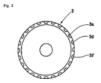
- Fig. 2 is an end view of the molded product of Figure 1(C), in the direction left to right in the drawing.
- Fig. 3 is a cross-section view of a final product formed from the molded product of Figure 1(C);
- Fig. 4(A) is a cross-section view of a raw material blank or billet;
- Fig. 4(B) is a cross-section view of an intermediate product formed from the blank of Figure 4(A);
- Fig. 4(C) is a cross-section view of a molded product formed from the intermediate product of Figure 4 (B).
- Fig. 5 is an end view of a molded product of Figure 4(C), in the direction left to right in the drawing;
- Fig. 6(A) is a process diagram of the prior art, and,
- Fig. 6(B) is a process diagram of the prior art.
-
- Referring now to Figs. 1(A) and 1(B), a malleable raw material billet or blank 1 includes a disk-shaped flange part 1a, and a tubular shaft part 1b. A radially outer part of the flange 1a has an axial thickness dimension t2, and a radially inner part has axial thickness dimension t1. The tubular shaft 1b has a radial thickness dimension t3. The thickness dimension t2 of the radially outer part of flange 1a is larger than the thickness t1 of the radially inner part. It is to be understood, that while the raw material blank 1 is the precursor to the later formed intermediate part 2 of Figure 1(B), the size, shape, and thickness of the flange part 1a and the shaft part 1b are selected to allow easy formation of the later formed intermediate product 2.
- It is to be understood that the raw material billet or blank 1 may be formed by many forming methods common in the field, but that cold forging is a commonly used and economic method since heat forging acts to abrade the forming mold and reduce precision.
- According to a first arrangement, intermediate product 2 is formed from the raw material billet or blank by drawing flange part 1a. The intermediate product 2 also includes a
tubular shaft part 2c and a flange. The flange includes a radially outer tubular part 2a and a disc part 2b which extends radially between theshaft 2c and tubular part 2a. During forming of the blank 1, the radially outer part of the flange 1a is molded thicker than the radially inner part. The raw material billet or blank 1 is designed so that, in addition to having a thinner disc part 2b, the material of the intermediate product 2 flows easily, and with lower die loads, that is to say, the flange 1a is readily deformed to form the disc 2b and tubular part 2a of the intermediate product. The formation of the raw material billet or blank 1, with the specified and shaped flange part 1a, enables the desired thickness of the tubular part 2a to be readily obtained with lower processing loads. - It is to be understood, that the thickness t1 of the radially inner part and thickness t2 of the radially outer part are determined according to the desired shape, configuration and/or other properties of the final product, the loads acting upon the forming die, considerations for additional material to form intermediate products with differing outer dimensions, or other factors. Since thickness t1, t2, and t3 are selectable, according to intermediate and final product requirements, a wide variety of final products may be manufactured using this method.
- Referring additionally to Figures 1(C), 2, and 3, the intermediate product 2 is molded in a desired manner to form a molded
product 3. The moldedproduct 3 includes an axial shaft part 3c extending from a radial flange which includes adisc part 3b and a tubular part 3a.Teeth 3d, formed from part of the material of tubular part 2a, are molded along the outer portion of the tubular part 3a anddisc part 3b. Theteeth 3d are moulded in a shape, pitch, and frequency according to specific manufacturer or customer requirements. - An
extrusion remnant 3f is formed by extrusion of the intermediate product in the region between thedisc 3b and tubular part 3a. The remnant improves the rigidity and strength of theteeth 3d by increasing the stiffness of the molded product in the region of theteeth 3d. A spline 3e is formed on the radially outer shaft 3a, during molding ofshaft part 2c for use in later assembly. - After molding, the molded
product 3 of Figure 1 (C) may be further processed by cutting, punching a hole for lubrication oil, or other manufacturing steps, to form a final component such as that shown in Figure 3. Thefinal component 4 of Figure 3 is assembled withbushings 6, and/or with other application specific items (not shown) so that the moldedproduct 3 constitutes part of an assembledproduct 4 with teeth parts 5. - Referring additionally now to Figs. 4(A), 4(B), 4(C), and 5, a second arrangement is shown for a molding process to form a toothed part with a shaft. A raw material billet or blank 11 is constructed from a disk-shaped
flange part 11a and atubular shaft part 11b extending fromflange part 11a. Theflange part 11a includes a radially outer part, having a thickness dimension in the axial direction of the disc t12 and a radially inner part having a thickness dimension in the axial direction t11. Thickness t11 is less than thickness t12. Theshaft part 11b has a thickness dimension t13 in the radial direction of the shaft. - An intermediate product 12 (Figure 4B) is formed by drawing
flange part 11a of the billet or blank 11. Theintermediate product 12 is includes a radially innertubular shaft part 12c extending from a flange part 12b. Theflange 11a of theraw material billet 11 forms a radially outer tubular part 12a parallel toshaft part 12c, and a disk part 12b, generally perpendicular toshaft part 12a and 12c. - As described above, the radially outer part of
flange part 11a is thicker than the radially inner part offlange part 11a. It is to be understood, that the thicknesses of the radially inner and outer parts are selected in accordance with considerations including requirements to provide athin disk part 12 of the final product, the loads acting on the forming die, requirements for additional material for subsequent machining, and other factors. The thickness of these parts is further selected to enable the material to readily flow in molding, with smaller loads, and still obtain the desired thickness of tubular part 12a. Since thickness t11, t12, and t13 are selectable, according to intermediate and final product requirements, a wide variety of final products may be manufactured using this method that is to say, the load acting on the die is smaller than in known methods and various intermediate products with differing outer diameters for the tubular part 12a can be readily obtained from the same raw material blank orbillet 11. - The molded
product 13 of Figure 4(C) is formed by forming teeth on the radially outer tubular part 12a and by forming a spline on theshaft part 12c. The moldedproduct 13 includes ashaft part 13c and a flange comprising adisk part 13b and atubular part 13a.Teeth 13d are formed in the inner perimeter part of thetubular part 13a, opposite the spline 13e on the radially outer surface of theshaft part 13c. Theteeth 13d are formed by extruding tubular part 12a. An extrusionremnant part 13f is presentnear disk part 13b oppositeshaft part 13c. The extrusionremnant part 13f improves the rigidity and strength of theteeth 13d. The molded product may be further machined through cutting or through punching holes for lubrication oil, such that the moldedproduct 13 becomes a final product or component. - In another arrangement, cold forging allows a manufacturer to form the raw material billet or blank 11 with precision. If the
raw material 11 were formed with heat forging, the forming die would abrade, precision would be limited, and die life would decrease. - It is to be understood, that according to either arrangements, a high precision toothed part such as an inner or outer gear with a shaft may be formed from a unitary body with high precision, without welding.
- It is to be understood, that according to either arrangement concerning the method of forming a toothed part with a shaft, the resulting toothed part with a shaft is an additional third and fourth arrangement with either the tubular part facing away from the shaft or forming a cylinder about the shaft.
- It is to be further understood, that by devising the thickness for the flange parts of the raw material and by forming the flange of the intermediate product by drawing, the load acting on the die is minimized.
- It is to be further understood, that since the load acting on the die is small the life span of the die is correspondingly increased.
- It is to be further understood, that using the arrangements herein described, a manufacturer may achieve improved near net shape rates, high rigidity and durability, and minimize production costs.
- It is to be further understood, that by forming teeth and a remnant part, according to the above arrangements, the strength and rigidity of the gear is improved.
- Having described preferred embodiments of the invention with reference to the accompanying drawings, it is to be understood that the invention is not limited to those precise embodiments, and that various changes and modifications may be effected therein by one skilled in the art without departing from the scope or spirit of the invention as defined in the appended claims.
Claims (16)
- A method of forming a metal component; the said method comprising the steps of:
providing a blank element (1) for a metal component (3), the said element having a shaft portion (1b) and a disc portion (1a) substantially coaxial with and perpendicular to the said shaft portion;
characterised in that: the said disc portion having an outer annular portion having a thickness in the axial direction of the said disc greater than the respective thickness of an adjacent radially inner portion of the said disc; and, in that the method further comprises the step of forming the material of the said radially outer annular portion of the said disc into a generally tubular portion (2a) substantially parallel to the said shaft portion. - A method as claimed in Claim 1 wherein the step of forming the tubular portion includes the step of drawing the material of the said thicker radially outer annular portion to form the said tubular portion.
- A method as claimed in Claim 1 or Claim 2 further comprising the step of forming teeth (3d) on a radially inner or outer surface of the said tubular portion, whereby the greater thickness of the said tubular portion permits formation of said teeth while retaining substantial strength.
- A method as claimed in Claim 3 wherein the said teeth are formed by extrusion of the tubular portion material.
- A method as claimed in Claim 3 or Claim 4 wherein the said teeth comprise gear teeth.
- A blank element (1) for a metal component (3), the said element comprising:
a shaft portion (1b) and a disc portion (1a) substantially coaxial with and perpendicular to the said shaft portion;
characterised in that: the said disc comprises an outer annular portion having a thickness in the axial direction of the said disc greater than the respective thickness of an adjacent radially inner portion of the said disc. - A gear and shaft component (3), comprising:characterised in that: a plurality of extruded gear teeth (3d) are provided on a radially inner or outer surface of the said tubular portion.a shaft portion (3c) and a disc portion (3b) substantially coaxial with and perpendicular to the said shaft portion;a generally tubular portion (3a) substantially parallel to the said shaft portion; the disc portion extending between the said shaft portion and the said tubular portion;
- A method for molding a toothed part with a shaft, comprising the steps of:forming a raw material blank (1), said blank including at least a shaft part (1b) and a flange part (1a), said flange part coaxial and perpendicular to said shaft part;drawing a tubular part (2a) on said flange part parallel to and away from said shaft;extruding a plurality of teeth portions (3d) on a surface of said tubular part; andextruding at least a first spline (3e) on said shaft part.
- A method for molding a toothed part with a shaft, according to claim 8, further comprising the steps of:forming said flange part into a large diameter part and a small diameter part, said large diameter part being a first portion and larger than and concentric to said small diameter part, and said large diameter part being thicker than said small diameter part; andforming a plurality of remnant parts (3f) by extrusion, said remnant parts interposed with said plurality of teeth and between said tubular part and said shaft part.
- A method for forming a metal part comprising:said disk having an outer annular portion that is thicker than a remainder of said disk;forming a blank (1) of metal to form a shaft portion (1b) and a flange portion (1a);said flange portion being a disk generally perpendicular to an axis of said shaft portion;drawing said outer annular portion into a tubular portion (2a) generally parallel to said shaft portion; andforming teeth (3d) on one of an inner and an outer surface of said tubular portion, whereby the greater thickness of said tubular portion permits formation of said teeth while retaining substantial strength.
- A toothed part with a shaft, comprising:a shaft part (1b) and a tubular part (2b) coaxial along a central axis;said tubular part extends in a first direction along said central axis;a bottom part perpendicular to said axis, between said shaft part and said tubular part;said tubular part has a first outer surface opposite to said central axis;said shaft part has a second outer surface opposite to said central axis;a plurality of teeth (3d) on said first outer surface;a plurality of extrusion remnants (3f) interposed between said teeth on said first outer surface; andat least a first spline (3e) on said second outer surface.
- A toothed element, according to claim 11 wherein:
said first direction is parallel to and away from said shaft part. - A toothed element, according to claim 11, wherein:
said first direction is parallel and concentric to said shaft part. - A method of molding a toothed part with a shaft, comprising the steps of:forming a flange part (1a) and a shaft part (1b) having a common center axis;drawing said flange part into a tubular part (2a) and a bottom part; andextruding said tubular part to form a plurality of teeth (3d).
- A method of molding a toothed part with a shaft, according to claim 14, wherein:said flange part includes a large diameter part and a small diameter part; andsaid large diameter part having a thickness greater than a thickness of said small diameter part.
- A method of molding a toothed part with a shaft, according to claim 15, wherein:
said forming a flange part and a shaft part is conducted by cold forging.
Applications Claiming Priority (2)
| Application Number | Priority Date | Filing Date | Title |
|---|---|---|---|
| JP2000093345A JP2001276955A (en) | 2000-03-30 | 2000-03-30 | Tooth form parts with shaft and its forming method |
| JP2000093345 | 2000-03-30 |
Publications (3)
| Publication Number | Publication Date |
|---|---|
| EP1138416A2 true EP1138416A2 (en) | 2001-10-04 |
| EP1138416A3 EP1138416A3 (en) | 2002-07-17 |
| EP1138416B1 EP1138416B1 (en) | 2005-07-06 |
Family
ID=18608541
Family Applications (1)
| Application Number | Title | Priority Date | Filing Date |
|---|---|---|---|
| EP01302888A Expired - Lifetime EP1138416B1 (en) | 2000-03-30 | 2001-03-28 | Gear and shaft and forming method thereof |
Country Status (4)
| Country | Link |
|---|---|
| US (1) | US6688153B2 (en) |
| EP (1) | EP1138416B1 (en) |
| JP (1) | JP2001276955A (en) |
| DE (1) | DE60111794T2 (en) |
Cited By (2)
| Publication number | Priority date | Publication date | Assignee | Title |
|---|---|---|---|---|
| RU2524883C1 (en) * | 2012-12-07 | 2014-08-10 | Открытое акционерное общество "Завод им. В.А. Дегтярева" | Method of making of precise formed articles |
| CN113369362A (en) * | 2021-06-07 | 2021-09-10 | 四川航天长征装备制造有限公司 | Method for forming cover for spaceflight |
Families Citing this family (8)
| Publication number | Priority date | Publication date | Assignee | Title |
|---|---|---|---|---|
| JP2003083357A (en) * | 2001-09-10 | 2003-03-19 | Aida Eng Ltd | Outer race of constant velocity joint and method of making it |
| JP3559784B2 (en) * | 2002-01-31 | 2004-09-02 | 株式会社カネミツ | Method of forming spline and keyway of sheet metal rotary member having boss portion |
| JP2005155857A (en) * | 2003-11-28 | 2005-06-16 | Nsk Warner Kk | Method of manufacturing clutch housing |
| US7677073B2 (en) * | 2004-10-15 | 2010-03-16 | Kondo Seiko Co., Ltd. | Method of manufacturing tooth profile part |
| US8261592B2 (en) * | 2007-04-19 | 2012-09-11 | Indimet Inc. | Method of providing a solenoid housing |
| WO2010066724A1 (en) * | 2008-12-10 | 2010-06-17 | Vestas Wind Systems A/S | A composite gear part for a gear arrangement and a method of forming a composite gear part |
| DE102011119514B4 (en) * | 2011-11-26 | 2020-11-12 | Gm Tec Industries Holding Gmbh | Gear with permanently connected drive shaft |
| JP6301125B2 (en) * | 2013-12-17 | 2018-03-28 | Ntn株式会社 | In-wheel motor drive device |
Citations (4)
| Publication number | Priority date | Publication date | Assignee | Title |
|---|---|---|---|---|
| US4739644A (en) * | 1986-12-30 | 1988-04-26 | Honda Giken Kogyo Kabushiki Kaisha | Process for forming internal gear profile cup-shaped member and apparatus therefor |
| JPH04258337A (en) * | 1991-02-12 | 1992-09-14 | Aida Eng Ltd | Method for plastic-working cup-shaped member |
| US5732586A (en) * | 1996-09-19 | 1998-03-31 | Ford Global Technologies, Inc. | Cold extrusion for helical gear teeth |
| DE19723073A1 (en) * | 1997-06-02 | 1998-12-03 | Fischer & Kaufmann Gmbh & Co K | Sheetmetal disc conversion for e.g. pulley service |
Family Cites Families (4)
| Publication number | Priority date | Publication date | Assignee | Title |
|---|---|---|---|---|
| JPS5584238A (en) * | 1978-12-21 | 1980-06-25 | Sanden Corp | Production of magnetic circuit part of solenoid clutch |
| JPS61279330A (en) * | 1985-06-04 | 1986-12-10 | Honda Motor Co Ltd | Forming method for inside and outside diameter groove of hollow parts |
| JP2597107B2 (en) * | 1987-10-05 | 1997-04-02 | 株式会社フジユニバンス | Spline forming method of hollow shaft end |
| JPH049243A (en) * | 1990-04-27 | 1992-01-14 | Kubota Tekkosho:Kk | Production of rotating body |
-
2000
- 2000-03-30 JP JP2000093345A patent/JP2001276955A/en active Pending
-
2001
- 2001-03-27 US US09/818,292 patent/US6688153B2/en not_active Expired - Fee Related
- 2001-03-28 EP EP01302888A patent/EP1138416B1/en not_active Expired - Lifetime
- 2001-03-28 DE DE60111794T patent/DE60111794T2/en not_active Expired - Lifetime
Patent Citations (4)
| Publication number | Priority date | Publication date | Assignee | Title |
|---|---|---|---|---|
| US4739644A (en) * | 1986-12-30 | 1988-04-26 | Honda Giken Kogyo Kabushiki Kaisha | Process for forming internal gear profile cup-shaped member and apparatus therefor |
| JPH04258337A (en) * | 1991-02-12 | 1992-09-14 | Aida Eng Ltd | Method for plastic-working cup-shaped member |
| US5732586A (en) * | 1996-09-19 | 1998-03-31 | Ford Global Technologies, Inc. | Cold extrusion for helical gear teeth |
| DE19723073A1 (en) * | 1997-06-02 | 1998-12-03 | Fischer & Kaufmann Gmbh & Co K | Sheetmetal disc conversion for e.g. pulley service |
Non-Patent Citations (1)
| Title |
|---|
| PATENT ABSTRACTS OF JAPAN vol. 017, no. 038 (M-1358), 25 January 1993 (1993-01-25) -& JP 04 258337 A (AIDA ENG LTD), 14 September 1992 (1992-09-14) * |
Cited By (2)
| Publication number | Priority date | Publication date | Assignee | Title |
|---|---|---|---|---|
| RU2524883C1 (en) * | 2012-12-07 | 2014-08-10 | Открытое акционерное общество "Завод им. В.А. Дегтярева" | Method of making of precise formed articles |
| CN113369362A (en) * | 2021-06-07 | 2021-09-10 | 四川航天长征装备制造有限公司 | Method for forming cover for spaceflight |
Also Published As
| Publication number | Publication date |
|---|---|
| DE60111794D1 (en) | 2005-08-11 |
| JP2001276955A (en) | 2001-10-09 |
| US20010025521A1 (en) | 2001-10-04 |
| EP1138416A3 (en) | 2002-07-17 |
| DE60111794T2 (en) | 2006-04-20 |
| US6688153B2 (en) | 2004-02-10 |
| EP1138416B1 (en) | 2005-07-06 |
Similar Documents
| Publication | Publication Date | Title |
|---|---|---|
| US5363714A (en) | Gear product | |
| EP1138416B1 (en) | Gear and shaft and forming method thereof | |
| KR20060116099A (en) | Universal joint for vehicle and manufacturing method thereof | |
| JP2015074029A (en) | Manufacturing method of primary metal fitting molded article for spark plug, manufacturing method of primary metal fitting for spark plug, and spark plug manufacturing method | |
| US7588834B2 (en) | Trimless forged products and method | |
| JP3787767B2 (en) | Method for manufacturing hooked connecting shaft | |
| JP2011121100A (en) | Helical gear and method of manufacturing it | |
| JP5056631B2 (en) | Manufacturing method of shaft | |
| JPH11230068A (en) | Manufacture of rotor | |
| EP0786307A1 (en) | Spool valve and process for manufacturing the same | |
| KR20030080982A (en) | Method of manufacturing a poppet valve | |
| US6675477B2 (en) | Method for manufacturing spool valve | |
| JPH0985385A (en) | Production of bevel gear and sizing die thereof | |
| JPH05337576A (en) | Forming method of tube end | |
| JP4856889B2 (en) | Cold forging method | |
| JPH0759341B2 (en) | Manufacturing method of integrated synchro clutch gear for synchro mechanism of transmission | |
| JP4234224B2 (en) | Groove machining method and manufacturing method for automobile steering main shaft | |
| JPH0755346B2 (en) | Manufacturing method of automobile components | |
| US3206840A (en) | Method of making a pinion and disc | |
| JP2001121238A (en) | Method for producing outer diameter side spherical shaped ring | |
| JP3023489B2 (en) | Manufacturing method of cylindrical ring type eye joint | |
| JP3128479B2 (en) | Multi-stage shaft manufacturing method | |
| JPH03290911A (en) | Manufacture of electromagnetic coil case | |
| JP2002192296A (en) | Cold forging method of bottomed spline hole and cold forged parts | |
| JP3731300B2 (en) | Manufacturing method of hose fitting, hose fitting and brake hose |
Legal Events
| Date | Code | Title | Description |
|---|---|---|---|
| PUAI | Public reference made under article 153(3) epc to a published international application that has entered the european phase |
Free format text: ORIGINAL CODE: 0009012 |
|
| AK | Designated contracting states |
Kind code of ref document: A2 Designated state(s): AT BE CH CY DE DK ES FI FR GB GR IE IT LI LU MC NL PT SE TR |
|
| AX | Request for extension of the european patent |
Free format text: AL;LT;LV;MK;RO;SI |
|
| PUAL | Search report despatched |
Free format text: ORIGINAL CODE: 0009013 |
|
| AK | Designated contracting states |
Kind code of ref document: A3 Designated state(s): AT BE CH CY DE DK ES FI FR GB GR IE IT LI LU MC NL PT SE TR |
|
| AX | Request for extension of the european patent |
Free format text: AL;LT;LV;MK;RO;SI |
|
| 17P | Request for examination filed |
Effective date: 20021017 |
|
| AKX | Designation fees paid |
Designated state(s): DE GB |
|
| 17Q | First examination report despatched |
Effective date: 20030916 |
|
| GRAP | Despatch of communication of intention to grant a patent |
Free format text: ORIGINAL CODE: EPIDOSNIGR1 |
|
| GRAS | Grant fee paid |
Free format text: ORIGINAL CODE: EPIDOSNIGR3 |
|
| GRAA | (expected) grant |
Free format text: ORIGINAL CODE: 0009210 |
|
| AK | Designated contracting states |
Kind code of ref document: B1 Designated state(s): DE GB |
|
| REG | Reference to a national code |
Ref country code: GB Ref legal event code: FG4D |
|
| REF | Corresponds to: |
Ref document number: 60111794 Country of ref document: DE Date of ref document: 20050811 Kind code of ref document: P |
|
| RAP2 | Party data changed (patent owner data changed or rights of a patent transferred) |
Owner name: AIDA ENGINEERING CO., LTD. |
|
| PLBE | No opposition filed within time limit |
Free format text: ORIGINAL CODE: 0009261 |
|
| STAA | Information on the status of an ep patent application or granted ep patent |
Free format text: STATUS: NO OPPOSITION FILED WITHIN TIME LIMIT |
|
| 26N | No opposition filed |
Effective date: 20060407 |
|
| PGFP | Annual fee paid to national office [announced via postgrant information from national office to epo] |
Ref country code: GB Payment date: 20160323 Year of fee payment: 16 |
|
| PGFP | Annual fee paid to national office [announced via postgrant information from national office to epo] |
Ref country code: DE Payment date: 20170321 Year of fee payment: 17 |
|
| GBPC | Gb: european patent ceased through non-payment of renewal fee |
Effective date: 20170328 |
|
| PG25 | Lapsed in a contracting state [announced via postgrant information from national office to epo] |
Ref country code: GB Free format text: LAPSE BECAUSE OF NON-PAYMENT OF DUE FEES Effective date: 20170328 |
|
| REG | Reference to a national code |
Ref country code: DE Ref legal event code: R119 Ref document number: 60111794 Country of ref document: DE |
|
| PG25 | Lapsed in a contracting state [announced via postgrant information from national office to epo] |
Ref country code: DE Free format text: LAPSE BECAUSE OF NON-PAYMENT OF DUE FEES Effective date: 20181002 |