EP1138250A2 - Video scope - Google Patents
Video scope Download PDFInfo
- Publication number
- EP1138250A2 EP1138250A2 EP01107959A EP01107959A EP1138250A2 EP 1138250 A2 EP1138250 A2 EP 1138250A2 EP 01107959 A EP01107959 A EP 01107959A EP 01107959 A EP01107959 A EP 01107959A EP 1138250 A2 EP1138250 A2 EP 1138250A2
- Authority
- EP
- European Patent Office
- Prior art keywords
- pickup
- picking
- holding portion
- picked
- video scope
- Prior art date
- Legal status (The legal status is an assumption and is not a legal conclusion. Google has not performed a legal analysis and makes no representation as to the accuracy of the status listed.)
- Granted
Links
Images


Classifications
-
- A—HUMAN NECESSITIES
- A61—MEDICAL OR VETERINARY SCIENCE; HYGIENE
- A61B—DIAGNOSIS; SURGERY; IDENTIFICATION
- A61B1/00—Instruments for performing medical examinations of the interior of cavities or tubes of the body by visual or photographical inspection, e.g. endoscopes; Illuminating arrangements therefor
- A61B1/24—Instruments for performing medical examinations of the interior of cavities or tubes of the body by visual or photographical inspection, e.g. endoscopes; Illuminating arrangements therefor for the mouth, i.e. stomatoscopes, e.g. with tongue depressors; Instruments for opening or keeping open the mouth
- A61B1/247—Instruments for performing medical examinations of the interior of cavities or tubes of the body by visual or photographical inspection, e.g. endoscopes; Illuminating arrangements therefor for the mouth, i.e. stomatoscopes, e.g. with tongue depressors; Instruments for opening or keeping open the mouth with means for viewing areas outside the direct line of sight, e.g. dentists' mirrors
-
- A—HUMAN NECESSITIES
- A61—MEDICAL OR VETERINARY SCIENCE; HYGIENE
- A61B—DIAGNOSIS; SURGERY; IDENTIFICATION
- A61B1/00—Instruments for performing medical examinations of the interior of cavities or tubes of the body by visual or photographical inspection, e.g. endoscopes; Illuminating arrangements therefor
- A61B1/00163—Optical arrangements
- A61B1/00174—Optical arrangements characterised by the viewing angles
- A61B1/00181—Optical arrangements characterised by the viewing angles for multiple fixed viewing angles
-
- A—HUMAN NECESSITIES
- A61—MEDICAL OR VETERINARY SCIENCE; HYGIENE
- A61B—DIAGNOSIS; SURGERY; IDENTIFICATION
- A61B1/00—Instruments for performing medical examinations of the interior of cavities or tubes of the body by visual or photographical inspection, e.g. endoscopes; Illuminating arrangements therefor
- A61B1/06—Instruments for performing medical examinations of the interior of cavities or tubes of the body by visual or photographical inspection, e.g. endoscopes; Illuminating arrangements therefor with illuminating arrangements
- A61B1/0661—Endoscope light sources
- A61B1/0676—Endoscope light sources at distal tip of an endoscope
-
- A—HUMAN NECESSITIES
- A61—MEDICAL OR VETERINARY SCIENCE; HYGIENE
- A61B—DIAGNOSIS; SURGERY; IDENTIFICATION
- A61B1/00—Instruments for performing medical examinations of the interior of cavities or tubes of the body by visual or photographical inspection, e.g. endoscopes; Illuminating arrangements therefor
- A61B1/06—Instruments for performing medical examinations of the interior of cavities or tubes of the body by visual or photographical inspection, e.g. endoscopes; Illuminating arrangements therefor with illuminating arrangements
- A61B1/0661—Endoscope light sources
- A61B1/0684—Endoscope light sources using light emitting diodes [LED]
-
- A—HUMAN NECESSITIES
- A61—MEDICAL OR VETERINARY SCIENCE; HYGIENE
- A61B—DIAGNOSIS; SURGERY; IDENTIFICATION
- A61B2562/00—Details of sensors; Constructional details of sensor housings or probes; Accessories for sensors
- A61B2562/02—Details of sensors specially adapted for in-vivo measurements
- A61B2562/0233—Special features of optical sensors or probes classified in A61B5/00
- A61B2562/0238—Optical sensor arrangements for performing transmission measurements on body tissue
Definitions
- the present invention relates to a video scope incorporating a solid state imaging device such as CCD, and more particularly to a video scope to be used for photographing a diseased part within an oral cavity in dental surgery, an oral cavity surgical department, or the like.
- a dental mirror with a small diameter was generally used at the time of examining a state of the interior of an oral cavity in the dental surgery, but in recent years, in the observation of the interior of an oral cavity, and informed consent in which an image on a monitor TV is shown to a patient for explanation, or the like, a video scope using a solid state imaging device such as CCD has been put to practical use.
- the present invention has been achieved in the light of such points, and is aimed, for example, to provide a simple, easy-to-use video scope capable of picking up an object to be picked up from at least two directions at the same time, picking up an image in a short time and easily pigeonholing data obtained by picking up, and further easily picking up a crack in the object to be picked up.
- the 1st invention of the present invention is a video scope, comprising:
- Avideo scope according to the present invention is capable of picking up an image for the object to be picked up from plural directions easily in a short time. Also, since images from plural directions are picked up at the same time, it is easy to specify which object to be picked up an image obtained by picking up is, and it is easy to pigeonhole data obtained by picking up.
- the 2nd invention of the present invention is the video scope according to 1st invention
- the 3rd invention of the present invention is the video scope according to 1st invention
- any solid state imaging device becomes unnecessary for wing portions within the pickup holding portion, and therefore, the wing portions within the pickup holding portion become smaller in a widthwise direction, and as a result, the pickup holding portion can be miniaturized.
- the 4th invention of the present invention is the video scope according to 1st invention, wherein said pickup holding portion is substantially quasi-horse-shaped having a central portion and two wing portions, which are located at both ends of said central portion so as to oppose to each other, wherein the picking up means of picking up an object to be picked up has a first pickup system provided within said central portion of said pickup holding portion, including at least an objective lens and a solid state imaging device, a light source provided within one of said wing portions, and a second pickup system provided within the other of said wing portions, including at least an objective lens and a solid state imaging device.
- the central portion of the substantially quasi-horse-shaped pickup holding portion is caused to abut upon the portion to be picked up for picking up, whereby the distance between the object to be picked up and the pickup system is fixed, and image shakes due to hand shakes are eliminated, and therefore, it is not necessary to achieve focus, resulting in excellent operability.
- transmitted light from a light source provided in one of the wing portions within the pickup holding portion is picked up, whereby it is possible to easily observe a crack in the object to be picked up.
- the 5th invention of the present invention is the video scope according to any one of 2nd to 4th inventions, further comprising an incident window for pickup light in an inner wall of said central portion of said pickup holding portion and in inner walls of said two wing portions respectively.
- the pickup holding portion can be made into an airtight or watertight structure, and therefore, it is possible to prevent any foreign matter from entering the interior of the pickup holding portion to affect the pickup system and to easily wash it.
- the 6th invention of the present invention is the video scope according to any one of 1st to 5th inventions, wherein the tip end of said entering portion is bent, and said pickup holding portion is pivotally provided at the tip end of said entering portion.
- An object and an object to be picked up which are used in the present invention are both not particularly limited, but if the object is the interior of an oral cavity and the object to be picked up is a tooth, especially high effect will be obtained.
- Any solid state imaging device may be used as long as it can be installed within the pickup holding portion and can pick up an object to be picked up, and for example, a CCD imaging device, a MOS type imaging device or the like can be named.
- the reflector is not particularly limited, but for example, a prism mirror, a mirror or the like can be used.
- Any light source may be used as long as it can be installed within the pickup holding portion and has sufficient illuminance for picking up the object to be picked up, and for example, a lamp, a LED or the like can be named.
- a white LED has lower power consumption than lamps, and has a long life, and therefore it is maintenance-free, and is preferable.
- Any incident window may be used as long as it is made of material capable of guiding image pickup light, and for example, glass, transparent resin or the like can be named.
- the shape may be the substantially quasi-horse-shaped, and windows divided in three surfaces of the pickup holding portion respectively may be used.
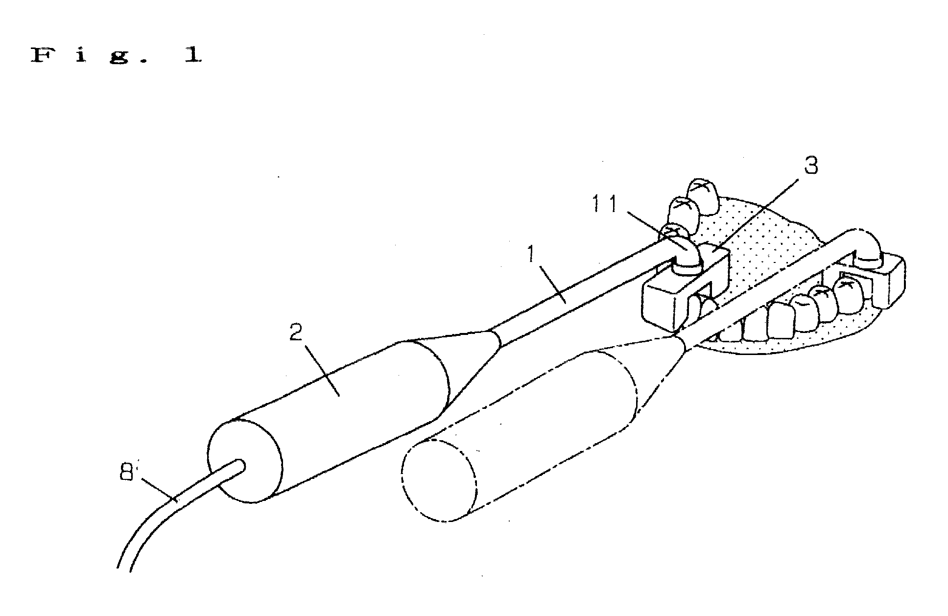
- FIG. 1 is an external view showing a video scope
- FIG. 2 is a partially enlarged sectional view for the video scope
- FIGS. 3A to 3C are actual views showing an image for the interior of the oral cavity obtained by picking up with the same video scope.
- reference numeral 1 denotes an entering portion for entering the interior of the oral cavity, which is the object; and 2, a grip portion which an operator holds in one hand.
- the entering portion 1 has, at its tip end portion, a bent entering portion 11 which is bent.
- a substantially quasi-horse-shaped pickup holding portion 3 is mounted air-tightly or water-tightly and pivotally with an opening side of a substantially quasi-horse-shaped directed downward. It is made into the air-tight or water-tight structure in order to prevent saliva or the like from entering.
- an angle of rotation is preferably about 180°.
- an incident window 4 made of glass capable of guiding image pickup light respectively.
- a pickup system provided with a CCD unit 6, which is a solid state imaging device, and an objective lens 5, and a white LED 7 as a light source for throwing light are incorporated respectively, and illumination light is thrown through the incident window 4.
- the objective lens 5 is provided with an iris diaphragm, but it is omitted in this figure.
- a camera circuit for operating the CCD unit 6 and the white LED 7 is incorporated, and power supply for driving the camera circuit and the white LED7 is mounted.
- power supply low voltage power supply such as, for example, an alkaline battery, a lithium battery and a charging type battery can be used, and a combination of a detachable battery pack and a charger may be used.
- the camera circuit and power supply are omitted in this figure.
- a video output cable 8 connected to a display such as a monitor TV is drawn out.
- This video output cable 8 is water-tightly configured over the rear from within the grip portion 2.
- these camera circuit and power supply may not be incorporated in the grip portion 2, but be configured separately.
- a range of about one tooth can be observed for a molar, and a range of about three teeth can be observed for a small tooth such as a fore-tooth and a dogtooth.
- a video scope according to the present embodiment is capable of observing a clenched teeth surface (FIG. 3B) of teeth, the back side of a tooth, which is the inner part of the oral cavity, and its gum portion (FIG. 3A), and the surface side of a tooth, which is the lip side, and its gum portion (FIG. 3C) at the same time as shown in FIG. 3 through the use of three pickup systems by inserting the entering portion 1 into the oral cavity holding the grip portion 2 to cause the pickup holding portion 3 to abut upon a tooth 14 in such a manner as to cover the tooth 14, which is the object to be picked up, with the substantially quasi-horse-shaped.
- the lip is kept out of the way of the entering portion 1 by rotating the pickup holding portion 3 as shown in a chain line in FIG. 1, and therefore it is easy to use.
- the pickup holding portion 3 is caused to be in contact with the tooth 14, the distance between the tooth 14 and the pickup system is fixed, no image shakes due to hand shakes are caused, there is no need for focusing, and the pickup holding portion 3 can be caused to slide along the tooth 14 while being in contact therewith. Therefore, it has excellent operability.
- the system has image storing means of storing an image, the image data will be able to be simply pigeonholed.
- FIG. 4 is a partially enlarged sectional view for a video scope, and in FIG. 4, on the inner surface of a substantially quasi-horse-shaped pickup holding portion 3, an incident window 4 made of glass capable of guiding light is hermetically fixed.
- Reference numeral 7 denotes a white LED for throwing light, and the light is thrown through the incident window 4.
- a mirror 9 is incorporated as a reflector for side viewing.
- a pickup system provided with an objective lens 5 and a CCD unit 6, and on both sides thereof, pickup systems, each provided with an objective lens 5 for focusing an input image from a mirror 9 and a CCD unit 6 are fixed in parallel on a substrate 10 and are incorporated.
- the objective lens 5 is provided with an iris diaphragm, but it is omitted in this drawing.
- the configuration of portions other than the pickup holding portion 3 is the same as in the first embodiment, and as shown in FIG. 1, the pickup holding portion 3 is pivotally mounted'onto a bent entering portion 11 at the tip end of the entering portion 1.
- a video scope according to the present embodiment is capable of picking up images for a tooth 14, which is a object to be picked up, at the same time from three directions through the use of the pickup systems and two mirrors 9, and the configuration of portions other than the pickup holding portion 3 is the same as in the first embodiment. Therefore, the same effects as in the first embodiment can be obtained.
- the configuration in which three CCD units 6 are fixed to the substrate 10 has been used, but in place thereof, there may be used a configuration, in which one CCD unit is fixed onto the substrate 10, and at the central portion of the CCD unit, an image for the object to be picked up which has passed through the objective lens 5 without passing through the mirror 9 is directly inputted, and at end portions of the CCD unit, an image for the object to be picked up which has passed through the objective lens 5 through the mirror 9 is inputted.
- the mirror 9 is set to an appropriate angle depending upon a size of the CCD unit, positions of the objective lenses or the like.
- FIG. 5 is a partially enlarged sectional view for the video scope; and FIG. 6 is an actual view partially showing an image for the interior of the oral cavity obtained by picking up with the same video scope.
- an incident window 4 made of glass capable of guiding light is hermetically fixed.
- a-first pickup system provided with an objective lens 5 and a CCD unit 6 is incorporated in the central portion 12
- a white LED 7 as a light source is provided facing the opposite side in one of the wing portions 13
- a second pickup system provided with an objective lens 5 and a CCD unit 6 is incorporated in the other wing portion 13.
- the objective lens 5 is provided with an iris diaphragm, but it is omitted in this figure.
- the configuration of portions other than the pickup holding portion 3 is the same as in the first embodiment, and as shown in FIG. 1, the pickup holding portion 3 is pivotally mounted onto a bent entering portion 11 at the tip end of the entering portion 1.
- a video scope according to the present embodiment is capable of observing a clenched surface of teeth, the back side of a tooth, which is the inner part of the oral cavity, and its gum portion, or the surface side of a tooth, which is the lip side, and its gum portion at the same time through the use of the first and second pickup systems by inserting the entering portion 1 into the oral cavity, which is an object, holding the grip portion 2 to cause the pickup holding portion 3 to abut upon a tooth 14 in such a manner as to cover the tooth 14, which is the object to be picked up, with the substantially quasi-horse-shaped.
- the lip is kept out of the way of the entering portion 1 even when a back tooth such as a molar is observed and therefore it is easy to use.
- the pickup holding portion 3 is caused to be in contact with the tooth 14 in the same way as the first embodiment, the distance between the tooth 14 and the pickup system is fixed, and no image shakes due to hand shakes are caused, there is no need for focusing, and the pickup holding portion 3 can be caused to slide along the tooth 14 while being in contact therewith. Therefore, it has excellent operability.
- the system has image storing means of storing an image, the image data will be able to be simply pigeonholed.
- a white LED provided within one of the wing portions of the pickup holding portion is switched off, and through the use of the CCD unit provided there, transmitted light, which permeated the tooth, from the white LED provided within the other wing portion is picked up, whereby a crack in the tooth can be easily observed in the same way as the video scope according to the third embodiment.
- a video scope according to the present invention is capable of picking up an object to be picked up from at least two directions at the same time, simply and easily picking up in a short time, and easily pigeonholing data obtained by picking up.
Abstract
Description
- The present invention relates to a video scope incorporating a solid state imaging device such as CCD, and more particularly to a video scope to be used for photographing a diseased part within an oral cavity in dental surgery, an oral cavity surgical department, or the like.
- In recent years , in dental surgery, an oral cavity surgical department or the like, our way of thinking has advanced from medical treatment to prevention. This preventive medical examination starts with grasping the state of the interior of a patient's oral cavity, and as its method, a photograph for the interior of oral cavity has been taken through the use of a video scope using a solid state imaging device such as CCD, and has been preserved as a record.
- Also, conventionally, a dental mirror with a small diameter was generally used at the time of examining a state of the interior of an oral cavity in the dental surgery, but in recent years, in the observation of the interior of an oral cavity, and informed consent in which an image on a monitor TV is shown to a patient for explanation, or the like, a video scope using a solid state imaging device such as CCD has been put to practical use.
- As such a conventional video scope, there is a video scope for holding it in one hand to pick up a tooth from the oral cavity or by inserting the tip end portion into the oral cavity as disclosed in Japanese Patent Laid-Open No. 8-332170 (USP5,745,165).
- However, since such a conventional video scope photographs teeth in units of one tooth or a plurality of teeth through a pickup incident window provided at a place on the side, the inclined plane of the tip end or the end surface thereof only from one direction, there is a problem that in order to pick up the inner part (the back side) of the oral cavity, the lip side (the surface side) and the clenched teeth surface side for all teeth, there are a great number of times of movement and image pickup and it takes a lot of time.
- Also, since the back side, the surface side and the clenched teeth surface side of all the teeth are separately picked up, it is difficult to specify which tooth an image obtained by picking up indicates, when an image is picked up by holding a video scope from the same direction, it is difficult to pigeonhole the pickup data because the image is turned upside down between the back side and the surface side of the tooth, or between an upper chin tooth and a lower chin tooth.
- Also, since a distance between a tooth, which is an object to be picked up, and the video scope is prone to fluctuate, it is necessary to correct image shakes due to hand shakes, thus necessitating a complicated operation.
- Also, in the case of a disease in which a teeth is cracked, it is difficult to find out the position of the crack in pickup from one direction, and to observe it.
- The present invention has been achieved in the light of such points, and is aimed, for example, to provide a simple, easy-to-use video scope capable of picking up an object to be picked up from at least two directions at the same time, picking up an image in a short time and easily pigeonholing data obtained by picking up, and further easily picking up a crack in the object to be picked up.
- The 1st invention of the present invention is a video scope, comprising:
- a grip portion to be held by an operator;
- an entering portion for entering an object; and
- a pickup holding portion provided at a tip end of said entering portion, wherein said pickup holding portion is provided with picking up means of picking up an object to be picked up from at least two directions.
-
- Avideo scope according to the present invention is capable of picking up an image for the object to be picked up from plural directions easily in a short time. Also, since images from plural directions are picked up at the same time, it is easy to specify which object to be picked up an image obtained by picking up is, and it is easy to pigeonhole data obtained by picking up.
- The 2nd invention of the present invention is the video scope according to 1st invention,
- wherein said pickup holding portion is substantially quasi-horse-shaped having a central portion and two wing portions , which are located at both ends of said central portion so as to oppose to each other, and
- the picking up means of picking up an object to be picked up has a pickup system including at least an objective lens and a solid state imaging device, and
- said picking up means is provided within said central portion of said pickup holding portion and within said two wing portions respectively.
-
- By doing in this way, it is possible to easily pick up images for the object to be picked up from three directions through the use of three pickup systems in a short time. Also, a central portion of a substantially quasi-horse-shaped pickup holding portion is caused to abut upon a portion to be picked up for picking up, whereby the distance between the object to be picked up and the pickup system is fixed, and image shakes due to hand shakes are eliminated, and therefore, it is not necessary to achieve focus, resulting in excellent operability.
- The 3rd invention of the present invention is the video scope according to 1st invention,
- wherein said pickup holding portion is substantially quasi-horse-shaped having a central portion and two wing portions , which are located at both ends of said central portion so as to oppose to each other, and
- the picking up means of picking up an object to be picked up has a pickup system provided within said central portion of said pickup holding portion, including at least an objective lens and a solid state imaging device, and reflectors provided within said two wing portions respectively.
-
- Then, in addition to the above described effects, any solid state imaging device becomes unnecessary for wing portions within the pickup holding portion, and therefore, the wing portions within the pickup holding portion become smaller in a widthwise direction, and as a result, the pickup holding portion can be miniaturized.
- The 4th invention of the present invention is the video scope according to 1st invention, wherein said pickup holding portion is substantially quasi-horse-shaped having a central portion and two wing portions, which are located at both ends of said central portion so as to oppose to each other, wherein the picking up means of picking up an object to be picked up has a first pickup system provided within said central portion of said pickup holding portion, including at least an objective lens and a solid state imaging device, a light source provided within one of said wing portions, and a second pickup system provided within the other of said wing portions, including at least an objective lens and a solid state imaging device.
- Also, by dosing so, it is possible to pick up images for the object to be picked up from two directions easily in a short time through the use of first and second pickup systems .
- Also, the central portion of the substantially quasi-horse-shaped pickup holding portion is caused to abut upon the portion to be picked up for picking up, whereby the distance between the object to be picked up and the pickup system is fixed, and image shakes due to hand shakes are eliminated, and therefore, it is not necessary to achieve focus, resulting in excellent operability.
- Further, through the use of the second pickup system, transmitted light from a light source provided in one of the wing portions within the pickup holding portion is picked up, whereby it is possible to easily observe a crack in the object to be picked up.
- The 5th invention of the present invention is the video scope according to any one of 2nd to 4th inventions, further comprising an incident window for pickup light in an inner wall of said central portion of said pickup holding portion and in inner walls of said two wing portions respectively.
- In the foregoing, with the provision of an incident window, the pickup holding portion can be made into an airtight or watertight structure, and therefore, it is possible to prevent any foreign matter from entering the interior of the pickup holding portion to affect the pickup system and to easily wash it.
- Then, it is possible to change angles between a grip portion, an entering portion and the pickup holding portion in accordance with a shape of the portion to be picked up, resulting in excellent operability.
- The 6th invention of the present invention is the video scope according to any one of 1st to 5th inventions, wherein the tip end of said entering portion is bent, and said pickup holding portion is pivotally provided at the tip end of said entering portion.
- An object and an object to be picked up which are used in the present invention are both not particularly limited, but if the object is the interior of an oral cavity and the object to be picked up is a tooth, especially high effect will be obtained.
- Any solid state imaging device may be used as long as it can be installed within the pickup holding portion and can pick up an object to be picked up, and for example, a CCD imaging device, a MOS type imaging device or the like can be named.
- The reflector is not particularly limited, but for example, a prism mirror, a mirror or the like can be used.
- Any light source may be used as long as it can be installed within the pickup holding portion and has sufficient illuminance for picking up the object to be picked up, and for example, a lamp, a LED or the like can be named. Of these, a white LED has lower power consumption than lamps, and has a long life, and therefore it is maintenance-free, and is preferable.
- Any incident window may be used as long as it is made of material capable of guiding image pickup light, and for example, glass, transparent resin or the like can be named. The shape may be the substantially quasi-horse-shaped, and windows divided in three surfaces of the pickup holding portion respectively may be used.
-
- FIG. 1 is an external view showing a video scope according to an embodiment of the present invention;
- FIG. 2 is a partially enlarged sectional view for the video scope according to an embodiment of the present invention;
- FIGS. 3A to 3C are actual views showing an image obtained by picking up with the video scope according to an embodiment of the present invention;
- FIG. 4 is a partially enlarged sectional view for a video scope according to another embodiment of the present invention;
- FIG. 5 is a partially enlarged sectional view for a video scope according to another embodiment of the present invention; and
- FIG. 6 is an actual view showing an image obtained by picking up with a video scope according to another embodiment of the present invention.
-
-
- 1
- Entering Portion
- 2
- Grip Portion
- 3
- Pickup Holding Portion
- 4
- Incident Window
- 5
- Objective Lens
- 6
- CCD Unit
- 7
- White LED
- 8
- Video Output Cable
- 9
- Mirror
- 10
- Substrate
- 11
- Bent Entering Portion
- 12
- Central Portion
- 13
- Wing Portion
- 14
- Tooth
- Next, with reference to FIGS. 1 to 3, the description will be made of a first embodiment of the present invention.
- FIG. 1 is an external view showing a video scope; FIG. 2 is a partially enlarged sectional view for the video scope; and FIGS. 3A to 3C are actual views showing an image for the interior of the oral cavity obtained by picking up with the same video scope.
- In FIGS. 1 and 2,
reference numeral 1 denotes an entering portion for entering the interior of the oral cavity, which is the object; and 2, a grip portion which an operator holds in one hand. The enteringportion 1 has, at its tip end portion, a bent enteringportion 11 which is bent. At the tip end of the bent enteringportion 11, a substantially quasi-horse-shapedpickup holding portion 3 is mounted air-tightly or water-tightly and pivotally with an opening side of a substantially quasi-horse-shaped directed downward. It is made into the air-tight or water-tight structure in order to prevent saliva or the like from entering. In order to enable thepickup holding portion 3 to rotate up to a position parallel with or to orthogonally intersect the enteringportion 1, an angle of rotation is preferably about 180°. - On an inner wall in the
central portion 12 and inner walls of twowing portions 13 in the substantially quasi-horse-shaped portion of thepickup holding portion 3, there is hermetically formed anincident window 4 made of glass capable of guiding image pickup light respectively. - Further, inside the
central portion 12 of thepickup holding portion 3, and inside twowing portions 13 located to oppose to each other at both ends of thecentral portion 12, a pickup system provided with aCCD unit 6, which is a solid state imaging device, and anobjective lens 5, and awhite LED 7 as a light source for throwing light are incorporated respectively, and illumination light is thrown through theincident window 4. - The
objective lens 5 is provided with an iris diaphragm, but it is omitted in this figure. - In the
grip portion 2, a camera circuit for operating theCCD unit 6 and thewhite LED 7 is incorporated, and power supply for driving the camera circuit and the white LED7 is mounted. For this power supply, low voltage power supply such as, for example, an alkaline battery, a lithium battery and a charging type battery can be used, and a combination of a detachable battery pack and a charger may be used. The camera circuit and power supply are omitted in this figure. - From the rear of the
grip portion 2, avideo output cable 8 connected to a display such as a monitor TV is drawn out. Thisvideo output cable 8 is water-tightly configured over the rear from within thegrip portion 2. - Also, these camera circuit and power supply may not be incorporated in the
grip portion 2, but be configured separately. - Also, as regards the angle of view, a range of about one tooth can be observed for a molar, and a range of about three teeth can be observed for a small tooth such as a fore-tooth and a dogtooth.
- A video scope according to the present embodiment is capable of observing a clenched teeth surface (FIG. 3B) of teeth, the back side of a tooth, which is the inner part of the oral cavity, and its gum portion (FIG. 3A), and the surface side of a tooth, which is the lip side, and its gum portion (FIG. 3C) at the same time as shown in FIG. 3 through the use of three pickup systems by inserting the entering
portion 1 into the oral cavity holding thegrip portion 2 to cause thepickup holding portion 3 to abut upon atooth 14 in such a manner as to cover thetooth 14, which is the object to be picked up, with the substantially quasi-horse-shaped. - Also, since images from three directions can be picked up at the same time, time required for picking up canbe shortened, the consultation time can be shortened, and it is easy to specify which object to be picked up an image obtained by picking up is, and it is easy to pigeonhole the data obtained by picking up.
- At the time of observing a back tooth such as a molar, the lip is kept out of the way of the entering
portion 1 by rotating thepickup holding portion 3 as shown in a chain line in FIG. 1, and therefore it is easy to use. - Also, since the
pickup holding portion 3 is caused to be in contact with thetooth 14, the distance between thetooth 14 and the pickup system is fixed, no image shakes due to hand shakes are caused, there is no need for focusing, and thepickup holding portion 3 can be caused to slide along thetooth 14 while being in contact therewith. Therefore, it has excellent operability. - Also, if the system has image storing means of storing an image, the image data will be able to be simply pigeonholed.
- Next, with reference to FIG. 4, the description will be made of a second embodiment of the present invention.
- FIG. 4 is a partially enlarged sectional view for a video scope, and in FIG. 4, on the inner surface of a substantially quasi-horse-shaped
pickup holding portion 3, anincident window 4 made of glass capable of guiding light is hermetically fixed.Reference numeral 7 denotes a white LED for throwing light, and the light is thrown through theincident window 4. - Within two
wing portions 13 of thepickup holding portion 3, amirror 9 is incorporated as a reflector for side viewing. - Also, inside the
central portion 12 of thepickup holding portion 3, a pickup system provided with anobjective lens 5 and aCCD unit 6, and on both sides thereof, pickup systems, each provided with anobjective lens 5 for focusing an input image from amirror 9 and aCCD unit 6 are fixed in parallel on asubstrate 10 and are incorporated. - The
objective lens 5 is provided with an iris diaphragm, but it is omitted in this drawing. - The configuration of portions other than the
pickup holding portion 3 is the same as in the first embodiment, and as shown in FIG. 1, thepickup holding portion 3 is pivotally mounted'onto a bent enteringportion 11 at the tip end of the enteringportion 1. - A video scope according to the present embodiment is capable of picking up images for a
tooth 14, which is a object to be picked up, at the same time from three directions through the use of the pickup systems and twomirrors 9, and the configuration of portions other than thepickup holding portion 3 is the same as in the first embodiment. Therefore, the same effects as in the first embodiment can be obtained. - In addition, three
CCD units 6 are fixed onto one sheet ofsubstrate 10, whereby the configuration of the interior of thepickup holding portion 3 and wiring are simplified, and there are no CCD units within thewing portions 13 of thepickup holding portion 3. Therefore, thewing portions 13 of thepickup holding portion 3 become smaller in a widthwise direction, and as a result, the pickup holding portion can be miniaturized. - In the present embodiment, the configuration in which three
CCD units 6 are fixed to thesubstrate 10 has been used, but in place thereof, there may be used a configuration, in which one CCD unit is fixed onto thesubstrate 10, and at the central portion of the CCD unit, an image for the object to be picked up which has passed through theobjective lens 5 without passing through themirror 9 is directly inputted, and at end portions of the CCD unit, an image for the object to be picked up which has passed through theobjective lens 5 through themirror 9 is inputted. At this time, themirror 9 is set to an appropriate angle depending upon a size of the CCD unit, positions of the objective lenses or the like. - Next, with reference to FIGS. 5 and 6, the description will be made of a third embodiment of the present invention.
- FIG. 5 is a partially enlarged sectional view for the video scope; and FIG. 6 is an actual view partially showing an image for the interior of the oral cavity obtained by picking up with the same video scope.
- In FIG. 5, on the inner surface of the substantially quasi-horse-shaped
pickup holding portion 3, anincident window 4 made of glass capable of guiding light is hermetically fixed. - Within the
pickup holding portion 3, a-first pickup system provided with anobjective lens 5 and aCCD unit 6 is incorporated in thecentral portion 12, awhite LED 7 as a light source is provided facing the opposite side in one of thewing portions 13, and a second pickup system provided with anobjective lens 5 and aCCD unit 6 is incorporated in theother wing portion 13. - The
objective lens 5 is provided with an iris diaphragm, but it is omitted in this figure. - The configuration of portions other than the
pickup holding portion 3 is the same as in the first embodiment, and as shown in FIG. 1, thepickup holding portion 3 is pivotally mounted onto a bent enteringportion 11 at the tip end of the enteringportion 1. - A video scope according to the present embodiment is capable of observing a clenched surface of teeth, the back side of a tooth, which is the inner part of the oral cavity, and its gum portion, or the surface side of a tooth, which is the lip side, and its gum portion at the same time through the use of the first and second pickup systems by inserting the entering
portion 1 into the oral cavity, which is an object, holding thegrip portion 2 to cause thepickup holding portion 3 to abut upon atooth 14 in such a manner as to cover thetooth 14, which is the object to be picked up, with the substantially quasi-horse-shaped. - Also, since images from two directions can be picked up at the same time, time required for picking up can be shortened, the consultation time can be shortened, it is easy to specify which object to be picked up an image obtained by picking up is, and it is easy to pigeonhole the data obtained by picking up.
- Since the
pickup holding portion 3 is pivotally mounted at the tip end of the enteringportion 1 in the same way as the first embodiment, the lip is kept out of the way of the enteringportion 1 even when a back tooth such as a molar is observed and therefore it is easy to use. - Also, since the
pickup holding portion 3 is caused to be in contact with thetooth 14 in the same way as the first embodiment, the distance between thetooth 14 and the pickup system is fixed, and no image shakes due to hand shakes are caused, there is no need for focusing, and thepickup holding portion 3 can be caused to slide along thetooth 14 while being in contact therewith. Therefore, it has excellent operability. - Also, if the system has image storing means of storing an image, the image data will be able to be simply pigeonholed.
- Further, through the use of the second pickup system, transmitted light from the white LED7 which has permeated the
tooth 14 is picked up, whereby if thetooth 14 is cracked, its portion appears on the screen as shown in FIG. 6, and can be easily observed. - In this respect, through the use of a video scope according to the first embodiment, a white LED provided within one of the wing portions of the pickup holding portion is switched off, and through the use of the CCD unit provided there, transmitted light, which permeated the tooth, from the white LED provided within the other wing portion is picked up, whereby a crack in the tooth can be easily observed in the same way as the video scope according to the third embodiment.
- As described above, a video scope according to the present invention, for example, is capable of picking up an object to be picked up from at least two directions at the same time, simply and easily picking up in a short time, and easily pigeonholing data obtained by picking up.
- Also, a crack on the object to be picked up can be easily picked up.
Claims (6)
- A video scope, comprising:a grip portion to be held by an operator;an entering portion for entering an object; anda pickup holding portion provided at a tip end of said entering portion, wherein said pickup holding portion is provided with picking up means of picking up an object to be picked up from at least two directions.
- The video scope according to claim 1,wherein said pickup holding portion is substantially quasi-horse-shaped having a central portion and two wing portions , which are located at both ends of said central portion so as to oppose to each other, andthe picking up means of picking up an object to be picked up has a pickup system including at least an objective lens and a solid state imaging device, andsaid picking up means is provided within said central portion of said pickup holding portion and within said two wing portions respectively.
- The video scope according to claim 1,wherein said pickup holding portion is substantially quasi-horse-shaped having a central portion and two wing portions , which are located at both ends of said central portion so as to oppose to each other, andthe picking up means of picking up an object to be picked up has a pickup system provided within said central portion of said pickup holding portion, including at least an objective lens and a solid state imaging device, and reflectors provided within said two wing portions respectively.
- The video scope according to claim 1, wherein said pickup holding portion is substantially quasi-horse-shaped having a central portion and two wing portions, which are located at both ends of said central portion so as to oppose to each other, wherein the picking up means of picking up an object to be picked up has a first pickup system provided within said central portion of said pickup holding portion, including at least an objective lens and a solid state imaging device, a light source provided within one of said wing portions, and a second pickup system provided within the other of said wing portions, including at least an objective lens and a solid state imaging device.
- The video scope according to any one of claims 2 to 4, further comprising an incident window for pickup light in an inner wall of said central portion of said pickup holding portion and in inner walls of said two wing portions respectively.
- The video scope according to any one of claims 1 to 5, wherein the tip end of said entering portion is bent, and said pickup holding portion is pivotally provided at the tip end of said entering portion.
Applications Claiming Priority (2)
| Application Number | Priority Date | Filing Date | Title |
|---|---|---|---|
| JP2000090340 | 2000-03-29 | ||
| JP2000090340A JP2001275964A (en) | 2000-03-29 | 2000-03-29 | Video scope |
Publications (3)
| Publication Number | Publication Date |
|---|---|
| EP1138250A2 true EP1138250A2 (en) | 2001-10-04 |
| EP1138250A3 EP1138250A3 (en) | 2002-08-21 |
| EP1138250B1 EP1138250B1 (en) | 2004-09-15 |
Family
ID=18605957
Family Applications (1)
| Application Number | Title | Priority Date | Filing Date |
|---|---|---|---|
| EP01107959A Expired - Lifetime EP1138250B1 (en) | 2000-03-29 | 2001-03-28 | Video scope |
Country Status (4)
| Country | Link |
|---|---|
| US (1) | US6561972B2 (en) |
| EP (1) | EP1138250B1 (en) |
| JP (1) | JP2001275964A (en) |
| DE (1) | DE60105471T2 (en) |
Cited By (2)
| Publication number | Priority date | Publication date | Assignee | Title |
|---|---|---|---|---|
| WO2007018429A1 (en) * | 2005-08-10 | 2007-02-15 | Vetjens Marinus Johannes Petru | Oral measuring system |
| WO2022043911A1 (en) * | 2020-08-28 | 2022-03-03 | Dental Scanner Solutions Kft. | Dental scanner apparatus |
Families Citing this family (36)
| Publication number | Priority date | Publication date | Assignee | Title |
|---|---|---|---|---|
| US6767321B2 (en) * | 1999-10-04 | 2004-07-27 | Robert Czarnek | Stereo laparoscope with discrete working distance |
| US7787939B2 (en) | 2002-03-18 | 2010-08-31 | Sterling Lc | Miniaturized imaging device including utility aperture and SSID |
| US20060146172A1 (en) * | 2002-03-18 | 2006-07-06 | Jacobsen Stephen C | Miniaturized utility device having integrated optical capabilities |
| US8614768B2 (en) | 2002-03-18 | 2013-12-24 | Raytheon Company | Miniaturized imaging device including GRIN lens optically coupled to SSID |
| US6781761B2 (en) * | 2002-08-29 | 2004-08-24 | Mark A. Raymond | Lenticular lens system and method for use in producing images with clear-walled containers |
| US6908307B2 (en) * | 2003-02-03 | 2005-06-21 | Schick Technologies | Dental camera utilizing multiple lenses |
| US7657125B2 (en) * | 2004-08-02 | 2010-02-02 | Searete Llc | Time-lapsing data methods and systems |
| US9155373B2 (en) | 2004-08-02 | 2015-10-13 | Invention Science Fund I, Llc | Medical overlay mirror |
| US7584534B2 (en) * | 2005-01-10 | 2009-09-08 | Perceptron, Inc. | Remote inspection device |
| WO2006086106A2 (en) * | 2005-01-10 | 2006-08-17 | Perceptron, Inc. | Optical snake |
| IL166595A0 (en) * | 2005-01-31 | 2006-01-15 | Uri Neta | Image acquisition system |
| RU2433802C2 (en) * | 2005-11-04 | 2011-11-20 | Дзе Проктер Энд Гэмбл Компани | Electric device for oral cavity care |
| US20070225556A1 (en) * | 2006-03-23 | 2007-09-27 | Ethicon Endo-Surgery, Inc. | Disposable endoscope devices |
| EP1932489B1 (en) * | 2006-11-30 | 2019-07-03 | W & H Dentalwerk Bürmoos GmbH | Medical handpiece with a lighting device |
| US7835074B2 (en) * | 2007-06-05 | 2010-11-16 | Sterling Lc | Mini-scope for multi-directional imaging |
| US7969659B2 (en) * | 2008-01-11 | 2011-06-28 | Sterling Lc | Grin lens microscope system |
| US20090227875A1 (en) * | 2008-03-04 | 2009-09-10 | Cao Group, Inc. | Three-dimensional Imaging System |
| US20090326321A1 (en) * | 2008-06-18 | 2009-12-31 | Jacobsen Stephen C | Miniaturized Imaging Device Including Multiple GRIN Lenses Optically Coupled to Multiple SSIDs |
| CN102137616B (en) | 2008-06-18 | 2014-09-10 | 雷神公司 | Transparent endoscope head defining a focal length |
| WO2010014792A2 (en) | 2008-07-30 | 2010-02-04 | Sterling Lc | Method and device for incremental wavelength variation to analyze tissue |
| US9060704B2 (en) | 2008-11-04 | 2015-06-23 | Sarcos Lc | Method and device for wavelength shifted imaging |
| WO2011041728A2 (en) | 2009-10-01 | 2011-04-07 | Jacobsen Stephen C | Needle delivered imaging device |
| US9144664B2 (en) | 2009-10-01 | 2015-09-29 | Sarcos Lc | Method and apparatus for manipulating movement of a micro-catheter |
| US8717428B2 (en) | 2009-10-01 | 2014-05-06 | Raytheon Company | Light diffusion apparatus |
| US8828028B2 (en) | 2009-11-03 | 2014-09-09 | Raytheon Company | Suture device and method for closing a planar opening |
| US8764632B2 (en) | 2010-04-08 | 2014-07-01 | Eric James Kezirian | Endoscopic device and system |
| TWI520709B (en) * | 2010-04-23 | 2016-02-11 | 醫電鼎眾股份有限公司 | Endoscope apparatus |
| FR2960962B1 (en) * | 2010-06-08 | 2014-05-09 | Francois Duret | DEVICE FOR THREE DIMENSIONAL AND TEMPORAL MEASUREMENTS BY COLOR OPTICAL FOOTPRINT. |
| DE102010043795A1 (en) * | 2010-11-11 | 2012-05-16 | Kaltenbach & Voigt Gmbh | Dental device with hand-held instrument and light source |
| US9480539B2 (en) | 2011-11-03 | 2016-11-01 | James Ortlieb | Viewing system and viewing method for assisting user in carrying out surgery by identifying a target image |
| JP5139583B1 (en) * | 2012-01-10 | 2013-02-06 | 時悟 柳 | Dental mirror |
| KR20140005418A (en) * | 2012-07-03 | 2014-01-15 | 삼성전자주식회사 | Endoscope and endoscope system |
| EP3145436B1 (en) * | 2014-05-23 | 2019-10-02 | Apollo Oral Scanner, Llc | Novel dental scanner device and system and methods of use |
| US10835352B2 (en) * | 2018-03-19 | 2020-11-17 | 3D Imaging and Simulation Corp. Americas | Intraoral scanner and computing system for capturing images and generating three-dimensional models |
| WO2023012792A1 (en) * | 2021-08-03 | 2023-02-09 | Dentlytec G.P.L. Ltd | Intraoral scanning |
| DE102022102045B4 (en) * | 2022-01-28 | 2023-10-26 | epitome GmbH | Device and method for detecting biofilm in the oral cavity |
Citations (1)
| Publication number | Priority date | Publication date | Assignee | Title |
|---|---|---|---|---|
| JPH08332170A (en) | 1995-06-08 | 1996-12-17 | Matsushita Electric Ind Co Ltd | Video-scope |
Family Cites Families (16)
| Publication number | Priority date | Publication date | Assignee | Title |
|---|---|---|---|---|
| US4468197A (en) | 1983-04-26 | 1984-08-28 | Wayne Provost | Apparatus and method for detecting cavities |
| US4915626A (en) * | 1989-01-18 | 1990-04-10 | Lemmey Edgar S | Dental inspection and display apparatus |
| DE3921233A1 (en) * | 1989-06-28 | 1991-02-14 | Storz Karl Gmbh & Co | ENDOSCOPE WITH A VIDEO DEVICE AT THE DISTAL END |
| US5027138A (en) * | 1990-07-23 | 1991-06-25 | Gandrud S Garfield | Dental camera system |
| US5217453A (en) * | 1991-03-18 | 1993-06-08 | Wilk Peter J | Automated surgical system and apparatus |
| US5230621A (en) * | 1991-12-26 | 1993-07-27 | Bennett Jacoby | Endoscopic method and device for subgingival dental procedures |
| DE4241938B4 (en) | 1992-12-11 | 2004-11-04 | Karl Storz Gmbh & Co. Kg | Endoscope especially with stereo side-view optics |
| DE4307411A1 (en) | 1993-03-09 | 1994-09-15 | Mira Gmbh | Dental examination instrument |
| US5547455A (en) * | 1994-03-30 | 1996-08-20 | Medical Media Systems | Electronically steerable endoscope |
| US5653677A (en) * | 1994-04-12 | 1997-08-05 | Fuji Photo Optical Co. Ltd | Electronic endoscope apparatus with imaging unit separable therefrom |
| US5940126A (en) * | 1994-10-25 | 1999-08-17 | Kabushiki Kaisha Toshiba | Multiple image video camera apparatus |
| US5976076A (en) | 1995-02-22 | 1999-11-02 | Kolff; Jack | Stereo laparoscope with synchronized optics |
| JP3645055B2 (en) * | 1996-12-26 | 2005-05-11 | 松下電器産業株式会社 | Video scope |
| US6201880B1 (en) * | 1996-12-31 | 2001-03-13 | Electro-Optical Sciences | Method and apparatus for electronically imaging a tooth through transillumination by light |
| US6066090A (en) * | 1997-06-19 | 2000-05-23 | Yoon; Inbae | Branched endoscope system |
| JPH11137512A (en) * | 1997-11-07 | 1999-05-25 | Toshiba Corp | Endoscopic equipment |
-
2000
- 2000-03-29 JP JP2000090340A patent/JP2001275964A/en active Pending
-
2001
- 2001-03-28 EP EP01107959A patent/EP1138250B1/en not_active Expired - Lifetime
- 2001-03-28 DE DE60105471T patent/DE60105471T2/en not_active Expired - Fee Related
- 2001-03-28 US US09/820,157 patent/US6561972B2/en not_active Expired - Fee Related
Patent Citations (2)
| Publication number | Priority date | Publication date | Assignee | Title |
|---|---|---|---|---|
| JPH08332170A (en) | 1995-06-08 | 1996-12-17 | Matsushita Electric Ind Co Ltd | Video-scope |
| US5745165A (en) | 1995-06-08 | 1998-04-28 | Matsushita Electric Industrial Co., Ltd. | Video scope camera |
Cited By (2)
| Publication number | Priority date | Publication date | Assignee | Title |
|---|---|---|---|---|
| WO2007018429A1 (en) * | 2005-08-10 | 2007-02-15 | Vetjens Marinus Johannes Petru | Oral measuring system |
| WO2022043911A1 (en) * | 2020-08-28 | 2022-03-03 | Dental Scanner Solutions Kft. | Dental scanner apparatus |
Also Published As
| Publication number | Publication date |
|---|---|
| EP1138250A3 (en) | 2002-08-21 |
| DE60105471D1 (en) | 2004-10-21 |
| US20010026315A1 (en) | 2001-10-04 |
| EP1138250B1 (en) | 2004-09-15 |
| DE60105471T2 (en) | 2005-01-20 |
| US6561972B2 (en) | 2003-05-13 |
| JP2001275964A (en) | 2001-10-09 |
Similar Documents
| Publication | Publication Date | Title |
|---|---|---|
| EP1138250B1 (en) | Video scope | |
| US6908307B2 (en) | Dental camera utilizing multiple lenses | |
| US6599238B2 (en) | Video scope with discriminating cover | |
| US20030107652A1 (en) | Dental video camera | |
| US4915626A (en) | Dental inspection and display apparatus | |
| US6276934B1 (en) | Dental camera | |
| JP4663230B2 (en) | In vivo imaging device having a small cross-sectional area and method for constructing the same | |
| JP2003260025A (en) | Capsule endoscope | |
| JPH119548A (en) | Portable electronic endoscope | |
| US20020135694A1 (en) | Dental video camera | |
| JP3645055B2 (en) | Video scope | |
| JP2000175867A (en) | Laryngoscope | |
| JP2001299679A (en) | Adaptor for changing light passage and endoscope | |
| US7084899B2 (en) | Cable with built in-frame grabber for a dental video camera | |
| KR100369287B1 (en) | vision system for diagnosis | |
| JP3781745B2 (en) | Intraoral observation camera | |
| JPH02106712A (en) | Endoscope device | |
| WO2020217541A1 (en) | Light source unit | |
| KR200366230Y1 (en) | Dental camera having rotationable head | |
| JP4491316B2 (en) | Intraoral imaging device | |
| JP3401202B2 (en) | Endoscope device | |
| JPH10272095A (en) | Mouth cavity/fang inside observation camera for dentistry | |
| JPH08122659A (en) | Side view type image input device | |
| KR20080107122A (en) | Capsule endoscope | |
| KR20040049036A (en) | Medical instrument with Microscopic Camera |
Legal Events
| Date | Code | Title | Description |
|---|---|---|---|
| PUAI | Public reference made under article 153(3) epc to a published international application that has entered the european phase |
Free format text: ORIGINAL CODE: 0009012 |
|
| AK | Designated contracting states |
Kind code of ref document: A2 Designated state(s): AT BE CH CY DE DK ES FI FR GB GR IE IT LI LU MC NL PT SE TR |
|
| AX | Request for extension of the european patent |
Free format text: AL;LT;LV;MK;RO;SI |
|
| PUAL | Search report despatched |
Free format text: ORIGINAL CODE: 0009013 |
|
| AK | Designated contracting states |
Kind code of ref document: A3 Designated state(s): AT BE CH CY DE DK ES FI FR GB GR IE IT LI LU MC NL PT SE TR |
|
| AX | Request for extension of the european patent |
Free format text: AL;LT;LV;MK;RO;SI |
|
| 17P | Request for examination filed |
Effective date: 20021119 |
|
| 17Q | First examination report despatched |
Effective date: 20030205 |
|
| AKX | Designation fees paid |
Designated state(s): DE FR GB |
|
| GRAP | Despatch of communication of intention to grant a patent |
Free format text: ORIGINAL CODE: EPIDOSNIGR1 |
|
| GRAS | Grant fee paid |
Free format text: ORIGINAL CODE: EPIDOSNIGR3 |
|
| GRAA | (expected) grant |
Free format text: ORIGINAL CODE: 0009210 |
|
| AK | Designated contracting states |
Kind code of ref document: B1 Designated state(s): DE FR GB |
|
| REG | Reference to a national code |
Ref country code: GB Ref legal event code: FG4D |
|
| REG | Reference to a national code |
Ref country code: IE Ref legal event code: FG4D |
|
| REF | Corresponds to: |
Ref document number: 60105471 Country of ref document: DE Date of ref document: 20041021 Kind code of ref document: P |
|
| ET | Fr: translation filed | ||
| PLBE | No opposition filed within time limit |
Free format text: ORIGINAL CODE: 0009261 |
|
| STAA | Information on the status of an ep patent application or granted ep patent |
Free format text: STATUS: NO OPPOSITION FILED WITHIN TIME LIMIT |
|
| 26N | No opposition filed |
Effective date: 20050616 |
|
| PGFP | Annual fee paid to national office [announced via postgrant information from national office to epo] |
Ref country code: DE Payment date: 20070322 Year of fee payment: 7 |
|
| PGFP | Annual fee paid to national office [announced via postgrant information from national office to epo] |
Ref country code: GB Payment date: 20070328 Year of fee payment: 7 |
|
| PGFP | Annual fee paid to national office [announced via postgrant information from national office to epo] |
Ref country code: FR Payment date: 20070308 Year of fee payment: 7 |
|
| GBPC | Gb: european patent ceased through non-payment of renewal fee |
Effective date: 20080328 |
|
| REG | Reference to a national code |
Ref country code: FR Ref legal event code: ST Effective date: 20081125 |
|
| PG25 | Lapsed in a contracting state [announced via postgrant information from national office to epo] |
Ref country code: DE Free format text: LAPSE BECAUSE OF NON-PAYMENT OF DUE FEES Effective date: 20081001 |
|
| PG25 | Lapsed in a contracting state [announced via postgrant information from national office to epo] |
Ref country code: FR Free format text: LAPSE BECAUSE OF NON-PAYMENT OF DUE FEES Effective date: 20080331 |
|
| PG25 | Lapsed in a contracting state [announced via postgrant information from national office to epo] |
Ref country code: GB Free format text: LAPSE BECAUSE OF NON-PAYMENT OF DUE FEES Effective date: 20080328 |