EP1138094B1 - Fabrication d'une electrode destinee a une cellule electrochimique - Google Patents
Fabrication d'une electrode destinee a une cellule electrochimique Download PDFInfo
- Publication number
- EP1138094B1 EP1138094B1 EP99961903A EP99961903A EP1138094B1 EP 1138094 B1 EP1138094 B1 EP 1138094B1 EP 99961903 A EP99961903 A EP 99961903A EP 99961903 A EP99961903 A EP 99961903A EP 1138094 B1 EP1138094 B1 EP 1138094B1
- Authority
- EP
- European Patent Office
- Prior art keywords
- zinc
- negative electrode
- cell
- ribbon
- electrochemical cell
- Prior art date
- Legal status (The legal status is an assumption and is not a legal conclusion. Google has not performed a legal analysis and makes no representation as to the accuracy of the status listed.)
- Expired - Lifetime
Links
Images
Classifications
-
- H—ELECTRICITY
- H01—ELECTRIC ELEMENTS
- H01M—PROCESSES OR MEANS, e.g. BATTERIES, FOR THE DIRECT CONVERSION OF CHEMICAL ENERGY INTO ELECTRICAL ENERGY
- H01M4/00—Electrodes
- H01M4/02—Electrodes composed of, or comprising, active material
- H01M4/06—Electrodes for primary cells
- H01M4/08—Processes of manufacture
- H01M4/12—Processes of manufacture of consumable metal or alloy electrodes
-
- H—ELECTRICITY
- H01—ELECTRIC ELEMENTS
- H01M—PROCESSES OR MEANS, e.g. BATTERIES, FOR THE DIRECT CONVERSION OF CHEMICAL ENERGY INTO ELECTRICAL ENERGY
- H01M4/00—Electrodes
- H01M4/02—Electrodes composed of, or comprising, active material
-
- H—ELECTRICITY
- H01—ELECTRIC ELEMENTS
- H01M—PROCESSES OR MEANS, e.g. BATTERIES, FOR THE DIRECT CONVERSION OF CHEMICAL ENERGY INTO ELECTRICAL ENERGY
- H01M4/00—Electrodes
- H01M4/02—Electrodes composed of, or comprising, active material
- H01M4/24—Electrodes for alkaline accumulators
- H01M4/244—Zinc electrodes
-
- H—ELECTRICITY
- H01—ELECTRIC ELEMENTS
- H01M—PROCESSES OR MEANS, e.g. BATTERIES, FOR THE DIRECT CONVERSION OF CHEMICAL ENERGY INTO ELECTRICAL ENERGY
- H01M4/00—Electrodes
- H01M4/02—Electrodes composed of, or comprising, active material
- H01M4/36—Selection of substances as active materials, active masses, active liquids
- H01M4/38—Selection of substances as active materials, active masses, active liquids of elements or alloys
- H01M4/42—Alloys based on zinc
-
- H—ELECTRICITY
- H01—ELECTRIC ELEMENTS
- H01M—PROCESSES OR MEANS, e.g. BATTERIES, FOR THE DIRECT CONVERSION OF CHEMICAL ENERGY INTO ELECTRICAL ENERGY
- H01M6/00—Primary cells; Manufacture thereof
- H01M6/04—Cells with aqueous electrolyte
- H01M6/06—Dry cells, i.e. cells wherein the electrolyte is rendered non-fluid
- H01M6/08—Dry cells, i.e. cells wherein the electrolyte is rendered non-fluid with cup-shaped electrodes
-
- Y—GENERAL TAGGING OF NEW TECHNOLOGICAL DEVELOPMENTS; GENERAL TAGGING OF CROSS-SECTIONAL TECHNOLOGIES SPANNING OVER SEVERAL SECTIONS OF THE IPC; TECHNICAL SUBJECTS COVERED BY FORMER USPC CROSS-REFERENCE ART COLLECTIONS [XRACs] AND DIGESTS
- Y02—TECHNOLOGIES OR APPLICATIONS FOR MITIGATION OR ADAPTATION AGAINST CLIMATE CHANGE
- Y02E—REDUCTION OF GREENHOUSE GAS [GHG] EMISSIONS, RELATED TO ENERGY GENERATION, TRANSMISSION OR DISTRIBUTION
- Y02E60/00—Enabling technologies; Technologies with a potential or indirect contribution to GHG emissions mitigation
- Y02E60/10—Energy storage using batteries
-
- Y—GENERAL TAGGING OF NEW TECHNOLOGICAL DEVELOPMENTS; GENERAL TAGGING OF CROSS-SECTIONAL TECHNOLOGIES SPANNING OVER SEVERAL SECTIONS OF THE IPC; TECHNICAL SUBJECTS COVERED BY FORMER USPC CROSS-REFERENCE ART COLLECTIONS [XRACs] AND DIGESTS
- Y02—TECHNOLOGIES OR APPLICATIONS FOR MITIGATION OR ADAPTATION AGAINST CLIMATE CHANGE
- Y02P—CLIMATE CHANGE MITIGATION TECHNOLOGIES IN THE PRODUCTION OR PROCESSING OF GOODS
- Y02P70/00—Climate change mitigation technologies in the production process for final industrial or consumer products
- Y02P70/50—Manufacturing or production processes characterised by the final manufactured product
Definitions
- the present invention generally relates to an electrochemical cell. More particularly, the present invention relates to an improved electrode for an electrochemical cell, particularly an alkaline cell.
- Typical alkaline electrochemical cells include a positive electrode made of manganese dioxide (MnO 2 ), a negative electrode made of zinc, and an alkaline electrolyte made of potassium hydroxide (KOH), or the like.
- the positive electrode is normally formed as a hollow cylinder with its outer surface contacting the inner surface of a cell housing, which is shaped as a can.
- a separator is disposed within the inside of the positive electrode to physically separate the positive electrode from the negative electrode while allowing ionic transport between the two electrodes.
- the negative electrode is formed by mixing the zinc active material in the form of a zinc alloy powder with the alkaline electrolyte and a gelling agent. The mix is dispensed within the hollow middle area defined by the inner surface of the separator within the positive electrode. Subsequently, a collector assembly is inserted into the open end of the cell housing, with a collector nail extending down within the negative electrode/electrolyte gel. An outer cover is then placed over the collector assembly, and the cell housing walls are then crimped over the outer cover to seal the cell.
- JP-A-7254406 discloses the use of a gelled zinc negative electrode in which a gelling agent and alkaline electrolyte are mixed, and the negative electrode active material comprises non-amalgamated zinc powder in the shape of spheres and elongated elements to increase the surface area exposed to alkali electrolyte.
- the elongated powder is relatively short in comparison to the dimensions of the negative electrode.
- the lowest zinc volume percent in the negative electrode that manufacturers utilise is about no less than 28 percent in the negative electrode gel in order to both match the positive electrode's rate of electrochemical output and provide sufficient particle-to-particle and particle-to-collector contact to maintain the negative electrode's electrical conductance. Below this amount, voltage instability occurs as well as the resulting production of a cell structure having high sensitivity to shock and vibration, which causes the zinc particles to migrate away from the current collector nail thereby decreasing cell efficiency.
- alkaline batteries In order to provide the maximum electrochemical activity and a minimum of limiting polarisation, it is desirable to operate a battery at as low a current density as possible while still producing the required amount of total current from the system. Accordingly, alkaline batteries conventionally employ electrodes made from powdered active materials to obtain the highest possible surface area per unit weight or volume, and thus minimise the current density.
- Conventional zinc powder is powder that has been produced by air-jet atomisation of molten zinc. It consists of irregularly shaped particles, ranging from lumpy or distorted spheroids to elongated, tuberous forms. In typical battery grade zinc powder, the full population of material consists of many individual particles of a wide range of sizes and shapes. The median value of the particle size for negative electrodes, as determined by sieving, is approximately 100 to 300 ⁇ m. The extremes of particle sizes range from 20 to 1000 ⁇ m.
- US-A-3,853,625 discloses a gel-free negative electrode made of zinc fibres and needles.
- the zinc fibres and needles are disclosed as having a 150 ⁇ m (0.006-inch) diameter and lengths between 3 mm (one eighth of an inch) and 10 cm (four inches).
- the fibres and needles are disclosed as being formed as a self-supporting mat with the zinc uniformly distributed throughout the negative electrode.
- a negative electrode that includes zinc flakes.
- the zinc flakes differ from the prior zinc powder particles in that the zinc flakes have a thickness many times smaller than both their length and width, for example, 10 to 20 times smaller.
- the disclosed flakes have a thickness on the order of 25 ⁇ m (0.001 inch) and lengths and widths of 0.6 to 1 mm (0.024 to 0.04 inch). While the use of zinc flakes improves the high-rate performance of the negative electrode of an alkaline electrochemical cell, there remains room for further improving negative electrode performance, particularly at high drain rates.
- a negative electrode in WO-A-9850969, includes zinc particles in the form of short ribbons having a length of no more than about 1.5 mm.
- the current collector which is often in the form of a nail, is located in the centre of the negative electrode. Because most of the zinc discharge occurs at the outer periphery of the negative electrode near the positive electrode interface, it is necessary to maintain a continuous path of connected zinc from the reacting site to the collector nail to facilitate electron transfer. When zinc powders or flakes are used, many particles must touch to form an electron conduction path back to the collector nail. However, because the zinc powder or flakes only constitute approximately 30 percent of the negative electrode volume, any physical shocks to the cell may cause the particles to shift and lose contact. Thus, excess zinc is often added to the negative electrode only to serve as an electron conductor.
- an electrochemical cell comprising:
- a zinc negative electrode for an alkaline cell having improved performance. More specifically, the present invention can provide a zinc negative electrode having significantly increased discharge capacity at high discharge rates. Correspondingly, it is also an advantage of the present invention that an alkaline electrochemical cell can be provided including the improved zinc negative electrode.
- a “ribbon” is an elongated flexible element with a width substantially greater than its thickness and a length substantially greater than its width.
- the ribbon has a width that is at least three times its thickness and a length at least three times its width.
- the ribbons preferably have a length that exceeds the radial distance between the current collector and the inner surface of the separator between the electrodes. More preferably, the ribbons have lengths that are at least 10 times the radial distance between the current collector and the inner surface of the separator to ensure that the ribbons will extend near the separator interface and still physically contact the current collector.
- the length of the ribbons is at least 2 mm and is preferably at least 2 cm, and may be selected according to the dimensions of the cell. It will be appreciated, however, that the length of the ribbons is not critical and the length of each of the ribbons may vary.
- the ribbons By physically contacting the current collector, the ribbons maintain a direct electrical connection. Moreover, the ribbons provide a conduction path that is stable and not subject to physical shock.
- the electrolyte is wicked towards the centre of the negative electrode and reaction product is allowed to move, thereby avoiding the formation of an undesirable skin at the negative-positive electrode interface.
- the solid ribbons also eliminate problems associated with metal particles migrating through the separator or otherwise becoming located on the wrong side of the separator and in contact with the positive electrode.
- the ribbons are preferably made of a zinc alloy including one or more of the metals selected from bismuth, indium, calcium, and aluminium.
- Zinc ribbons may, for example, be formed by rapid solidification of molten zinc alloy. Such zinc ribbon is now available from Transmet of Columbus, Ohio. Other ribbon forming techniques may be used, as desired.
- inventive electrode structure may be utilised in other primary cell chemistries, such as carbon-zinc cells, or in rechargeable cells.
- the ribbons By making the ribbons between 2 and 80 ⁇ m thick, and more preferably 20 to 25 ⁇ m thick, the ribbons will not disintegrate before the cell fully discharges, but instead will retain their ribbon-like form and, importantly, the ribbons maintain an excellent conductive path to the current collector.
- the width of the electrode is selected to maintain electrical continuity throughout the useful life of the battery to provide sufficient structural integrity so that the ribbon is self-supporting, and to allow ease of dispensing the ribbon in the cavity of the positive electrode.
- the width of the ribbons is preferably between 40 and 3200 ⁇ m, and is more preferably about 500 ⁇ m.
- the present invention is shown and described primarily with reference to cylindrical cells, it will be appreciated by those skilled in the art that the zinc negative electrode of the present invention may be employed in other electrochemical cells, such as prismatic cells. Additionally, the negative electrode of the present invention may be used in cells having essentially any cell construction.
- the positive electrode may for example be made primarily manganese dioxide (MnO 2 ).
- the electrolyte is then an alkaline electrolyte such as potassium hydroxide (KOH).
- KOH potassium hydroxide
- other cell components may be used to make up cells according to the present invention, as may be selected by those skilled in the art.
- the negative electrode comprises ribbons of zinc or zinc alloy
- the positive electrode is made of primarily MnO 2 and the electrolyte is KOH solution.
- the high-rate discharge capacity of the negative electrode remarkably improves.
- the zinc ribbons used in the present invention have excellent wetting capability and enable the replacement of electrolyte hydroxyl ions at the surface of the zinc negative electrode by actually drawing electrolyte absorbed in the positive electrode back through the separator to the negative electrode where the electrolyte is needed using a capillary-like action.
- the composition has a discharge efficiency of at least about 88 percent when discharged continuously at a current of 250 mA per gram of the composition.
- the composition has a discharge capacity of at least about 730 mAh/g when discharged continuously at a current of 250 mA per gram of the composition.
- the composition preferably includes a zinc alloy, more preferably a zinc alloy that includes at least one of the metals selected from bismuth, indium, calcium, and aluminium.
- a negative electrode for an alkaline cell comprising a zinc composition and having a discharge capacity of greater than 541 mAh/g when discharged continuously at a current of 250 mA per gram of zinc composition.
- the negative electrode has a discharge capacity of at least about 730 mAh/g when discharged continuously at a current of 250 mA per gram of zinc composition.
- a negative electrode for an alkaline cell is provided, the negative electrode comprising a zinc composition and having a discharge efficiency of greater than 66 percent when discharged continuously at a current of 250 mA per gram of zinc composition.
- the negative electrode has a discharge efficiency of at least about 88 percent when discharged continuously at a current of 250 mA per gram of zinc composition.
- the zinc composition is a zinc alloy, more preferably a zinc alloy that includes at least one of the metals selected from bismuth, indium, calcium, and aluminium.
- the zinc composition is provided in the form of a ribbon.
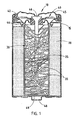
- FIG. 1 shows an electrochemical cell 10 constructed in accordance with a preferred embodiment of the present invention.
- cell 10 includes a cylindrical cell housing 15 in which a positive electrode 20 is located adjacent the inner sidewalls of cell housing 15.
- Positive electrode 20 is shaped as a hollow cylinder that may be impact moulded inside of housing 15 or inserted as a plurality of rings after moulding.
- positive electrode 20 is made primarily of MnO 2 .
- Cell 10 further includes a separator 25 that lines the inner walls of the hollow cavity within positive electrode 20.
- a negative electrode 30 is deposited within the separator-lined hollow cavity of positive electrode 20.
- An alkaline electrolyte, such as KOH, is also dispensed within the lined hollow cavity of positive electrode 20.
- collector assembly 40 includes an inner cover 42, a seal 44, and a current collector 46.
- collector assembly 40 and outer terminal cover 45 are electrically coupled to negative electrode 30 and are insulated from the remainder of cell housing 15. In this manner, outer terminal cover 45 may serve as a negative contact terminal for cell 10.
- a second outer terminal cover 48 may be secured to a closed end 49 of the electrically conductive cell housing 15 to serve as a positive terminal for cell 10.
- negative electrode 30 includes a plurality of ribbons 35 of electrochemically active material.
- the ribbons 35 are elongated flexible elements with a width substantially greater than its thickness and a length substantially greater than its width.
- ribbons 35 are made of zinc, more preferably of a zinc alloy including one or more of the metals selected from bismuth, indium, calcium, and aluminium.
- ribbons 35 have a length that exceeds the radial distance between current collector 46 and the inner surface of separator 25, and preferably have lengths that are at least about 10 times the radial distance between current collector 46 and the inner surface of separator 25 to ensure that the ribbons will extend near the separator interface and still physically contact current collector 46.
- the zinc ribbons maintain a direct electrical connection.
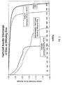
- a half-cell was used to characterise the discharge characteristics of the zinc ribbon.
- the half-cell used was a three-electrode electrochemical system consisting of a working electrode, a cylindrical nickel-mesh counter electrode, and a commercial Hg/HgO reference electrode.
- the working electrode was a cylindrical nylon-mesh basket filled with anode material, either gelled zinc powder or flakes, or zinc ribbon in accordance with the present invention, in contact with a brass nail current collector.
- the half-cell was flooded with electrolyte of a composition of 37 percent KOH/3 percent ZnO. Discharges were conducted at ambient temperature. A constant current was delivered by a Solartron Electrochemical Interface, and electrode potentials were monitored by a data logger. The results are shown in Figure 2.
- the theoretical discharge capacity of zinc is 820 mAh/g.
- the discharge capacity of a half-cell including a negative electrode constructed in accordance with the present invention was found to be approximately 730 mAh/g at a high-rate discharge current of 250 mA per gram of zinc, representing a discharge efficiency of 88.9 percent of the theoretical discharge capacity.
- the high-rate discharge capacity for a half-cell including a conventional zinc negative electrode formed by mixing zinc powder with electrolyte and a gelling agent is 336 mAh/g when discharged at 250 mA per gram of zinc, representing a discharge efficiency of 41 percent of the theoretical discharge capacity for zinc.
- a negative electrode formed using 90 percent zinc powder and 10 percent zinc flakes as taught in WO-A-98/20569 has a discharge capacity of 541 mAh/g at a discharge rate of 250 mA per gram of zinc, representing a discharge efficiency of 66 percent.
- the increased discharge efficiency of the zinc negative electrode of the present invention results in an electrochemical cell having significantly improved high-rate service, which is becoming increasingly important as more and more battery-powered devices are designed that draw current at increasingly higher rates.
Landscapes
- Chemical & Material Sciences (AREA)
- Chemical Kinetics & Catalysis (AREA)
- Electrochemistry (AREA)
- General Chemical & Material Sciences (AREA)
- Engineering & Computer Science (AREA)
- Manufacturing & Machinery (AREA)
- Battery Electrode And Active Subsutance (AREA)
- Primary Cells (AREA)
- Electrolytic Production Of Non-Metals, Compounds, Apparatuses Therefor (AREA)
Claims (8)
- Pile électrochimique comprenant:dans laquelle l'électrode négative comprend au moins un ruban de zinc ou d'alliage de zinc ayant une longueur d'au moins 2 mm, ledit ruban ayant une largeur égale à au moins trois fois son épaisseur et une longueur égale à au moins trois fois sa largeur.un boítier de pile présentant une surface intérieure;une électrode positive disposée adjacente à la surface intérieure du boítier de pile, l'électrode positive définissant une cavité;une électrode négative disposée à l'intérieur de la cavité;un séparateur disposé entre les électrodes positive et négative; etun électrolyte disposé dans le boítier de pile,
- Pile électrochimique selon la revendication 1 et comprenant en outre un collecteur de courant s'étendant centralement à l'intérieur du boítier de pile, dans laquelle le ruban a une longueur au moins égale à la distance entré le séparateur et le collecteur de courant.
- Pile électrochimique selon la revendication 2, dans laquelle le ruban a une longueur d'au moins 10 fois la distance entre le séparateur et le collecteur de courant.
- Pile électrochimique selon l'une quelconque des revendications précédentes, dans laquelle le ruban a une largeur comprise entre 40 et 3200 µm.
- Pile électrochimique selon l'une quelconque des revendications précédentes, dans laquelle le ruban a une épaisseur comprise entre 2 et 80 µm.
- Pile électrochimique selon l'une quelconque des revendications précédentes, dans laquelle le ruban est réalisé à partir d'un alliage de zinc, comprenant au moins un des métaux choisis parmi le bismuth, l'indium, le calcium et l'aluminium.
- Pile électrochimique selon l'une quelconque des revendications précédentes, dans laquelle l'électrolyte est un électrolyte alcalin.
- Pile électrochimique selon l'une quelconque des revendications précédentes, dans laquelle l'électrode positive comprend du MnO2.
Applications Claiming Priority (3)
| Application Number | Priority Date | Filing Date | Title |
|---|---|---|---|
| US203055 | 1998-12-01 | ||
| US09/203,055 US6221527B1 (en) | 1998-12-01 | 1998-12-01 | Electrode for an electrochemical cell including ribbons |
| PCT/US1999/028445 WO2000033405A1 (fr) | 1998-12-01 | 1999-12-01 | Fabrication d'une electrode destinee a une cellule electrochimique |
Publications (2)
| Publication Number | Publication Date |
|---|---|
| EP1138094A1 EP1138094A1 (fr) | 2001-10-04 |
| EP1138094B1 true EP1138094B1 (fr) | 2003-07-02 |
Family
ID=22752294
Family Applications (1)
| Application Number | Title | Priority Date | Filing Date |
|---|---|---|---|
| EP99961903A Expired - Lifetime EP1138094B1 (fr) | 1998-12-01 | 1999-12-01 | Fabrication d'une electrode destinee a une cellule electrochimique |
Country Status (10)
| Country | Link |
|---|---|
| US (1) | US6221527B1 (fr) |
| EP (1) | EP1138094B1 (fr) |
| JP (1) | JP2002531923A (fr) |
| CN (1) | CN1346521A (fr) |
| AT (1) | ATE244456T1 (fr) |
| AU (1) | AU1839100A (fr) |
| CA (1) | CA2352791A1 (fr) |
| DE (1) | DE69909324T2 (fr) |
| HK (1) | HK1040833B (fr) |
| WO (1) | WO2000033405A1 (fr) |
Families Citing this family (10)
| Publication number | Priority date | Publication date | Assignee | Title |
|---|---|---|---|---|
| US6673494B2 (en) | 2002-02-15 | 2004-01-06 | Alltrista Zinc Products, L.P. | Expanded zinc mesh anode |
| US20030170543A1 (en) * | 2002-02-26 | 2003-09-11 | Alltrista Zinc Products Company, L.P. | Zinc fibers, zinc anodes and methods of making zinc fibers |
| US7481851B2 (en) * | 2003-07-03 | 2009-01-27 | The Gillette Company | Alkaline cell with improved anode |
| US7556888B2 (en) * | 2004-02-13 | 2009-07-07 | Eveready Battery Company, Inc. | Electrochemical cell |
| US7291186B2 (en) | 2004-11-01 | 2007-11-06 | Teck Cominco Metals Ltd. | Solid porous zinc electrodes and methods of making same |
| US20080268341A1 (en) * | 2007-03-14 | 2008-10-30 | Teck Cominco Metals Ltd. | High power batteries and electrochemical cells and methods of making same |
| WO2010029679A1 (fr) | 2008-09-12 | 2010-03-18 | パナソニック株式会社 | Pile alcaline sèche sans mercure |
| US20110189517A1 (en) * | 2008-11-21 | 2011-08-04 | Fumio Kato | Alkaline battery |
| WO2010067493A1 (fr) * | 2008-12-12 | 2010-06-17 | パナソニック株式会社 | Pile sèche alcaline |
| JPWO2010067494A1 (ja) * | 2008-12-12 | 2012-05-17 | パナソニック株式会社 | アルカリ乾電池 |
Family Cites Families (12)
| Publication number | Priority date | Publication date | Assignee | Title |
|---|---|---|---|---|
| US3853625A (en) | 1970-04-03 | 1974-12-10 | Union Carbide Corp | Zinc fibers and needles and galvanic cell anodes made therefrom |
| US4012563A (en) * | 1976-03-01 | 1977-03-15 | General Electric Company | Sealed lithium-sodium electrochemical cell with sodium beta-alumina electrolyte |
| IL55412A (en) * | 1978-08-23 | 1982-12-31 | Israel State | Negative electrodes for use in zinc based electrochemical cells |
| DE4015363A1 (de) * | 1990-05-12 | 1991-11-14 | Varta Batterie | Verfahren zur herstellung einer positiven elektrode in bandform fuer primaer- und sekundaerelemente sowie eine vorrichtung fuer dieses verfahren |
| US5856040A (en) | 1991-03-21 | 1999-01-05 | Duracell, Inc. | Alkaline cell |
| JP3317526B2 (ja) * | 1992-08-31 | 2002-08-26 | 日立マクセル株式会社 | アルカリ電池 |
| US5607796A (en) * | 1996-06-24 | 1997-03-04 | Rayovac Corporation | Rechargeable alkaline electrochemical cell |
| JP3527586B2 (ja) * | 1996-04-18 | 2004-05-17 | 松下電器産業株式会社 | アルカリ蓄電池用ニッケル電極の製造法 |
| US6022639A (en) * | 1996-11-01 | 2000-02-08 | Eveready Battery Company, Inc. | Zinc anode for an electochemical cell |
| EP0979533A1 (fr) * | 1997-05-02 | 2000-02-16 | Eveready Battery Company, Inc. | Formes de zinc pour anodes de cellules electrochimiques |
| US6217737B1 (en) | 1997-10-03 | 2001-04-17 | Hirel Connectors Inc. | Method for forming a corrosion-resistant conductive connector shell |
| US6337156B1 (en) * | 1997-12-23 | 2002-01-08 | Sri International | Ion battery using high aspect ratio electrodes |
-
1998
- 1998-12-01 US US09/203,055 patent/US6221527B1/en not_active Expired - Fee Related
-
1999
- 1999-12-01 CN CN99815679A patent/CN1346521A/zh active Pending
- 1999-12-01 CA CA002352791A patent/CA2352791A1/fr not_active Abandoned
- 1999-12-01 AT AT99961903T patent/ATE244456T1/de not_active IP Right Cessation
- 1999-12-01 AU AU18391/00A patent/AU1839100A/en not_active Abandoned
- 1999-12-01 EP EP99961903A patent/EP1138094B1/fr not_active Expired - Lifetime
- 1999-12-01 JP JP2000585950A patent/JP2002531923A/ja not_active Abandoned
- 1999-12-01 DE DE69909324T patent/DE69909324T2/de not_active Expired - Lifetime
- 1999-12-01 WO PCT/US1999/028445 patent/WO2000033405A1/fr active IP Right Grant
-
2002
- 2002-03-27 HK HK02102358.0A patent/HK1040833B/zh not_active IP Right Cessation
Also Published As
| Publication number | Publication date |
|---|---|
| WO2000033405A1 (fr) | 2000-06-08 |
| US6221527B1 (en) | 2001-04-24 |
| DE69909324T2 (de) | 2004-06-03 |
| CN1346521A (zh) | 2002-04-24 |
| EP1138094A1 (fr) | 2001-10-04 |
| CA2352791A1 (fr) | 2000-06-08 |
| HK1040833B (zh) | 2004-04-08 |
| JP2002531923A (ja) | 2002-09-24 |
| HK1040833A1 (en) | 2002-06-21 |
| DE69909324D1 (de) | 2003-08-07 |
| ATE244456T1 (de) | 2003-07-15 |
| AU1839100A (en) | 2000-06-19 |
Similar Documents
| Publication | Publication Date | Title |
|---|---|---|
| AU673925B2 (en) | Alkaline cell | |
| EP1958278B1 (fr) | Pile au manganèse alcaline rechargeable présentant une diminution de capacité réduite et une durée de vie cyclique améliorée | |
| US6361899B1 (en) | Additives for rechargeable alkaline manganese dioxide cells | |
| EP1138094B1 (fr) | Fabrication d'une electrode destinee a une cellule electrochimique | |
| CA2126069C (fr) | Cathodes pour des piles de dioxyde de zinc et de manganese avec du baryum comme additif | |
| EP1218957A1 (fr) | Piles a base de nickel-zinc rechargeables | |
| JPH11500258A (ja) | 二酸化マンガンカソードを有する一次電気化学電池用の添加剤 | |
| US6150052A (en) | Electrode for an electrochemical cell including stacked disks | |
| US3288642A (en) | Rechargeable dry cell having gelled electrolyte | |
| CA1123898A (fr) | Pile electrochimique primaire au lithium et au sulfate de plomb | |
| JP3866903B2 (ja) | アルカリ乾電池 | |
| US6627349B2 (en) | Electrode for an electrochemical cell | |
| US3775273A (en) | Electrolytic process for forming cadmium electrodes | |
| EP0341782A1 (fr) | Méthode de fabrication d'une cellule électrochimique étanche | |
| JPWO2010029678A1 (ja) | 無水銀アルカリ乾電池 | |
| JPH0711957B2 (ja) | 非水二次電池 |
Legal Events
| Date | Code | Title | Description |
|---|---|---|---|
| PUAI | Public reference made under article 153(3) epc to a published international application that has entered the european phase |
Free format text: ORIGINAL CODE: 0009012 |
|
| 17P | Request for examination filed |
Effective date: 20010620 |
|
| AK | Designated contracting states |
Kind code of ref document: A1 Designated state(s): AT BE CH CY DE DK ES FI FR GB GR IE IT LI LU MC NL PT SE |
|
| 17Q | First examination report despatched |
Effective date: 20010919 |
|
| GRAH | Despatch of communication of intention to grant a patent |
Free format text: ORIGINAL CODE: EPIDOS IGRA |
|
| GRAH | Despatch of communication of intention to grant a patent |
Free format text: ORIGINAL CODE: EPIDOS IGRA |
|
| GRAA | (expected) grant |
Free format text: ORIGINAL CODE: 0009210 |
|
| AK | Designated contracting states |
Designated state(s): AT BE CH CY DE DK ES FI FR GB GR IE IT LI LU MC NL PT SE |
|
| PG25 | Lapsed in a contracting state [announced via postgrant information from national office to epo] |
Ref country code: NL Free format text: LAPSE BECAUSE OF FAILURE TO SUBMIT A TRANSLATION OF THE DESCRIPTION OR TO PAY THE FEE WITHIN THE PRESCRIBED TIME-LIMIT Effective date: 20030702 Ref country code: LI Free format text: LAPSE BECAUSE OF FAILURE TO SUBMIT A TRANSLATION OF THE DESCRIPTION OR TO PAY THE FEE WITHIN THE PRESCRIBED TIME-LIMIT Effective date: 20030702 Ref country code: IT Free format text: LAPSE BECAUSE OF FAILURE TO SUBMIT A TRANSLATION OF THE DESCRIPTION OR TO PAY THE FEE WITHIN THE PRESCRIBED TIME-LIMIT;WARNING: LAPSES OF ITALIAN PATENTS WITH EFFECTIVE DATE BEFORE 2007 MAY HAVE OCCURRED AT ANY TIME BEFORE 2007. THE CORRECT EFFECTIVE DATE MAY BE DIFFERENT FROM THE ONE RECORDED. Effective date: 20030702 Ref country code: FI Free format text: LAPSE BECAUSE OF FAILURE TO SUBMIT A TRANSLATION OF THE DESCRIPTION OR TO PAY THE FEE WITHIN THE PRESCRIBED TIME-LIMIT Effective date: 20030702 Ref country code: CH Free format text: LAPSE BECAUSE OF FAILURE TO SUBMIT A TRANSLATION OF THE DESCRIPTION OR TO PAY THE FEE WITHIN THE PRESCRIBED TIME-LIMIT Effective date: 20030702 Ref country code: BE Free format text: LAPSE BECAUSE OF FAILURE TO SUBMIT A TRANSLATION OF THE DESCRIPTION OR TO PAY THE FEE WITHIN THE PRESCRIBED TIME-LIMIT Effective date: 20030702 Ref country code: AT Free format text: LAPSE BECAUSE OF FAILURE TO SUBMIT A TRANSLATION OF THE DESCRIPTION OR TO PAY THE FEE WITHIN THE PRESCRIBED TIME-LIMIT Effective date: 20030702 |
|
| REG | Reference to a national code |
Ref country code: GB Ref legal event code: FG4D |
|
| REG | Reference to a national code |
Ref country code: CH Ref legal event code: EP |
|
| REG | Reference to a national code |
Ref country code: IE Ref legal event code: FG4D |
|
| REF | Corresponds to: |
Ref document number: 69909324 Country of ref document: DE Date of ref document: 20030807 Kind code of ref document: P |
|
| PG25 | Lapsed in a contracting state [announced via postgrant information from national office to epo] |
Ref country code: SE Free format text: LAPSE BECAUSE OF FAILURE TO SUBMIT A TRANSLATION OF THE DESCRIPTION OR TO PAY THE FEE WITHIN THE PRESCRIBED TIME-LIMIT Effective date: 20031002 Ref country code: PT Free format text: LAPSE BECAUSE OF FAILURE TO SUBMIT A TRANSLATION OF THE DESCRIPTION OR TO PAY THE FEE WITHIN THE PRESCRIBED TIME-LIMIT Effective date: 20031002 Ref country code: GR Free format text: LAPSE BECAUSE OF FAILURE TO SUBMIT A TRANSLATION OF THE DESCRIPTION OR TO PAY THE FEE WITHIN THE PRESCRIBED TIME-LIMIT Effective date: 20031002 Ref country code: DK Free format text: LAPSE BECAUSE OF FAILURE TO SUBMIT A TRANSLATION OF THE DESCRIPTION OR TO PAY THE FEE WITHIN THE PRESCRIBED TIME-LIMIT Effective date: 20031002 |
|
| PG25 | Lapsed in a contracting state [announced via postgrant information from national office to epo] |
Ref country code: ES Free format text: LAPSE BECAUSE OF FAILURE TO SUBMIT A TRANSLATION OF THE DESCRIPTION OR TO PAY THE FEE WITHIN THE PRESCRIBED TIME-LIMIT Effective date: 20031013 |
|
| NLV1 | Nl: lapsed or annulled due to failure to fulfill the requirements of art. 29p and 29m of the patents act | ||
| PG25 | Lapsed in a contracting state [announced via postgrant information from national office to epo] |
Ref country code: LU Free format text: LAPSE BECAUSE OF NON-PAYMENT OF DUE FEES Effective date: 20031201 Ref country code: IE Free format text: LAPSE BECAUSE OF NON-PAYMENT OF DUE FEES Effective date: 20031201 Ref country code: CY Free format text: LAPSE BECAUSE OF FAILURE TO SUBMIT A TRANSLATION OF THE DESCRIPTION OR TO PAY THE FEE WITHIN THE PRESCRIBED TIME-LIMIT Effective date: 20031201 |
|
| PG25 | Lapsed in a contracting state [announced via postgrant information from national office to epo] |
Ref country code: MC Free format text: LAPSE BECAUSE OF NON-PAYMENT OF DUE FEES Effective date: 20031231 |
|
| REG | Reference to a national code |
Ref country code: CH Ref legal event code: PL |
|
| ET | Fr: translation filed | ||
| PLBE | No opposition filed within time limit |
Free format text: ORIGINAL CODE: 0009261 |
|
| STAA | Information on the status of an ep patent application or granted ep patent |
Free format text: STATUS: NO OPPOSITION FILED WITHIN TIME LIMIT |
|
| 26N | No opposition filed |
Effective date: 20040405 |
|
| REG | Reference to a national code |
Ref country code: IE Ref legal event code: MM4A |
|
| PGFP | Annual fee paid to national office [announced via postgrant information from national office to epo] |
Ref country code: FR Payment date: 20051216 Year of fee payment: 7 |
|
| REG | Reference to a national code |
Ref country code: FR Ref legal event code: ST Effective date: 20070831 |
|
| PG25 | Lapsed in a contracting state [announced via postgrant information from national office to epo] |
Ref country code: FR Free format text: LAPSE BECAUSE OF NON-PAYMENT OF DUE FEES Effective date: 20070102 |
|
| PGFP | Annual fee paid to national office [announced via postgrant information from national office to epo] |
Ref country code: GB Payment date: 20101229 Year of fee payment: 12 |
|
| PGFP | Annual fee paid to national office [announced via postgrant information from national office to epo] |
Ref country code: DE Payment date: 20111229 Year of fee payment: 13 |
|
| GBPC | Gb: european patent ceased through non-payment of renewal fee |
Effective date: 20121201 |
|
| REG | Reference to a national code |
Ref country code: DE Ref legal event code: R119 Ref document number: 69909324 Country of ref document: DE Effective date: 20130702 |
|
| PG25 | Lapsed in a contracting state [announced via postgrant information from national office to epo] |
Ref country code: DE Free format text: LAPSE BECAUSE OF NON-PAYMENT OF DUE FEES Effective date: 20130702 |
|
| PG25 | Lapsed in a contracting state [announced via postgrant information from national office to epo] |
Ref country code: GB Free format text: LAPSE BECAUSE OF NON-PAYMENT OF DUE FEES Effective date: 20121201 |