EP1137319B1 - Headrest surround channel electroacoustical transducing - Google Patents
Headrest surround channel electroacoustical transducing Download PDFInfo
- Publication number
- EP1137319B1 EP1137319B1 EP01301570A EP01301570A EP1137319B1 EP 1137319 B1 EP1137319 B1 EP 1137319B1 EP 01301570 A EP01301570 A EP 01301570A EP 01301570 A EP01301570 A EP 01301570A EP 1137319 B1 EP1137319 B1 EP 1137319B1
- Authority
- EP
- European Patent Office
- Prior art keywords
- transducers
- electroacoustical
- surround
- channel
- automobile
- Prior art date
- Legal status (The legal status is an assumption and is not a legal conclusion. Google has not performed a legal analysis and makes no representation as to the accuracy of the status listed.)
- Expired - Lifetime
Links
Images


Classifications
-
- H—ELECTRICITY
- H04—ELECTRIC COMMUNICATION TECHNIQUE
- H04R—LOUDSPEAKERS, MICROPHONES, GRAMOPHONE PICK-UPS OR LIKE ACOUSTIC ELECTROMECHANICAL TRANSDUCERS; DEAF-AID SETS; PUBLIC ADDRESS SYSTEMS
- H04R5/00—Stereophonic arrangements
- H04R5/02—Spatial or constructional arrangements of loudspeakers
- H04R5/023—Spatial or constructional arrangements of loudspeakers in a chair, pillow
Definitions
- the invention relates to seat-mounted speakers, and more particularly to surround sound speakers mounted in backs of seats, such as car seats.
- US-A-5 883 961 described a method of synthesizing a set of filters comprises locating first and second loudspeakers at first and second locations, respectively, coupling a first component of an audio program to the first loudspeaker to be reproduced thereby, and coupling a second component of the audio program to the second loudspeaker to be reproduced thereby.
- First and second microphones are placed at third and fourth locations, respectively, at which the reproduced first and second audio components are to be heard in order to convert audio impinging upon the first and second microphones into first and second microphone signals, respectively.
- a first set of transfer functions is developed from the first and second components of the audio program and the first and second microphone signals.
- One loudspeaker is then located at a fifth location different from one of the first and second locations.
- US 3 512 605 discloses a padded headrest which has forwardly extending side wind portions, each of which carries a speaker.
- an automobile audio system comprising: an audio signal source having a plurality of output channels, including a left surround output channel (LS) and a right surround output channel (RS); a first plurality of substantially identical electroacoustical transducers for radiating sound waves corresponding to said left surround channel; and a second plurality of substantially identical electroacoustical transducers for radiating sound waves corresponding to said right surround channel; characterised in that said plurality of electroacoustical transducers are positioned in said passenger compartment such that each of said seats is positioned to locate a passenger's head substantially identically relative to, and in the direct field of, a corresponding one of said first plurality of electroacoustical transducers and to locate a passenger's head substantially identically relative to, and in the direct field of, a corresponding one of said second plurality of electroacoustical transducers wherein an axis of the radiating surface of each electroacoustical transducer is oriented substantially parallel to the longitudinal
- Back of seating device 10 includes two electroacoustical transducers 12, 14 oriented such that their respective axes are substantially vertical.
- the axis of an electroacoustical transducer refers to the axis of the radiating surface, the upper portion of which, also typically points in the primary direction of radiation, especially at high frequencies.
- the axis orientation is taken relative to the back of seating device 10, so that if the back of seating device 10 is reclined, the axis retains its orientation relative to the seat back.
- Electroacoustical transducers 12, 14 receive signals from an audio signal source (not shown) and radiate sound waves representative of the audio signals. Sound waves thus generated can be heard by an occupant of the seating device.
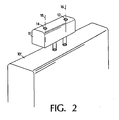
- FIG. 2 there is shown a second embodiment of the seating device and acoustic assembly of FIG 1 .
- electroacoustical transducers 12, 14 are mounted in a headrest 11 attached to seating device 10'.
- Seating devices 10 and 10' can be any one of a variety of devices. Examples include automotive seats, seats for other vehicles, such as trains or aeroplanes, theatre or auditorium seats, home furniture chairs or sofas, or other devices designed for seating which have backs. Electroacoustical transducers 12, 14 are situated such that one transducer is on each side of a user's head when the user is seated in the seating device. This transducer placement facilitates using the transducers for directional audio signals, such as left and right stereophonic signals.
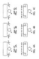
- FIGS. 3A, 3B and 3C there are shown several top views of conventional seat back or head rest mounted transducers, with a user's head 18' at different orientations relative to the transducers. If the axes 20, 22 of the transducers are oriented predominantly forward or inward as shown, a turning of the user's head causes a shift in the orientation of the user's ears relative to the axes of the speakers. This causes a shift in the left - right balance of the sound, a shift that is especially pronounced at high frequencies (at which the sound waves are more directional than at lower frequencies).
- FIGS. 4A, 4B and 4C there are shown several top views of a seat back or headrest mounted transducers according to the invention, with a user's head 18 at different orientations relative to the transducers.
- the axes of transducers do not need to be precisely vertical (that is parallel to the axis of rotation of the user's head 18).
- An orientation that is within ⁇ 20 degrees of vertical will give improved performance over the prior art orientation of FIGS. 3A-3C , wherein the transducers are mounted such that their axes are predominantly sideward or forward relative to the seat back or headrest, and predominantly perpendicular to the axis of rotation of the user's head 18.
- spatial enhancement signal processing is applied to the LS and RS channels before they are radiated by the transducers 12" and 14".
- Spatial enhancement signal processing has the effect of spreading the apparent separation between signal sources in a multi-channel speaker system.
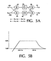
- FIG. 5A there is shown one spatial enhancement signal processing system.
- Left surround input 80L is coupled to first and second summers 82 and 84.
- Right surround input 80R is coupled to first summer 82 and coupled subtractively to second summer 84.
- First summer 82 is coupled to first equalizer 85 which applies a first equalization pattern represented by transfer function G.
- Second summer 84 is coupled to second equalizer 86 which applies a second equalization pattern represented by transfer function H.
- First equalizer 85 is coupled to third summer 88 and fourth summer 90.
- Second equalizer 86 is coupled to third summer 92 and subtractively coupled to fourth summer 90.
- Third summer 88 is coupled to left surround output 92, and fourth summer 90 is coupled to right surround output 94.
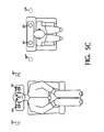
- Transducers 12" and 14" in headrest 11 with spatial enhancement signal processing applied to the signals causes the apparent positions 12"' and 14"' of transducers 12" and 14" to be shifted outward from the listener 18, so that the apparent separation between transducers 12" and 14" is increased, resulting in a sound stage that is wider and more pleasing than without the spatial enhancement signal processing.
- FIG. 6 there is shown a top diagrammatic view of an automobile passenger compartment employing a 5.1 channel surround audio system and seating device and acoustic assemblies according to the invention.
- the passenger compartment In the passenger compartment are four car seats 10 having headrests 11 in which transducers 12, 14 are mounted according to the invention.
- the channels are radiated by transducers positioned about the passenger compartment as follows.
- Centre channel (C) is radiated by a first transducer 20 situated in the dashboard and by second transducer 22 positioned at the rear of a console 24 positioned between the front seats.
- Transducer 22 is oriented such that it radiates sound predominantly toward the rear of the passenger compartment.
- High frequency (above approximately 150 Hz) portions of the left (L) and right (R) channels are radiated by third and fourth transducers 26L and 26R, respectively, positioned on the left and on the right of the dashboard, respectively.
- Low frequency (below approximately 150 Hz) portion of the left and right channels are radiated by fifth and sixth transducers 28L and 28R, respectively, positioned in the left front door and right front door, respectively, forward of the front seats.
- Left and right channel spectral components above approximately 100 Hz are radiated by seventh and eighth transducers 30L and 30R, respectively, positioned in the left rear door and right rear door, respectively, forward of the rear seats.
- Bass which may include the low frequency effects (LFE)
- LFE low frequency effects
- channel is radiated by ninth transducer 32 positioned behind the two rear seats in the package shelf of the passenger compartment and by third and fourth transducers 26L and 26R.
- Left surround channel (LS) is radiated by four transducers 12 in the headrests of the four seats
- right surround channel (RS) is radiated by four transducers 14 in the headrests of the four seats.
- FIG. 7 there is shown a block diagram illustrating the logical arrangement of another feature of the invention.
- Left surround LS input terminal 40 and right surround RS input terminal 42 are coupled to signal processor 44 which is in turn coupled to transducers 12 and 14.
- Other channels (L, R, C) are coupled to other transducers that are positioned about the automobile passenger compartment.
- An example of the placement of other transducers is shown in FIG. 5 , but many other arrangements are possible.
- Also coupled to signal processor 44 are audio input terminals from auxiliary sources, such as car phone input terminal 46, pager input terminal 48, auto-pc input terminal 50, and navigation enunciator 52.
- the signals from input terminals 40 and 42 are transmitted to transducers 12 and 14, and radiated as sound waves by transducers 12 and 14. If there is a signal on one of input terminals 46, 48, 50, or 52 from one of the auxiliary sources, the signal from the auxiliary source is transmitted, and the signals from the left surround input terminal 40 and right surround input terminal 42 are not transmitted so that the seat occupant hears the sound transmitted from the auxiliary source. Alternatively, the signal from the auxiliary source may be transmitted at a higher volume than the surround signals. In a variation of this embodiment, the circuit of FIG. 7 is applied only to the driver's seat, while the transducers in the remaining seats do not receive the signals from the auxiliary sources.
- Fig. 7 represents the logical arrangement of the elements and does not necessarily represent the physical arrangement of the elements.
- An analog implementation may have physical inputs corresponding to the logical inputs 40, 42, 46, 48, 50 and 52, while a digital implementation may have one or more physical inputs combining some or all of the logical inputs 40, 42, 46, 48, 50, and 52.
- Multichannel audio signal source 60 has a number of channel output terminals, including left surround channel output terminal 62 and right surround channel output terminal 64.
- Left surround channel output terminal 62 is coupled to left surround channel equalizer 66 and left surround channel amplifier 68.
- Left surround channel amplifier 68 is coupled to four left surround transducers 12, placed in automobile car seats similar to the four transducers 12' of FIG. 6 .
- right channel output terminal 64 is coupled to right surround channel equalizer 70 and right surround channel amplifier 72.
- Right surround channel amplifier 72 is coupled to four right surround transducers 14, placed in automobile car seats similar to the four transducers 14' of FIG. 6 .
- An audio system according to the embodiment of FIG. 8 is advantageous over conventional automobile audio systems in which the left and right surround channels either use a single pair of transducers to radiate each of the surround channels (which results in the equalization pattern and level being non-optimized for all the individual listening locations) or to use several pairs of transducers and separately equalize and amplify each transducer (which requires additional components and is therefor more complicated and expensive) .
- each occupant of the automobile is in the direct field of a pair of surround transducers; that is, the occupant hears the surround channels primarily from the transducers mounted in the seat, and not from other transducers or from reflections from the automobile interior. Additionally, each occupant is in the same orientation relative to the near-field pair of transducers. Therefore, all the left surround transducers and all the right surround transducers can be equalized according to the same equalization pattern.
- FIG. 8 can also be implemented in audio systems having a single or monophonic surround channel, either by mounting only one transducer in each seat, or by transmitting the single surround channel to both transducers, either in or out of phase.
Description
- The invention relates to seat-mounted speakers, and more particularly to surround sound speakers mounted in backs of seats, such as car seats.
US-A-5 883 961 described a method of synthesizing a set of filters comprises locating first and second loudspeakers at first and second locations, respectively, coupling a first component of an audio program to the first loudspeaker to be reproduced thereby, and coupling a second component of the audio program to the second loudspeaker to be reproduced thereby. First and second microphones are placed at third and fourth locations, respectively, at which the reproduced first and second audio components are to be heard in order to convert audio impinging upon the first and second microphones into first and second microphone signals, respectively. A first set of transfer functions is developed from the first and second components of the audio program and the first and second microphone signals. One loudspeaker is then located at a fifth location different from one of the first and second locations. -
US 3 512 605 discloses a padded headrest which has forwardly extending side wind portions, each of which carries a speaker. - It is an important object of the invention to provide improved surround sound to occupants of seats in environments such as car seats.
- According to the invention, an automobile audio system is provided comprising: an audio signal source having a plurality of output channels, including a left surround output channel (LS) and a right surround output channel (RS); a first plurality of substantially identical electroacoustical transducers for radiating sound waves corresponding to said left surround channel; and a second plurality of substantially identical electroacoustical transducers for radiating sound waves corresponding to said right surround channel; characterised in that said plurality of electroacoustical transducers are positioned in said passenger compartment such that each of said seats is positioned to locate a passenger's head substantially identically relative to, and in the direct field of, a corresponding one of said first plurality of electroacoustical transducers and to locate a passenger's head substantially identically relative to, and in the direct field of, a corresponding one of said second plurality of electroacoustical transducers wherein an axis of the radiating surface of each electroacoustical transducer is oriented substantially parallel to the longitudinal axis of rotation of an occupant's head when occupying said seat.
- Other features, objects, and advantages will become apparent from the following detailed description, which refers to the following drawings in which:
-
FIG. 1 is an isometric view of a seat back according to the invention; -
FIG. 2 is an isometric view of a seatback having a headrest, incorporating the invention; -
FIGS. 3A-3C are top views of a prior art seat mounted speaker system; -
FIGS. 4A-4C are top views of a seat mounted speaker system according to the invention; -
FIG. 5A is a diagrammatic view of a signal processing system according to an aspect of the invention; -
FIG. 5B is a graph of an equalization pattern according to an aspect of the invention; -
FIG. 5C is a diagrammatic view of the psychoacoustic effect of an aspect of the invention; -
FIG. 6 is a diagrammatic view of an automobile audio system incorporating the invention; -
FIG. 7 is a block diagram illustrating the logical arrangement of an aspect of the invention; and -
FIG. 8 is a block diagram illustrating the logical arrangement of an aspect of the invention. - Referring now to the drawings, and particularly to
FIG. 1 , there is shown a seating device and acoustic assembly according to the invention. Back ofseating device 10 includes twoelectroacoustical transducers seating device 10, so that if the back ofseating device 10 is reclined, the axis retains its orientation relative to the seat back.Electroacoustical transducers - Referring now to
FIG. 2 , there is shown a second embodiment of the seating device and acoustic assembly ofFIG 1 . InFIG. 2 ,electroacoustical transducers headrest 11 attached to seating device 10'. -
Seating devices 10 and 10' can be any one of a variety of devices. Examples include automotive seats, seats for other vehicles, such as trains or aeroplanes, theatre or auditorium seats, home furniture chairs or sofas, or other devices designed for seating which have backs.Electroacoustical transducers - Referring to
FIGS. 3A, 3B and 3C , there are shown several top views of conventional seat back or head rest mounted transducers, with a user's head 18' at different orientations relative to the transducers. If theaxes - Referring to
FIGS. 4A, 4B and 4C there are shown several top views of a seat back or headrest mounted transducers according to the invention, with a user'shead 18 at different orientations relative to the transducers. The axes of transducers do not need to be precisely vertical (that is parallel to the axis of rotation of the user's head 18). An orientation that is within ± 20 degrees of vertical will give improved performance over the prior art orientation ofFIGS. 3A-3C , wherein the transducers are mounted such that their axes are predominantly sideward or forward relative to the seat back or headrest, and predominantly perpendicular to the axis of rotation of the user'shead 18. - In one embodiment of the invention, spatial enhancement signal processing is applied to the LS and RS channels before they are radiated by the
transducers 12" and 14". Spatial enhancement signal processing has the effect of spreading the apparent separation between signal sources in a multi-channel speaker system. Referring now toFIG. 5A , there is shown one spatial enhancement signal processing system.Left surround input 80L is coupled to first andsecond summers Right surround input 80R is coupled tofirst summer 82 and coupled subtractively tosecond summer 84.First summer 82 is coupled tofirst equalizer 85 which applies a first equalization pattern represented by transfer function G.Second summer 84 is coupled tosecond equalizer 86 which applies a second equalization pattern represented by transfer function H.First equalizer 85 is coupled tothird summer 88 andfourth summer 90.Second equalizer 86 is coupled tothird summer 92 and subtractively coupled tofourth summer 90.Third summer 88 is coupled toleft surround output 92, andfourth summer 90 is coupled toright surround output 94. The result of the processing of the circuit ofFIG. 5A is

FIG. 5B and where Ls' is the spatially enhanced left surround signal and Rs' is the spatially enhanced right surround signal. If Ls = Rs, there is no cross equalization. - The effect of the spatial enhancement signal processing is illustrated in
FIG. 5C .Transducers 12" and 14" inheadrest 11 with spatial enhancement signal processing applied to the signals causes theapparent positions 12"' and 14"' oftransducers 12" and 14" to be shifted outward from thelistener 18, so that the apparent separation betweentransducers 12" and 14" is increased, resulting in a sound stage that is wider and more pleasing than without the spatial enhancement signal processing. - Referring to
FIG. 6 , there is shown a top diagrammatic view of an automobile passenger compartment employing a 5.1 channel surround audio system and seating device and acoustic assemblies according to the invention. In the passenger compartment are fourcar seats 10 havingheadrests 11 in whichtransducers first transducer 20 situated in the dashboard and bysecond transducer 22 positioned at the rear of aconsole 24 positioned between the front seats.Transducer 22 is oriented such that it radiates sound predominantly toward the rear of the passenger compartment. High frequency (above approximately 150 Hz) portions of the left (L) and right (R) channels are radiated by third andfourth transducers sixth transducers eighth transducers ninth transducer 32 positioned behind the two rear seats in the package shelf of the passenger compartment and by third andfourth transducers transducers 12 in the headrests of the four seats, and right surround channel (RS) is radiated by fourtransducers 14 in the headrests of the four seats. - Referring now to
FIG. 7 , there is shown a block diagram illustrating the logical arrangement of another feature of the invention. Left surroundLS input terminal 40 and right surroundRS input terminal 42 are coupled to signalprocessor 44 which is in turn coupled totransducers FIG. 5 , but many other arrangements are possible. Also coupled to signalprocessor 44 are audio input terminals from auxiliary sources, such as carphone input terminal 46,pager input terminal 48, auto-pc input terminal 50, andnavigation enunciator 52. If there are no signals oninput terminals input terminals transducers transducers input terminals surround input terminal 40 and rightsurround input terminal 42 are not transmitted so that the seat occupant hears the sound transmitted from the auxiliary source. Alternatively, the signal from the auxiliary source may be transmitted at a higher volume than the surround signals. In a variation of this embodiment, the circuit ofFIG. 7 is applied only to the driver's seat, while the transducers in the remaining seats do not receive the signals from the auxiliary sources.Fig. 7 represents the logical arrangement of the elements and does not necessarily represent the physical arrangement of the elements. An analog implementation may have physical inputs corresponding to thelogical inputs logical inputs - Referring to
FIG. 8 there is shown a logical arrangement of elements of an automobile audio system according to another aspect of the invention. Multichannelaudio signal source 60 has a number of channel output terminals, including left surroundchannel output terminal 62 and right surroundchannel output terminal 64. Left surroundchannel output terminal 62 is coupled to leftsurround channel equalizer 66 and leftsurround channel amplifier 68. Leftsurround channel amplifier 68 is coupled to fourleft surround transducers 12, placed in automobile car seats similar to the four transducers 12' ofFIG. 6 . Similarly, rightchannel output terminal 64 is coupled to rightsurround channel equalizer 70 and rightsurround channel amplifier 72. Rightsurround channel amplifier 72 is coupled to fourright surround transducers 14, placed in automobile car seats similar to the four transducers 14' ofFIG. 6 . - An audio system according to the embodiment of
FIG. 8 is advantageous over conventional automobile audio systems in which the left and right surround channels either use a single pair of transducers to radiate each of the surround channels (which results in the equalization pattern and level being non-optimized for all the individual listening locations) or to use several pairs of transducers and separately equalize and amplify each transducer (which requires additional components and is therefor more complicated and expensive) . Referring again toFIGS. 4 and6 , in a sound system in accordance with this aspect of invention, each occupant of the automobile is in the direct field of a pair of surround transducers; that is, the occupant hears the surround channels primarily from the transducers mounted in the seat, and not from other transducers or from reflections from the automobile interior. Additionally, each occupant is in the same orientation relative to the near-field pair of transducers. Therefore, all the left surround transducers and all the right surround transducers can be equalized according to the same equalization pattern. - The embodiment of
FIG. 8 can also be implemented in audio systems having a single or monophonic surround channel, either by mounting only one transducer in each seat, or by transmitting the single surround channel to both transducers, either in or out of phase.
Claims (3)
- An automobile audio system for an automobile having a passenger compartment having at least two seats (10) positioned side-by-side, said audio system comprising:an audio signal source having a plurality of output channels, including a left surround output channel (LS) and a right surround output channel (RS);a first plurality of substantially identical electroacoustical transducers (12) for radiating sound waves corresponding to said left surround channel; anda second plurality of substantially identical electroacoustical transducers (14) for radiating sound waves corresponding to said right surround channel;characterised in that said plurality of electroacoustical transducers (12,14) are positioned in said passenger compartment such that each of said seats (10) is positioned to locate a passenger's head substantially identically relative to, and in the direct field of, a corresponding one of said first plurality of electroacoustical transducers (12) and to locate a passenger's head substantially identically relative to, and in the direct field of, a corresponding one of said second plurality of electroacoustical transducers (14) wherein an axis of the radiating surface of each electroacoustical transducer is oriented substantially parallel to the longitudinal axis of rotation of an occupant's head when occupying said seat.
- An automobile sound system in accordance with claim 1, wherein said first plurality of electroacoustical transducers (12) are each coupled to said audio signal source by a single equalizer (66).
- An automobile sound system in accordance with claim 1 or claim 2, wherein said second plurality of electroacoustical transducers (14) are each coupled to said audio signal source by a single second equalizer (70).
Applications Claiming Priority (2)
| Application Number | Priority Date | Filing Date | Title |
|---|---|---|---|
| US532907 | 1990-06-04 | ||
| US09/532,907 US7424127B1 (en) | 2000-03-21 | 2000-03-21 | Headrest surround channel electroacoustical transducing |
Publications (3)
| Publication Number | Publication Date |
|---|---|
| EP1137319A2 EP1137319A2 (en) | 2001-09-26 |
| EP1137319A3 EP1137319A3 (en) | 2003-07-23 |
| EP1137319B1 true EP1137319B1 (en) | 2012-01-04 |
Family
ID=24123690
Family Applications (1)
| Application Number | Title | Priority Date | Filing Date |
|---|---|---|---|
| EP01301570A Expired - Lifetime EP1137319B1 (en) | 2000-03-21 | 2001-02-21 | Headrest surround channel electroacoustical transducing |
Country Status (3)
| Country | Link |
|---|---|
| US (3) | US7424127B1 (en) |
| EP (1) | EP1137319B1 (en) |
| JP (1) | JP2001298788A (en) |
Cited By (1)
| Publication number | Priority date | Publication date | Assignee | Title |
|---|---|---|---|---|
| DE102013007689A1 (en) | 2013-05-03 | 2014-11-06 | Iav Gmbh Ingenieurgesellschaft Auto Und Verkehr | Method for operating an audio system in a vehicle and audio system in a vehicle |
Families Citing this family (43)
| Publication number | Priority date | Publication date | Assignee | Title |
|---|---|---|---|---|
| US7424127B1 (en) * | 2000-03-21 | 2008-09-09 | Bose Corporation | Headrest surround channel electroacoustical transducing |
| US7483539B2 (en) | 2002-11-08 | 2009-01-27 | Bose Corporation | Automobile audio system |
| US7676047B2 (en) | 2002-12-03 | 2010-03-09 | Bose Corporation | Electroacoustical transducing with low frequency augmenting devices |
| US8139797B2 (en) * | 2002-12-03 | 2012-03-20 | Bose Corporation | Directional electroacoustical transducing |
| US7583806B2 (en) * | 2003-06-09 | 2009-09-01 | Bose Corporation | Convertible automobile sound system equalizing |
| JP4154602B2 (en) | 2003-11-27 | 2008-09-24 | ソニー株式会社 | Audio system for vehicles |
| JP4158941B2 (en) * | 2004-05-13 | 2008-10-01 | パイオニア株式会社 | Acoustic system |
| JP4935091B2 (en) | 2005-05-13 | 2012-05-23 | ソニー株式会社 | Sound reproduction method and sound reproduction system |
| US7688992B2 (en) * | 2005-09-12 | 2010-03-30 | Richard Aylward | Seat electroacoustical transducing |
| KR100656957B1 (en) * | 2006-01-10 | 2006-12-14 | 삼성전자주식회사 | Method for widening listening sweet spot and system of enabling the method |
| JP4359779B2 (en) | 2006-01-23 | 2009-11-04 | ソニー株式会社 | Sound reproduction apparatus and sound reproduction method |
| KR101234087B1 (en) * | 2006-02-01 | 2013-02-19 | 소니 주식회사 | Audio reproducing system and method thereof |
| JP4946305B2 (en) | 2006-09-22 | 2012-06-06 | ソニー株式会社 | Sound reproduction system, sound reproduction apparatus, and sound reproduction method |
| JP4841495B2 (en) | 2007-04-16 | 2011-12-21 | ソニー株式会社 | Sound reproduction system and speaker device |
| US8483413B2 (en) * | 2007-05-04 | 2013-07-09 | Bose Corporation | System and method for directionally radiating sound |
| US8724827B2 (en) | 2007-05-04 | 2014-05-13 | Bose Corporation | System and method for directionally radiating sound |
| US9560448B2 (en) * | 2007-05-04 | 2017-01-31 | Bose Corporation | System and method for directionally radiating sound |
| US9100748B2 (en) | 2007-05-04 | 2015-08-04 | Bose Corporation | System and method for directionally radiating sound |
| US20080273724A1 (en) * | 2007-05-04 | 2008-11-06 | Klaus Hartung | System and method for directionally radiating sound |
| US20080273722A1 (en) * | 2007-05-04 | 2008-11-06 | Aylward J Richard | Directionally radiating sound in a vehicle |
| US8325936B2 (en) * | 2007-05-04 | 2012-12-04 | Bose Corporation | Directionally radiating sound in a vehicle |
| US8126187B2 (en) | 2007-10-29 | 2012-02-28 | Bose Corporation | Vehicle audio system including door-mounted components |
| JP2009260524A (en) * | 2008-04-15 | 2009-11-05 | Sony Corp | Speaker system |
| CA2639409A1 (en) * | 2008-09-09 | 2009-05-30 | Luc Riopel | Home theatre cushion |
| US9555890B2 (en) * | 2009-10-02 | 2017-01-31 | Dennis A Tracy | Loudspeaker system |
| US9950793B2 (en) | 2009-10-02 | 2018-04-24 | Dennis A Tracy | Loudspeaker system |
| US8858343B2 (en) * | 2009-11-09 | 2014-10-14 | Igt | Server-based gaming chair |
| EP3866487B1 (en) | 2010-07-30 | 2024-02-14 | Fraunhofer-Gesellschaft zur Förderung der angewandten Forschung e.V. | Vehicle comprising a headrest speaker arrangement |
| WO2012013743A1 (en) | 2010-07-30 | 2012-02-02 | Fraunhofer-Gesellschaft zur Förderung der Angwandten Forschung E.V. | Vehicle with center-rear-speaker |
| US8913777B2 (en) | 2013-02-06 | 2014-12-16 | Bose Corporation | Providing speakers in a vehicle seat |
| US9088842B2 (en) | 2013-03-13 | 2015-07-21 | Bose Corporation | Grille for electroacoustic transducer |
| US9338536B2 (en) * | 2013-05-07 | 2016-05-10 | Bose Corporation | Modular headrest-based audio system |
| US9327628B2 (en) | 2013-05-31 | 2016-05-03 | Bose Corporation | Automobile headrest |
| JP6374153B2 (en) * | 2013-11-19 | 2018-08-15 | クラリオン株式会社 | Headrest device |
| US9699537B2 (en) | 2014-01-14 | 2017-07-04 | Bose Corporation | Vehicle headrest with speakers |
| US9352701B2 (en) | 2014-03-06 | 2016-05-31 | Bose Corporation | Managing telephony and entertainment audio in a vehicle audio platform |
| US9967672B2 (en) | 2015-11-11 | 2018-05-08 | Clearmotion Acquisition I Llc | Audio system |
| US10715895B2 (en) | 2017-04-20 | 2020-07-14 | Dennis A. Tracy | Loudspeaker system |
| CN113039509A (en) * | 2018-11-21 | 2021-06-25 | 谷歌有限责任公司 | Apparatus and method for providing context awareness using position sensors and virtual acoustic modeling |
| JP2023528410A (en) * | 2020-06-01 | 2023-07-04 | ボーズ・コーポレーション | back speaker |
| US11590869B2 (en) | 2021-05-28 | 2023-02-28 | Bose Corporation | Seatback speakers |
| US11647327B2 (en) | 2020-06-01 | 2023-05-09 | Bose Corporation | Backrest speakers |
| WO2022039539A1 (en) * | 2020-08-21 | 2022-02-24 | 박재범 | Chair provided with multi-channel sound system |
Family Cites Families (51)
| Publication number | Priority date | Publication date | Assignee | Title |
|---|---|---|---|---|
| US3512605A (en) * | 1967-08-31 | 1970-05-19 | David D Mccorkle | Stereo speaker headrest for an automobile seat |
| US4042791A (en) * | 1975-02-27 | 1977-08-16 | Murriel L. Wiseman | Stereophonic head rest |
| US3976162A (en) | 1975-04-07 | 1976-08-24 | Lawrence Peska Associates, Inc. | Personal speaker system |
| US4210784A (en) * | 1976-10-04 | 1980-07-01 | Shaymar, Inc. | Speaker system |
| JPS5647197A (en) | 1979-09-26 | 1981-04-28 | Olympus Optical Co Ltd | Car-mounted speaker |
| AT379275B (en) * | 1982-04-20 | 1985-12-10 | Neutrik Ag | STEREOPHONE PLAYBACK IN VEHICLE ROOMS OF MOTOR VEHICLES |
| JPS60107998A (en) * | 1983-11-16 | 1985-06-13 | Nissan Motor Co Ltd | Acoustic device for automobile |
| US5129004A (en) * | 1984-11-12 | 1992-07-07 | Nissan Motor Company, Limited | Automotive multi-speaker audio system with different timing reproduction of audio sound |
| JPS61127299A (en) | 1984-11-26 | 1986-06-14 | Nissan Motor Co Ltd | Acoustic device for vehicle |
| JPS61188243A (en) | 1985-02-14 | 1986-08-21 | Mitsubishi Electric Corp | Vehicle mounted speaker device |
| US4797934A (en) | 1987-08-27 | 1989-01-10 | Hufnagel Fred M | Speaker headrest |
| JPS6478600A (en) | 1987-09-19 | 1989-03-24 | Matsushita Electric Ind Co Ltd | Noise removing device |
| JPH01136844A (en) | 1987-11-24 | 1989-05-30 | Mazda Motor Corp | Sound device for vehicle |
| JPH01202100A (en) | 1988-02-08 | 1989-08-15 | Toyo Tire & Rubber Co Ltd | Acoustic device |
| JPH027699A (en) | 1988-06-24 | 1990-01-11 | Fujitsu Ten Ltd | Acoustic reproducing device with sound field correction function |
| GB2224178A (en) | 1988-10-19 | 1990-04-25 | Kraco Enterprises Inc | Speaker assembly |
| JP2685841B2 (en) | 1988-10-21 | 1997-12-03 | 株式会社日立製作所 | Semiconductor device and neurochip using multi-stage variable conductance circuit |
| JPH02113494U (en) | 1989-01-17 | 1990-09-11 | ||
| US5146507A (en) * | 1989-02-23 | 1992-09-08 | Yamaha Corporation | Audio reproduction characteristics control device |
| JPH0385096A (en) | 1989-08-28 | 1991-04-10 | Pioneer Electron Corp | Speaker system for body sensing acoustic equipment |
| JPH0385095A (en) | 1989-08-28 | 1991-04-10 | Pioneer Electron Corp | Body sensing acoustic equipment |
| JPH0736866B2 (en) * | 1989-11-28 | 1995-04-26 | ヤマハ株式会社 | Hall sound field support device |
| JPH04137897A (en) | 1990-09-28 | 1992-05-12 | Nissan Motor Co Ltd | On-vehicle acoustic equipment |
| JPH04325338A (en) | 1991-04-26 | 1992-11-13 | Matsushita Electric Ind Co Ltd | Acoustic reproducing device for vehicle |
| KR940005196B1 (en) | 1991-07-03 | 1994-06-13 | 삼성전관 주식회사 | Fluorescent substance based on zinc sulphide |
| US5251260A (en) * | 1991-08-07 | 1993-10-05 | Hughes Aircraft Company | Audio surround system with stereo enhancement and directivity servos |
| US5243640A (en) * | 1991-09-06 | 1993-09-07 | Ford Motor Company | Integrated cellular telephone and vehicular audio system |
| JPH05191342A (en) | 1992-01-17 | 1993-07-30 | Mazda Motor Corp | On-vehicle acoustic device |
| DE4300848A1 (en) | 1992-01-17 | 1993-08-12 | Pioneer Electronic Corp | Car telephone system connected to car radio - transmits telephone signals to car radio for replay over loudspeaker and display on radio display |
| KR960001089Y1 (en) | 1993-01-12 | 1996-02-07 | 조철수 | Frame of multi-functional headrest for a car-seat |
| US5754664A (en) * | 1993-09-09 | 1998-05-19 | Prince Corporation | Vehicle audio system |
| JPH07264689A (en) | 1994-03-16 | 1995-10-13 | Fujitsu Ten Ltd | Headrest speaker |
| JPH07281975A (en) | 1994-04-06 | 1995-10-27 | Hitachi Ltd | Data transmission/reception buffer busy retry method |
| DE4419079C1 (en) * | 1994-05-31 | 1995-11-16 | Kolb Alfred | Close field loudspeaker system |
| JPH08315404A (en) | 1995-05-18 | 1996-11-29 | Sony Corp | Optical pickup device |
| JPH08331682A (en) | 1995-05-29 | 1996-12-13 | Onkyo Corp | On-vehicle stereo reproducing device |
| JPH0970100A (en) | 1995-08-31 | 1997-03-11 | Matsushita Electric Ind Co Ltd | Sound field controller |
| WO1997016048A1 (en) | 1995-10-20 | 1997-05-01 | C.R.F. Societa' Consortile Per Azioni | Sound reproduction system for vehicles |
| CA2240592C (en) | 1996-01-26 | 2003-01-21 | Harman International Industries, Incorporated | Sound system |
| JPH09252499A (en) | 1996-03-14 | 1997-09-22 | Mitsubishi Electric Corp | Multi-channel sound reproducing device |
| US5887071A (en) | 1996-08-07 | 1999-03-23 | Harman International Industries, Incorporated | Dipole speaker headrests |
| US5765314A (en) * | 1996-10-03 | 1998-06-16 | Giglio; Vincent S. | Sensory interactive multi media entertainment theater |
| JPH10194049A (en) | 1997-01-09 | 1998-07-28 | Takeo Naganuma | Holding device of receiving speaker |
| US5742691A (en) * | 1997-02-21 | 1998-04-21 | Ambourn; Paul R. | Surround sound converter |
| FR2768099B1 (en) | 1997-09-05 | 1999-11-05 | Faure Bertrand Equipements Sa | VEHICLE SEAT WITH LOUDSPEAKERS |
| FR2768100B1 (en) | 1997-09-05 | 1999-11-19 | Faure Bertrand Equipements Sa | HEADREST HAVING AT LEAST ONE SPEAKER, VEHICLE SEAT HAVING SUCH A HEADREST, AND AUDIO ASSEMBLY INCLUDING SUCH A HEADREST |
| JP3513850B2 (en) | 1997-11-18 | 2004-03-31 | オンキヨー株式会社 | Sound image localization processing apparatus and method |
| JP3042681B2 (en) | 1998-04-15 | 2000-05-15 | 怡利電子工業股▲ひん▼有限公司 | A handset that does not need to be gripped by a mobile phone combined with the speaker of a car audio system |
| FR2779313B1 (en) | 1998-05-27 | 2002-12-13 | Cyril Patrice Mougeot | DEVICE FOR SOUNDING ARMCHAIRS FOR CREATING A SOUND SOURCE ADDITIVE TO ITS CONVENTIONAL |
| US7424127B1 (en) * | 2000-03-21 | 2008-09-09 | Bose Corporation | Headrest surround channel electroacoustical transducing |
| US7561706B2 (en) * | 2004-05-04 | 2009-07-14 | Bose Corporation | Reproducing center channel information in a vehicle multichannel audio system |
-
2000
- 2000-03-21 US US09/532,907 patent/US7424127B1/en not_active Expired - Fee Related
-
2001
- 2001-02-21 EP EP01301570A patent/EP1137319B1/en not_active Expired - Lifetime
- 2001-03-21 JP JP2001079765A patent/JP2001298788A/en active Pending
-
2006
- 2006-12-21 US US11/614,379 patent/US8098875B2/en not_active Expired - Fee Related
- 2006-12-21 US US11/614,356 patent/US7899198B2/en not_active Expired - Lifetime
Cited By (2)
| Publication number | Priority date | Publication date | Assignee | Title |
|---|---|---|---|---|
| DE102013007689A1 (en) | 2013-05-03 | 2014-11-06 | Iav Gmbh Ingenieurgesellschaft Auto Und Verkehr | Method for operating an audio system in a vehicle and audio system in a vehicle |
| DE102013007689B4 (en) * | 2013-05-03 | 2016-01-21 | Iav Gmbh Ingenieurgesellschaft Auto Und Verkehr | Method for operating an audio system in a vehicle and audio system in a vehicle |
Also Published As
| Publication number | Publication date |
|---|---|
| EP1137319A3 (en) | 2003-07-23 |
| US8098875B2 (en) | 2012-01-17 |
| JP2001298788A (en) | 2001-10-26 |
| EP1137319A2 (en) | 2001-09-26 |
| US20070098205A1 (en) | 2007-05-03 |
| US7424127B1 (en) | 2008-09-09 |
| US20070092100A1 (en) | 2007-04-26 |
| US7899198B2 (en) | 2011-03-01 |
Similar Documents
| Publication | Publication Date | Title |
|---|---|---|
| EP1137319B1 (en) | Headrest surround channel electroacoustical transducing | |
| EP1596627B1 (en) | Reproducing center channel information in a vehicle multichannel audio system | |
| US5887071A (en) | Dipole speaker headrests | |
| EP2987340B1 (en) | Signal processing for a headrest-based audio system | |
| US9330653B2 (en) | Noise reduction apparatus and audio reproduction apparatus | |
| US3512605A (en) | Stereo speaker headrest for an automobile seat | |
| US7343020B2 (en) | Vehicle audio system with directional sound and reflected audio imaging for creating a personal sound stage | |
| EP2172058B1 (en) | System and method for directionally radiating sound | |
| CN110662138A (en) | Modular headrest-based audio system | |
| US20030021433A1 (en) | Speaker configuration and signal processor for stereo sound reproduction for vehicle and vehicle having the same | |
| EP1504549B1 (en) | Discrete surround audio system for home and automotive listening | |
| CA2240592C (en) | Sound system | |
| JPH11318000A (en) | Sound image localization device in cabin | |
| EP1280377A1 (en) | Speaker configuration and signal processor for stereo sound reproduction for vehicle and vehicle having the same | |
| JPH10224887A (en) | On-vehicle speaker system | |
| EP1460879A2 (en) | Individual sound system for vehicles | |
| JPH0946788A (en) | On-vehicle sound reproduction device | |
| US20220078554A1 (en) | Method of providing audio in an automobile, and an audio apparatus for an automobile | |
| US20220286764A1 (en) | Near to the ear subwoofer | |
| JPH04321449A (en) | On-vehicle speaker device and sound reproducing method withit | |
| KR20030000459A (en) | Speaker configuration and signal processor for stereo sound reproduction in a vehicle and a vehicle having the same | |
| JP2003054326A (en) | Speaker arrangement for stereo sound reproduction for vehicle, signal processing machine, and vehicle having the same | |
| MXPA99001297A (en) | Dipole speaker headrests |
Legal Events
| Date | Code | Title | Description |
|---|---|---|---|
| PUAI | Public reference made under article 153(3) epc to a published international application that has entered the european phase |
Free format text: ORIGINAL CODE: 0009012 |
|
| AK | Designated contracting states |
Kind code of ref document: A2 Designated state(s): AT BE CH CY DE DK ES FI FR GB GR IE IT LI LU MC NL PT SE TR |
|
| AX | Request for extension of the european patent |
Free format text: AL;LT;LV;MK;RO;SI |
|
| RIC1 | Information provided on ipc code assigned before grant |
Free format text: 7H 04R 5/02 A, 7H 04S 1/00 B |
|
| PUAL | Search report despatched |
Free format text: ORIGINAL CODE: 0009013 |
|
| AK | Designated contracting states |
Designated state(s): AT BE CH CY DE DK ES FI FR GB GR IE IT LI LU MC NL PT SE TR |
|
| AX | Request for extension of the european patent |
Extension state: AL LT LV MK RO SI |
|
| 17P | Request for examination filed |
Effective date: 20040113 |
|
| AKX | Designation fees paid |
Designated state(s): DE FR |
|
| 17Q | First examination report despatched |
Effective date: 20071031 |
|
| GRAP | Despatch of communication of intention to grant a patent |
Free format text: ORIGINAL CODE: EPIDOSNIGR1 |
|
| GRAS | Grant fee paid |
Free format text: ORIGINAL CODE: EPIDOSNIGR3 |
|
| GRAA | (expected) grant |
Free format text: ORIGINAL CODE: 0009210 |
|
| AK | Designated contracting states |
Kind code of ref document: B1 Designated state(s): DE FR |
|
| REG | Reference to a national code |
Ref country code: DE Ref legal event code: R096 Ref document number: 60145896 Country of ref document: DE Effective date: 20120301 |
|
| PLBE | No opposition filed within time limit |
Free format text: ORIGINAL CODE: 0009261 |
|
| STAA | Information on the status of an ep patent application or granted ep patent |
Free format text: STATUS: NO OPPOSITION FILED WITHIN TIME LIMIT |
|
| 26N | No opposition filed |
Effective date: 20121005 |
|
| REG | Reference to a national code |
Ref country code: DE Ref legal event code: R097 Ref document number: 60145896 Country of ref document: DE Effective date: 20121005 |
|
| REG | Reference to a national code |
Ref country code: FR Ref legal event code: PLFP Year of fee payment: 16 |
|
| REG | Reference to a national code |
Ref country code: FR Ref legal event code: PLFP Year of fee payment: 17 |
|
| REG | Reference to a national code |
Ref country code: FR Ref legal event code: PLFP Year of fee payment: 18 |
|
| PGFP | Annual fee paid to national office [announced via postgrant information from national office to epo] |
Ref country code: DE Payment date: 20190227 Year of fee payment: 19 |
|
| PGFP | Annual fee paid to national office [announced via postgrant information from national office to epo] |
Ref country code: FR Payment date: 20190225 Year of fee payment: 19 |
|
| REG | Reference to a national code |
Ref country code: DE Ref legal event code: R119 Ref document number: 60145896 Country of ref document: DE |
|
| PG25 | Lapsed in a contracting state [announced via postgrant information from national office to epo] |
Ref country code: DE Free format text: LAPSE BECAUSE OF NON-PAYMENT OF DUE FEES Effective date: 20200901 Ref country code: FR Free format text: LAPSE BECAUSE OF NON-PAYMENT OF DUE FEES Effective date: 20200229 |