EP1137161A2 - Method and system for synchronizing the phase angles of parallel connected inverters - Google Patents
Method and system for synchronizing the phase angles of parallel connected inverters Download PDFInfo
- Publication number
- EP1137161A2 EP1137161A2 EP01302326A EP01302326A EP1137161A2 EP 1137161 A2 EP1137161 A2 EP 1137161A2 EP 01302326 A EP01302326 A EP 01302326A EP 01302326 A EP01302326 A EP 01302326A EP 1137161 A2 EP1137161 A2 EP 1137161A2
- Authority
- EP
- European Patent Office
- Prior art keywords
- phase angle
- master inverter
- inverters
- inverter
- server
- Prior art date
- Legal status (The legal status is an assumption and is not a legal conclusion. Google has not performed a legal analysis and makes no representation as to the accuracy of the status listed.)
- Withdrawn
Links
Images

Classifications
-
- H—ELECTRICITY
- H02—GENERATION; CONVERSION OR DISTRIBUTION OF ELECTRIC POWER
- H02M—APPARATUS FOR CONVERSION BETWEEN AC AND AC, BETWEEN AC AND DC, OR BETWEEN DC AND DC, AND FOR USE WITH MAINS OR SIMILAR POWER SUPPLY SYSTEMS; CONVERSION OF DC OR AC INPUT POWER INTO SURGE OUTPUT POWER; CONTROL OR REGULATION THEREOF
- H02M7/00—Conversion of AC power input into DC power output; Conversion of DC power input into AC power output
- H02M7/42—Conversion of DC power input into AC power output without possibility of reversal
- H02M7/44—Conversion of DC power input into AC power output without possibility of reversal by static converters
- H02M7/48—Conversion of DC power input into AC power output without possibility of reversal by static converters using discharge tubes with control electrode or semiconductor devices with control electrode
- H02M7/493—Conversion of DC power input into AC power output without possibility of reversal by static converters using discharge tubes with control electrode or semiconductor devices with control electrode the static converters being arranged for operation in parallel
Definitions
- the present invention generally relates to methods and system for synchronising the phase angles of parallel connected inverters and, more particularly, to a method and system for transmitting phase angle information between inverters in a parallel connected inverter system to synchronise the phase angles of the inverters.
- An inverter is a device which converts direct current (DC) electricity to alternating current (AC) electricity. Inverters are often used to power AC devices in automobiles. In practice, multiple AC voltage sources are needed to be connected in parallel to meet the higher power output requirements of vehicle devices or loads.
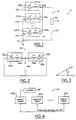
- FIG 1 illustrates an electric system 10 having a plurality of inverters 12a, 12b, and 12n and a load 14.
- Inverters 12 are connected in parallel between one end 18 of load 14 and ground 16. The other end 20 of load 18 is connected to ground 16.
- Each of inverters 12a, 12b, and 12n includes a respective AC voltage source 22a, 22b, and 22n connected to a respective inductance source 24a, 24b, and 24n.
- the voltage vector v i has an associated voltage magnitude and phase angle. The phase angle varies from 0° to 360°.
- AC voltage sources 22 are configured from electronic voltage source inverters (VSIs).
- the phase angle difference among parallel voltage sources can cause circulating real power among these voltage sources.
- the circulating real power reduces the power capability and efficiency of these voltage sources.
- the circulating real power may also cause malfunction of the inverters. To eliminate and minimise the circulating real power it is necessary to eliminate and minimise the phase angle difference between the inverters.
- Figure 2 illustrates a parallel system 30 having two inverters 32a and 32b.
- Each inverter 32 has a respective AC voltage source 34a and 34b and an inductance source 36a and 36b.
- AC voltage sources 34a and 34b provide respective output voltage vectors v 1 and v 2 .
- Figure 3 illustrates the phase angle difference ⁇ between the two voltage vectors v 1 and v 2 . To reduce the circulating real power it is desired to reduce the phase angle difference ⁇ to the smallest value possible.
- the present invention provides a method for transmitting phase angle information between inverters in a parallel connected inverter system to synchronise the phase angles of the inverters.
- the inverter system has a master inverter and a plurality of server inverters connected in parallel. Each inverter has a voltage source. Each of the voltage sources generate a voltage having an associated phase angle which varies as a function of time in a phase cycle.
- the method includes transmitting a common phase angle signal to each of the server inverters.
- the common phase angle signal is a function of the phase angle of the master inverter.
- the common phase angle signal is indicative of the absolute phase angle of the master inverter when the phase angle of the master inverter is equal to a phase angle value associated with a new phase cycle.
- the common phase angle signal is indicative of an incremental phase angle change of the phase angle of the master inverter in a given time period while the phase angle of the master inverter is different from the value associated with a new phase cycle.
- the method preferably further includes controlling the phase angle of each of the server inverters in accordance with the common phase angle signal such that the phase angles of the master inverter and the server inverters are synchronised.
- the phase angle of each of the server inverters is adjusted to be equal to the absolute phase angle of the master inverter when the common phase angle signal is indicative of the absolute phase angle of the master inverter.
- the phase angle of each of the server inverters is adjusted to be equal to the summed value of 1) the incremental phase angle change of the phase angle of the master inverter in the given time period and 2) the phase angle of the respective server inverter prior to the given time period when the common phase angle signal is indicative of the incremental phase angle change of the master inverter.
- the common phase angle signal includes an absolute phase angle data format indicative of the absolute phase angle of the master inverter and an incremental phase angle data format indicative of an incremental phase angle change of the phase angle of the master inverter in a given time period.
- the absolute phase angle data format includes a flag set high and the incremental phase angle data format includes a flag set low.
- the absolute angle data format and the incremental phase angle data format are data bit formats having a fixed amount of data bits.
- the present invention provides an inverter system for carrying out the method of the present invention.
- the inverter system includes a master inverter having a voltage source.
- the voltage source of the master inverter provides a voltage having an associated phase angle which varies as a function of time in a phase cycle.
- the inverter system further includes a plurality of server inverters each having a voltage source. Each of the voltage sources of the server inverters provide a voltage having an associated phase angle which varies as a function of time in a phase cycle.
- the master inverter and the server inverters are connected in parallel.
- the inverter system further includes a controller associated with the master inverter.
- the controller is operable for transmitting a common phase angle signal to each of the server inverters.
- the common phase angle signal is a function of the phase angle of the master inverter.
- the common phase angle signal is indicative of the absolute phase angle of the master inverter when the phase angle of the master inverter is equal to a phase angle value associated with a new phase cycle.
- the common phase angle signal is indicative of an incremental phase angle change of the phase angle of the master inverter in a given time period while the phase angle of the master inverter is different from the value associated with a new phase cycle.
- Inverter system 40 includes a master inverter 42a and a plurality of server inverters 42b and 42n. Inverter system 40 operates such that a common phase angle is used by all inverters 42 to eliminate and minimise any phase angle errors or differences among the inverters.
- Master inverter 42a transmits a common phase angle signal to server inverters 42b and 42n to ensure that all of the inverters have a common phase angle.
- the common phase angle signal is a function of the phase angle of master inverter 42a.
- Server inverters 42b and 42n adjust their phase angles in accordance with the common phase angle signal such that their phase angles are equal to the phase angle of master inverter 42a. This ensures that all of the phase angles of inverters 42 are the same and have no differences.
- Master inverter 42a transmits the common phase angle signal in accordance with the method of the present invention.
- Master inverter 42a transmits the phase angle information (i.e., the common phase angle signal) to server inverters 42b and 42n such that the accuracy of the transmission is guaranteed and the bus width requirement of the transmission is reduced.
- the common phase angle signal is encoded in a data bit format having a plurality of bits.
- Master inverter 42a uses two information transferring formats for the common phase angle signal: 1) an incremental phase angle ⁇ format; and 2) an absolute phase angle ⁇ abs format.
- Figure 5 illustrates a graph 50 of the phase angle of master inverter 42a plotted along the x co-ordinate line 52 versus the AC output voltage of the master inverter plotted along the y co-ordinate line 54.
- the AC output voltage of master inverter 42a cycles periodically as a function of the phase angle.
- the AC output voltage is zero at points 56, 57, and 58.
- the AC output voltage is zero because the phase angle is 0° at point 56, 180° at point 57, and 360° (or 0°) at point 58.
- the AC output voltage varies in a cycle as the phase angle varies from 0° to 360°. After cycling through a cycle the AC output voltage starts the process over by cycling through a new cycle.
- Figure 6 illustrates a graph 60 of time plotted along the x co-ordinate line 62 versus the phase angle of master inverter 42a plotted along the y co-ordinate line 64. At points 65 and 66 the phase angle of master inverter 42a is equal to 0°. From point 65 the phase angle increases from 0° until reaching 360° at point 66.
- Master inverter 42a includes a controller 44 which updates the phase angle of the master inverter in a fixed period of time ⁇ t update . Controller 44 also updates the amount of the phase angle that the AC output voltage of master inverter 42a changes in the update time period ⁇ t update .
- the change in the phase angle is the incremental phase angle ⁇ i .
- the incremental phase angle ⁇ i is determined for each update time period ⁇ t update .
- the plot of graph 60 has step like plots of the phase angle of master inverter 42a because the update time periods are discrete values. As the update time period ⁇ t update gets smaller the plot of the time versus phase angle in graph 60 becomes smoother and less step like.
- the absolute phase angle ⁇ i is the phase angle of the AC output voltage of master inverter 42a at the time t i .
- the absolute phase angle ⁇ i is also the accumulated value of the incremental phase angle ⁇ i over time from 0°.
- the absolute phase angle ⁇ i is 0° at the beginning of each cycle of the AC output voltage.
- Controller 44 of master inverter 42a transmits a common phase angle signal to each of server inverters 42b and 42n for each update time period ⁇ t update .
- Controller 44 transmits a common phase angle signal indicative of the absolute phase angle ⁇ i of master inverter 42a when the phase angle of the master inverter is equal to a phase angle value associated with a new phase cycle.
- This common phase angle signal is in the absolute phase angle format.
- the common phase angle signal is indicative of ⁇ 0 (0 ⁇ ⁇ 0 ⁇ 2 ⁇ f* ⁇ t update ).
- Controller 44 transmits a common phase angle signal indicative of an incremental phase angle change of the phase angle of master inverter 42a in a time update period while the phase angle of the master inverter is different from the phase angle value associated with a negative phase cycle.
- This common phase angle signal is in the incremental angle change format.
- the common phase angle signal is indicative of the change of the phase angle of the master inverter in the time update period.
- Figure 7 illustrates a graph 70 of the time plotted along the x co-ordinate line 72 versus the AC output voltage of master inverter 42a plotted along the y co-ordinate line 74.
- controller 44 transmits the common phase angle signal indicative of the absolute phase angle of master inverter 42a.
- controller 42a transmits the common phase angle signal indicative of the incremental phase angle change of master inverter 42a.
- Figure 8 illustrates a graph 80 of the time plotted along the x co-ordinate line 82 versus the phase angle of master inverter 42a plotted along the y co-ordinate line 84. As shown, the phase angle of master inverter 42a cycles from 0° to 360° in periodic cycles.
- Each format is a data word having a given number of data bits, for instance, ten data bits.
- the most significant bit is a flag to indicate whether the common phase angle signal is indicative of the incremental or absolute phase angle format. For instance, the most significant bit is set low to indicate that the common phase angle signal is indicative of the incremental phase angle change format. Likewise, the most significant bit is set high to indicate that the common phase angle signal is indicative of the absolute phase angle format.
- the remaining bits of the data word are used for the numeric phase angle data.
- the table shows that there is much better resolution to transmit incremental phase angle information than to transmit absolute phase angle information. There is much better resolution because the data range is greatly reduced.
- the table also implies that the transmitting method of the present invention requires much less data bus width than to only transmit absolute phase angle data for the same phase angle resolution.
- alternating the transferring format to absolute phase angle is necessary to prevent accumulation error due to communication error.
- the method of the present invention proposes to perform the alignment only when the phase angle has just passed 0° which should have a small value, and therefore the accuracy can be improved.
- the absolute phase angle may not be 0° because the update time period of the phase angle may not be aligned with the beginning of the AC output voltage cycle. However, it must be within range of the incremental phase angle because the phase angle has just passed 0° and it only can increase so much per step.
- phase angle among the inverters can be periodically aligned to prevent accumulation error, and also the accuracy of the phase angles can be maintained.
- the incremental phase angle ⁇ is used by each server inverter to update its phase angle.
- f k can be dynamically changed, and the information can be converted into ⁇ k to transfer from the master inverter to the server inverters.
Landscapes
- Engineering & Computer Science (AREA)
- Power Engineering (AREA)
- Inverter Devices (AREA)
- Supply And Distribution Of Alternating Current (AREA)
Abstract
Description
| Transmit Format | Data Range (degree) | Phase Angle Resolution ΔΦ (degree) | Note |
| Absolute Phase Angle | 0 to 360 | 0.35156 | Δt = 125 µ-seconds for both cases |
| Incremental Phase Angle Δ | 0 to 2.925 | 0.00286 | For system with maximum frequency 65 Hz, data range = Δt*65*360 |
Claims (10)
- A method for transmitting phase angle information between inverters in a parallel connected inverter system to synchronise the phase angles of the inverters, the inverter system having a master inverter (42a) and a plurality of server inverters (42b-42n) connected in parallel, each inverter having a voltage source, each of the voltage sources generating a voltage having an associated phase angle which varies as a function of time in a phase cycle, the method comprising:
transmitting a common phase angle signal to each of the server inverters (42b-42n), the common phase angle signal being a function of the phase angle of the master inverter (42a), wherein the common phase angle signal is indicative of the absolute phase angle of the master inverter when the phase angle of the master inverter is equal to a phase angle value associated with a new phase cycle, and the common phase angle signal is indicative of an incremental phase angle change of the phase angle of the master inverter (42a) in a given time period while the phase angle of the master inverter is different from the value associated with a new phase cycle. - A method as claimed in claim 1 further comprising:
controlling the phase angle of each of the server inverters in accordance with the common phase angle signal such that the phase angles of the master inverter and the server inverters are synchronised. - A method as claimed in claim 1 further comprising:
adjusting the phase angle of each of the server inverters to be equal to the absolute phase angle of the master inverter when the common phase angle signal is indicative of the absolute phase angle of the master inverter. - A method as claimed in claim 1 further comprising:
adjusting the phase angle of each of the server inverters to be equal to the summed value of 1) the incremental phase angle change of the phase angle of the master inverter in the given time period and 2) the phase angle of the respective server inverter prior to the given time period when the common phase angle signal is indicative of the incremental phase angle change of the master inverter. - A method as claimed in claim 1 wherein:
the common phase angle signal includes an absolute phase angle data format indicative of the absolute phase angle of the master inverter and an incremental phase angle data format indicative of an incremental phase angle change of the phase angle of the master inverter in a given time period, wherein the absolute phase angle data format includes a flag set high and the incremental phase angle data format includes a flag set low. - A method as claimed in claim 5 wherein:
the absolute angle data format and the incremental phase angle data format are data bit formats having a fixed amount of data bits. - An inverter system comprising:a master inverter (42a) having a voltage source, the voltage source of the master inverter providing a voltage having an associated phase angle which varies as a function of time in a phase cycle;a plurality of server inverters (42b-42n) each having a voltage source, each of the voltage sources of the server inverters providing a voltage having an associated phase angle which varies as a function of time in a phase cycle, wherein the master inverter and the server inverters are connected in parallel; anda controller (46) associated with the master inverter, the controller operable for transmitting a common phase angle signal to each of the server inverters, the common phase angle signal being a function of the phase angle of the master inverter,wherein the common phase angle signal is indicative of the absolute phase angle of the master inverter when the phase angle of the master inverter is equal to a phase angle value associated with a new phase cycle, and the common phase angle signal is indicative of an incremental phase angle change of the phase angle of the master inverter in a given time period while the phase angle of the master inverter is different from the value associated with a new phase cycle.
- A system as claimed in claim 7 wherein:
the server inverters adjust their respective phase angles in accordance with the common phase angle signal such that the phase angles of the master inverter and the server inverters are synchronised. - A system as claimed in claim 7 wherein:
the server inverters adjust their phase angles to be equal to the absolute phase angle of the master inverter when the common phase angle signal is indicative of the absolute phase angle of the master inverter. - A system as claimed in claim 7 wherein:
the server inverters adjust their phase angles to be equal to the summed value of 1) the incremental phase angle change of the phase angle of the master inverter in the given time period and 2) the phase angle of the respective server inverter prior to the given time period when the common phase angle signal is indicative of the incremental phase angle change of the master inverter.
Applications Claiming Priority (2)
| Application Number | Priority Date | Filing Date | Title |
|---|---|---|---|
| US532796 | 2000-03-21 | ||
| US09/532,796 US6169679B1 (en) | 2000-03-21 | 2000-03-21 | Method and system for synchronizing the phase angles of parallel connected inverters |
Publications (2)
| Publication Number | Publication Date |
|---|---|
| EP1137161A2 true EP1137161A2 (en) | 2001-09-26 |
| EP1137161A3 EP1137161A3 (en) | 2003-10-22 |
Family
ID=24123206
Family Applications (1)
| Application Number | Title | Priority Date | Filing Date |
|---|---|---|---|
| EP01302326A Withdrawn EP1137161A3 (en) | 2000-03-21 | 2001-03-14 | Method and system for synchronizing the phase angles of parallel connected inverters |
Country Status (3)
| Country | Link |
|---|---|
| US (1) | US6169679B1 (en) |
| EP (1) | EP1137161A3 (en) |
| JP (1) | JP4716394B2 (en) |
Families Citing this family (13)
| Publication number | Priority date | Publication date | Assignee | Title |
|---|---|---|---|---|
| DE10003730A1 (en) * | 2000-01-28 | 2001-08-02 | Bosch Gmbh Robert | Method and device for regulating the parallel operation of DC-DC converters |
| DE10140783A1 (en) * | 2001-08-21 | 2003-04-03 | Inst Solare Energieversorgungstechnik Iset | Device for the parallel operation of single or three-phase voltage sources |
| CN1228908C (en) * | 2001-12-31 | 2005-11-23 | 艾默生网络能源有限公司 | Switch synchronization method of parallel converter system. |
| CN1215636C (en) * | 2001-12-31 | 2005-08-17 | 艾默生网络能源有限公司 | Method of establishing host machine in multi-module parallel system |
| US7142140B2 (en) | 2004-07-27 | 2006-11-28 | Silicon Laboratories Inc. | Auto scanning ADC for DPWM |
| US7518894B2 (en) * | 2005-03-31 | 2009-04-14 | Silicon Laboratories Inc. | Distributed power supply system having reassignable master |
| US8120935B2 (en) * | 2011-03-29 | 2012-02-21 | American Superconductor Corporation | Power converter with dual ring network control |
| KR101590211B1 (en) * | 2011-04-01 | 2016-01-29 | 엘에스산전 주식회사 | Medium voltage inverter |
| CN102231533A (en) * | 2011-06-29 | 2011-11-02 | 阳光电源股份有限公司 | Parallel grid-connected inverter system and switch control method |
| CN103543646B (en) * | 2013-09-24 | 2017-04-05 | 许继集团有限公司 | A kind of equipment balance control method |
| EP2897268B1 (en) | 2014-01-20 | 2022-01-05 | ABB Schweiz AG | Master/slave controller system in ring topology for modular multilevel converters |
| US9800188B2 (en) * | 2015-09-15 | 2017-10-24 | Regal Beloit America, Inc. | Hybrid drive circuit for variable speed induction motor |
| CN105356497B (en) * | 2015-10-23 | 2017-07-07 | 厦门科华恒盛股份有限公司 | Main machine round-robin control method of parallel photovoltaic inverter |
Family Cites Families (12)
| Publication number | Priority date | Publication date | Assignee | Title |
|---|---|---|---|---|
| US3675037A (en) | 1971-06-01 | 1972-07-04 | Bell Telephone Labor Inc | Technique for synchronous parallel operation of static inverters |
| US3832622A (en) * | 1973-07-11 | 1974-08-27 | Avionic Instr Inc | Parallel phase lock circuitry for inverters and the like |
| DE2904786C2 (en) | 1979-02-08 | 1981-02-19 | Siemens Ag, 1000 Berlin Und 8000 Muenchen | Process for regulating inverters in parallel operation and circuit arrangements for carrying out the process |
| US4565953A (en) | 1984-07-02 | 1986-01-21 | General Electric Company | Twelve pulse AC motor drive |
| IT1185262B (en) * | 1985-07-16 | 1987-11-04 | Italtel Spa | CIRCUIT PROVISION FOR THE SYNCHRONIZATION OF A POWER SUPPLY UNIT COMPLEX |
| GB8817684D0 (en) * | 1988-07-25 | 1988-09-01 | Astec Int Ltd | Power factor improvement |
| JP2685586B2 (en) * | 1989-06-30 | 1997-12-03 | 株式会社日立製作所 | Multiple inverter device |
| US5225973A (en) | 1990-09-13 | 1993-07-06 | Sunil Patel | Regulation circuit for a stepped-waveform inverter |
| JPH04190633A (en) * | 1990-11-21 | 1992-07-09 | Hitachi Ltd | Inverter parallel operation method and parallel operation inverter device |
| US5257180A (en) | 1991-04-22 | 1993-10-26 | Mitsubishi Denki Kabushiki Kaisha | Controlling system for parallel operation of AC output inverters with restrained cross currents |
| JP3221807B2 (en) * | 1994-11-18 | 2001-10-22 | 株式会社三社電機製作所 | Inverter parallel operation device |
| US5745356A (en) * | 1996-06-25 | 1998-04-28 | Exide Electronics Corporation | Independent load sharing of AC power systems connected in parallel |
-
2000
- 2000-03-21 US US09/532,796 patent/US6169679B1/en not_active Expired - Lifetime
-
2001
- 2001-03-14 EP EP01302326A patent/EP1137161A3/en not_active Withdrawn
- 2001-03-19 JP JP2001078687A patent/JP4716394B2/en not_active Expired - Fee Related
Also Published As
| Publication number | Publication date |
|---|---|
| US6169679B1 (en) | 2001-01-02 |
| JP4716394B2 (en) | 2011-07-06 |
| EP1137161A3 (en) | 2003-10-22 |
| JP2001314088A (en) | 2001-11-09 |
Similar Documents
| Publication | Publication Date | Title |
|---|---|---|
| US6169679B1 (en) | Method and system for synchronizing the phase angles of parallel connected inverters | |
| US8836270B2 (en) | Inverter system and communication method | |
| US4516035A (en) | Phase synchronization and control circuit | |
| US8645726B2 (en) | Method and system for load sharing in a multiple power supply system | |
| KR20130012304A (en) | Uninterruptible power supply system and parallel operating method | |
| KR20200115373A (en) | Distributed Control System of Hybrid AC/DC Microgrids | |
| CN101395028B (en) | System for synchronous power supply for line and method therefor | |
| EP1459082B1 (en) | A method for on-line calibration of low accuracy voltage sensor through communication bus | |
| US3211987A (en) | Excitation system for a dynamoelectric machine | |
| HK1040839B (en) | Method and device for operating a bus coupler of a bus of building system engineering | |
| US7372374B2 (en) | Measuring device used in process technology, comprising a central power supply unit | |
| JP2003169470A (en) | Power supply and power supply system | |
| JPH02193530A (en) | Receiving end reverse transmission preventing and controlling device | |
| US4127805A (en) | Device for connecting tuned power transmission line to a.c. network | |
| NL2037352B1 (en) | power converter system | |
| JP6869389B1 (en) | Transmission line current calculation system and current calculation method | |
| JP3811655B2 (en) | Power factor control apparatus and method | |
| JPS62269213A (en) | Reactive power compensating device | |
| JPH0535346A (en) | Automatic power factor adjusting device | |
| JP2005176460A (en) | Uninterruptible power system | |
| WO2005050341A1 (en) | Voltage regulator including controllable transformer | |
| JP2007336689A (en) | Standby-type uninterruptible power supply system | |
| JPS6027044B2 (en) | Reactive power control device | |
| JP2024133778A (en) | Power Supply | |
| JPH03155336A (en) | Generator automatic reactive power control device |
Legal Events
| Date | Code | Title | Description |
|---|---|---|---|
| PUAI | Public reference made under article 153(3) epc to a published international application that has entered the european phase |
Free format text: ORIGINAL CODE: 0009012 |
|
| AK | Designated contracting states |
Kind code of ref document: A2 Designated state(s): AT BE CH CY DE DK ES FI FR GB GR IE IT LI LU MC NL PT SE TR |
|
| AX | Request for extension of the european patent |
Free format text: AL;LT;LV;MK;RO;SI |
|
| PUAL | Search report despatched |
Free format text: ORIGINAL CODE: 0009013 |
|
| AK | Designated contracting states |
Kind code of ref document: A3 Designated state(s): AT BE CH CY DE DK ES FI FR GB GR IE IT LI LU MC NL PT SE TR |
|
| AX | Request for extension of the european patent |
Extension state: AL LT LV MK RO SI |
|
| RAP1 | Party data changed (applicant data changed or rights of an application transferred) |
Owner name: BALLARD POWER SYSTEMS CORPORATION |
|
| 17P | Request for examination filed |
Effective date: 20040330 |
|
| AKX | Designation fees paid |
Designated state(s): DE FR GB |
|
| GRAP | Despatch of communication of intention to grant a patent |
Free format text: ORIGINAL CODE: EPIDOSNIGR1 |
|
| GRAS | Grant fee paid |
Free format text: ORIGINAL CODE: EPIDOSNIGR3 |
|
| STAA | Information on the status of an ep patent application or granted ep patent |
Free format text: STATUS: THE APPLICATION IS DEEMED TO BE WITHDRAWN |
|
| 18D | Application deemed to be withdrawn |
Effective date: 20051001 |