EP1136871A2 - Dispositif d'affichage en couleurs à cristal liquide - Google Patents
Dispositif d'affichage en couleurs à cristal liquide Download PDFInfo
- Publication number
- EP1136871A2 EP1136871A2 EP01200825A EP01200825A EP1136871A2 EP 1136871 A2 EP1136871 A2 EP 1136871A2 EP 01200825 A EP01200825 A EP 01200825A EP 01200825 A EP01200825 A EP 01200825A EP 1136871 A2 EP1136871 A2 EP 1136871A2
- Authority
- EP
- European Patent Office
- Prior art keywords
- liquid crystal
- dye
- color screen
- units
- crystal color
- Prior art date
- Legal status (The legal status is an assumption and is not a legal conclusion. Google has not performed a legal analysis and makes no representation as to the accuracy of the status listed.)
- Withdrawn
Links
Images
Classifications
-
- G—PHYSICS
- G02—OPTICS
- G02F—OPTICAL DEVICES OR ARRANGEMENTS FOR THE CONTROL OF LIGHT BY MODIFICATION OF THE OPTICAL PROPERTIES OF THE MEDIA OF THE ELEMENTS INVOLVED THEREIN; NON-LINEAR OPTICS; FREQUENCY-CHANGING OF LIGHT; OPTICAL LOGIC ELEMENTS; OPTICAL ANALOGUE/DIGITAL CONVERTERS
- G02F1/00—Devices or arrangements for the control of the intensity, colour, phase, polarisation or direction of light arriving from an independent light source, e.g. switching, gating or modulating; Non-linear optics
- G02F1/01—Devices or arrangements for the control of the intensity, colour, phase, polarisation or direction of light arriving from an independent light source, e.g. switching, gating or modulating; Non-linear optics for the control of the intensity, phase, polarisation or colour
- G02F1/13—Devices or arrangements for the control of the intensity, colour, phase, polarisation or direction of light arriving from an independent light source, e.g. switching, gating or modulating; Non-linear optics for the control of the intensity, phase, polarisation or colour based on liquid crystals, e.g. single liquid crystal display cells
- G02F1/133—Constructional arrangements; Operation of liquid crystal cells; Circuit arrangements
- G02F1/1333—Constructional arrangements; Manufacturing methods
- G02F1/1335—Structural association of cells with optical devices, e.g. polarisers or reflectors
- G02F1/1336—Illuminating devices
- G02F1/133617—Illumination with ultraviolet light; Luminescent elements or materials associated to the cell
-
- G—PHYSICS
- G02—OPTICS
- G02F—OPTICAL DEVICES OR ARRANGEMENTS FOR THE CONTROL OF LIGHT BY MODIFICATION OF THE OPTICAL PROPERTIES OF THE MEDIA OF THE ELEMENTS INVOLVED THEREIN; NON-LINEAR OPTICS; FREQUENCY-CHANGING OF LIGHT; OPTICAL LOGIC ELEMENTS; OPTICAL ANALOGUE/DIGITAL CONVERTERS
- G02F1/00—Devices or arrangements for the control of the intensity, colour, phase, polarisation or direction of light arriving from an independent light source, e.g. switching, gating or modulating; Non-linear optics
- G02F1/01—Devices or arrangements for the control of the intensity, colour, phase, polarisation or direction of light arriving from an independent light source, e.g. switching, gating or modulating; Non-linear optics for the control of the intensity, phase, polarisation or colour
- G02F1/13—Devices or arrangements for the control of the intensity, colour, phase, polarisation or direction of light arriving from an independent light source, e.g. switching, gating or modulating; Non-linear optics for the control of the intensity, phase, polarisation or colour based on liquid crystals, e.g. single liquid crystal display cells
- G02F1/133—Constructional arrangements; Operation of liquid crystal cells; Circuit arrangements
- G02F1/1333—Constructional arrangements; Manufacturing methods
- G02F1/1335—Structural association of cells with optical devices, e.g. polarisers or reflectors
-
- C—CHEMISTRY; METALLURGY
- C09—DYES; PAINTS; POLISHES; NATURAL RESINS; ADHESIVES; COMPOSITIONS NOT OTHERWISE PROVIDED FOR; APPLICATIONS OF MATERIALS NOT OTHERWISE PROVIDED FOR
- C09K—MATERIALS FOR MISCELLANEOUS APPLICATIONS, NOT PROVIDED FOR ELSEWHERE
- C09K2323/00—Functional layers of liquid crystal optical display excluding electroactive liquid crystal layer characterised by chemical composition
-
- G—PHYSICS
- G02—OPTICS
- G02F—OPTICAL DEVICES OR ARRANGEMENTS FOR THE CONTROL OF LIGHT BY MODIFICATION OF THE OPTICAL PROPERTIES OF THE MEDIA OF THE ELEMENTS INVOLVED THEREIN; NON-LINEAR OPTICS; FREQUENCY-CHANGING OF LIGHT; OPTICAL LOGIC ELEMENTS; OPTICAL ANALOGUE/DIGITAL CONVERTERS
- G02F1/00—Devices or arrangements for the control of the intensity, colour, phase, polarisation or direction of light arriving from an independent light source, e.g. switching, gating or modulating; Non-linear optics
- G02F1/01—Devices or arrangements for the control of the intensity, colour, phase, polarisation or direction of light arriving from an independent light source, e.g. switching, gating or modulating; Non-linear optics for the control of the intensity, phase, polarisation or colour
- G02F1/13—Devices or arrangements for the control of the intensity, colour, phase, polarisation or direction of light arriving from an independent light source, e.g. switching, gating or modulating; Non-linear optics for the control of the intensity, phase, polarisation or colour based on liquid crystals, e.g. single liquid crystal display cells
- G02F1/133—Constructional arrangements; Operation of liquid crystal cells; Circuit arrangements
- G02F1/1333—Constructional arrangements; Manufacturing methods
- G02F1/1335—Structural association of cells with optical devices, e.g. polarisers or reflectors
- G02F1/13356—Structural association of cells with optical devices, e.g. polarisers or reflectors characterised by the placement of the optical elements
- G02F1/133565—Structural association of cells with optical devices, e.g. polarisers or reflectors characterised by the placement of the optical elements inside the LC elements, i.e. between the cell substrates
Definitions
- the invention relates to a liquid crystal color screen equipped with a light source, a polarizer, a liquid crystal cell, which has two transparent plates between which a liquid crystal material is arranged, the plates each one Wear matrix of electrodes, has a front panel and a photoluminescent Layer.
- Liquid crystal screens are based on the principle that light is an external light source the layer of liquid crystals may or may not happen. The bright and preserved an image is created in dark spots. It is also possible by using color filters To produce liquid crystal color screens. The use of color filters is not very much efficient because a large part of the incident light is absorbed by these color filters. The combination of a polarizer analyzer unit with color filters is also unfavorable, because a large part of the incident light is converted into thermal energy. This Effects result in a reduction in the brightness and energy efficiency of the Liquid crystal color screen.
- Another problem is the limited viewing angle of liquid crystal screens, which is due to the principle of operation and the construction of a liquid crystal screen results.
- a liquid crystal color screen is known from EP 0 889 350 A1, in which a photoluminescent Layer that has an isotropic absorption and a polarized, chromatic Emission, is used instead of a conventional polarizer.
- a photoluminescent Layer between liquid crystal cell and viewer is applied.
- the photoluminescent Layer contains, for example, a polyolefin film, which with a dichroistic fluorophore, preferably poly (phenyleneethynylene) derivatives, is doped.
- the fluorophores described in the patent application mostly have only one low emission quantum efficiency, a low dichroic ratio of parallel Absorption to perpendicular absorption or a short lifespan.
- the invention has for its object an improved liquid crystal color screen with an improved viewing angle and improved light efficiency.
- a liquid crystal color screen equipped with a light source, a polarizer, a liquid crystal cell, which has two transparent plates between which a liquid crystal material is arranged, the plates each one Wear matrix of electrodes, has a front panel and a photoluminescent Layer that contains a dichroically absorbing dye and an isotropically emitting one Contains dye.
- dichroistically absorbing dye and the isotropic emitting dye are linked together.
- An intramolecular transfer of energy from one molecular unit to another can be more effective than an intermolecular energy transfer between two molecules.
- the dichroistically absorbing dye and the isotropically emitting dye is selected by one or more compounds from the group of phenylene units, methylene units, difluoromethylene units, Peptide units, norbornyl units, spiro compounds, pyrazine units, Cyclohexyl units, cyclopentyl units or cyclobutyl units with one another are linked.
- the dichroically absorbing dye have a high Has extinction coefficients at the wavelength emitted by the light source.
- the isotropically emitting dye has a small extinction coefficient at the wavelength absorbed by the dichroistically absorbing dye owns.
- the isotropically emitting dye has a high extinction coefficient at the wavelength emitted by the dichroistically absorbing dye owns
- the isotropically emitting dye is a perylene derivative, contains a laser dye derivative or a stilbene derivative.
- the ⁇ * energy level of these molecules is populated by an energy transfer from the absorber to the emitter.
- the ⁇ * energy level is a few nanometers bathochromically shifted to the dichroistic absorption of the absorber.
- the colored light is then emitted at wavelengths of 400 nm and larger. By varying the isotropically emitting dye, all colors can be achieved.
- dichroically absorbing dye and the isotropic emitting dye in a liquid crystal medium or in an elongated polymer embedded or grown epitaxially on an anisotropic substrate.
- the dye molecules of the photoluminescent layer are on a support in a Preferred direction arranged such that their longitudinal axes are oriented in the same direction.
- the photoluminescent layer and the liquid crystal cell are as possible should be placed close together to prevent parallax.
- the photoluminescent layer has a plurality of parallel strips, has a pixel-shaped structure or a zone-like structure.
- the strips alternately contain a photoluminescent layer with dichroistic absorbent dye and one isotropically emitting in one of the three primary colors Dye. In combination with the grid-shaped electrodes, this becomes a pixel-shaped one Get structure.
- the color liquid crystal display has a color filter between the front panel and the photoluminescent layer.
- Some isotropically emitting dyes such as perylene derivatives, can pass through incident ambient light can be excited. With this suggestion, the contrast of the liquid crystal color display can be degraded. The use of a color filter can prevent this.
- the front panel has a UV mirror on.
- This UV mirror reflects non-absorbed UV light back into the optical system. This protects the viewer from this UV light on the one hand and on the other hand the light efficiency of the liquid crystal color screen is increased by this "recycling".
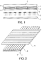
- a liquid crystal color screen has a light source 1 which emits UV light 2.
- the emitted UV light 2 arrives at a polarizer 3 and from there to a liquid crystal cell which has two transparent plates 4 and 5, each of which carries a matrix of electrodes 9, 10.
- the plates 4 and 5, which are made, for example, of glass or a synthetic resin material such as polyester, polycarbonate, polyether sulfone or polyolefin, in particular polynorbornene or polypropylene, can also have an orientation layer made of, for example, polyimide or SiO 2 .
- a liquid crystal material 6 is arranged between the plates 4, 5.
- there is a photoluminescent layer 7 as close as possible to the liquid crystal material 6.
- the liquid crystal material 6 and the photoluminescent layer 7 can have, for example, a stripe-shaped, a pixel-shaped or a zone-like structure.
- the liquid crystal material 6 preferably contains TN (twisted nematic) liquid crystals, since these liquid crystals and thus the TN effect bring about a higher contrast and are independent of the wavelength of the UV light 2.
- It can be liquid crystal materials, cyanobiphenylene, phenylcyclohexanes, Biphenylcyclohexanen or mixtures used p -Alkylbenzyliden- p '-cyanoanilin, p -Alkoxybenzyliden- p' -cyanoanilin from these liquid crystal materials, for example.
- the liquid crystal material 6 can also contain STN (super twisted nematic) liquid crystals, VAN (vertically alligned) liquid crystals or OCB (optically compensated bend) liquid crystals.
- the photoluminescent layer 7 contains a dichroically absorbing dye and an isotropically emitting dye.
- the two dye molecules can also be linked together.
- One or more phenylene units, methylene units, difluoromethylene units, peptide units, norbornyl units, spiro compounds, pyrazine units, cyclohexyl units, cyclopentyl units or cyclobutyl units can act as linking compounds.
- the dichroistically absorbing dye can be, for example, a p- octiphenyl compound.
- This p -octiphenyl compound can be substituted with one or more branched or unbranched alkyl chains.
- the alkyl chains which are for example butyl groups, can additionally be linked to one another.
- the isotropically emitting dye can be, for example, a perylene derivative such as 16,17-dimethoxydinaphtho [1,2,3-cd; 3 ', 2', 1 '-lm] perylene-5,10-dione, dinaphtho [1,2, 3-cd: 3 ', 2', 1'-lm] perylene-5,10-dione, dinaphtho [1,2,3-cd: 1 ', 2', 3'-lm] perylene-9,18- dione or a diimide derived from 3,4,9,10-perylenetetracarboxylic acid.
- the isotropically emitting dye can also be a laser dye such as 2,5-bis (4-biphenylyl) oxazole (BBO), 2- (biphenyl-4-yl) -6-phenylbenzoxazole (PBBO), p- terphenyl, a coumarin Derivative, a phenoxazine dye or a 3,6-bis (alkylamino) -9-phenylxanthylium compound (rhodamine).
- a laser dye such as 2,5-bis (4-biphenylyl) oxazole (BBO), 2- (biphenyl-4-yl) -6-phenylbenzoxazole (PBBO), p- terphenyl, a coumarin Derivative, a phenoxazine dye or a 3,6-bis (alkylamino) -9-phenylxanthylium compound (rhodamine).
- the dye can isotropically emitting butadiene a stilbene derivative such as 4-N, N -Diphenylaminostilben, 1,4-bis (4-N, N -Diphenylaminophenyl), 1,4-bis (4-N, N -Diphenylaminostyryl) benzene, 1,3-bis (4- N , N -diphenylaminostyryl) benzene, 1,4-bis (4- N , N -diphenylaminostyryl) -3,5-dimethoxybenzene, 1,4-bis (4- N , N -Diphenylamino-2'-phenyl-styryl) benzene included.
- the dichroically absorbing dye and the isotropically emitting dye are embedded, for example, in a liquid crystal medium or in an elongated polymer. However, they can also be grown epitaxially on an anisotropic substrate.
- the photoluminescent layer 7 it is also possible for the photoluminescent layer 7 to have a lower layer structure and has upper layer.
- the lower layer which is closer to the light source than that top layer, contains only the dichroistically absorbing dye, which is in a preferred direction embedded in a liquid crystal medium or in an elongated polymer or grown epitaxially on an anisotropic substrate.
- the upper Layer contains the isotropically emitting dye, which is not applied in an oriented manner must become.
- a protective layer or passivation layer prevents alignment of the liquid crystal medium when an electric field is applied to the electrodes 9, 10 or when it is switched off. Another way to prevent this is, the molecules of the liquid crystal medium, after embedding the dichroistic absorbing dye and the isotropically emitting dye to each other network.
- the photoluminescent layer 7 can also be outside the liquid crystal cell are located between the transparent plate 5 and the front plate 8.
- such a liquid crystal color screen can also use active matrix addressing exhibit.
- MIM metal-insulator-metal elements
- TFT thin film transistor
- Fig. 2 is the stripe-shaped structure of the liquid crystal material 6 and the photoluminescent Layer 7 shown. They are also above and below these two Layers of several parallel strip-shaped electrodes 9 and 10.
- the electrodes 9 and 10 are from ITO, for example.
- the principle of operation of a liquid crystal color screen is as follows: One from the light source 1 emitted UV light beam 2 reaches a polarizer 3, which is only light one certain vibration direction passes. The vibration level of the one Liquid crystal of the liquid crystal material 6 striking polarized light beam rotated following the molecular axes as it passes through the cell. Will one When voltage is applied to electrodes 9 and 10, the liquid crystals are aligned in parallel to the electric field. The plane of vibration of polarized light is now not turned more. The UV light then reaches the dichroistically absorbing one Dye which, depending on the polarization direction of the UV light, absorbs it or Not. After absorption, the absorbed energy is isotropic emitting dye. Depending on whether the two dyes together linked or not, the energy transfer takes place intra- or intermolecularly. The isotropically emitting dye emits light with a visible wavelength, which through the front panel 8 to the viewer.
- a liquid crystal color screen had a UV lamp as light source 1, which emitted UV light 2 with a wavelength of 366 nm. Furthermore, the liquid crystal color screen had a polarizer 3.
- the liquid crystal cell of the color liquid crystal panel had a lower transparent plate 4 and an upper transparent plate 5, both of which contained glass.
- Several, parallel, strip-shaped electrodes 9 and 10 made of ITO were applied to the transparent plates 4 and 5. The electrodes 9 were arranged rotated by 90 ° to the electrodes 10.
- a strip-shaped, photoluminescent layer 7 is arranged between the liquid crystal cell and the upper transparent plate 5. Each strip of the photoluminescent layer 7 contained a p -octiphenyl derivative as the dichroistically absorbing dye.
- the entire color liquid crystal display had an improved viewing angle and improved Light efficiency on.
- a liquid crystal color screen had a UV lamp as light source 1, which emitted UV light 2 with a wavelength of 366 nm. Furthermore, the liquid crystal color screen had a polarizer 3.
- the liquid crystal cell of the color liquid crystal panel had a lower transparent plate 4 and an upper transparent plate 5, both of which contained glass.
- Several parallel, strip-shaped electrodes 9 and 10 made of ITO were applied to the transparent plates 4 and 5. The electrodes 9 were arranged rotated by 90 ° to the electrodes 10.
- a strip-shaped, photoluminescent layer 2 is arranged between the liquid crystal cell and the upper transparent plate 5.
- each strip of the photoluminescent layer 7 contained a p -octiphenyl derivative as the dichroistically absorbing dye.
- the dichroistically absorbing dye was linked to an isotropically emitting dye via a methylene group in the 2-position of the first phenyl ring of the p -octiphenyl derivative.
- Dinaphtho [1,2,3-cd: 3 ', 2', 1'-lm] perylene-5,10-dione was used as the blue-emitting dye
- sulforhodamine B as the red-emitting dye
- 16.1 7 as the green-emitting dye -Dimethoxydinaphtho [1,2,3-cd; 3 ', 2', 1'-lm] perylene-5,10-dione was used.
- the color liquid crystal screen included a glass front panel 8.
- the entire liquid crystal color screen had an improved viewing angle and improved light efficiency.
Landscapes
- Physics & Mathematics (AREA)
- Nonlinear Science (AREA)
- Mathematical Physics (AREA)
- Chemical & Material Sciences (AREA)
- Crystallography & Structural Chemistry (AREA)
- General Physics & Mathematics (AREA)
- Optics & Photonics (AREA)
- Liquid Crystal (AREA)
- Devices For Indicating Variable Information By Combining Individual Elements (AREA)
- Polarising Elements (AREA)
Applications Claiming Priority (2)
| Application Number | Priority Date | Filing Date | Title |
|---|---|---|---|
| DE10012326A DE10012326A1 (de) | 2000-03-14 | 2000-03-14 | Flüssigkristall-Farbbildschirm |
| DE10012326 | 2000-03-14 |
Publications (2)
| Publication Number | Publication Date |
|---|---|
| EP1136871A2 true EP1136871A2 (fr) | 2001-09-26 |
| EP1136871A3 EP1136871A3 (fr) | 2004-12-01 |
Family
ID=7634631
Family Applications (1)
| Application Number | Title | Priority Date | Filing Date |
|---|---|---|---|
| EP01200825A Withdrawn EP1136871A3 (fr) | 2000-03-14 | 2001-03-06 | Dispositif d'affichage en couleurs à cristal liquide |
Country Status (6)
| Country | Link |
|---|---|
| US (1) | US6563556B2 (fr) |
| EP (1) | EP1136871A3 (fr) |
| JP (1) | JP2001330824A (fr) |
| KR (1) | KR20010096598A (fr) |
| DE (1) | DE10012326A1 (fr) |
| TW (1) | TWI249631B (fr) |
Families Citing this family (8)
| Publication number | Priority date | Publication date | Assignee | Title |
|---|---|---|---|---|
| EP1552726A2 (fr) * | 2002-10-18 | 2005-07-13 | iFire Technology Corp. | AFFICHAGES EN COULEURs ELECTROLUMINESCENTES |
| US7229726B2 (en) * | 2003-12-02 | 2007-06-12 | E. I. Du Pont De Nemours And Company | Thermal imaging process and products made therefrom |
| CN100504543C (zh) * | 2007-03-06 | 2009-06-24 | 孙润光 | 显示装置以及含有该显示装置的手机、计算机和电视机 |
| KR101386353B1 (ko) * | 2008-05-09 | 2014-04-16 | 칼 짜이스 에스엠티 게엠베하 | 푸리에 광학 시스템을 포함하는 조명 시스템 |
| DE102008023763A1 (de) | 2008-05-09 | 2009-11-12 | Carl Zeiss Smt Ag | Beleuchtungssystem für eine Mikrolithographie-Projektionsbelichtungsanlage, Mikrolithographie-Projektionsbelichtungsanlage mit einem solchen Beleuchtungssystem sowie Fourieroptiksystem |
| DE102008035320A1 (de) | 2008-07-25 | 2010-01-28 | Carl Zeiss Smt Ag | Beleuchtungssystem für eine Mikrolithographie-Projektionsbelichtungsanlage, Mikrolithographie-Projektionsbelichtungsanlage mit einem solchen Beleuchtungssystem sowie Fourieroptiksystem |
| KR101924997B1 (ko) | 2012-07-03 | 2018-12-05 | 삼성디스플레이 주식회사 | 표시 장치 및 그 제조 방법 |
| US10554961B2 (en) * | 2016-11-08 | 2020-02-04 | Kevin Vora | Three-dimensional volumetric display using photoluminescent materials |
Family Cites Families (10)
| Publication number | Priority date | Publication date | Assignee | Title |
|---|---|---|---|---|
| DE2837257A1 (de) * | 1977-04-12 | 1979-03-22 | Sharp Kk | Fluoreszenz-fluessigkristall-anzeigevorrichtung |
| CH638624A5 (de) * | 1978-04-12 | 1983-09-30 | Secr Defence Brit | Elektrooptisches fluessigkristall-anzeigegeraet. |
| US4772885A (en) * | 1984-11-22 | 1988-09-20 | Ricoh Company, Ltd. | Liquid crystal color display device |
| US4822144A (en) * | 1986-12-24 | 1989-04-18 | U.S. Philips Corporation | Electro-optic color display including luminescent layer and interference filter |
| CA1274613A (fr) * | 1986-12-24 | 1990-09-25 | Leendert Vriens | Dispositifs connexes de projection et d'affichage |
| US5800996A (en) * | 1996-05-03 | 1998-09-01 | The Perkin Elmer Corporation | Energy transfer dyes with enchanced fluorescence |
| EP0889350A1 (fr) * | 1997-07-03 | 1999-01-07 | ETHZ Institut für Polymere | Dispositifs d'affichage photoluminescents |
| EP0933655A1 (fr) * | 1998-01-29 | 1999-08-04 | ETHZ Institut für Polymere | Polariseurs photoluminescents efficaces, procédé pour leur fabrication, et leur application à des dispositifs d'affichage |
| DE60027754T2 (de) * | 1999-07-22 | 2007-05-03 | Landqart | Verfahren zur herstellung von photolumineszenten polarisatoren |
| US6295106B1 (en) * | 2000-01-12 | 2001-09-25 | International Business Machines Corporation | Energy-efficient full-color liquid crystal display |
-
2000
- 2000-03-14 DE DE10012326A patent/DE10012326A1/de not_active Withdrawn
-
2001
- 2001-03-06 EP EP01200825A patent/EP1136871A3/fr not_active Withdrawn
- 2001-03-09 US US09/803,333 patent/US6563556B2/en not_active Expired - Fee Related
- 2001-03-12 JP JP2001068058A patent/JP2001330824A/ja active Pending
- 2001-03-12 KR KR1020010012613A patent/KR20010096598A/ko not_active Abandoned
- 2001-03-30 TW TW090107731A patent/TWI249631B/zh not_active IP Right Cessation
Also Published As
| Publication number | Publication date |
|---|---|
| KR20010096598A (ko) | 2001-11-07 |
| US20010033348A1 (en) | 2001-10-25 |
| JP2001330824A (ja) | 2001-11-30 |
| DE10012326A1 (de) | 2001-09-20 |
| EP1136871A3 (fr) | 2004-12-01 |
| TWI249631B (en) | 2006-02-21 |
| US6563556B2 (en) | 2003-05-13 |
Similar Documents
| Publication | Publication Date | Title |
|---|---|---|
| EP0407830B1 (fr) | Polariseur | |
| DE112011100732T5 (de) | Elektrooptisches Schaltelement und elektrooptische Anzeige | |
| DE69613093T2 (de) | Elektrolumineszente vorrichtung | |
| DE69718552T2 (de) | Zweifache PDLC Projektions-Headup-Anzeige | |
| DE69015249T2 (de) | Verfahren zum Herstellen eines Polarisationsfilters und auf diese Weise erhaltenes Polarisationsfilter und eine mit dem Polarisationsfilter versehene Wiedergabeanordnung. | |
| US5473450A (en) | Liquid crystal display device with a polymer between liquid crystal regions | |
| DE69217693T2 (de) | Optisches Flüssigkristallelement, Flüssigkristallanzeigeelement und Flüssigkristall-Projektionsanzeigegerät das dieses Element verwendet | |
| DE69414621T2 (de) | Flüssigkristall-Anzeige mit weitem Sichtwinkel | |
| DE69934500T2 (de) | Transflektives flüssigkristalldisplay | |
| DE2835863C2 (de) | Flüssigkristallanzeige mit FK-Mischung aus einem nematischen Flüssigkristall und einer optisch aktiven Substanz sowie einem pleochroitischen Zusatz | |
| DE3825697C2 (fr) | ||
| DE2046566A1 (de) | Farbwiedergabevorrichtung auf Basis flussiger Kristalle | |
| EP1116988A2 (fr) | Dispositif d'affichage à cristal liquide avec plaque frontale fluorescente | |
| EP0713126A1 (fr) | Affichage coloré comprenant des filtres à cristal liquide contrÔlables électriquement disposés en série | |
| DE69714664T2 (de) | Verdrillt-nematische Flüssigkristallvorrichtung | |
| CH638624A5 (de) | Elektrooptisches fluessigkristall-anzeigegeraet. | |
| CH664027A5 (de) | Fluessigkristallanzeige. | |
| KR100745115B1 (ko) | 액정표시장치 | |
| DE2418364B2 (de) | Elektrooptisches Anzeigeelement mit einem nematischen Flüssigkristallsystem mit positiver dielektrischer Anisotropie | |
| EP1116989A2 (fr) | Affichage couleur à cristal liquide avec couche de matériau luminescent | |
| DE69617508T2 (de) | Farbanzeigevorrichtung | |
| EP0041184A2 (fr) | Cellule d'affichage à cristal liquide et procédé pour sa fabrication | |
| DE10337524A1 (de) | Reflektive Flüssigkristallanzeigevorrichtung mit cholesterischem Flüssigkristallfarbfilter und Verfahren zum Herstellen derselben | |
| DE69211132T2 (de) | Grossflächige flüssigkristallanzeige | |
| EP1136871A2 (fr) | Dispositif d'affichage en couleurs à cristal liquide |
Legal Events
| Date | Code | Title | Description |
|---|---|---|---|
| PUAI | Public reference made under article 153(3) epc to a published international application that has entered the european phase |
Free format text: ORIGINAL CODE: 0009012 |
|
| AK | Designated contracting states |
Kind code of ref document: A2 Designated state(s): AT BE CH CY DE DK ES FI FR GB GR IE IT LI LU MC NL PT SE TR |
|
| AX | Request for extension of the european patent |
Free format text: AL;LT;LV;MK;RO;SI |
|
| RAP1 | Party data changed (applicant data changed or rights of an application transferred) |
Owner name: KONINKLIJKE PHILIPS ELECTRONICS N.V. Owner name: PHILIPS CORPORATE INTELLECTUAL PROPERTY GMBH |
|
| RAP1 | Party data changed (applicant data changed or rights of an application transferred) |
Owner name: KONINKLIJKE PHILIPS ELECTRONICS N.V. Owner name: PHILIPS INTELLECTUAL PROPERTY & STANDARDS GMBH |
|
| PUAL | Search report despatched |
Free format text: ORIGINAL CODE: 0009013 |
|
| AK | Designated contracting states |
Kind code of ref document: A3 Designated state(s): AT BE CH CY DE DK ES FI FR GB GR IE IT LI LU MC NL PT SE TR |
|
| AX | Request for extension of the european patent |
Extension state: AL LT LV MK RO SI |
|
| 17P | Request for examination filed |
Effective date: 20050601 |
|
| AKX | Designation fees paid |
Designated state(s): DE FR GB |
|
| STAA | Information on the status of an ep patent application or granted ep patent |
Free format text: STATUS: THE APPLICATION IS DEEMED TO BE WITHDRAWN |
|
| 18D | Application deemed to be withdrawn |
Effective date: 20060119 |