EP1136858A2 - Dispositif pour varier les caractéristiques optiques d'une fibre optique en l'étirant - Google Patents
Dispositif pour varier les caractéristiques optiques d'une fibre optique en l'étirant Download PDFInfo
- Publication number
- EP1136858A2 EP1136858A2 EP01302023A EP01302023A EP1136858A2 EP 1136858 A2 EP1136858 A2 EP 1136858A2 EP 01302023 A EP01302023 A EP 01302023A EP 01302023 A EP01302023 A EP 01302023A EP 1136858 A2 EP1136858 A2 EP 1136858A2
- Authority
- EP
- European Patent Office
- Prior art keywords
- fiber
- lever part
- base
- fulcrum
- lever
- Prior art date
- Legal status (The legal status is an assumption and is not a legal conclusion. Google has not performed a legal analysis and makes no representation as to the accuracy of the status listed.)
- Withdrawn
Links
Images

Classifications
-
- G—PHYSICS
- G02—OPTICS
- G02B—OPTICAL ELEMENTS, SYSTEMS OR APPARATUS
- G02B6/00—Light guides; Structural details of arrangements comprising light guides and other optical elements, e.g. couplings
- G02B6/02—Optical fibres with cladding with or without a coating
- G02B6/02057—Optical fibres with cladding with or without a coating comprising gratings
- G02B6/02076—Refractive index modulation gratings, e.g. Bragg gratings
- G02B6/02195—Refractive index modulation gratings, e.g. Bragg gratings characterised by means for tuning the grating
- G02B6/022—Refractive index modulation gratings, e.g. Bragg gratings characterised by means for tuning the grating using mechanical stress, e.g. tuning by compression or elongation, special geometrical shapes such as "dog-bone" or taper
-
- G—PHYSICS
- G02—OPTICS
- G02F—OPTICAL DEVICES OR ARRANGEMENTS FOR THE CONTROL OF LIGHT BY MODIFICATION OF THE OPTICAL PROPERTIES OF THE MEDIA OF THE ELEMENTS INVOLVED THEREIN; NON-LINEAR OPTICS; FREQUENCY-CHANGING OF LIGHT; OPTICAL LOGIC ELEMENTS; OPTICAL ANALOGUE/DIGITAL CONVERTERS
- G02F1/00—Devices or arrangements for the control of the intensity, colour, phase, polarisation or direction of light arriving from an independent light source, e.g. switching, gating or modulating; Non-linear optics
- G02F1/01—Devices or arrangements for the control of the intensity, colour, phase, polarisation or direction of light arriving from an independent light source, e.g. switching, gating or modulating; Non-linear optics for the control of the intensity, phase, polarisation or colour
- G02F1/011—Devices or arrangements for the control of the intensity, colour, phase, polarisation or direction of light arriving from an independent light source, e.g. switching, gating or modulating; Non-linear optics for the control of the intensity, phase, polarisation or colour in optical waveguides, not otherwise provided for in this subclass
- G02F1/0115—Devices or arrangements for the control of the intensity, colour, phase, polarisation or direction of light arriving from an independent light source, e.g. switching, gating or modulating; Non-linear optics for the control of the intensity, phase, polarisation or colour in optical waveguides, not otherwise provided for in this subclass in optical fibres
-
- G—PHYSICS
- G02—OPTICS
- G02B—OPTICAL ELEMENTS, SYSTEMS OR APPARATUS
- G02B6/00—Light guides; Structural details of arrangements comprising light guides and other optical elements, e.g. couplings
- G02B6/24—Coupling light guides
- G02B6/26—Optical coupling means
- G02B6/35—Optical coupling means having switching means
- G02B6/3502—Optical coupling means having switching means involving direct waveguide displacement, e.g. cantilever type waveguide displacement involving waveguide bending, or displacing an interposed waveguide between stationary waveguides
-
- G—PHYSICS
- G02—OPTICS
- G02B—OPTICAL ELEMENTS, SYSTEMS OR APPARATUS
- G02B6/00—Light guides; Structural details of arrangements comprising light guides and other optical elements, e.g. couplings
- G02B6/24—Coupling light guides
- G02B6/26—Optical coupling means
- G02B6/35—Optical coupling means having switching means
- G02B6/3564—Mechanical details of the actuation mechanism associated with the moving element or mounting mechanism details
- G02B6/3568—Mechanical details of the actuation mechanism associated with the moving element or mounting mechanism details characterised by the actuating force
- G02B6/3572—Magnetic force
-
- G—PHYSICS
- G02—OPTICS
- G02B—OPTICAL ELEMENTS, SYSTEMS OR APPARATUS
- G02B6/00—Light guides; Structural details of arrangements comprising light guides and other optical elements, e.g. couplings
- G02B6/24—Coupling light guides
- G02B6/36—Mechanical coupling means
- G02B6/3616—Holders, macro size fixtures for mechanically holding or positioning fibres, e.g. on an optical bench
-
- G—PHYSICS
- G02—OPTICS
- G02F—OPTICAL DEVICES OR ARRANGEMENTS FOR THE CONTROL OF LIGHT BY MODIFICATION OF THE OPTICAL PROPERTIES OF THE MEDIA OF THE ELEMENTS INVOLVED THEREIN; NON-LINEAR OPTICS; FREQUENCY-CHANGING OF LIGHT; OPTICAL LOGIC ELEMENTS; OPTICAL ANALOGUE/DIGITAL CONVERTERS
- G02F2201/00—Constructional arrangements not provided for in groups G02F1/00 - G02F7/00
- G02F2201/30—Constructional arrangements not provided for in groups G02F1/00 - G02F7/00 grating
- G02F2201/307—Reflective grating, i.e. Bragg grating
Definitions
- the present invention relates to apparatus for stretching an optical fiber, particularly to alter the optical characteristics of a Bragg grating incorporated in the fiber.
- the stretching may be used to determine whether a light of certain wavelengths passes through the fiber or is reflected by the grating.
- the grating can be tuned to particular wavelengths by stretching the fiber.
- Such a grating comprises a series of periodic variations in the refractive index of the core of the fiber, and is effective to reflect certain wavelengths of light back along the fiber while allowing other wavelengths to pass.
- a device which changes the length of a portion of fiber between precise limits, which limits will preferably be adjustable.
- Such a device can be used to switch the grating between two conditions. For example, in a bistable device, the light which is back reflected from a Bragg grating can be switched between two wavelengths, which can determine whether data is allowed to follow an express throughput path or whether it is back-reflected and re-routed.
- apparatus for modifying the optical characteristics of an optical fiber by controlled stretching of a length of the fiber comprises:
- the first and second fiber holding means will of course be located at portions of the fiber on opposite sides of the Bragg grating.
- the lever preferably provides a considerable mechanical advantage, so that the movement of the outer end of the lever, which is controlled by adjustable stops, produces a much smaller amount of movement in the second, i.e. the movable fiber holding means.
- the length of the lever part between the fulcrum and the electromagnetic means is at least 10 times the distance between the fulcrum and the second fiber holding means.
- the fulcrum may be provided by a flexure which is integral both with the lever part and with a part of said base; this ensures that there is no play at the fulcrum and the movement is substantially frictionless, and energy losses are very small. Also, the lack of bearing surfaces means that this construction has a long life.
- the lever part is releasably held in the first or second positions by magnetic latching means, which positions are determined by adjustable stops.
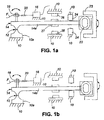
- Fig.1 shows, diagrammatically, the stretcher as comprising a fixed base 10 of metal carrying support 10a which is integrally connected by a thin metal web or flexure 12 to a lever part 14 having a lever arm 14a.
- the base 10 also supports fixed fiber holding means 16, for example a platform to which a portion of fiber F is bonded.
- a second, movable fiber holding means 18 is in the form of an arm movable with, and effectively forming part of, the lever part 14, and is bonded to a second portion of the fiber F.
- the intermediate length of fiber between those portions held by the holding means 16 and 18 has a Bragg grating indicated at 20; this portion of the fiber is held taut at all times and is stretched as the lever arm 14a moves from the Fig.1b position to that of Fig.1a.
- Movement of the lever arm 14a is controlled by a coil 22 mounted for movement on the lever arm within a magnetic field produced by a yoke 23.
- the amount of movement of the lever is controlled by adjustable stops 24 situated at opposite sides of the outer end portion of the lever arm.
- the lever is made bistable in the two positions where it contacts the stops, and is magnetically latched by magnetic latching means in the form of permanent magnets 26 which attract a movable magnet 27 attached to the lever arm; the magnets are adjusted so that they are at all times out of contact with the magnet 27, and do not affect the range of movement of the lever arm.
- this apparatus provides a bistable fiber stretcher which applies two levels of tension to the Bragg grating 20 depending on the position of the lever as determined by the coil 22.
- bistable device i.e. one which latches in either of two stable positions
- the invention is not limited to bistable devices, and with suitable latching mechanism might be used to give three or more stable states to provide a more complex switching pattern for the Bragg grating or other device incorporated in an optical fiber.
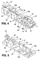
- Figs.2 to 5 show a practical embodiment of the fiber stretcher in which references are used corresponding to those used in the diagrammatic Figs. 1a and 1b.
- the base 10 is a solid body of metal which is machined to provide a platform part 30 with an upstanding pedestal portion 32 integrally connected to the lever part 14 by the flexure 12 forming a fulcrum.
- the flexure is provided by a thin web of metal defined by the adjacent sides of two closely situated cylindrical bores 34 drilled perpendicularly to the flat underside the base platform 30. So that the lever part 14 is separated from the base, apart from its web connection, two slits 35, 36 are formed leading from the two outer sides of the two bores 34 to the opposite ends of the pedestal portion 32, and the underside of the lever part, including the lever arm 14a, is separated from the platform part of the base by a horizontal cut 38.
- the flexure 12 between the base part and the lever part allows substantially frictionless movement of the lever arm through a small angle, typically about 1°, with only a small amount of force being required to move the lever.
- an upstanding lug 40 Integrally formed with an end of the base remote from pedestal 32 is an upstanding lug 40 which, by means of screw 41, carries the first, fixed fiber holder 16.
- This holder has an arm 16a extending towards the pedestal 32, the arm terminating in a platform 16b to which a portion of the fiber F is bonded.
- a bracket 42 extending up from the pedestal end of the lever part 14 carries the outer end of the second, movable fiber holder 18 which has an arm 18a extending towards the first fiber holder and has, on its inner end, a platform 18b to which another portion of the fiber is bonded.
- the lever part 14 has a rearwards extension behind (i.e. on the other side from lever arm 14a) the fulcrum where it has a recess holding an inner end of an electromagnetic coil 22 which is movable within a steel yoke 23.
- the outer end of the lever arm 14a extends between two blocks 44, 45, fitted into recesses 30a in the base platform 30 on opposite sides of the arm. These blocks hold, firstly, an opposed pair of adjustable stops 24, which are adjustable by screws 24a at the outer sides of the blocks 44, 45, and secondly the blocks hold an opposed pair of permanent magnets 26 which interact with a permanent magnet 27 mounted on the lever arm. This arrangement ensures that the lever arm is biassed into one of the two positions where it is in contact with one of the two adjustable stops 24; the magnets 26 remain out of contact with the central magnet 27.
- the amount of stretching provided by this device can be accurately controlled, due to several factors, i.e.:
- the effective lever length L2 between the movable holding means 18b and the fulcrum is typically less than 1/10 the length of lever arm L1 between the fulcrum and the stops 24, so that the motion of the fiber holding means is less than 1/10 that of the outer end portion of the lever.
- electro-magnetic means may be used to move the lever, for example a magnet movable in a coil, or a coil movable in a coil.
- Such means, and latching means may be capable of providing more than two stable positions and thus more than a single degree of stretch for the fiber.
Landscapes
- Physics & Mathematics (AREA)
- General Physics & Mathematics (AREA)
- Optics & Photonics (AREA)
- Nonlinear Science (AREA)
- Mechanical Light Control Or Optical Switches (AREA)
- Diffracting Gratings Or Hologram Optical Elements (AREA)
- Light Guides In General And Applications Therefor (AREA)
Applications Claiming Priority (2)
| Application Number | Priority Date | Filing Date | Title |
|---|---|---|---|
| US523101 | 2000-03-10 | ||
| US09/523,101 US6396994B1 (en) | 2000-03-10 | 2000-03-10 | Apparatus for varying the optical characteristics of an optical fiber by stretching the fiber |
Publications (2)
| Publication Number | Publication Date |
|---|---|
| EP1136858A2 true EP1136858A2 (fr) | 2001-09-26 |
| EP1136858A3 EP1136858A3 (fr) | 2004-03-17 |
Family
ID=24083663
Family Applications (1)
| Application Number | Title | Priority Date | Filing Date |
|---|---|---|---|
| EP01302023A Withdrawn EP1136858A3 (fr) | 2000-03-10 | 2001-03-06 | Dispositif pour varier les caractéristiques optiques d'une fibre optique en l'étirant |
Country Status (4)
| Country | Link |
|---|---|
| US (1) | US6396994B1 (fr) |
| EP (1) | EP1136858A3 (fr) |
| CN (1) | CN1319771A (fr) |
| CA (1) | CA2334837A1 (fr) |
Families Citing this family (12)
| Publication number | Priority date | Publication date | Assignee | Title |
|---|---|---|---|---|
| US6584269B1 (en) * | 2001-11-25 | 2003-06-24 | Ciena Corporation | Fiber optic cable tensioning and positioning apparatus |
| US6868212B2 (en) * | 2003-03-06 | 2005-03-15 | Evans & Sutherland Computer Corporation | Method and apparatus for controlling wavelength and dominant mode in fiber lasers |
| US7891818B2 (en) | 2006-12-12 | 2011-02-22 | Evans & Sutherland Computer Corporation | System and method for aligning RGB light in a single modulator projector |
| US7382962B1 (en) * | 2007-09-06 | 2008-06-03 | General Photonics Corporation | Fiber stretcher apparatus |
| US7945130B2 (en) * | 2007-11-15 | 2011-05-17 | General Photonics Corporation | Mode scrambling apparatus for multimode fiber |
| US8358317B2 (en) | 2008-05-23 | 2013-01-22 | Evans & Sutherland Computer Corporation | System and method for displaying a planar image on a curved surface |
| US8702248B1 (en) | 2008-06-11 | 2014-04-22 | Evans & Sutherland Computer Corporation | Projection method for reducing interpixel gaps on a viewing surface |
| US8077378B1 (en) | 2008-11-12 | 2011-12-13 | Evans & Sutherland Computer Corporation | Calibration system and method for light modulation device |
| US8780433B2 (en) | 2011-09-28 | 2014-07-15 | General Photonics Corporation | Polarization scrambling based on cascaded optical polarization devices having modulated optical retardation |
| US9641826B1 (en) | 2011-10-06 | 2017-05-02 | Evans & Sutherland Computer Corporation | System and method for displaying distant 3-D stereo on a dome surface |
| US9891121B2 (en) * | 2012-05-24 | 2018-02-13 | Halliburton Energy Services, Inc. | Attachment method to keep optical fiber in tension |
| CN109000809B (zh) * | 2018-07-17 | 2019-10-22 | 南通大学 | 一种马赫-曾德尔干涉仪及其制作设备和制作方法 |
Family Cites Families (5)
| Publication number | Priority date | Publication date | Assignee | Title |
|---|---|---|---|---|
| FR2397272A1 (fr) * | 1977-07-13 | 1979-02-09 | Cit Alcatel | Outil a main pour couper une fibre optique |
| DE3023959C2 (de) * | 1980-06-26 | 1986-06-26 | Schubert & Salzer Maschinenfabrik Ag, 8070 Ingolstadt | Verfahren und Vorrichtung zum Anspinnen eines Fadens in einem Spinnrotor einer Offenend-Spinnvorrichtung |
| US5999671A (en) * | 1997-10-27 | 1999-12-07 | Lucent Technologies Inc. | Tunable long-period optical grating device and optical systems employing same |
| US6175108B1 (en) * | 1998-01-30 | 2001-01-16 | Cidra Corporation | Accelerometer featuring fiber optic bragg grating sensor for providing multiplexed multi-axis acceleration sensing |
| US6240220B1 (en) * | 1998-07-29 | 2001-05-29 | E-Tek Dynamics, Inc. | Tunable optical fiber package |
-
2000
- 2000-03-10 US US09/523,101 patent/US6396994B1/en not_active Expired - Fee Related
-
2001
- 2001-02-08 CA CA002334837A patent/CA2334837A1/fr not_active Abandoned
- 2001-03-06 EP EP01302023A patent/EP1136858A3/fr not_active Withdrawn
- 2001-03-09 CN CN01111311A patent/CN1319771A/zh active Pending
Also Published As
| Publication number | Publication date |
|---|---|
| EP1136858A3 (fr) | 2004-03-17 |
| CN1319771A (zh) | 2001-10-31 |
| US6396994B1 (en) | 2002-05-28 |
| CA2334837A1 (fr) | 2001-09-10 |
Similar Documents
| Publication | Publication Date | Title |
|---|---|---|
| US6396994B1 (en) | Apparatus for varying the optical characteristics of an optical fiber by stretching the fiber | |
| US5239599A (en) | Moving fiber optical fiber switch | |
| US5594820A (en) | Opto-mechanical device having optical element movable by twin flexures | |
| JP3597095B2 (ja) | 光スイッチングデバイスおよび光クロス接続スイッチングデバイス | |
| KR970050733A (ko) | 헤드액츄에이터 | |
| KR910008763A (ko) | 저레벨의 자기 트립을 조정할 수 있는 회로 차단기 | |
| US6085016A (en) | Magnetically controlled variable optical attenuator | |
| EP0160011A1 (fr) | Commutateur a fibres optiques. | |
| US6606429B1 (en) | Electromechanically controlled optical element | |
| KR940024695A (ko) | 광학 디스크드라이브에 대한 전자기 렌즈 액추에이터 | |
| GB2030319A (en) | Optical fibre switching arrangements | |
| US5719972A (en) | Optical switch | |
| JP3859120B2 (ja) | 光スイッチ | |
| KR20050010920A (ko) | 광 스위치 | |
| DK732588D0 (da) | Elektromagnetisk styret kontakt | |
| US6990267B2 (en) | Moving fiber optical switch | |
| JP2002323663A (ja) | クロスコネクト光スイッチ | |
| WO2004068192A3 (fr) | Commutateur optique pour fibre optique | |
| JP2001235690A (ja) | 光スイッチ | |
| US5661827A (en) | Optical switch having a reflector | |
| KR100722055B1 (ko) | 광 스위치 및 광 스위치 유닛 | |
| SU1606953A1 (ru) | Волоконно-оптический переключатель | |
| US20090051228A1 (en) | Actuator unit | |
| JPH05157981A (ja) | 光ファイバー駆動リレー | |
| JP3709677B2 (ja) | 光スイッチ |
Legal Events
| Date | Code | Title | Description |
|---|---|---|---|
| PUAI | Public reference made under article 153(3) epc to a published international application that has entered the european phase |
Free format text: ORIGINAL CODE: 0009012 |
|
| AK | Designated contracting states |
Kind code of ref document: A2 Designated state(s): AT BE CH CY DE DK ES FI FR GB GR IE IT LI LU MC NL PT SE TR |
|
| AX | Request for extension of the european patent |
Free format text: AL;LT;LV;MK;RO;SI |
|
| PUAL | Search report despatched |
Free format text: ORIGINAL CODE: 0009013 |
|
| STAA | Information on the status of an ep patent application or granted ep patent |
Free format text: STATUS: THE APPLICATION IS DEEMED TO BE WITHDRAWN |
|
| AK | Designated contracting states |
Kind code of ref document: A3 Designated state(s): AT BE CH CY DE DK ES FI FR GB GR IE IT LI LU MC NL PT SE TR |
|
| AX | Request for extension of the european patent |
Extension state: AL LT LV MK RO SI |
|
| 18D | Application deemed to be withdrawn |
Effective date: 20031001 |