EP1136793A2 - A map display device, a memory medium and a map display method - Google Patents
A map display device, a memory medium and a map display method Download PDFInfo
- Publication number
- EP1136793A2 EP1136793A2 EP01106922A EP01106922A EP1136793A2 EP 1136793 A2 EP1136793 A2 EP 1136793A2 EP 01106922 A EP01106922 A EP 01106922A EP 01106922 A EP01106922 A EP 01106922A EP 1136793 A2 EP1136793 A2 EP 1136793A2
- Authority
- EP
- European Patent Office
- Prior art keywords
- polygon
- map
- data
- display
- polygon map
- Prior art date
- Legal status (The legal status is an assumption and is not a legal conclusion. Google has not performed a legal analysis and makes no representation as to the accuracy of the status listed.)
- Withdrawn
Links
- 238000000034 method Methods 0.000 title description 4
- 238000012545 processing Methods 0.000 claims abstract description 63
- 230000006870 function Effects 0.000 claims abstract description 8
- 238000004891 communication Methods 0.000 description 9
- 238000010586 diagram Methods 0.000 description 7
- 239000000203 mixture Substances 0.000 description 5
- 238000012546 transfer Methods 0.000 description 5
- 238000004364 calculation method Methods 0.000 description 4
- 239000003086 colorant Substances 0.000 description 4
- 238000013461 design Methods 0.000 description 4
- 230000001413 cellular effect Effects 0.000 description 2
- 238000013500 data storage Methods 0.000 description 2
- 230000000977 initiatory effect Effects 0.000 description 2
- 238000003745 diagnosis Methods 0.000 description 1
- 230000003993 interaction Effects 0.000 description 1
- 230000002452 interceptive effect Effects 0.000 description 1
- 239000004973 liquid crystal related substance Substances 0.000 description 1
- 238000004519 manufacturing process Methods 0.000 description 1
- 230000004044 response Effects 0.000 description 1
- 239000013589 supplement Substances 0.000 description 1
- 230000002194 synthesizing effect Effects 0.000 description 1
- 230000001131 transforming effect Effects 0.000 description 1
Images


Classifications
-
- G—PHYSICS
- G01—MEASURING; TESTING
- G01C—MEASURING DISTANCES, LEVELS OR BEARINGS; SURVEYING; NAVIGATION; GYROSCOPIC INSTRUMENTS; PHOTOGRAMMETRY OR VIDEOGRAMMETRY
- G01C21/00—Navigation; Navigational instruments not provided for in groups G01C1/00 - G01C19/00
- G01C21/38—Electronic maps specially adapted for navigation; Updating thereof
- G01C21/3863—Structures of map data
- G01C21/3867—Geometry of map features, e.g. shape points, polygons or for simplified maps
-
- G—PHYSICS
- G01—MEASURING; TESTING
- G01C—MEASURING DISTANCES, LEVELS OR BEARINGS; SURVEYING; NAVIGATION; GYROSCOPIC INSTRUMENTS; PHOTOGRAMMETRY OR VIDEOGRAMMETRY
- G01C21/00—Navigation; Navigational instruments not provided for in groups G01C1/00 - G01C19/00
- G01C21/26—Navigation; Navigational instruments not provided for in groups G01C1/00 - G01C19/00 specially adapted for navigation in a road network
- G01C21/34—Route searching; Route guidance
- G01C21/36—Input/output arrangements for on-board computers
- G01C21/3667—Display of a road map
-
- G—PHYSICS
- G09—EDUCATION; CRYPTOGRAPHY; DISPLAY; ADVERTISING; SEALS
- G09B—EDUCATIONAL OR DEMONSTRATION APPLIANCES; APPLIANCES FOR TEACHING, OR COMMUNICATING WITH, THE BLIND, DEAF OR MUTE; MODELS; PLANETARIA; GLOBES; MAPS; DIAGRAMS
- G09B29/00—Maps; Plans; Charts; Diagrams, e.g. route diagram
- G09B29/10—Map spot or coordinate position indicators; Map reading aids
- G09B29/106—Map spot or coordinate position indicators; Map reading aids using electronic means
Definitions
- the present invention relates to a map display system for drawing a polygon map by determining a unit of a polygon map to be displayed in the background of a road map, and a memory medium.
- a map display of a navigation system polygon maps showing boundaries of administrative divisions have been displayed in the background of a road map. Since data of these polygon maps has one certain administrative division unit and a color stored, when a map is displayed on any scales, polygon maps are displayed in the same unit and color. Therefore, for example, a large area map has boundaries of the administrative divisions of Japan: the prefectures plus Tokyo, Hokkaido, Osaka, and Kyoto displayed thereon, on the other hand, a detailed map is displayed without showing the boundaries of the administrative divisions, and the background color of the road map is displayed in the same one unified color on all the scales.
- the present invention is provided to solve the above problems, therefore, has its principal object to display a map that is easy to be understood so as to prevent boundaries of administrative divisions from being mistaken for roads on any scales.
- a map display system comprises input means for inputting a display scale, memory means for storing polygon map data, drawing processing control means for drawing a polygon map by reading the polygon map data from said memory means and display means for displaying an output from said drawing processing control means, wherein said drawing processing control means draws a display condition of each polygon differently from others.
- a memory medium stores therein a polygon map database in which information showing display conditions of polygons are set up and a program for drawing a display condition of each polygon differently from others and output.
- Fig.1 shows an example of composition of a navigation system according to the present invention.
- Fig. 2 is a flowchart describing the entire system.
- Figs. 3 (A), (B) and (C) show an example of road map data file structure.
- Figs. 4 (a), (b) and (c) show a set of diagrams describing a data structure of a polygon map.
- Fig. 5 is a flowchart describing address polygon drawing processing.
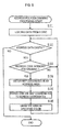
- Fig. 6 is a flowchart describing specified address polygon drawing processing.
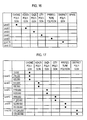
- Fig. 7 is a diagram describing a polygon map data storage table.
- Fig. 8 is a diagram describing a polygon map data use table.
- Fig. 9 shows road maps of which backgrounds are drawn with Oaza polygon maps of 1/5,000, 1/10,000 and 1/20,000.
- Fig. 10 shows road maps of which backgrounds are drawn with Oaza polygon map of 1/40,000 and City/Ward/Town/Village polygon of 1/80,000.
- Fig. 11 shows road maps of which background are drawn with City/Ward/Town/Village polygon maps of 1/160,000 and 1/320,000.
- Fig. 12 shows road maps of which background are drawn with City/Ward/Town/Village polygon map of 1/640,000 and Prefecture polygon map of 1/1,280,000.
- Fig. 13 is a flowchart showing polygon map composing processing.
- Fig. 14 is a diagram showing a prefecture polygon produced from City/Ward/Town/Village polygons.
- Figs 15 (a), (b) and (c) are diagrams showing a prefecture polygon and a district polygon respectively composed of city/ward/town/village polygons.
- Fig 16 shows another example of a polygon map data storage table.
- Fig 17 shows another example of a polygon map data use table.
- Fig. 18 a flowchart describing an example of processing for drawing a map by using data of a polygon map including a cursor position when a cursor move instruction is input.
- Fig. 19 is a flowchart describing an example of drawing processing for preventing the entire range of display from being included in one polygon map.
- Fig.1 is a diagram showing an example of composition of a navigation system to which a map display device according to the present invention is applied. It is composed of an input device 1 for inputting information on route guidance, a present position detecting device 2 for detecting information on a vehicle present position, information memory device 3 for storing therein navigation data as required for calculation of routes, display/audio guidance data as necessary for route guidance, programs (application and/or OS) and the like, a central processing unit 4 for performing route search processing, data production as required for route guidance, display/voice guidance processing as required for route guidance and further the entire system control, an information transmitter/receiver 5 for transmitting and receiving road information on the vehicle, for example, road information or traffic information and for detecting information on the vehicle present position and further transmitting and receiving information on the vehicle present position and an output device 6 for outputting information on route guidance.
- an input device 1 for inputting information on route guidance
- a present position detecting device 2 for detecting information on a vehicle present position
- information memory device 3 for storing therein navigation
- the input device 1 is provided with functions for inputting a destination and instructing the central processing unit 4 to execute the navigation processing in conformity with a driver's intention.
- a remote controller and the like such as a touch switch or a jog dial and the like for inputting a destination in the form of a telephone number or a point of coordinates on a map etc., and for requesting route guidance can be used.
- the invention is provided with a device for performing an interaction by voice input, which functions as a voice input device.
- a record card reader for reading data recorded in an IC card or a magnetic card.
- a data communication device which is for data communications between information sources such as an information center for accumulating therein data necessary for navigation and providing information via communication links upon the driver's request, and a portable style electronic device etc. stored therein map data, destination data, data of a simple frame map, a building shaped map or the like.
- the present position detecting device 2 includes a GPS receiver for calculating the vehicle present position, a traveling speed or an absolute direction by using a global positioning system (GPS), a beacon receiver for receiving information such as vehicle present position information, lane information and the like, a data receiver for receiving a corrective signal of the GPS by using a cellular telephone (a car telephone) or a FM multiplex signal, an absolute direction sensor for detecting the travel direction of the vehicle with an absolute direction by using, for example, a geomagnetic, a relative direction sensor for detecting the travel direction of the vehicle by using, for example, a steering sensor and a gyro sensor, a distance sensor for detecting the travel distance, for example, from a number of revolutions of a wheel and the like.
- GPS global positioning system
- a beacon receiver for receiving information such as vehicle present position information, lane information and the like
- a data receiver for receiving a corrective signal of the GPS by using a cellular telephone (a car telephone) or a FM multiplex signal
- the information memory device 3 is a storage device in which programs and data for navigation are stored, for example, composed of an external memory medium, such as a CD-ROM, a DVD-ROM, a floppy disc, a memory card etc. It may be composed of an internal storage device, such as a ROM, a flash memory in the system unit etc.
- the stored programs therein include a program for performing processing, such as a route search etc., a program for performing guidance in an interactive manner by a voice input, a program for performing display/ voice output control necessary for route guidance, a program for searching a point or a facility and the like.
- the data stored therein are composed of files, such as road map data, polygon map data, search data, map matching data, destination data, register point data, image data of junction points, such as an intersection etc., genre data and the like, in which all the data necessary for navigation are stored.
- the invention can be applied to a kind of system in which the CD-ROM only stores the data and the central processing unit stores the programs, or the data and the programs are obtained from outside by communications.
- the central processing unit 4 includes a CPU for performing various calculation processing, a flash memory for reading and storing the programs from the CD-ROM of the information memory device 3, a ROM in which a program (or program reading means) for checking and updating the programs contained in the flash memory; a RAM for temporarily storing the searched route guidance information, such as a point of coordinates of the determined destination, a road name code number and the like, or data under the calculation processing.
- said central processing unit further provides a voice processor for performing communication processing by a voice input from the input device 1, for synthesizing a voice, a phase, one sentence, a sound and the like read from the information memory device 3 on the basis of the voice output control signals from the CPU and transforming them into analog signals and outputting to a speaker, a communication interface for transferring the input/output data, a sensor input interface for receiving a sensor signal of the present position detecting device 2, for determining a present position and for determining a cursor position on a screen, and a clock for writing the date and time in internal diagnosis information.
- programs for performing said updating processing may be stored in an external memory device.
- the programs according to the present invention and the other programs for executing navigation may be wholly stored in a CD-ROM as an external memory medium, or they may be partially or wholly stored in the ROM 42.
- the data and programs as stored in the external memory medium are input as external signals to the central processing unit of the navigation system and processed by calculation so that various navigation functions are realized.
- the navigation system embeds therein the flash memory having a relatively large capacity for reading programs from the CD-ROM of the external memory device and the ROM having a small capacity that stores a program (or program reading means) for performing an initiation processing of the CD.
- the flash memory is maintained therein the stored information even if the power is turned off, namely nonvolatile memory means.
- the program stored in the ROM or in another word the program reading means are initiated to check the programs stored in the flash memory and load the disc managing information etc. stored in the CD-ROM of the information memory device 3.
- the loading processing (or updating processing) of the programs is performed by the judgment on this information and the state of the flash memory.
- the information transmitter/receiver 5 comprises a GPS receiver for obtaining information by making use of the satellite navigation system (GPS), a VICS information receiver for obtaining information by making use of FM multi-channels, electric beacons, light beacons etc., a data transmitter/receiver is exemplified by a cellular telephone, a personal computer, etc. for exchanging the information with an information centre (e.g., ATIS) or other vehicles, and the like.
- GPS satellite navigation system
- VICS information receiver for obtaining information by making use of FM multi-channels, electric beacons, light beacons etc.
- a data transmitter/receiver is exemplified by a cellular telephone, a personal computer, etc. for exchanging the information with an information centre (e.g., ATIS) or other vehicles, and the like.
- ATIS information centre
- the output device 6 is provided with functions for outputting guidance information in the form of voice or display when required by the driver and for outputting the navigation data processed in the CPU 4 to the printer.
- the output device 6 comprises a display for displaying input data on a screen or for displaying a route guidance screen, a printer for printing out data processed in the CPU 4 or data stored in the information memory device 3, a speaker for outputting route guidance in the form of voice, and the like.
- the display includes a color CRT or liquid-crystal display device etc., and displays screens showing a polygon map screen processed in the CPU 4, a road map screen, an intersection enlarged screen, arrows for showing destination names, time, distances, travel directions, and the like. Since image data to be transmitted to the display is bitmap data, they can also be transmitted through a communication line used for a serial communication etc., or through the sharing of other communication lines, not through the exclusive image signal line. Further, the display may be equipped with a memory for temporarily storing the bitmap data.
- That display is mounted inside of the instrument panel in the vicinity of the driver's seat. Observing the interval screen enables the driver to ascertain the present position of the vehicle and to obtain information on a next route to follow.
- the display may be composed that points or roads etc. can be input by touching or tracing the screen with making use of a tablet including a touch panel, a touch screen etc. on the display screen, however, a figure thereof is omitted.
- Fig. 2 is a flowchart describing the entire system.
- a present position is detected by the present position detecting device 2 and a name of the present position as well as a vicinity map with the present position being located at its center are displayed (step S1).
- a destination is set by use of a destination name such as a place name, a facility name or the like, a telephone number, an address, a register point, a road name or the like (step S2), a route from the present position to the destination is searched (step S3).
- route guidance/display are repeatedly performed until the vehicle reaches the destination while tracing the present position by the present position detecting device 2 (step S4).
- a searching area based on the stop is newly set and a route search is performed again within the set searching area, and the route guidance is repeatedly performed until the vehicle reaches the destination in the same way as previously mentioned.
- Figs. 3 (A), (B) and (C) show an example of road map data file structure stored in the information memory device 3 according to the present invention shown in Fig. 1.
- Fig. 3 (A) shows a part of the road map data file, in which each of the number of roads (n) has each data of road number data, length data, road coordinate data, shape data address/size and guidance data address/size.
- Said road number data has road numbers independently set for each direction (approaching path and return path) of a road between branch points.
- Said road coordinate data as road guidance supplement information data is composed of data indicative of the road whether it is an elevated road, a road next to the elevated road, a subway or a road next to the subway, information on the number of lanes in the road, branch point data (a flag showing whether or not the road has branch point) and ramp data (a flag showing whether the road is a ramp or not).
- Said shape data has coordinate data composed of east longitude and north latitude with respect to each of the number of nodes (m) when each road is divided by a plurality of nodes (sections), as shown in Fig. 3 (B).
- Said guidance data is composed of each data of intersection (or branch point) name data, caution data, road name data, road name voice data address/size and destination data address/size, as shown in Fig. 3 (C). Further, apart from these data, textual data or landmark data to be displayed on a screen may include as road map data.
- Figs. 4 (a), (b) and (c) show diagrams describing a data structure of a polygon map stored in the information memory device 3 according to the present invention as shown in Fig. 1.
- the polygon map data is map data showing a boundary of an area (usually, administrative division) such as the whole of Japan, the eastern district of Japan, the western district of Japan, the Tohoku district of Japan, the Kansai district of Japan, the prefecture, the city/ward/town/village or the like, which includes as shown in Fig.
- a classification showing unit information on an administrative division such as a prefecture (including Tokyo, Hokkaido, Osaka or Kyoto), or a city/a ward/a town/a village (a municipality) and display level information, a color code for displaying an administrative division on a map, an address code, attribute data such as the number of points of coordinates showing a closed area, and coordinate sequence data for showing a boundary of the closed area, are stored in the information memory device with road map data. Further, the polygon data is classified on the basis of each display level and stored. In this embodiment, polygons are distinguished and displayed by 5 colors, information memory means stores therein a color table showing color codes which was made corresponded to these 5 colors and a color is displayed by referring to this table.
- an administrative division such as a prefecture (including Tokyo, Hokkaido, Osaka or Kyoto), or a city/a ward/a town/a village (a municipality) and display level information
- a color code for displaying an administrative division on a map an address code
- brightness information, design information or the like may be stored besides or instead of the color information.
- a brightness table or a design table is stored and a polygon to be displayed is shown its brightness or design being different from another on the basis of each area.
- a structure of the coordinate data is constructed as data of vector sequence connecting between a starting point and an end point, and a boundary of the closed area is formed by connecting each vector, as shown in Fig. 4(b).
- the address code shows an address to which the polygon is belonging, for example, it includes a district (Tokai district, Hokuriku district, Kinki district, Kanto district etc.), a prefecture, a city, a ward, a town, a village, Oaza (a large section of village), Koaza (a small section of village), Chome, Banchi (a lot number) and Go (a number) as shown in Fig. 4 (c).
- a map to be drawn by this polygon data shows only a boundary of the area and the amount of used data is small, therefore, data processing for drawing a map is easily executed.
- административн ⁇ е ⁇ ии are distinguished and displayed by colors in any scales in order that boundaries of those administrative areas are easy to understand and the vehicle present position is read out promptly when this polygon map is drawn as a background image in this present invention.
- a unit of a polygon map to be displayed and a color of each polygon map area automatically changed as giving an instruction for changing a scale.
- a new polygon map including the present position is displayed in the same unit as the previous polygon map and a color of a polygon map including the present position is displayed in a color different from adjacent polygon maps one after another.
- the present position is a vehicle present potion detected by the present position detecting device or a scroll datum position of a map scroll input by the input device such as a remote controller or the like.
- Figs. 5 and 6 are flowcharts describing a flow of processing for drawing a map (the background of road map) showing an address area by using polygon map data shown in Figs. 4 (a), (b) and (c).
- Fig. 5 is a flow of address polygon drawing processing. This processing is executed when a map is displayed on a screen of the navigation system or every time the scale change is instructed by operating a detail button and a large area button for changing the scale of the displayed map, in which drawing processing is automatically executed by reading data of all the polygon maps in the predetermined range of area including the range of display.
- step S11 polygon map data in the predetermined range of area including the range of display are loaded from a disc (step S11), it is judged whether or not there is address data should be drawn (step S12), if there is the address data, map coordinates (a sequence of coordinates) corresponding thereto (step S13), the map coordinates are transformed to screen coordinates (step S14), an area is drawn in a specified drawing color by referring to the color table corresponding to color codes (step S15), and the same processing is carried out as returning to step 12 . Then, when there is no address data should be drawn at step 12, the processing is completed.
- Fig. 6 is a flowchart describing drawing processing of a specified address polygon. This processing is executed when a cursor specifying a position on a screen is stopped, the position is input as a point and a map around that point is displayed, or it is executed each time a present position mark blinks (a cycle of matching between the moving track and the map), it is namely, the drawing processing executed every time the present position is moved.
- step S21 data of a predetermined range including a range of display is loaded from a disc (step S21), it is judged whether or not there is address data should be drawn (step S22), if there is the address data, it is then judged whether or not the address data is an address code intended for drawing (step S23), and if it is not the address code intended for drawing, the processing returns to step S22 again. If it is the address code intended for drawing, map coordinates (coordinate sequence) of an address area corresponding to it is obtained (step S24), map coordinates are transformed to screen coordinates (step S25), the area is drawn in a drawing color specified as attribute data (step S26) and the same processing is executed again in the same manner by returning to step S22. Then, it is completed when no address data should be drawn at step S22.
- Figs. 7 and 8 show examples of address polygon database used in the present invention. These data are stored in the information memory device with the polygon map data shown in Fig. 4.
- Fig. 7 shows an example of polygon map data storing table, in which levels 0 to 12 are corresponding to the amount of map information to be displayed (the number of points of polygon coordinates), its number becomes smaller as the level is higher. This is to prevent the fact because handling data of a large range causes an increase of the amount of data in a large area map where the level is high, and in consequence taking time for drawing slows down its speed.
- the information memory device stores therein data of Levels 0 and2 for Oaza polygon, Levels 2, 4, and 6 for City/Ward/Town/Village polygon and Levels 6, 8, and 10 for Prefecture polygon. Namely, a plurality of polygon map data having the different amount of data for each polygon unit is stored.
- Levels 2 and 6 are respectively corresponding to two polygon units and the same amount of data are stored even if the polygon units are different, therefore, a unit which is clearly viewed is selected according to the display scale. Further, there is no polygon provided in Level 12, however, this is a spare prepared for a bigger unit such as a district polygon, a polygon of the whole of Japan, a polygon for overseas use or the like.
- the polygon map data may be stored on the basis of each scale instead of each level described as above.
- Fig. 8 shows a polygon map data use table, in which the rate of scale and a polygon unit corresponding thereto are provided to each level.
- Oaza polygons of 1/5,000, 1/10,000 and 1/20,000 in Level 0 Oaza polygon of 1/40,000 and City/Ward/Town/Village polygon of 1/80.000 in Level 2
- City/Ward/Town/Village polygons of 1/160,000 and 1/320,000 in Level 4 City/Ward/Town/Village polygon of 1/640,000 and Prefecture polygon of 1/1,280,000 in Level 6
- Each data in the same level has the same amount of data stored even if the sales thereof are different, however, the amount of data displayed is bigger in a large area map so that it requires more time to draw a large area. Therefore, the amount of data is encouraged to reduce as the level becomes higher so as to prevent the speed of drawing from slowing down.
- the polygon unit and the drawing level are determined by referring to the polygon map data using table, the determined polygon map data is read out, and a map can be drawn.
- Fig. 9 shows road maps of which backgrounds are drawn with Oaza polygon maps of 1/5,000, 1/10,000 and 1/20,000 in Level 0
- Fig. 10 shows road maps of which backgrounds are drawn with Oaza polygon map of 1/40,000 and City/Ward/Town/Village polygon of 1/80,000 in Level 2
- Fig. 11 shows road maps of which background are drawn with City/Ward/Town/Village polygon maps of 1/160,000 and 1/320,000 in Level 4, and Fig.
- FIG. 12 shows road maps of which backgrounds are drawn with City/Ward/Town/Village polygon map of 1/640,000 and Prefecture polygon map of 1/1,280,000 in Level 6, wherein polygon maps are respectively distinguished in colors in respective levels. Further, if the Oaza polygon of 1/40,000 is too small in Level 2, a map is drawn with the City/Ward/Town/Village polygon of 1/80,000, on the other hand, if the City/Ward/Town/Village polygon of 1/80,000 is too rough, a map can be drawn with the Oaza polygon of 1/40,000.
- Figs 13 to 15 describe the second embodiment in which only one type of polygon map data is stored.
- the polygon map data has only one smallest unit polygon data stored and other polygon map data units bigger than it is made up by composing from the smallest unit polygon data.
- a polygon map unit Prefecture, City/Ward/Town/Village, Oaza etc.
- a polygon map unit corresponding to the input scale is determined from the polygon map data use table (Fig. 8) showing a correspondence between a scale and a polygon data map, and polygon map data is composed.
- Fig. 13 is a flowchart showing polygon map data composing processing of the present embodiment.
- Oaza polygon is stored as the smallest unit of the polygon map data, it is judged whether or not the scale rate instructed at a scale change by the user is 1/5,120,000 and under (step S31), if it is a large area map of 1/5,120,000 and under, area polygon map data is made up by composing from Oaza polygon (step S32), and if it is more than 1/5,120,000, it is judged whether or not the scale rate is 1/640,000 and under (step S33), if it is 1/640,000 and under, Prefecture polygon map data is made up by composing from the Oaza polygon (step S34), and if the scale rate is more than 1/640,000, City/Ward/Town/Village polygon map data is made up by composing from the Oaza polygon.
- polygon map data has information on address each of which comprising Prefecture, City/Town/Village, Oaza, Koaza, Chome, Banchi, and Gou, all the polygon map data storing therein an address code determined in response to the input scale (ex. Prefecture unit) are read out, and coordinate sequences thereof are respectively compared. For example, as shown in Fig.
- a prefecture polygon map is further composed from polygon maps of A city, B city and C city which are composed from Oaza polygons
- a polygon map data for example, in the polygon map of A city, two successive points of coordinates (P1, P2) composing a part of the polygon map data match with polygon map data of B city, a line connecting these successive points of coordinates is in common so that this coordinate data is omitted.
- This processing is executed on each polygon map, as the remained points of coordinates are connected, boundaries coming in contact each other are removed and polygon map data based on the prefecture unit is composed.
- Figs 15 (a), (b) and (c) show polygon maps composed as such, in which, Fig.
- Fig. 15 (a) is a map composed of city/ward/town/village polygons
- Fig. 15 (b) is a map composed of prefectural polygons
- Fig. 15 (c) is a map composed of district polygons.
- color information to be made up in this embodiment for example, an optional method that a color code is assigned in order of the compositions, in order of the size of polygons or the like, which may be applied.
- polygon map data on one unit has a plurality of levels stored in the information memory means (for example, polygon map data of Oaza has two data of levels 0 and 2), however, if such a composition is applied, the amount of data is increased and a large storage capacity is required. Therefore, the third embodiment for minimizing the storage capacity is described.
- the information memory means has one polygon map data (one level only) stored therein on the basis of one classification of districts (the Tokai district, the Tohoku district, the Kinki district, Kanto district etc.), prefectures (Aichi, Gifu, Mie etc.), cities/wards/towns/villages (Nagoya, Toyota, Kariya, Anjo etc.), Oaza, Koaza, Chome, Banchi, Gou or the like.
- districts the Tokai district, the Tohoku district, the Kinki district, Kanto district etc.
- prefectures Al, Gifu, Mie etc.
- cities/wards/towns/villages Nagoya, Toyota, Kariya, Anjo etc.
- Oaza Koaza
- Chome Banchi
- Gou or the like a corresponding table between levels showing the number of points of polygon coordinates and polygon units as shown in Fig. 16 and a corresponding table between scales and polygon units as shown in Fig. 17 are also stored. Since only one level is
- polygon map data corresponding to the scale is determined by referring to the polygon data corresponding table. For example, when the scale is 1/10,000, a map is drawn by using data of Chome-polygon and when it is 1/160,000, a map is drawn by using data of Oaza polygon. Since polygon data has color information, brightness information, design information and the like stored therein so as to be distinguished from other adjoining polygon data, there is no concern that adjoining polygons are drawn as if they are mixed each other.
- polygon map drawing processing is described on the basis of embodiments, however, the invention is not limited to the above embodiments and various forms can be realized.
- processing for drawing a polygon map by using all the polygon map data included in the range of drawing is described.
- a polygon map may be displayed by determining a present position (a vehicle present position or a cursor present position) and using only the polygon map data in which said determined present position is included (polygon data in which the preset position is included is only loaded at step S11 shown in Fig. 5).
- drawing processing of a polygon map using only data of polygon including the cursor position may be executed instead of drawing processing using data of polygon maps within the predetermined range including the range of display. This example is described with reference to Fig.
- step S41 it is judged whether or not the cursor move instruction is input (step S41), if it is judged that the cursor transfer instruction is input, only polygon map data including the cursor position is loaded (step S42), if it is judged that the cursor transfer instruction is not input, all the polygon map data within the predetermined range including the range of display is loaded (step S43), after that, if is judged whether or not there is address data should be drawn (step S44), if there is map data, map coordinates (coordinate sequence) of the address area corresponding thereto are/is obtained (step S45), the map coordinates are transformed to screen coordinates (step S46), the area is drawn in a drawing color specified from color codes by referring to a color table (step S47) and returning to step S44 and the same processing is executed. Then, when there is no more address data should be drawn at step S44, the processing is completed.
- a polygon unit is determined from the display scale input by applying polygon use tables (Figs. 8 and 17) in which the display scales and polygon units are corresponding each other.
- Figs. 8 and 17 the entire range of display is likely to be included in one polygon, in that case, the entire display screen becomes eventually a unified display form. Therefore, an embodiment to avoid this problem will be described with reference to Fig. 19.
- step S51 only polygon map data including the datum point (a vehicle present position, a cursor present position, or a central position of the display screen) is loaded (step S51), then it is judged whether or not the entire coordinate sequence of the loaded polygon data is included in the range of display (step S52), if it is not included, the entire screen becomes a unified display form so that one unit smaller polygon map data is loaded (step S53), and it is judged in the same manner whether or not the entire coordinate sequence of that polygon map data is included in the range of display. This processing is repeated until the entire coordinate sequence of the loaded polygon map data is included in the display range.
- step S54 it is judged whether or not there is address data should be drawn (step S54), if there is address data, map coordinates (coordinate sequence) in an address area corresponding thereto is obtained (step S55), the map coordinates are transformed to screen coordinates (step S56), the area is drawn in a drawing color specified from a color code by referring to the color table (step S57) and returning to step S54 and the same processing is repeated. And, when there is no more address data should be drawn at step S54, the processing is completed.
- a unit of polygon map to be displayed is determined, for example, on the basis of the display scale or by making one polygon unit included, so as to a polygon map, therefore, a point such as a vehicle position is easily recognized.
Landscapes
- Engineering & Computer Science (AREA)
- Remote Sensing (AREA)
- Radar, Positioning & Navigation (AREA)
- Physics & Mathematics (AREA)
- General Physics & Mathematics (AREA)
- Automation & Control Theory (AREA)
- Theoretical Computer Science (AREA)
- Business, Economics & Management (AREA)
- Educational Technology (AREA)
- Educational Administration (AREA)
- Mathematical Physics (AREA)
- Geometry (AREA)
- Navigation (AREA)
- Traffic Control Systems (AREA)
- Instructional Devices (AREA)
- Processing Or Creating Images (AREA)
Abstract
Description
- The present invention relates to a map display system for drawing a polygon map by determining a unit of a polygon map to be displayed in the background of a road map, and a memory medium.
- In the past, a map display of a navigation system, polygon maps showing boundaries of administrative divisions have been displayed in the background of a road map. Since data of these polygon maps has one certain administrative division unit and a color stored, when a map is displayed on any scales, polygon maps are displayed in the same unit and color. Therefore, for example, a large area map has boundaries of the administrative divisions of Japan: the prefectures plus Tokyo, Hokkaido, Osaka, and Kyoto displayed thereon, on the other hand, a detailed map is displayed without showing the boundaries of the administrative divisions, and the background color of the road map is displayed in the same one unified color on all the scales.
- There used to be problems that if polygon map data is stored on the basis of a small unit of administrative division (such as "0aza"-a large section of village), the unit of the polygon maps is too small and the entire map becomes difficult to be viewed when a large area map is displayed. On the other hand, if polygon map data is stored on the basis of a large unit (such as Prefecture), a screen is filled with one unified color and boundaries of the administrative divisions are not displayed when a detailed map is displayed so that information on a vehicle present position is difficult to be read from map information. There also used to be a problem that it is difficult to distinguish between boundaries and road information, because if the boundaries of administrative divisions are simply displayed with lines, the boundaries are likely mistaken for roads.
- The present invention is provided to solve the above problems, therefore, has its principal object to display a map that is easy to be understood so as to prevent boundaries of administrative divisions from being mistaken for roads on any scales.
- A map display system according to the present invention comprises input means for inputting a display scale, memory means for storing polygon map data, drawing processing control means for drawing a polygon map by reading the polygon map data from said memory means and display means for displaying an output from said drawing processing control means, wherein said drawing processing control means draws a display condition of each polygon differently from others.
- Further, a memory medium according to the present invention stores therein a polygon map database in which information showing display conditions of polygons are set up and a program for drawing a display condition of each polygon differently from others and output.
- Fig.1 shows an example of composition of a navigation system according to the present invention.
- Fig. 2 is a flowchart describing the entire system.
- Figs. 3 (A), (B) and (C) show an example of road map data file structure.
- Figs. 4 (a), (b) and (c) show a set of diagrams describing a data structure of a polygon map.
- Fig. 5 is a flowchart describing address polygon drawing processing.
- Fig. 6 is a flowchart describing specified address polygon drawing processing.
- Fig. 7 is a diagram describing a polygon map data storage table.
- Fig. 8 is a diagram describing a polygon map data use table.
- Fig. 9 shows road maps of which backgrounds are drawn with Oaza polygon maps of 1/5,000, 1/10,000 and 1/20,000.
- Fig. 10 shows road maps of which backgrounds are drawn with Oaza polygon map of 1/40,000 and City/Ward/Town/Village polygon of 1/80,000.
- Fig. 11 shows road maps of which background are drawn with City/Ward/Town/Village polygon maps of 1/160,000 and 1/320,000.
- Fig. 12 shows road maps of which background are drawn with City/Ward/Town/Village polygon map of 1/640,000 and Prefecture polygon map of 1/1,280,000.
- Fig. 13 is a flowchart showing polygon map composing processing.
- Fig. 14 is a diagram showing a prefecture polygon produced from City/Ward/Town/Village polygons.
- Figs 15 (a), (b) and (c) are diagrams showing a prefecture polygon and a district polygon respectively composed of city/ward/town/village polygons.
- Fig 16 shows another example of a polygon map data storage table.
- Fig 17 shows another example of a polygon map data use table.
- Fig. 18 a flowchart describing an example of processing for drawing a map by using data of a polygon map including a cursor position when a cursor move instruction is input.
- Fig. 19 is a flowchart describing an example of drawing processing for preventing the entire range of display from being included in one polygon map.
- The followings are embodiments of the invention, which will be described with reference to the drawings. Fig.1 is a diagram showing an example of composition of a navigation system to which a map display device according to the present invention is applied. It is composed of an
input device 1 for inputting information on route guidance, a presentposition detecting device 2 for detecting information on a vehicle present position,information memory device 3 for storing therein navigation data as required for calculation of routes, display/audio guidance data as necessary for route guidance, programs (application and/or OS) and the like, acentral processing unit 4 for performing route search processing, data production as required for route guidance, display/voice guidance processing as required for route guidance and further the entire system control, an information transmitter/receiver 5 for transmitting and receiving road information on the vehicle, for example, road information or traffic information and for detecting information on the vehicle present position and further transmitting and receiving information on the vehicle present position and anoutput device 6 for outputting information on route guidance. - The
input device 1 is provided with functions for inputting a destination and instructing thecentral processing unit 4 to execute the navigation processing in conformity with a driver's intention. As the means for attaining such functions, a remote controller and the like such as a touch switch or a jog dial and the like for inputting a destination in the form of a telephone number or a point of coordinates on a map etc., and for requesting route guidance can be used. Further, the invention is provided with a device for performing an interaction by voice input, which functions as a voice input device. There may also be added a record card reader for reading data recorded in an IC card or a magnetic card. Furthermore, there may be added a data communication device which is for data communications between information sources such as an information center for accumulating therein data necessary for navigation and providing information via communication links upon the driver's request, and a portable style electronic device etc. stored therein map data, destination data, data of a simple frame map, a building shaped map or the like. - The present
position detecting device 2 includes a GPS receiver for calculating the vehicle present position, a traveling speed or an absolute direction by using a global positioning system (GPS), a beacon receiver for receiving information such as vehicle present position information, lane information and the like, a data receiver for receiving a corrective signal of the GPS by using a cellular telephone (a car telephone) or a FM multiplex signal, an absolute direction sensor for detecting the travel direction of the vehicle with an absolute direction by using, for example, a geomagnetic, a relative direction sensor for detecting the travel direction of the vehicle by using, for example, a steering sensor and a gyro sensor, a distance sensor for detecting the travel distance, for example, from a number of revolutions of a wheel and the like. - The
information memory device 3 is a storage device in which programs and data for navigation are stored, for example, composed of an external memory medium, such as a CD-ROM, a DVD-ROM, a floppy disc, a memory card etc. It may be composed of an internal storage device, such as a ROM, a flash memory in the system unit etc. The stored programs therein include a program for performing processing, such as a route search etc., a program for performing guidance in an interactive manner by a voice input, a program for performing display/ voice output control necessary for route guidance, a program for searching a point or a facility and the like. The data stored therein are composed of files, such as road map data, polygon map data, search data, map matching data, destination data, register point data, image data of junction points, such as an intersection etc., genre data and the like, in which all the data necessary for navigation are stored. In addition, the invention can be applied to a kind of system in which the CD-ROM only stores the data and the central processing unit stores the programs, or the data and the programs are obtained from outside by communications. - The
central processing unit 4 includes a CPU for performing various calculation processing, a flash memory for reading and storing the programs from the CD-ROM of theinformation memory device 3, a ROM in which a program (or program reading means) for checking and updating the programs contained in the flash memory; a RAM for temporarily storing the searched route guidance information, such as a point of coordinates of the determined destination, a road name code number and the like, or data under the calculation processing. Although the figures are omitted, said central processing unit further provides a voice processor for performing communication processing by a voice input from theinput device 1, for synthesizing a voice, a phase, one sentence, a sound and the like read from theinformation memory device 3 on the basis of the voice output control signals from the CPU and transforming them into analog signals and outputting to a speaker, a communication interface for transferring the input/output data, a sensor input interface for receiving a sensor signal of the presentposition detecting device 2, for determining a present position and for determining a cursor position on a screen, and a clock for writing the date and time in internal diagnosis information. In addition, programs for performing said updating processing may be stored in an external memory device. - The programs according to the present invention and the other programs for executing navigation may be wholly stored in a CD-ROM as an external memory medium, or they may be partially or wholly stored in the ROM 42. The data and programs as stored in the external memory medium, are input as external signals to the central processing unit of the navigation system and processed by calculation so that various navigation functions are realized.
- As described above, the navigation system according to the present invention embeds therein the flash memory having a relatively large capacity for reading programs from the CD-ROM of the external memory device and the ROM having a small capacity that stores a program (or program reading means) for performing an initiation processing of the CD. The flash memory is maintained therein the stored information even if the power is turned off, namely nonvolatile memory means. And, as the initiation processing of the CD, the program stored in the ROM or in another word, the program reading means are initiated to check the programs stored in the flash memory and load the disc managing information etc. stored in the CD-ROM of the
information memory device 3. The loading processing (or updating processing) of the programs is performed by the judgment on this information and the state of the flash memory. - The information transmitter/receiver 5 comprises a GPS receiver for obtaining information by making use of the satellite navigation system (GPS), a VICS information receiver for obtaining information by making use of FM multi-channels, electric beacons, light beacons etc., a data transmitter/receiver is exemplified by a cellular telephone, a personal computer, etc. for exchanging the information with an information centre (e.g., ATIS) or other vehicles, and the like.
- The
output device 6 is provided with functions for outputting guidance information in the form of voice or display when required by the driver and for outputting the navigation data processed in theCPU 4 to the printer. As means for realizing these functions, theoutput device 6 comprises a display for displaying input data on a screen or for displaying a route guidance screen, a printer for printing out data processed in theCPU 4 or data stored in theinformation memory device 3, a speaker for outputting route guidance in the form of voice, and the like. - The display includes a color CRT or liquid-crystal display device etc., and displays screens showing a polygon map screen processed in the
CPU 4, a road map screen, an intersection enlarged screen, arrows for showing destination names, time, distances, travel directions, and the like. Since image data to be transmitted to the display is bitmap data, they can also be transmitted through a communication line used for a serial communication etc., or through the sharing of other communication lines, not through the exclusive image signal line. Further, the display may be equipped with a memory for temporarily storing the bitmap data. - That display is mounted inside of the instrument panel in the vicinity of the driver's seat. Observing the interval screen enables the driver to ascertain the present position of the vehicle and to obtain information on a next route to follow. Moreover, the display may be composed that points or roads etc. can be input by touching or tracing the screen with making use of a tablet including a touch panel, a touch screen etc. on the display screen, however, a figure thereof is omitted.
- Fig. 2 is a flowchart describing the entire system.
- As a program for route guidance is started upon the program is loaded from the
information memory device 3 to thecentral processing unit 4, a present position is detected by the presentposition detecting device 2 and a name of the present position as well as a vicinity map with the present position being located at its center are displayed (step S1). Next, a destination is set by use of a destination name such as a place name, a facility name or the like, a telephone number, an address, a register point, a road name or the like (step S2), a route from the present position to the destination is searched (step S3). As the route is determined, route guidance/display are repeatedly performed until the vehicle reaches the destination while tracing the present position by the present position detecting device 2 (step S4). If a stop on the way is set by input before reaching the destination, a searching area based on the stop is newly set and a route search is performed again within the set searching area, and the route guidance is repeatedly performed until the vehicle reaches the destination in the same way as previously mentioned. - Figs. 3 (A), (B) and (C) show an example of road map data file structure stored in the
information memory device 3 according to the present invention shown in Fig. 1. Fig. 3 (A) shows a part of the road map data file, in which each of the number of roads (n) has each data of road number data, length data, road coordinate data, shape data address/size and guidance data address/size. Said road number data has road numbers independently set for each direction (approaching path and return path) of a road between branch points. Said road coordinate data as road guidance supplement information data is composed of data indicative of the road whether it is an elevated road, a road next to the elevated road, a subway or a road next to the subway, information on the number of lanes in the road, branch point data (a flag showing whether or not the road has branch point) and ramp data (a flag showing whether the road is a ramp or not). Said shape data has coordinate data composed of east longitude and north latitude with respect to each of the number of nodes (m) when each road is divided by a plurality of nodes (sections), as shown in Fig. 3 (B). Said guidance data is composed of each data of intersection (or branch point) name data, caution data, road name data, road name voice data address/size and destination data address/size, as shown in Fig. 3 (C). Further, apart from these data, textual data or landmark data to be displayed on a screen may include as road map data. - Figs. 4 (a), (b) and (c) show diagrams describing a data structure of a polygon map stored in the
information memory device 3 according to the present invention as shown in Fig. 1. The polygon map data is map data showing a boundary of an area (usually, administrative division) such as the whole of Japan, the eastern district of Japan, the western district of Japan, the Tohoku district of Japan, the Kansai district of Japan, the prefecture, the city/ward/town/village or the like, which includes as shown in Fig. 4, a classification showing unit information on an administrative division such as a prefecture (including Tokyo, Hokkaido, Osaka or Kyoto), or a city/a ward/a town/a village (a municipality) and display level information, a color code for displaying an administrative division on a map, an address code, attribute data such as the number of points of coordinates showing a closed area, and coordinate sequence data for showing a boundary of the closed area, are stored in the information memory device with road map data. Further, the polygon data is classified on the basis of each display level and stored. In this embodiment, polygons are distinguished and displayed by 5 colors, information memory means stores therein a color table showing color codes which was made corresponded to these 5 colors and a color is displayed by referring to this table. Further, brightness information, design information or the like may be stored besides or instead of the color information. In that case, a brightness table or a design table is stored and a polygon to be displayed is shown its brightness or design being different from another on the basis of each area. A structure of the coordinate data is constructed as data of vector sequence connecting between a starting point and an end point, and a boundary of the closed area is formed by connecting each vector, as shown in Fig. 4(b). The address code shows an address to which the polygon is belonging, for example, it includes a district (Tokai district, Hokuriku district, Kinki district, Kanto district etc.), a prefecture, a city, a ward, a town, a village, Oaza (a large section of village), Koaza (a small section of village), Chome, Banchi (a lot number) and Go (a number) as shown in Fig. 4 (c). A map to be drawn by this polygon data (a polygon map) shows only a boundary of the area and the amount of used data is small, therefore, data processing for drawing a map is easily executed. Further, administrative areas are distinguished and displayed by colors in any scales in order that boundaries of those administrative areas are easy to understand and the vehicle present position is read out promptly when this polygon map is drawn as a background image in this present invention. In this embodiment, a unit of a polygon map to be displayed and a color of each polygon map area automatically changed as giving an instruction for changing a scale. Further, when the present position is moved, a new polygon map including the present position is displayed in the same unit as the previous polygon map and a color of a polygon map including the present position is displayed in a color different from adjacent polygon maps one after another. The present position is a vehicle present potion detected by the present position detecting device or a scroll datum position of a map scroll input by the input device such as a remote controller or the like. - Figs. 5 and 6 are flowcharts describing a flow of processing for drawing a map (the background of road map) showing an address area by using polygon map data shown in Figs. 4 (a), (b) and (c). Fig. 5 is a flow of address polygon drawing processing. This processing is executed when a map is displayed on a screen of the navigation system or every time the scale change is instructed by operating a detail button and a large area button for changing the scale of the displayed map, in which drawing processing is automatically executed by reading data of all the polygon maps in the predetermined range of area including the range of display. First of all, polygon map data in the predetermined range of area including the range of display are loaded from a disc (step S11), it is judged whether or not there is address data should be drawn (step S12), if there is the address data, map coordinates (a sequence of coordinates) corresponding thereto (step S13), the map coordinates are transformed to screen coordinates (step S14), an area is drawn in a specified drawing color by referring to the color table corresponding to color codes (step S15), and the same processing is carried out as returning to step 12 . Then, when there is no address data should be drawn at
step 12, the processing is completed. - Fig. 6 is a flowchart describing drawing processing of a specified address polygon. This processing is executed when a cursor specifying a position on a screen is stopped, the position is input as a point and a map around that point is displayed, or it is executed each time a present position mark blinks (a cycle of matching between the moving track and the map), it is namely, the drawing processing executed every time the present position is moved.
- First of all, data of a predetermined range including a range of display is loaded from a disc (step S21), it is judged whether or not there is address data should be drawn (step S22), if there is the address data, it is then judged whether or not the address data is an address code intended for drawing (step S23), and if it is not the address code intended for drawing, the processing returns to step S22 again. If it is the address code intended for drawing, map coordinates (coordinate sequence) of an address area corresponding to it is obtained (step S24), map coordinates are transformed to screen coordinates (step S25), the area is drawn in a drawing color specified as attribute data (step S26) and the same processing is executed again in the same manner by returning to step S22. Then, it is completed when no address data should be drawn at step S22.
- Figs. 7 and 8 show examples of address polygon database used in the present invention. These data are stored in the information memory device with the polygon map data shown in Fig. 4.
- Fig. 7 shows an example of polygon map data storing table, in which
levels 0 to 12 are corresponding to the amount of map information to be displayed (the number of points of polygon coordinates), its number becomes smaller as the level is higher. This is to prevent the fact because handling data of a large range causes an increase of the amount of data in a large area map where the level is high, and in consequence taking time for drawing slows down its speed. In this embodiment, the information memory device stores therein data ofLevels 0 and2 for Oaza polygon,Levels Levels Levels Level 12, however, this is a spare prepared for a bigger unit such as a district polygon, a polygon of the whole of Japan, a polygon for overseas use or the like. The polygon map data may be stored on the basis of each scale instead of each level described as above. - Fig. 8 shows a polygon map data use table, in which the rate of scale and a polygon unit corresponding thereto are provided to each level. In this example, Oaza polygons of 1/5,000, 1/10,000 and 1/20,000 in
Level 0, Oaza polygon of 1/40,000 and City/Ward/Town/Village polygon of 1/80.000 inLevel 2, City/Ward/Town/Village polygons of 1/160,000 and 1/320,000 inLevel 4, City/Ward/Town/Village polygon of 1/640,000 and Prefecture polygon of 1/1,280,000 inLevel 6, Prefecture polygons of 1/2,560,000 and 1/5,120,000 inLevel 8, and Prefecture polygons of 1/10,240,000 and 1/20,480,000 inLevel 10 are respectively provided. Each data in the same level has the same amount of data stored even if the sales thereof are different, however, the amount of data displayed is bigger in a large area map so that it requires more time to draw a large area. Therefore, the amount of data is encouraged to reduce as the level becomes higher so as to prevent the speed of drawing from slowing down. - The first embodiment according to the present invention, as the user instructs to perform a scale change, the polygon unit and the drawing level are determined by referring to the polygon map data using table, the determined polygon map data is read out, and a map can be drawn. Fig. 9 shows road maps of which backgrounds are drawn with Oaza polygon maps of 1/5,000, 1/10,000 and 1/20,000 in
Level 0, Fig. 10 shows road maps of which backgrounds are drawn with Oaza polygon map of 1/40,000 and City/Ward/Town/Village polygon of 1/80,000 inLevel 2, Fig. 11 shows road maps of which background are drawn with City/Ward/Town/Village polygon maps of 1/160,000 and 1/320,000 inLevel 4, and Fig. 12 shows road maps of which backgrounds are drawn with City/Ward/Town/Village polygon map of 1/640,000 and Prefecture polygon map of 1/1,280,000 inLevel 6, wherein polygon maps are respectively distinguished in colors in respective levels. Further, if the Oaza polygon of 1/40,000 is too small inLevel 2, a map is drawn with the City/Ward/Town/Village polygon of 1/80,000, on the other hand, if the City/Ward/Town/Village polygon of 1/80,000 is too rough, a map can be drawn with the Oaza polygon of 1/40,000. In the same manner, if the City/Ward/Town/Village polygon of 1/640,000 is too small, a map is drawn with the Prefecture polygon of 1/1,280,000, on the other hand, if the Prefecture polygon of 1/1,280,000 is too rough, a map can be drawn with the City/Ward/Town/Village polygon of 1/640,000. - Next, Figs 13 to 15 describe the second embodiment in which only one type of polygon map data is stored. In the second embodiment, the polygon map data has only one smallest unit polygon data stored and other polygon map data units bigger than it is made up by composing from the smallest unit polygon data. When the user inputs an instruction for a scale change, a polygon map unit (Prefecture, City/Ward/Town/Village, Oaza etc.) corresponding to the input scale is determined from the polygon map data use table (Fig. 8) showing a correspondence between a scale and a polygon data map, and polygon map data is composed.
- Fig. 13 is a flowchart showing polygon map data composing processing of the present embodiment. For example, Oaza polygon is stored as the smallest unit of the polygon map data, it is judged whether or not the scale rate instructed at a scale change by the user is 1/5,120,000 and under (step S31), if it is a large area map of 1/5,120,000 and under, area polygon map data is made up by composing from Oaza polygon (step S32), and if it is more than 1/5,120,000, it is judged whether or not the scale rate is 1/640,000 and under (step S33), if it is 1/640,000 and under, Prefecture polygon map data is made up by composing from the Oaza polygon (step S34), and if the scale rate is more than 1/640,000, City/Ward/Town/Village polygon map data is made up by composing from the Oaza polygon.
- Composition of polygon map data is explained, since the polygon map data has information on address each of which comprising Prefecture, City/Town/Village, Oaza, Koaza, Chome, Banchi, and Gou, all the polygon map data storing therein an address code determined in response to the input scale (ex. Prefecture unit) are read out, and coordinate sequences thereof are respectively compared. For example, as shown in Fig. 14, when a prefecture polygon map is further composed from polygon maps of A city, B city and C city which are composed from Oaza polygons, if in one polygon map data, for example, in the polygon map of A city, two successive points of coordinates (P1, P2) composing a part of the polygon map data match with polygon map data of B city, a line connecting these successive points of coordinates is in common so that this coordinate data is omitted. This processing is executed on each polygon map, as the remained points of coordinates are connected, boundaries coming in contact each other are removed and polygon map data based on the prefecture unit is composed. Figs 15 (a), (b) and (c) show polygon maps composed as such, in which, Fig. 15 (a) is a map composed of city/ward/town/village polygons, Fig. 15 (b) is a map composed of prefectural polygons and Fig. 15 (c) is a map composed of district polygons. Further, with regard to color information to be made up in this embodiment, for example, an optional method that a color code is assigned in order of the compositions, in order of the size of polygons or the like, which may be applied.
- Further, in the above first embodiment, even polygon map data on one unit has a plurality of levels stored in the information memory means (for example, polygon map data of Oaza has two data of
levels 0 and 2), however, if such a composition is applied, the amount of data is increased and a large storage capacity is required. Therefore, the third embodiment for minimizing the storage capacity is described. - In the present embodiment, the information memory means has one polygon map data (one level only) stored therein on the basis of one classification of districts (the Tokai district, the Tohoku district, the Kinki district, Kanto district etc.), prefectures (Aichi, Gifu, Mie etc.), cities/wards/towns/villages (Nagoya, Toyota, Kariya, Anjo etc.), Oaza, Koaza, Chome, Banchi, Gou or the like. For example, a corresponding table between levels showing the number of points of polygon coordinates and polygon units as shown in Fig. 16 and a corresponding table between scales and polygon units as shown in Fig. 17 are also stored. Since only one level is corresponding to each polygon unit in Figs. 16 and 17, the amount of polygon map data to be stored is smaller as comparing with that of in Figs. 8 and 9. If a map of a certain scale is displayed, polygon map data corresponding to the scale is determined by referring to the polygon data corresponding table. For example, when the scale is 1/10,000, a map is drawn by using data of Chome-polygon and when it is 1/160,000, a map is drawn by using data of Oaza polygon. Since polygon data has color information, brightness information, design information and the like stored therein so as to be distinguished from other adjoining polygon data, there is no concern that adjoining polygons are drawn as if they are mixed each other.
- As above, polygon map drawing processing according to the present invention is described on the basis of embodiments, however, the invention is not limited to the above embodiments and various forms can be realized. For example, in the above embodiment, processing for drawing a polygon map by using all the polygon map data included in the range of drawing is described. However, a polygon map may be displayed by determining a present position (a vehicle present position or a cursor present position) and using only the polygon map data in which said determined present position is included (polygon data in which the preset position is included is only loaded at step S11 shown in Fig. 5). By applying this method, for example, if it is unknown that which prefecture (country) a cursor present position is located, a range to which the cursor position belongs is clearly drawn. Further, if the speed of cursor transfer is high, a polygon map drawn in conjunction with the cursor transfer is performed without delay so that the user can easily recognize a location of a point and input the point.
- Further, if when the central processing unit detected that a cursor transfer instruction is input by the input device, drawing processing of a polygon map using only data of polygon including the cursor position may be executed instead of drawing processing using data of polygon maps within the predetermined range including the range of display. This example is described with reference to Fig. 18, it is judged whether or not the cursor move instruction is input (step S41), if it is judged that the cursor transfer instruction is input, only polygon map data including the cursor position is loaded (step S42), if it is judged that the cursor transfer instruction is not input, all the polygon map data within the predetermined range including the range of display is loaded (step S43), after that, if is judged whether or not there is address data should be drawn (step S44), if there is map data, map coordinates (coordinate sequence) of the address area corresponding thereto are/is obtained (step S45), the map coordinates are transformed to screen coordinates (step S46), the area is drawn in a drawing color specified from color codes by referring to a color table (step S47) and returning to step S44 and the same processing is executed. Then, when there is no more address data should be drawn at step S44, the processing is completed.
- Further, in the above embodiment, a polygon unit is determined from the display scale input by applying polygon use tables (Figs. 8 and 17) in which the display scales and polygon units are corresponding each other. However, in this method, the entire range of display is likely to be included in one polygon, in that case, the entire display screen becomes eventually a unified display form. Therefore, an embodiment to avoid this problem will be described with reference to Fig. 19.
- First of all, only polygon map data including the datum point (a vehicle present position, a cursor present position, or a central position of the display screen) is loaded (step S51), then it is judged whether or not the entire coordinate sequence of the loaded polygon data is included in the range of display (step S52), if it is not included, the entire screen becomes a unified display form so that one unit smaller polygon map data is loaded (step S53), and it is judged in the same manner whether or not the entire coordinate sequence of that polygon map data is included in the range of display. This processing is repeated until the entire coordinate sequence of the loaded polygon map data is included in the display range. As it is included, after that, it is judged whether or not there is address data should be drawn (step S54), if there is address data, map coordinates (coordinate sequence) in an address area corresponding thereto is obtained (step S55), the map coordinates are transformed to screen coordinates (step S56), the area is drawn in a drawing color specified from a color code by referring to the color table (step S57) and returning to step S54 and the same processing is repeated. And, when there is no more address data should be drawn at step S54, the processing is completed.
- According to the present invention as above, a unit of polygon map to be displayed is determined, for example, on the basis of the display scale or by making one polygon unit included, so as to a polygon map, therefore, a point such as a vehicle position is easily recognized.
Claims (9)
- A map display device comprising:memory means for storing polygon map data ;drawing processing control means for drawing a polygon map by reading the polygon map data from said memory means; anddisplay means for displaying an output from said drawing processing control means,wherein said drawing processing control means is equipped with a function for determining a unit of a polygon map that should be drawn and draws a polygon map of the determined unit.
- The map display device according to claim 1 further comprising input means for inputting a display scale, wherein said drawing processing control means determines a unit of a polygon map that should be drawn on the basis of the display scale input by said input means and draws a polygon map of the determined unit.
- The map display device according to claim 1, wherein said drawing processing control means draws a polygon map that is included in the range of display and of the biggest unit.
- The map display device according to one of claims 1 to 3, wherein said drawing processing control means reads polygon map data within the predetermined range including the range of display from said memory means and display patterns of adjoining polygon maps are drawn to be different from each others.
- The map display device according to one of claims 1 to 3, wherein said drawing processing control means determines a vehicle present position or a cursor present position and only polygon map data including the detected present position is read from said memory means and drawn.
- The map display device according to claim 1 or 2, wherein said memory means stories therein a plurality of polygon map data composed of the different number of coordinates in a one to one correspondence with the display scales for the same polygon unit and said drawing processing control means reads said polygon map data corresponding to the input display scale and draws a polygon map.
- The map display device according to claim 6, wherein the number of coordinates in said plurality of polygon map data becomes smaller as the area is getting larger.
- The map display device according to claim 1 or 2, wherein said memory means one polygon map data on the basis of each polygon unit and said drawing processing control means draws a polygon map in a correspondence with a display scale input by reading said polygon map data .
- A computer readable memory medium stores therein polygon map database, and programs for determining a unit of a polygon map that should be drawn and drawing a polygon map of the determined unit.
Applications Claiming Priority (2)
| Application Number | Priority Date | Filing Date | Title |
|---|---|---|---|
| JP2000077880 | 2000-03-21 | ||
| JP2000077880A JP3912476B2 (en) | 2000-03-21 | 2000-03-21 | Map display device |
Publications (2)
| Publication Number | Publication Date |
|---|---|
| EP1136793A2 true EP1136793A2 (en) | 2001-09-26 |
| EP1136793A3 EP1136793A3 (en) | 2010-03-24 |
Family
ID=18595367
Family Applications (1)
| Application Number | Title | Priority Date | Filing Date |
|---|---|---|---|
| EP01106922A Withdrawn EP1136793A3 (en) | 2000-03-21 | 2001-03-20 | A map display device, a memory medium and a map display method |
Country Status (3)
| Country | Link |
|---|---|
| US (1) | US6950100B2 (en) |
| EP (1) | EP1136793A3 (en) |
| JP (1) | JP3912476B2 (en) |
Cited By (2)
| Publication number | Priority date | Publication date | Assignee | Title |
|---|---|---|---|---|
| EP1986176A1 (en) * | 2007-04-25 | 2008-10-29 | Research In Motion Limited | Bitmap array for optimally distributing map data content to wireless communications devices |
| CN1823259B (en) * | 2003-08-18 | 2010-06-23 | 松下电器产业株式会社 | Navigation device |
Families Citing this family (20)
| Publication number | Priority date | Publication date | Assignee | Title |
|---|---|---|---|---|
| JP2003067721A (en) * | 2001-08-24 | 2003-03-07 | Pioneer Electronic Corp | Map image display system and method |
| JP2003106845A (en) * | 2001-09-28 | 2003-04-09 | Pioneer Electronic Corp | Navigation system, traveling member navigation apparatus and communication navigation apparatus as well as information server, method for navigation, method for navigating traveling member and method for communication navigating as well as method for processing server, navigation program, traveling member navigation program and communication navigation program as well as server processing program and information recording medium |
| JP4094335B2 (en) | 2002-04-26 | 2008-06-04 | 松下電器産業株式会社 | Map editing display device, map management system, map management method, and map storage medium |
| JP4162959B2 (en) * | 2002-09-27 | 2008-10-08 | 株式会社ザナヴィ・インフォマティクス | Map data processor |
| JP4176436B2 (en) * | 2002-09-30 | 2008-11-05 | 株式会社ザナヴィ・インフォマティクス | Update map data display method and in-vehicle terminal device |
| JP4087678B2 (en) * | 2002-10-10 | 2008-05-21 | 株式会社ザナヴィ・インフォマティクス | Map data transmission method |
| JP4597496B2 (en) * | 2003-09-04 | 2010-12-15 | 三菱電機株式会社 | Display device |
| US7492965B2 (en) * | 2004-05-28 | 2009-02-17 | Lockheed Martin Corporation | Multiple map image projecting and fusing |
| US7280897B2 (en) * | 2004-05-28 | 2007-10-09 | Lockheed Martin Corporation | Intervisibility determination |
| US7486840B2 (en) * | 2004-05-28 | 2009-02-03 | Lockheed Martin Corporation | Map image object connectivity |
| US7711699B2 (en) * | 2004-12-22 | 2010-05-04 | Hntb Holdings Ltd. | Method and system for presenting traffic-related information |
| US7849031B2 (en) * | 2004-12-22 | 2010-12-07 | Hntb Holdings Ltd. | Optimizing traffic predictions and enhancing notifications |
| US7847807B2 (en) * | 2004-12-22 | 2010-12-07 | Hntb Holdings Ltd | Geometry creation tool |
| US7511634B2 (en) * | 2004-12-22 | 2009-03-31 | Htnb Corporation | Retrieving and presenting dynamic traffic information |
| US20060241987A1 (en) * | 2004-12-22 | 2006-10-26 | Hntb Corporation | Communication of project information |
| ATE462956T1 (en) * | 2006-03-31 | 2010-04-15 | Research In Motion Ltd | METHOD FOR CONTROLLING CARD VERSIONS AND DEVICE FOR UPDATE THE USE OF CARD DATA SETS MAINTAINED OVER A NETWORK FOR MOBILE COMMUNICATIONS DEVICES |
| JP2010134835A (en) * | 2008-12-08 | 2010-06-17 | Renesas Electronics Corp | Map drawing device and display control method of map data |
| JP2011191211A (en) * | 2010-03-15 | 2011-09-29 | Navitime Japan Co Ltd | Navigation system, route searching server, navigation device and navigation method |
| JP5012957B2 (en) * | 2010-05-31 | 2012-08-29 | 株式会社デンソー | Vehicle input system |
| DE102016204823A1 (en) | 2016-03-23 | 2017-09-28 | Ford Global Technologies, Llc | GPS-based area recognition in vehicles |
Citations (3)
| Publication number | Priority date | Publication date | Assignee | Title |
|---|---|---|---|---|
| EP0219930A2 (en) | 1985-07-25 | 1987-04-29 | United Parcel Service General Services Co. (a Delaware Corporation) | Storing and searching a representation of topological structures |
| US4890104A (en) | 1983-03-25 | 1989-12-26 | Nippondenso Co., Ltd. | Electronic map display system for use on vehicle |
| JPH11328379A (en) | 1998-05-18 | 1999-11-30 | Alpine Electronics Inc | Map data storage system |
Family Cites Families (4)
| Publication number | Priority date | Publication date | Assignee | Title |
|---|---|---|---|---|
| JPS61250671A (en) * | 1985-04-27 | 1986-11-07 | 株式会社デンソー | Map display unit |
| JPH03238599A (en) * | 1990-02-15 | 1991-10-24 | Clarion Co Ltd | On vehicle navigation equipment |
| JPH08339162A (en) * | 1995-06-12 | 1996-12-24 | Alpine Electron Inc | Map plotting method |
| US6587787B1 (en) * | 2000-03-15 | 2003-07-01 | Alpine Electronics, Inc. | Vehicle navigation system apparatus and method providing enhanced information regarding geographic entities |
-
2000
- 2000-03-21 JP JP2000077880A patent/JP3912476B2/en not_active Expired - Fee Related
-
2001
- 2001-03-19 US US09/810,609 patent/US6950100B2/en not_active Expired - Fee Related
- 2001-03-20 EP EP01106922A patent/EP1136793A3/en not_active Withdrawn
Patent Citations (3)
| Publication number | Priority date | Publication date | Assignee | Title |
|---|---|---|---|---|
| US4890104A (en) | 1983-03-25 | 1989-12-26 | Nippondenso Co., Ltd. | Electronic map display system for use on vehicle |
| EP0219930A2 (en) | 1985-07-25 | 1987-04-29 | United Parcel Service General Services Co. (a Delaware Corporation) | Storing and searching a representation of topological structures |
| JPH11328379A (en) | 1998-05-18 | 1999-11-30 | Alpine Electronics Inc | Map data storage system |
Cited By (4)
| Publication number | Priority date | Publication date | Assignee | Title |
|---|---|---|---|---|
| CN1823259B (en) * | 2003-08-18 | 2010-06-23 | 松下电器产业株式会社 | Navigation device |
| EP1986176A1 (en) * | 2007-04-25 | 2008-10-29 | Research In Motion Limited | Bitmap array for optimally distributing map data content to wireless communications devices |
| CN101312555B (en) * | 2007-04-25 | 2013-01-16 | 捷讯研究有限公司 | Bitmap array for optimally distributing map data content to wireless communications devices |
| US8483947B2 (en) | 2007-04-25 | 2013-07-09 | Research In Motion Limited | Bitmap array for optimally distributing map data content to wireless communications devices |
Also Published As
| Publication number | Publication date |
|---|---|
| JP2001266168A (en) | 2001-09-28 |
| EP1136793A3 (en) | 2010-03-24 |
| JP3912476B2 (en) | 2007-05-09 |
| US6950100B2 (en) | 2005-09-27 |
| US20010024203A1 (en) | 2001-09-27 |
Similar Documents
| Publication | Publication Date | Title |
|---|---|---|
| US6950100B2 (en) | Map display device, a memory medium and a map display method | |
| US6115669A (en) | Navigation system for vehicles and waypoint entering and storage method | |
| US6415222B1 (en) | Navigation system and storage medium | |
| US6243646B1 (en) | Vehicle navigation system with pixel transmission to display | |
| US6415225B1 (en) | Navigation system and a memory medium | |
| US5908465A (en) | Navigation system for displaying a structure-shape map | |
| JP4568370B2 (en) | Map display system, map display device, and map display method | |
| KR19980018333A (en) | Navigation device | |
| JP3750323B2 (en) | Vehicle navigation device and storage medium storing program thereof | |
| US8428865B2 (en) | Navigation system and roadway search method | |
| JP2000283772A (en) | Travel position display device | |
| US20070073471A1 (en) | Data structure of proceeding control information, data structure of map information, storage medium storing the map information, information generating device, information generating method and navigating device | |
| US6560530B1 (en) | Navigation system | |
| US7164988B2 (en) | Map display system | |
| US8504297B2 (en) | Map display device and map display method | |
| JP4849237B2 (en) | Traveling route guidance device for vehicles | |
| EP2098825A2 (en) | Destination search support device and destination search support program | |
| JPH1096649A (en) | Navigator | |
| JP3770325B2 (en) | Navigation device | |
| JP3736391B2 (en) | Target search device | |
| JP3822063B2 (en) | Guide device | |
| JPH09257505A (en) | Route guiding method of on-vehicle navigation system | |
| JP3463144B2 (en) | Building shape map display device | |
| JP7016903B2 (en) | Control device, route guidance device, program, and control method | |
| JP7085579B2 (en) | Information processing equipment, route guidance equipment, programs, and information processing methods |
Legal Events
| Date | Code | Title | Description |
|---|---|---|---|
| PUAI | Public reference made under article 153(3) epc to a published international application that has entered the european phase |
Free format text: ORIGINAL CODE: 0009012 |
|
| AK | Designated contracting states |
Kind code of ref document: A2 Designated state(s): AT BE CH CY DE DK ES FI FR GB GR IE IT LI LU MC NL PT SE TR |
|
| AX | Request for extension of the european patent |
Free format text: AL;LT;LV;MK;RO;SI |
|
| PUAL | Search report despatched |
Free format text: ORIGINAL CODE: 0009013 |
|
| AK | Designated contracting states |
Kind code of ref document: A3 Designated state(s): AT BE CH CY DE DK ES FI FR GB GR IE IT LI LU MC NL PT SE TR |
|
| AX | Request for extension of the european patent |
Extension state: AL LT LV MK RO SI |
|
| RIC1 | Information provided on ipc code assigned before grant |
Ipc: G01C 21/36 20060101AFI20010705BHEP Ipc: G01C 21/32 20060101ALI20100218BHEP Ipc: G09B 29/10 20060101ALI20100218BHEP |
|
| 17P | Request for examination filed |
Effective date: 20100923 |
|
| AKX | Designation fees paid |
Designated state(s): AT BE CH CY DE DK ES FI FR GB GR IE IT LI LU MC NL PT SE TR |
|
| 17Q | First examination report despatched |
Effective date: 20101222 |
|
| GRAP | Despatch of communication of intention to grant a patent |
Free format text: ORIGINAL CODE: EPIDOSNIGR1 |
|
| INTG | Intention to grant announced |
Effective date: 20170927 |
|
| STAA | Information on the status of an ep patent application or granted ep patent |
Free format text: STATUS: THE APPLICATION IS DEEMED TO BE WITHDRAWN |
|
| 18D | Application deemed to be withdrawn |
Effective date: 20180208 |
|
| RIC1 | Information provided on ipc code assigned before grant |
Ipc: G01C 21/36 20060101AFI20010705BHEP Ipc: G09B 29/10 20060101ALI20100218BHEP Ipc: G01C 21/32 20060101ALI20100218BHEP |