EP1136700A1 - Electric compressor - Google Patents
Electric compressor Download PDFInfo
- Publication number
- EP1136700A1 EP1136700A1 EP00963085A EP00963085A EP1136700A1 EP 1136700 A1 EP1136700 A1 EP 1136700A1 EP 00963085 A EP00963085 A EP 00963085A EP 00963085 A EP00963085 A EP 00963085A EP 1136700 A1 EP1136700 A1 EP 1136700A1
- Authority
- EP
- European Patent Office
- Prior art keywords
- swash plate
- motor
- piston
- rotary shaft
- load receiving
- Prior art date
- Legal status (The legal status is an assumption and is not a legal conclusion. Google has not performed a legal analysis and makes no representation as to the accuracy of the status listed.)
- Withdrawn
Links
- CURLTUGMZLYLDI-UHFFFAOYSA-N Carbon dioxide Chemical compound O=C=O CURLTUGMZLYLDI-UHFFFAOYSA-N 0.000 claims description 12
- 238000006243 chemical reaction Methods 0.000 claims description 11
- 230000036316 preload Effects 0.000 claims description 10
- 229910002092 carbon dioxide Inorganic materials 0.000 claims description 6
- 239000001569 carbon dioxide Substances 0.000 claims description 6
- 239000003507 refrigerant Substances 0.000 description 22
- 230000000694 effects Effects 0.000 description 5
- 239000000470 constituent Substances 0.000 description 4
- 238000006073 displacement reaction Methods 0.000 description 3
- 238000005057 refrigeration Methods 0.000 description 2
- 230000002159 abnormal effect Effects 0.000 description 1
- 238000005452 bending Methods 0.000 description 1
- 230000006835 compression Effects 0.000 description 1
- 238000007906 compression Methods 0.000 description 1
- 238000012937 correction Methods 0.000 description 1
- 238000007599 discharging Methods 0.000 description 1
- 238000012986 modification Methods 0.000 description 1
- 230000004048 modification Effects 0.000 description 1
- 238000005192 partition Methods 0.000 description 1
- 230000002093 peripheral effect Effects 0.000 description 1
Images




Classifications
-
- F—MECHANICAL ENGINEERING; LIGHTING; HEATING; WEAPONS; BLASTING
- F04—POSITIVE - DISPLACEMENT MACHINES FOR LIQUIDS; PUMPS FOR LIQUIDS OR ELASTIC FLUIDS
- F04B—POSITIVE-DISPLACEMENT MACHINES FOR LIQUIDS; PUMPS
- F04B27/00—Multi-cylinder pumps specially adapted for elastic fluids and characterised by number or arrangement of cylinders
- F04B27/08—Multi-cylinder pumps specially adapted for elastic fluids and characterised by number or arrangement of cylinders having cylinders coaxial with, or parallel or inclined to, main shaft axis
- F04B27/0873—Component parts, e.g. sealings; Manufacturing or assembly thereof
- F04B27/0895—Component parts, e.g. sealings; Manufacturing or assembly thereof driving means
-
- F—MECHANICAL ENGINEERING; LIGHTING; HEATING; WEAPONS; BLASTING
- F04—POSITIVE - DISPLACEMENT MACHINES FOR LIQUIDS; PUMPS FOR LIQUIDS OR ELASTIC FLUIDS
- F04B—POSITIVE-DISPLACEMENT MACHINES FOR LIQUIDS; PUMPS
- F04B27/00—Multi-cylinder pumps specially adapted for elastic fluids and characterised by number or arrangement of cylinders
- F04B27/08—Multi-cylinder pumps specially adapted for elastic fluids and characterised by number or arrangement of cylinders having cylinders coaxial with, or parallel or inclined to, main shaft axis
- F04B27/10—Multi-cylinder pumps specially adapted for elastic fluids and characterised by number or arrangement of cylinders having cylinders coaxial with, or parallel or inclined to, main shaft axis having stationary cylinders
-
- F—MECHANICAL ENGINEERING; LIGHTING; HEATING; WEAPONS; BLASTING
- F04—POSITIVE - DISPLACEMENT MACHINES FOR LIQUIDS; PUMPS FOR LIQUIDS OR ELASTIC FLUIDS
- F04B—POSITIVE-DISPLACEMENT MACHINES FOR LIQUIDS; PUMPS
- F04B27/00—Multi-cylinder pumps specially adapted for elastic fluids and characterised by number or arrangement of cylinders
- F04B27/08—Multi-cylinder pumps specially adapted for elastic fluids and characterised by number or arrangement of cylinders having cylinders coaxial with, or parallel or inclined to, main shaft axis
- F04B27/10—Multi-cylinder pumps specially adapted for elastic fluids and characterised by number or arrangement of cylinders having cylinders coaxial with, or parallel or inclined to, main shaft axis having stationary cylinders
- F04B27/1036—Component parts, details, e.g. sealings, lubrication
- F04B27/1081—Casings, housings
-
- F—MECHANICAL ENGINEERING; LIGHTING; HEATING; WEAPONS; BLASTING
- F04—POSITIVE - DISPLACEMENT MACHINES FOR LIQUIDS; PUMPS FOR LIQUIDS OR ELASTIC FLUIDS
- F04B—POSITIVE-DISPLACEMENT MACHINES FOR LIQUIDS; PUMPS
- F04B35/00—Piston pumps specially adapted for elastic fluids and characterised by the driving means to their working members, or by combination with, or adaptation to, specific driving engines or motors, not otherwise provided for
- F04B35/04—Piston pumps specially adapted for elastic fluids and characterised by the driving means to their working members, or by combination with, or adaptation to, specific driving engines or motors, not otherwise provided for the means being electric
Definitions
- the present invention relates to a compressor that accommodates a piston within each of a plurality of cylinder bores laid out around a rotary shaft, and that has shoes disposed between a swash plate that rotates integrally with the rotary shaft and each piston.
- the shoes are in a sliding contact with both the swash plate and the piston, thereby to reciprocally move the piston by transmitting the rotation force of the swash plate to the piston via the shoes.
- the device disclosed in Japanese Unexamined Patent Publication No. 5-187356 corresponds to what is called a wobble type.
- a piston support makes an inclined movement based on the rotation of the swash plate so that the piston makes a reciprocating motion by this inclined movement.
- a compressive reaction force generated at the time of discharging a gas from each cylinder bore works on the reciprocating motion mechanism for reciprocally moving the piston.
- a mechanism of reciprocally moving the piston by transmitting the inclination movement of the rotating swash plate to the piston via the non-rotating piston support is complex.
- a guide groove is formed on a drive plate that is fixed to the rotary shaft, and a pivot pin fixed to the swash plate is engaged with the guide groove.
- a sleeve is slidably supported by the rotary shaft.
- the sleeve supports the swash plate so that the swash plate can make an inclination movement via a sleeve pin that is formed on the sleeve.
- the inclination movement of the swash plate is guided by the engagement between the guide groove and the pivot pin and the sliding of the sleeve.
- the drive plate receives the compressive reaction force via the piston, the piston support, a thrust bearing, the swash plate and the pivot pin respectively.
- a motor-operated compressor that accommodates a piston within each of a plurality of cylinder bores laid out around a rotary shaft, and that has a shoe disposed between a swash plate that rotates integrally with the rotary shaft and each piston so that the shoe is in a sliding contact with both the swash plate and the piston, thereby to reciprocally move the piston by transmitting the rotational force of the swash plate to the piston via the shoe, wherein the piston for making a reciprocating motion is a single-headed piston that discharges a gas from the cylinder bores only during a forward motion, and the rotary shaft is driven by a motor.
- the structure of transmitting the rotational force of the swash plate to the single-headed piston via the shoe is advantageous for making compact the compressor that is driven by the motor.
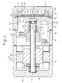
- a cylinder block 13 and a motor housing 15 are connected to a swash plate housing 12 that accommodates a swash plate 11.
- a chamber-forming housing 14 is connected to the cylinder block 13.
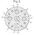
- the motor housing 15, the swash plate housing 12, the cylinder block 13, and the chamber-forming housing 14 are fixed together by the fastening of screws 10 (shown in Fig. 2 and Fig. 3).
- the motor housing 15 and the cylinder block 13 rotatably supports a rotary shaft 16 via radial bearings 17 and 18.
- the rotary shaft 16 plunges into a supporting hole 132 formed on the cylinder block 13.
- the radial bearing 17 supports the rotary shaft 16 within the supporting hole 132.
- the rotary shaft 16 passes through an end wall 121 of the swash plate housing 12, and into a supporting hole 151 formed on the motor housing 15.
- the radial bearing 18 supports the rotary shaft 16 within the supporting hole 151.
- the swash plate 11 is fixed to the rotary shaft 16 within the swash plate housing 12.
- a stator 19 is fitted to the inner peripheral surface of the motor housing 15, and a rotor 20 is fixed to the rotary shaft 16 within the motor housing 15.
- the rotary shaft 16 is pressed into the rotor 20 having a cylindrical shape. It is needless to mention that a key engagement is provided to effect an integrated rotation of the rotor 20 and the rotary shaft 16.
- the rotor 20 rotates based on a current conduction to the stator 19, and the rotary shaft 16 integrally rotates with the rotor 20.
- the stator 19 and the rotor 20 constitute a motor 21.
- a plurality of cylinder bores 131 are formed on the cylinder block 13.
- the plurality of cylinder bores 131 are laid out at equal intervals around the rotary shaft 16.
- a single-headed piston 22 is accommodated within each cylinder bore 131.
- shoes 23 exist between the swash plate 11 and each single-headed piston 22. The rotational force of the swash plate 11 is transmitted to the single-headed piston 22 via the shoes 23, and each single-headed piston 22 makes a reciprocating motion within each cylinder bore 131 accompanied by the rotation of the swash plate 11.
- a valve plate 24 and a valve forming plate 25 are disposed between the chamber-forming housing 14 and the cylinder block 13.
- the space inside the chamber-forming housing 14 is separated into a suction chamber 142 and a discharge chamber 143 by a partition 141.
- a valve forming plate 26 and a retainer 27 are caulked on the valve plate 24 with a pin 28.
- a suction port 241 is formed corresponding to the suction chamber 142 and each cylinder bore 131.
- a discharge port 242 is formed corresponding to the discharge chamber 143 and each cylinder bore 131.
- a suction valve 251 is formed on the valve forming plate 25, and a discharge valve 261 is formed on the valve forming plate 26. The suction valve 251 opens and closes the suction port 241, and the discharge valve 261 opens and closes the discharge port 242.
- the refrigerant within the suction chamber 142 pushes aside the suction valve 251 based on a backward motion of each single-headed'piston 22 (a move from the right to the left in Fig. 1), and flows into each cylinder bore 131 through the suction port 241.
- the refrigerant that has flown into each cylinder bore 131 pushes aside the discharge valve 261 based on a forward motion of the single-headed piston 242 (a move from the left to the right in Fig. 1), and is discharged to the discharge chamber 143 through the discharge port 242.
- the discharge valve 261 is brought into contact with the retainer 27, and the retainer 27 restricts the degree of the opening of the discharge valve 261.
- the suction chamber 142 and the discharge chamber 143 are connected together by an external refrigerant circuit not shown.
- the refrigerant that has flown out of the discharge chamber 143 into the external refrigerant circuit flows back to the suction chamber 142 through a condenser, an expansion valve, and an evaporator disposed on the external refrigerant circuit.
- Carbon dioxide is used as the refrigerant in the present embodiment.
- a thrust bearing 29 exists between a cylindrical base 111 of the swash plate 11 and an end wall 121 of the swash plate housing 12.
- the thrust bearing 29 surrounds the rotary shaft 16.
- a step 161 is formed at the end of the rotary shaft 16 that plunges into the supporting hole 132.
- a thrust bearing 30 and a belleville spring 31 exist between the step 161 and the bottom surface of the supporting hole 132.
- the spring force of the belleville spring 31 biases the rotary shaft 16 toward the motor housing 15 via the thrust bearing 30.
- the end wall 121 receives the spring force of the belleville spring 31 via the thrust bearing 30, the rotary shaft 16, the swash plate 11, and the thrust bearing 29.
- thrust bearing 29A that becomes the thrust load receiving means is provided within the motor housing 15.
- the thrust bearing 29A exists between the end wall 152 of the motor housing 15 and the end surface of the rotor 20.
- the compressive reaction force when the single-headed piston 22 makes a forward motion is transmitted to the thrust bearing 29A via the swash plate 11, the rotary shaft 16, and the rotor 20.
- the thrust bearing 29A receives the compressive reaction force when the single-headed piston 22 makes the forward motion.
- the spring force of the belleville spring 31 is transmitted to the thrust bearing 29A via the rotary shaft 16 and the rotor 20, and the thrust bearing 29A receives the spring force of the belleville spring 31.
- the thrust bearing 29A is built in a space within the motor housing 15.
- the motor housing 15 does not become larger than that of the first embodiment.
- a member for supporting the thrust bearing 29 required in the first embodiment is unnecessary in the second embodiment, as the thrust bearing 29 is not required in the second embodiment. Therefore, the end wall 121 that is required in the first embodiment is unnecessary in the second embodiment. As a result, the swash plate housing 12 becomes smaller. Therefore, the thrust bearing 29A that uses the end wall 152 of the motor housing 15 as the receiver is thrust load receiving means suitable for providing a compact motor-operated compressor.
- the motor housing 15 is connected to the chamber-forming housing 14.
- the rotary shaft 16 passes through the end wall 144 of the chamber-forming housing 14, the valve plate 24, and the cylinder block 13.
- the rotary shaft 16 is rotatably supported by the end wall 121 of the swash plate housing 12 via a radial bearing 17A, and is also rotatably supported by the end wall 152 of the motor housing 15 via a radial hearing 18.
- a reference number 321 denotes a discharge valve formed on the valve forming plate 32, and 33 denotes a retainer for restricting the degree of the opening of the discharge valve 321.
- a belleville spring 31 that becomes a preload adding means is disposed between the bottom surface of the supporting hole 151 of the motor housing 15 and the end surface of the rotary shaft 16.
- each single-headed piston 22 During a backward motion of each single-headed piston 22 (a move from the left to the right in Fig. 5), the refrigerant (carbon dioxide) within the suction chamber 142 flows into each cylinder bore 131 through the retainer 33, the valve forming plate 32, and the suction port 241 that are formed on the valve plate 24.
- the refrigerant within the cylinder bore 131 is discharged to the discharge chamber 143 via the discharge port 242.
- the refrigerant within the discharge chamber 143 flows out into the external refrigerant circuit through a through hole 145 on the end wall 144 of the chamber-forming housing 14, the space inside the motor housing 15, and a discharge passage 153 on the end wall 152.
- the thrust bearing 29 receives the compressive reaction force generated by the forward motion of the single-headed piston 22 and the spring force of the belleville spring 31.
- the temperature of the refrigerant sent from the discharge chamber 143 to the inside of the motor housing 15 is lower than the temperature of the motor 21. Therefore, there is an advantage that the motor 21 is cooled by the discharge refrigerant.
- the belleville spring 31 as the preload adding means and the thrust bearing 30 are disposed between the end surface of the cylinder block 13 and the base 111 of the swash plate 11.
- the spring force of the belleville spring 31 directly presses the swash plate 11 toward the thrust bearing 29 to abut each other. Therefore, it is possible to employ such a structure that the swash plate 11 can slide to the axial direction of the rotary shaft 16 and the swash plate 11 integrally rotates with the rotary shaft 16.
- a semispherical supporting recess 154 is formed on the end wall 152 of the motor housing 15, and a semispherical supporting recess 162 is formed on the end surface of the rotary shaft 16.
- a sphere 34 is provided rotatably between the supporting recesses 154 and 162. The sphere 34 receives the compressive reaction force and the spring force of the belleville spring 31 via the rotary shaft 16. The sphere 34 disposed within the motor housing 15 becomes thrust load receiving means.
- a rotary shaft is driven by a motor in a compressor that reciprocally moves a single-headed piston by transmitting the rotation force of a swash plate to the piston via shoes. Therefore, there is an excellent effect that it is possible to make compact the motor-operated compressor.
Landscapes
- Engineering & Computer Science (AREA)
- Mechanical Engineering (AREA)
- General Engineering & Computer Science (AREA)
- Manufacturing & Machinery (AREA)
- Compressors, Vaccum Pumps And Other Relevant Systems (AREA)
Abstract
Description
Claims (8)
- A motor-operated compressor that accommodates a piston within each of a plurality of cylinder bores laid out around a rotary shaft, and that has a shoe disposed between a swash plate that rotates integrally with said rotary shaft and each piston so that said shoe is in a sliding contact with both said swash plate and said piston, thereby to reciprocally move said piston by transmitting the rotational force of said swash plate to the piston via said shoe, wherein
said piston for making a reciprocating motion is a single-headed piston that discharges a gas from said cylinder bores only during a forward motion, and said rotary shaft is driven by a motor. - The motor-operated compressor according to Claim 1, wherein said swash plate has an invariable inclined angle with respect to said rotary shaft.
- The motor-operated compressor according to Claim 1, whereinsaid swash plate is accommodated within a swash plate housing,thrust load receiving means are provided at a side opposite to said cylinder bores with said swash plate as a boundary within said swash plate housing, andsaid thrust load receiving means receives the compressive reaction force when said single-headed piston makes a reciprocating motion.
- The motor-operated compressor according to Claim 1, whereinsaid motor is accommodated within a motor housing,thrust load receiving means are provided at a side opposite to said cylinder bores with said swash plate as a boundary within said motor housing, andsaid thrust load receiving means receives the compressive reaction force when said single-headed piston makes a reciprocating motion.
- The motor-operated compressor according to Claim 3, wherein said thrust load receiving means is a thrust bearing.
- The motor-operated compressor according to Claim 3, wherein there is provided preload adding means for biasing said swash plate toward said thrust load receiving means, and said thrust load receiving means receives a preload added to said swash plate by said preload adding means.
- The motor-operated compressor according to Claim 4, wherein there is provided preload adding means for biasing said swash plate toward said thrust load receiving means, and said thrust load receiving means receives preload added to said swash plate by said preload adding means.
- The motor-operated compressor according to Claim 1, wherein said gas is carbon dioxide.
Applications Claiming Priority (5)
| Application Number | Priority Date | Filing Date | Title |
|---|---|---|---|
| JP28253099A JP2001099059A (en) | 1999-10-04 | 1999-10-04 | Piston type compressor |
| JP28253099 | 1999-10-04 | ||
| JP36969399A JP2001182649A (en) | 1999-12-27 | 1999-12-27 | Motor-driven compressor |
| JP36969399 | 1999-12-27 | ||
| PCT/JP2000/006889 WO2001025636A1 (en) | 1999-10-04 | 2000-10-03 | Electric compressor |
Publications (2)
| Publication Number | Publication Date |
|---|---|
| EP1136700A1 true EP1136700A1 (en) | 2001-09-26 |
| EP1136700A4 EP1136700A4 (en) | 2005-04-27 |
Family
ID=26554643
Family Applications (1)
| Application Number | Title | Priority Date | Filing Date |
|---|---|---|---|
| EP00963085A Withdrawn EP1136700A4 (en) | 1999-10-04 | 2000-10-03 | Electric compressor |
Country Status (3)
| Country | Link |
|---|---|
| US (1) | US6609897B1 (en) |
| EP (1) | EP1136700A4 (en) |
| WO (1) | WO2001025636A1 (en) |
Families Citing this family (4)
| Publication number | Priority date | Publication date | Assignee | Title |
|---|---|---|---|---|
| US20060239833A1 (en) * | 2003-04-23 | 2006-10-26 | Taeyoung Park | Motor driven compressor |
| US7028475B2 (en) | 2003-05-20 | 2006-04-18 | Denso Corporation | Fluid machine |
| CN102265030B (en) | 2010-03-15 | 2014-12-17 | 三菱重工业株式会社 | Wind power generator and cable support structure for use in same |
| CN115199680B (en) * | 2022-07-08 | 2024-03-19 | 潍柴动力股份有限公司 | A forced release braking device and method for a walking motor |
Family Cites Families (14)
| Publication number | Priority date | Publication date | Assignee | Title |
|---|---|---|---|---|
| GB1433440A (en) * | 1974-07-30 | 1976-04-28 | Sundstrand Corp | Refrigeration compressor |
| JP3298126B2 (en) | 1992-01-14 | 2002-07-02 | 株式会社日立製作所 | Refrigerant compressor |
| JPH05231311A (en) | 1992-02-20 | 1993-09-07 | Hitachi Ltd | Variable displacement swash plate compressor |
| JP2596291B2 (en) | 1992-09-16 | 1997-04-02 | 富士電気化学株式会社 | Method of manufacturing coin-shaped lithium battery |
| JP2596291Y2 (en) * | 1993-06-01 | 1999-06-07 | カルソニック株式会社 | Hybrid compressor |
| JPH0942156A (en) | 1995-07-25 | 1997-02-10 | Mitsubishi Heavy Ind Ltd | Motor compressor |
| JPH10259830A (en) * | 1997-03-21 | 1998-09-29 | Toyota Autom Loom Works Ltd | Power transmission structure |
| DE19830312B4 (en) * | 1997-07-09 | 2005-05-12 | Denso Corp., Kariya | By a combustion and electric motor driven hybrid compressor |
| JP3968841B2 (en) * | 1997-12-24 | 2007-08-29 | 株式会社デンソー | Refrigeration cycle |
| US6280151B1 (en) * | 1998-03-09 | 2001-08-28 | Kabushiki Kaisha Toyoda Jidoshokki Seisakusho | Single-ended swash plate compressor |
| JPH11257219A (en) | 1998-03-09 | 1999-09-21 | Toyota Autom Loom Works Ltd | Single-sided swash plate type compressor |
| DE19912006A1 (en) * | 1998-03-17 | 1999-09-30 | Luk Fahrzeug Hydraulik | Compressor, particularly for motor vehicle air-conditioning plant |
| JPH11287182A (en) | 1998-04-02 | 1999-10-19 | Calsonic Corp | Compressor for vehicle air conditioner |
| JP3925007B2 (en) * | 1999-10-12 | 2007-06-06 | 株式会社豊田自動織機 | Piston rotation restriction structure in a compressor |
-
2000
- 2000-10-03 WO PCT/JP2000/006889 patent/WO2001025636A1/en not_active Ceased
- 2000-10-03 US US09/831,990 patent/US6609897B1/en not_active Expired - Fee Related
- 2000-10-03 EP EP00963085A patent/EP1136700A4/en not_active Withdrawn
Also Published As
| Publication number | Publication date |
|---|---|
| WO2001025636A1 (en) | 2001-04-12 |
| US6609897B1 (en) | 2003-08-26 |
| EP1136700A4 (en) | 2005-04-27 |
Similar Documents
| Publication | Publication Date | Title |
|---|---|---|
| US6565329B2 (en) | Electric type swash plate compressor | |
| US5765464A (en) | Reciprocating pistons of piston-type compressor | |
| US5615599A (en) | Guiding mechanism for reciprocating piston of piston-type compressor | |
| EP0809024B1 (en) | Reciprocating pistons of piston type compressor | |
| US6203284B1 (en) | Valve arrangement at the discharge chamber of a variable displacement compressor | |
| EP1260711A2 (en) | Compressor provided with sliding bearing | |
| US4730987A (en) | Variable delivery compressor | |
| US6609897B1 (en) | Motor-operated compressor | |
| US6544004B2 (en) | Single-headed piston type compressor | |
| CA2221475C (en) | Variable displacement compressor | |
| US5201189A (en) | Refrigerant compressor with an initial seizure prevention means | |
| US6293182B1 (en) | Piston-type compressor with piston guide | |
| EP1118769A2 (en) | Swash plate type compressor | |
| US20030059316A1 (en) | Multistage type piston compressor | |
| US5890878A (en) | Valve structure in compressor | |
| CN111656012A (en) | Variable capacity swash plate compressor | |
| KR100614023B1 (en) | Variable displacement compressor | |
| CN104948416B (en) | Variable displacement rotary slope plate type compressor | |
| KR20150112840A (en) | Variable displacement swash plate compressor | |
| JP2001182649A (en) | Motor-driven compressor | |
| US11994119B2 (en) | Compressor | |
| JP2000161207A (en) | Variable capacity swash plate type compressor | |
| US6398519B1 (en) | Swash plate compressor including a connection mechanism between a piston and an inside surface of a crank chamber | |
| CN104948415B (en) | Variable displacement swash plate compressor | |
| US20010043866A1 (en) | Electric compressor |
Legal Events
| Date | Code | Title | Description |
|---|---|---|---|
| PUAI | Public reference made under article 153(3) epc to a published international application that has entered the european phase |
Free format text: ORIGINAL CODE: 0009012 |
|
| 17P | Request for examination filed |
Effective date: 20010518 |
|
| AK | Designated contracting states |
Kind code of ref document: A1 Designated state(s): AT BE CH CY DE DK ES FI FR GB GR IE IT LI LU MC NL PT SE |
|
| RAP1 | Party data changed (applicant data changed or rights of an application transferred) |
Owner name: KABUSHIKI KAISHA TOYOTA JIDOSHOKKI |
|
| RBV | Designated contracting states (corrected) |
Designated state(s): DE FR IT |
|
| STAA | Information on the status of an ep patent application or granted ep patent |
Free format text: STATUS: THE APPLICATION HAS BEEN WITHDRAWN |
|
| A4 | Supplementary search report drawn up and despatched |
Effective date: 20050314 |
|
| RIC1 | Information provided on ipc code assigned before grant |
Ipc: 7F 04B 27/10 A Ipc: 7F 04B 35/04 B Ipc: 7F 04B 27/08 B |
|
| 18W | Application withdrawn |
Effective date: 20050402 |