EP1136665A2 - Handheld type four-cycle engine - Google Patents
Handheld type four-cycle engine Download PDFInfo
- Publication number
- EP1136665A2 EP1136665A2 EP01106698A EP01106698A EP1136665A2 EP 1136665 A2 EP1136665 A2 EP 1136665A2 EP 01106698 A EP01106698 A EP 01106698A EP 01106698 A EP01106698 A EP 01106698A EP 1136665 A2 EP1136665 A2 EP 1136665A2
- Authority
- EP
- European Patent Office
- Prior art keywords
- oil
- oil tank
- valve
- chamber
- valve operation
- Prior art date
- Legal status (The legal status is an assumption and is not a legal conclusion. Google has not performed a legal analysis and makes no representation as to the accuracy of the status listed.)
- Granted
Links
Images


Classifications
-
- F—MECHANICAL ENGINEERING; LIGHTING; HEATING; WEAPONS; BLASTING
- F01—MACHINES OR ENGINES IN GENERAL; ENGINE PLANTS IN GENERAL; STEAM ENGINES
- F01M—LUBRICATING OF MACHINES OR ENGINES IN GENERAL; LUBRICATING INTERNAL COMBUSTION ENGINES; CRANKCASE VENTILATING
- F01M1/00—Pressure lubrication
- F01M1/04—Pressure lubrication using pressure in working cylinder or crankcase to operate lubricant feeding devices
-
- F—MECHANICAL ENGINEERING; LIGHTING; HEATING; WEAPONS; BLASTING
- F01—MACHINES OR ENGINES IN GENERAL; ENGINE PLANTS IN GENERAL; STEAM ENGINES
- F01L—CYCLICALLY OPERATING VALVES FOR MACHINES OR ENGINES
- F01L1/00—Valve-gear or valve arrangements, e.g. lift-valve gear
- F01L1/02—Valve drive
- F01L1/024—Belt drive
-
- F—MECHANICAL ENGINEERING; LIGHTING; HEATING; WEAPONS; BLASTING
- F01—MACHINES OR ENGINES IN GENERAL; ENGINE PLANTS IN GENERAL; STEAM ENGINES
- F01M—LUBRICATING OF MACHINES OR ENGINES IN GENERAL; LUBRICATING INTERNAL COMBUSTION ENGINES; CRANKCASE VENTILATING
- F01M11/00—Component parts, details or accessories, not provided for in, or of interest apart from, groups F01M1/00 - F01M9/00
- F01M11/06—Means for keeping lubricant level constant or for accommodating movement or position of machines or engines
- F01M11/062—Accommodating movement or position of machines or engines, e.g. dry sumps
- F01M11/064—Movement
-
- F—MECHANICAL ENGINEERING; LIGHTING; HEATING; WEAPONS; BLASTING
- F01—MACHINES OR ENGINES IN GENERAL; ENGINE PLANTS IN GENERAL; STEAM ENGINES
- F01M—LUBRICATING OF MACHINES OR ENGINES IN GENERAL; LUBRICATING INTERNAL COMBUSTION ENGINES; CRANKCASE VENTILATING
- F01M9/00—Lubrication means having pertinent characteristics not provided for in, or of interest apart from, groups F01M1/00 - F01M7/00
- F01M9/06—Dip or splash lubrication
-
- F—MECHANICAL ENGINEERING; LIGHTING; HEATING; WEAPONS; BLASTING
- F02—COMBUSTION ENGINES; HOT-GAS OR COMBUSTION-PRODUCT ENGINE PLANTS
- F02B—INTERNAL-COMBUSTION PISTON ENGINES; COMBUSTION ENGINES IN GENERAL
- F02B63/00—Adaptations of engines for driving pumps, hand-held tools or electric generators; Portable combinations of engines with engine-driven devices
- F02B63/02—Adaptations of engines for driving pumps, hand-held tools or electric generators; Portable combinations of engines with engine-driven devices for hand-held tools
-
- F—MECHANICAL ENGINEERING; LIGHTING; HEATING; WEAPONS; BLASTING
- F02—COMBUSTION ENGINES; HOT-GAS OR COMBUSTION-PRODUCT ENGINE PLANTS
- F02B—INTERNAL-COMBUSTION PISTON ENGINES; COMBUSTION ENGINES IN GENERAL
- F02B75/00—Other engines
- F02B75/02—Engines characterised by their cycles, e.g. six-stroke
- F02B2075/022—Engines characterised by their cycles, e.g. six-stroke having less than six strokes per cycle
- F02B2075/027—Engines characterised by their cycles, e.g. six-stroke having less than six strokes per cycle four
-
- F—MECHANICAL ENGINEERING; LIGHTING; HEATING; WEAPONS; BLASTING
- F02—COMBUSTION ENGINES; HOT-GAS OR COMBUSTION-PRODUCT ENGINE PLANTS
- F02B—INTERNAL-COMBUSTION PISTON ENGINES; COMBUSTION ENGINES IN GENERAL
- F02B2275/00—Other engines, components or details, not provided for in other groups of this subclass
- F02B2275/34—Lateral camshaft position
Definitions
- the present invention relates to a handheld type four-cycle engine which is mainly used as a power source for portable working apparatus such as a trimmer. More particularly, it relates to improvement of the so-called OHV engine that includes an engine main body, the engine main body including a crankcase having a crank chamber, a cylinder block having a cylinder bore, and a cylinder head having an intake port and an exhaust port; a crankshaft supported in the crankcase and housed inside the crank chamber; a piston fitted in the cylinder bore and connected to the crankshaft; an intake valve and an exhaust valve for opening and closing the intake port and exhaust port, the intake valve and exhaust valve being mounted in the cylinder head; and a valve operation mechanism operable in association with the rotation of the crankshaft so as to open and close the intake valve and exhaust valve.
- Japanese Patent Application Laid-open No. 10-288019 discloses one in which an oil reservoir is provided in the lower part of a crankcase, an oil mist is generated by scattering the oil stored in the oil reservoir by the rotation of a crankshaft, and the inside of the engine is lubricated with the oil mist.
- OHV engines having intake and exhaust valves in their cylinder head tend to be large in overall height due to the presence of the intake and exhaust valves and a valve operation mechanism for opening and closing them.
- an oil reservoir is formed in the lower part of the crankcase as in the above-mentioned conventional engine, the overall height is further increased and it becomes difficult to make the engine more compact.
- the present invention has been carried out in view of the above-mentioned circumstances. It is an object of the present invention to lubricate the inside of the crank chamber and the valve operation mechanism reliably regardless of the operational position of the engine, while reducing the overall height of the engine so making it more compact.
- a handheld type four-cycle engine including an engine main body, the engine main body including a crankcase having a crank chamber, a cylinder block having a cylinder bore, and a cylinder head having an intake port and an exhaust port; a crankshaft supported in the crankcase and housed inside the crank chamber; a piston fitted inside the cylinder bore and connected to the crankshaft; an intake valve and an exhaust valve for opening and closing the intake port and exhaust port, the intake valve and the exhaust valve being mounted in the cylinder head; and a valve operation mechanism operable in association with the rotation of the crankshaft so as to open and close the intake valve and the exhaust valve, wherein an oil tank for storing oil is provided so as to be connected to one side wall running the length of the crankcase and the cylinder block; the oil tank houses oil mist generation means for generating an oil mist from the stored oil, and a rotational movement section of the valve operation mechanism; the oil tank and
- the oil tank is provided so as to be connected to one side wall running the length of the crankcase and the cylinder block, it is unnecessary to provide an oil reservoir in the lower part of the crankcase, and the overall height of the engine can thus be reduced and the engine can be made more compact.
- the rotational section of the valve operation mechanism provided inside the oil tank can be lubricated with the oil mist particularly well.
- the oil mist inside the oil tank is supplied to the crank chamber and the valve operation chamber, and returned to the oil tank by utilising the pressure pulsations of the crank chamber, the inside of the crank chamber and the reciprocating movement section of the valve operation mechanism can be lubricated regardless of the operational position of the engine, and it is unnecessary to employ a special oil pump for circulating the oil mist so simplifying the structure.
- the oil mist generation means can be obtained in a simple manner.
- Figs. 1 to 4 illustrate a first embodiment of the present invention.
- Fig. 1 is an perspective view showing one embodiment of the handheld type four-cycle engine of the present invention in practical use.
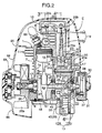
- Fig. 2 is a vertically sectioned front view of the above-mentioned four-cycle engine.
- Fig. 3 is a cross-sectional view at line 3-3 in Fig. 2.
- Fig. 4 is a cross-sectional view at line 4-4 in Fig. 2.
- Fig. 5 is a cross-sectional view corresponding to Fig. 4 and illustrating a second embodiment of the present invention.
- Fig. 6 is a cross-sectional view corresponding to Fig. 4 and illustrating a third embodiment of the present invention.
- a handheld type four-cycle engine E to which the present invention is applied is fitted as the source of power to the drive section of, for example, a powered trimmer T, Since the powered trimmer T is used in a manner in which a cutter C is positioned in various directions according to the operational conditions, the engine E is also tilted to a large extent or turned upside-down as a result and the operational position is unstable.
- the engine main body 1 of the above-mentioned handheld type four-cycle engine E includes a crankcase 6 having a crank chamber 6a, a cylinder block 7 having one cylinder bore 7a, and a cylinder head 8 having a combustion chamber 8a, a large number of cooling fins 11 being formed on the outer peripheries of the cylinder block 7 and the cylinder head 8.
- a crankshaft 12 housed in the crank chamber 6a is rotatably supported in left and right side walls of the crankcase 6 via ball bearings 14 and 14' and is also connected to a piston 15 fitted in the cylinder bore 7a via a connecting rod 16.
- An oil seal 17 is fitted in the left-hand side wall of the crankcase 6 so as to adjoin the outside of the bearing 14, a flywheel 26 having a large number of cooling vanes 26a is fixed to the left-hand end of the crankshaft 12 running through the oil seal 17 and projecting out of the crankcase 6, the flywheel 26 functioning also as a cooling fan, and a recoil type starter 64 is positioned outside the flywheel 26.
- An oil tank 13 is provided so as to be connected to the right-hand side wall running the length of the crankcase 6 and the cylinder block 7.
- a fuel tank 5 is provided on one side of the oil tank 13 and beneath a carburettor 2 and an air cleaner 4 which will be described below.
- the oil tank 13 includes a tank inner half 13a and a tank outer half 13b, the tank inner half 13a being integrally provided over the crankcase 6 and the cylinder block 7, and the tank outer half 13b being bolt-joined to the tank inner half 13a.
- the right-hand end of the crankshaft 12 runs through and projects out of the oil tank 13, An oil seal 17' in close contact with the outer circumference of the crankshaft 12 is fitted in the tank outer half 13b.
- a drive plate 27 is fixed to the right-hand end of the crankshaft 12 projecting out of the oil tank 13, and a plurality of centrifugal shoes 28 (one thereof is shown in the figure) are pivotally supported on the drive plate 27 in a rockable manner.
- An engine cover 65 is fixed to the engine main body 1 so as to cover it, a recoil type starter 64 is supported in the cover 65, and an air inlet 66 is provided in the engine cover 65 around the recoil type starter 64 so as to face the cooling vanes 26a of the flywheel 26.
- An intake port 9i and an exhaust port 9e opening into the combustion chamber 8a are formed in the cylinder head 8, and the cylinder head 8 is also provided with an intake valve 18i and an exhaust valve 18e and an ignition plug 63, the intake valve 18i and the exhaust valve 18e opening and closing the intake port 9i and the exhaust port 9e, and the electrodes of the ignition plug 63 extending into the combustion chamber 8a.
- a rocker chamber 19a whose upper face is blocked by a head cover 10 is provided in the cylinder head 8
- a pushrod chamber 19b extending from one side of the rocker chamber 19a down to the top of the oil tank 13 is formed in one side wall of the cylinder block 7, and the rocker chamber 19a and the pushrod chamber 19b together form a valve operation chamber 19.
- a valve operation mechanism 25 for closing and opening the intake and exhaust valves 18i and 18e is provided running through the valve operation chamber 19 and the oil tank 13.
- the valve operation mechanism 25 includes a rotational movement section 25a housed in the oil tank 13 and a reciprocating movement section 25b housed in the valve operation chamber 19.
- the rotational movement section 25a includes a drive gear 32 fixed to the crankshaft 12, a cam gear 36 rotatably supported on a support shaft 33 and meshed with the drive gear 32, the two ends of the support shaft 33 being supported in the oil tank 13, and an intake cam 211 and an exhaust cam 21e formed integrally with the cam gear 36, and the cam gear 36 is driven by the drive gear 32 at a reduction rate of 1/2.
- the drive gear 32 and the cam gear 36 are positioned above the crankshaft 12 and close to the outside wall of the oil tank 13.
- the reciprocating movement section 25b includes valve springs 20i and 20e forcing the intake and exhaust valves 18i and 18e respectively in the closed direction, rocker arms 22i and 22e supported in a rockable manner in the cylinder head 8, one end of each of the rocker arms 22i and 22e being in contact with the corresponding upper ends of the intake and exhaust valves 18i and 18e, and pushrods 23i and 23e (see Fig. 4), the upper end of each of the pushrods 23i and 23e being in contact with the corresponding other ends of the rocker arms 22i and 22e.
- the rocker arms 22i and 22e are housed in the rocker chamber 19a, and the pushrods 23i and 23e are housed in the pushrod chamber 19b.
- Tappets 24i and 24e receiving the lower end of each of the pushrods 23i and 23e and engaging with the intake and exhaust cams 21i and 21e respectively are fitted in a sliceable manner in guide holes 43 and 43 in a partition wall 42 between the pushrod chamber 19b and the oil tank 13.
- the engine E is thus constructed as an OHV type.
- the intake port 9i is connected to a carburettor 2 and an air cleaner 4 in that order, and the exhaust port 9e is connected to an exhaust muffler 3.
- the carburettor 2 and the exhaust muffler 3 are placed along a direction perpendicular to the axes of both the crankshaft 12 and the cylinder bore 7a.
- each of two support shafts 34 and 35 arranged around and beneath the crankshaft 12 is supported in the oil tank 13, and toothed oil slingers 37 and 38 meshed with the above-mentioned drive gear 32 are rotatably supported on the support shafts 34 and 35.
- These toothed oil slingers 37 and 38 are positioned close to the outside wall of the oil tank 13 in the same way as the cam gear 36, and vane type oil slingers 39 and 40 positioned close to the inside wall of the oil tank 13 are joined integrally to the corresponding toothed oil slingers 37 and 38 via bosses.
- the above-mentioned cam gear 36 and the two toothed oil slingers 37 and 38 are positioned with equal intervals therebetween around the crankshaft 12.
- the peripheral wall of the oil tank 13 is formed in a circular shape so as to surround these gears 36 to 38, a predetermined amount of lubricating oil O is stored inside the oil tank 13, at least one of the cam gear 36, the toothed oil slingers 37 and 38 and the vane type oil slingers 39 and 40 around the drive gear 32 is partially immersed in the stored oil O regardless of the operational position of the engine E, and its rotation scatters the stored oil O so generating an oil mist.
- the cam gear 36 therefore also functions as part of the oil slingers around the drive gear 32.
- the route taken by the oil mist generated in the oil tank 13 includes an oil inlet 45 provided in the crankshaft 12 and providing communication between the oil tank 13 and the crank chamber 6a, a valve hole 47 provided in the base of the crank case 6, a valve chamber 48 formed in the lower part of the crankcase 6 and communicated with the crank chamber 6a via the above-mentioned valve hole 47, an oil feed passage 49 rising from one side of the valve chamber 48 and extending to the rocker chamber 19a through a side wall of the engine main body 1, the rocker chamber 19a, the pushrod chamber 19b, and an oil return passage 50 extending from the pushrod chamber 19b to the oil tank 13 through the outside wall of the oil tank 13.
- Open ends 45a and 50a of the above-mentioned oil inlet 45 and the oil return passage 50 inside the oil tank 13 are positioned so as to be always above the liquid level of the stored oil ⁇ regardless of the operational position of the engine E.
- the above-mentioned valve chamber 48 includes a one-way valve 51 in the form of a reed valve for blocking and unblocking the valve hole 47, and the one-way valve 51 opens so as to unblock the valve hole 47 when the pressure of the crank chamber 6a becomes positive and closes so as to block the valve hole 47 when the pressure becomes negative accompanying the descent and ascent respectively of the piston 15.
- a flat-shaped first breather chamber 53a forming the middle part of the oil return passage 50 is formed in the partition wall 42 between the valve operation chamber 19 and the oil tank 13, and the first breather chamber 53a is connected to a second breather chamber 53b via a link passage 54, the second breather chamber 53b being formed in the above-mentioned head cover 10.
- the second breather chamber 53b is communicated with the above-mentioned air cleaner 4 on one side via a first orifice 55a and a breather pipe 56, and with the rocker chamber 19a on the other side via a plurality of second orifices 55b which open at different positions and are in different directions from each other.
- the valve operation mechanism 25 When the drive gear 32 rotates together with the crankshaft 12 during operation of the engine E, the valve operation mechanism 25 is operated as mentioned above, and at the same time, the cam gear 36, the toothed oil slingers 37 and 38, and the vane type oil slingers 39 and 40 all supported by the three support shafts 33, 34 and 35 rotate simultaneously. Since at least one of the cam gear 36, the toothed oil slingers 37 and 38, and the vane type oil slingers 39 and 40 scatters the stored oil O so generating an oil mist regardless of the operational position of the engine E, the oil tank 13 can always be filled with the oil mist. Since the rotational movement section 25a of the valve operation mechanism 25 is provided in such an oil tank 13, the rotational movement section 25a can be lubricated with the above-mentioned oil mist particularly well.
- a negative pressure and a positive pressure are generated alternately in the crank chamber 6a accompanying the ascent and descent of the piston 15 so causing pressure pulsations; when a negative pressure is generated, the one-way valve 51 closes so as to block the valve hole 47, and the oil mist inside the oil tank 13 is drawn up into the crank chamber 6a through the oil inlet 45 of the crankshaft 12 thus lubricating the crankshaft 12 and the piston 15. At this stage, the internal pressure of the oil tank 13 is reduced due to the oil mist drawn up into the crank chamber 6a.
- the oil liquefied inside the valve operation chamber 19 is transferred to the first breather chamber 53a from the upstream section of the oil return passage 50 together with the blowby gas, they are separated into gas and liquid in the first breather chamber 53a, the oil portion is returned into the oil tank 13 which is at a lower pressure via the downstream section of the oil return passage 50, and the blowby gas ascends inside the link passage 54 to enter the second breather chamber 53b, and is discharged into the air cleaner 4 via the second orifice 55b and the breather pipe 56.
- the blowby gas entering the second breather chamber 53b contains oil
- the oil is separated from the blowby gas in the second breather chamber 53b, and flows down through the link passage 54 or enters the valve operation chamber 19 via the second orifice 55b.
- the oil mist can thus be circulated from the oil tank 13 to the crank chamber 6a, the valve operation chamber 19, and back to the oil tank 13 by utilising the pressure pulsations of the crank chamber 6a, the inside of the engine E can be lubricated regardless of the operational position of the engine E, and it is unnecessary to employ a special oil pump.
- the rotational movement section 25a requiring a high level lubrication of the valve operation mechanism 25 is lubricated with a large amount of oil mist generated in the oil tank 13, the rotational movement section 25a can be lubricated well as required.
- the two toothed oil slingers 37 and 38 are placed immediately beside and immediately below the drive gear 32 respectively, and the peripheral wall of the oil tank 13 is generally made in the form of a D-shape around the oil slingers 37 and 38 and the cam gear 36, immediately above the drive gear 33. Since there is a comparatively large space outside the vertical wall 13w of the oil tank 13 so formed, a fuel tank 5 having a large capacity can be placed in this space.
- the two toothed oil slingers 37 and 38 are placed on either side of the drive gear 32 so as to be close to the cam gear 36 placed above the two oil slingers 37 and 38, and the peripheral wall of the oil tank 13 is made in the form of a rounded triangle around the cam gear 36 and the oil slingers 37 and 38,
- the oil tank 13 so formed has a shallow base, and since there is a flat space below the oil tank 13, an L-shaped fuel tank 5 having a large capacity can be disposed from one side to the base of the oil tank 13.
- a rotary valve operable in association with the crankshaft 12 and operating so as to unblock the oil feed passage 49 when the piston 15 descends and to block the oil feed passage 49 when the piston 15 ascends can be provided instead of the one-way valve 51.
- an oil tank is provided so as to be connected to one side wall running the length of a crankcase and a cylinder block, the oil tank houses oil mist generation means to and a rotational movement section of a valve operation mechanism, and the oil mist generated in the oil tank is supplied from a crank chamber to a valve operation chamber of a cylinder head housing a reciprocating movement section of the valve operation mechanism, and is returned to the oil tank by utilising the pressure pulsations of the crank chamber and a one-way valve. It is thus possible to lubricate the inside of the crank chamber and the valve operation mechanism reliably regardless of the operational position of the handheld type OHV engine while reducing the overall height of the engine.
Landscapes
- Engineering & Computer Science (AREA)
- Mechanical Engineering (AREA)
- General Engineering & Computer Science (AREA)
- Chemical & Material Sciences (AREA)
- Combustion & Propulsion (AREA)
- Lubrication Of Internal Combustion Engines (AREA)
- Lubrication Details And Ventilation Of Internal Combustion Engines (AREA)
- Valve-Gear Or Valve Arrangements (AREA)
Abstract
Description
- The present invention relates to a handheld type four-cycle engine which is mainly used as a power source for portable working apparatus such as a trimmer. More particularly, it relates to improvement of the so-called OHV engine that includes an engine main body, the engine main body including a crankcase having a crank chamber, a cylinder block having a cylinder bore, and a cylinder head having an intake port and an exhaust port; a crankshaft supported in the crankcase and housed inside the crank chamber; a piston fitted in the cylinder bore and connected to the crankshaft; an intake valve and an exhaust valve for opening and closing the intake port and exhaust port, the intake valve and exhaust valve being mounted in the cylinder head; and a valve operation mechanism operable in association with the rotation of the crankshaft so as to open and close the intake valve and exhaust valve.
- As such an OHV engine which is already known, for example, Japanese Patent Application Laid-open No. 10-288019 discloses one in which an oil reservoir is provided in the lower part of a crankcase, an oil mist is generated by scattering the oil stored in the oil reservoir by the rotation of a crankshaft, and the inside of the engine is lubricated with the oil mist.
- Generally, OHV engines having intake and exhaust valves in their cylinder head tend to be large in overall height due to the presence of the intake and exhaust valves and a valve operation mechanism for opening and closing them. However, an oil reservoir is formed in the lower part of the crankcase as in the above-mentioned conventional engine, the overall height is further increased and it becomes difficult to make the engine more compact.
- The present invention has been carried out in view of the above-mentioned circumstances. It is an object of the present invention to lubricate the inside of the crank chamber and the valve operation mechanism reliably regardless of the operational position of the engine, while reducing the overall height of the engine so making it more compact.
- In accordance with a first aspect of the present invention in order to achieve the above-mentioned objective, there is proposed a handheld type four-cycle engine including an engine main body, the engine main body including a crankcase having a crank chamber, a cylinder block having a cylinder bore, and a cylinder head having an intake port and an exhaust port; a crankshaft supported in the crankcase and housed inside the crank chamber; a piston fitted inside the cylinder bore and connected to the crankshaft; an intake valve and an exhaust valve for opening and closing the intake port and exhaust port, the intake valve and the exhaust valve being mounted in the cylinder head; and a valve operation mechanism operable in association with the rotation of the crankshaft so as to open and close the intake valve and the exhaust valve, wherein an oil tank for storing oil is provided so as to be connected to one side wall running the length of the crankcase and the cylinder block; the oil tank houses oil mist generation means for generating an oil mist from the stored oil, and a rotational movement section of the valve operation mechanism; the oil tank and the crank chamber are communicated with each other above the stored oil in the oil tank; the crank chamber and a valve operation chamber formed in the cylinder head so as to house a reciprocating movement section of the valve operation mechanism are communicated with each other via an oil feed passage; the valve operation chamber and the oil tank are communicated with each other above the stored oil in the oil tank via an oil return passage; and transfer means for sending only the positive pressure component of pressure pulsations generated in the crank chamber towards the valve operation chamber is provided in the oil feed passage. The above-mentioned transfer means corresponds to the one-
way valve 51 in the embodiments of the present invention below. - In accordance with the above-mentioned first characteristic, since the oil tank is provided so as to be connected to one side wall running the length of the crankcase and the cylinder block, it is unnecessary to provide an oil reservoir in the lower part of the crankcase, and the overall height of the engine can thus be reduced and the engine can be made more compact.
- Furthermore, since the oil tank is filled with the oil mist generated by the oil mist generation means, the rotational section of the valve operation mechanism provided inside the oil tank can be lubricated with the oil mist particularly well.
- Moreover, since the oil mist inside the oil tank is supplied to the crank chamber and the valve operation chamber, and returned to the oil tank by utilising the pressure pulsations of the crank chamber, the inside of the crank chamber and the reciprocating movement section of the valve operation mechanism can be lubricated regardless of the operational position of the engine, and it is unnecessary to employ a special oil pump for circulating the oil mist so simplifying the structure.
- In accordance with a second aspect of the present invention, in addition to the above-mentioned characteristic, there is proposed a handheld type four-cycle engine wherein an oil mist is generated by the motion of the rotational movement section of the valve operation mechanism scattering the stored oil inside the oil tank.
- In accordance with the above-mentioned second characteristic, since the rotational section of the valve operation chamber functions as part of the oil mist generation means, the oil mist generation means can be obtained in a simple manner.
- The above-mentioned object, other objects, characteristics and advantages of the present invention will become apparent from an explanation of preferable embodiments which will be described in detail below by reference to the attached drawings.
- Figs. 1 to 4 illustrate a first embodiment of the present invention.
- Fig. 1 is an perspective view showing one embodiment of the handheld type four-cycle engine of the present invention in practical use.
- Fig. 2 is a vertically sectioned front view of the above-mentioned four-cycle engine.
- Fig. 3 is a cross-sectional view at line 3-3 in Fig. 2.
- Fig. 4 is a cross-sectional view at line 4-4 in Fig. 2.
- Fig. 5 is a cross-sectional view corresponding to Fig. 4 and illustrating a second embodiment of the present invention.
- Fig. 6 is a cross-sectional view corresponding to Fig. 4 and illustrating a third embodiment of the present invention.
- The first embodiment of the present invention shown in Figs. 1 to 4 is explained first.
- As shown in Fig. 1, a handheld type four-cycle engine E to which the present invention is applied is fitted as the source of power to the drive section of, for example, a powered trimmer T, Since the powered trimmer T is used in a manner in which a cutter C is positioned in various directions according to the operational conditions, the engine E is also tilted to a large extent or turned upside-down as a result and the operational position is unstable.
- As shown in Figs. 2 and 3, the engine
main body 1 of the above-mentioned handheld type four-cycle engine E includes a crankcase 6 having a crank chamber 6a, acylinder block 7 having onecylinder bore 7a, and acylinder head 8 having acombustion chamber 8a, a large number ofcooling fins 11 being formed on the outer peripheries of thecylinder block 7 and thecylinder head 8. - A
crankshaft 12 housed in the crank chamber 6a is rotatably supported in left and right side walls of the crankcase 6 viaball bearings 14 and 14' and is also connected to apiston 15 fitted in thecylinder bore 7a via a connectingrod 16. Anoil seal 17 is fitted in the left-hand side wall of the crankcase 6 so as to adjoin the outside of thebearing 14, aflywheel 26 having a large number ofcooling vanes 26a is fixed to the left-hand end of thecrankshaft 12 running through theoil seal 17 and projecting out of the crankcase 6, theflywheel 26 functioning also as a cooling fan, and arecoil type starter 64 is positioned outside theflywheel 26. - An
oil tank 13 is provided so as to be connected to the right-hand side wall running the length of the crankcase 6 and thecylinder block 7. Afuel tank 5 is provided on one side of theoil tank 13 and beneath acarburettor 2 and anair cleaner 4 which will be described below. - The
oil tank 13 includes a tankinner half 13a and a tankouter half 13b, the tankinner half 13a being integrally provided over the crankcase 6 and thecylinder block 7, and the tankouter half 13b being bolt-joined to the tankinner half 13a. The right-hand end of thecrankshaft 12 runs through and projects out of theoil tank 13, An oil seal 17' in close contact with the outer circumference of thecrankshaft 12 is fitted in the tankouter half 13b. - A
drive plate 27 is fixed to the right-hand end of thecrankshaft 12 projecting out of theoil tank 13, and a plurality of centrifugal shoes 28 (one thereof is shown in the figure) are pivotally supported on thedrive plate 27 in a rockable manner. Thesecentrifugal shoes 28, together with aclutch drum 30 connected to adrive shaft 29 for driving the aforementioned cutter C, form acentrifugal clutch 31 and when the rotational rate of thecrankshaft 12 exceeds a predetermined value, thecentrifugal shoes 28 are pressed onto the inner periphery of theclutch drum 30 due to the centrifugal force of the shoes so transmitting the output torque of thecrankshaft 12 to thedrive shaft 29. - An
engine cover 65 is fixed to the enginemain body 1 so as to cover it, arecoil type starter 64 is supported in thecover 65, and anair inlet 66 is provided in theengine cover 65 around therecoil type starter 64 so as to face thecooling vanes 26a of theflywheel 26. - An
intake port 9i and an exhaust port 9e opening into thecombustion chamber 8a are formed in thecylinder head 8, and thecylinder head 8 is also provided with anintake valve 18i and an exhaust valve 18e and anignition plug 63, theintake valve 18i and the exhaust valve 18e opening and closing theintake port 9i and the exhaust port 9e, and the electrodes of theignition plug 63 extending into thecombustion chamber 8a. - A
rocker chamber 19a whose upper face is blocked by ahead cover 10 is provided in thecylinder head 8, apushrod chamber 19b extending from one side of therocker chamber 19a down to the top of theoil tank 13 is formed in one side wall of thecylinder block 7, and therocker chamber 19a and thepushrod chamber 19b together form avalve operation chamber 19. Avalve operation mechanism 25 for closing and opening the intake andexhaust valves 18i and 18e is provided running through thevalve operation chamber 19 and theoil tank 13. - That is to say, the
valve operation mechanism 25 includes arotational movement section 25a housed in theoil tank 13 and areciprocating movement section 25b housed in thevalve operation chamber 19. Therotational movement section 25a includes adrive gear 32 fixed to thecrankshaft 12, acam gear 36 rotatably supported on asupport shaft 33 and meshed with thedrive gear 32, the two ends of thesupport shaft 33 being supported in theoil tank 13, and anintake cam 211 and anexhaust cam 21e formed integrally with thecam gear 36, and thecam gear 36 is driven by thedrive gear 32 at a reduction rate of 1/2. Thedrive gear 32 and thecam gear 36 are positioned above thecrankshaft 12 and close to the outside wall of theoil tank 13. - The
reciprocating movement section 25b includesvalve springs 20i and 20e forcing the intake andexhaust valves 18i and 18e respectively in the closed direction,rocker arms cylinder head 8, one end of each of therocker arms exhaust valves 18i and 18e, andpushrods pushrods rocker arms rocker arms rocker chamber 19a, and thepushrods pushrod chamber 19b.Tappets pushrods exhaust cams 21i and 21e respectively are fitted in a sliceable manner inguide holes partition wall 42 between thepushrod chamber 19b and theoil tank 13. - The engine E is thus constructed as an OHV type.
- When the intake and
exhaust cams 21i and 21e are rotated by thecrankshaft 12 via thedrive gear 32 and thecam gear 36, thesecams 21i and 21e work together with thevalve springs 20i and 20e, and allow thecorresponding pushrods rocker arms exhaust valves 18i and 18e are thus opened and closed alternately with appropriate timing. - As shown in Fig. 3, the
intake port 9i is connected to acarburettor 2 and anair cleaner 4 in that order, and the exhaust port 9e is connected to anexhaust muffler 3. Thecarburettor 2 and theexhaust muffler 3 are placed along a direction perpendicular to the axes of both thecrankshaft 12 and the cylinder bore 7a. - The lubrication system of the engine E is explained below by reference to Figs. 2 and 4.
- An end of each of two
support shafts crankshaft 12 is supported in theoil tank 13, andtoothed oil slingers drive gear 32 are rotatably supported on thesupport shafts toothed oil slingers oil tank 13 in the same way as thecam gear 36, and vanetype oil slingers oil tank 13 are joined integrally to the correspondingtoothed oil slingers - As shown in Fig. 4, the above-mentioned
cam gear 36 and the twotoothed oil slingers crankshaft 12. The peripheral wall of theoil tank 13 is formed in a circular shape so as to surround thesegears 36 to 38, a predetermined amount of lubricating oil O is stored inside theoil tank 13, at least one of thecam gear 36, thetoothed oil slingers type oil slingers drive gear 32 is partially immersed in the stored oil O regardless of the operational position of the engine E, and its rotation scatters the stored oil O so generating an oil mist. Thecam gear 36 therefore also functions as part of the oil slingers around thedrive gear 32. - The route taken by the oil mist generated in the
oil tank 13 includes an oil inlet 45 provided in thecrankshaft 12 and providing communication between theoil tank 13 and the crank chamber 6a, avalve hole 47 provided in the base of the crank case 6, avalve chamber 48 formed in the lower part of the crankcase 6 and communicated with the crank chamber 6a via the above-mentionedvalve hole 47, anoil feed passage 49 rising from one side of thevalve chamber 48 and extending to therocker chamber 19a through a side wall of the enginemain body 1, therocker chamber 19a, thepushrod chamber 19b, and anoil return passage 50 extending from thepushrod chamber 19b to theoil tank 13 through the outside wall of theoil tank 13.Open ends 45a and 50a of the above-mentioned oil inlet 45 and theoil return passage 50 inside theoil tank 13 are positioned so as to be always above the liquid level of the stored oil ○ regardless of the operational position of the engine E. - The above-mentioned
valve chamber 48 includes a one-way valve 51 in the form of a reed valve for blocking and unblocking thevalve hole 47, and the one-way valve 51 opens so as to unblock thevalve hole 47 when the pressure of the crank chamber 6a becomes positive and closes so as to block thevalve hole 47 when the pressure becomes negative accompanying the descent and ascent respectively of thepiston 15. - In Figs. 3 and 4, a flat-shaped
first breather chamber 53a forming the middle part of theoil return passage 50 is formed in thepartition wall 42 between thevalve operation chamber 19 and theoil tank 13, and thefirst breather chamber 53a is connected to asecond breather chamber 53b via alink passage 54, thesecond breather chamber 53b being formed in the above-mentionedhead cover 10. Thesecond breather chamber 53b is communicated with the above-mentionedair cleaner 4 on one side via a first orifice 55a and abreather pipe 56, and with therocker chamber 19a on the other side via a plurality ofsecond orifices 55b which open at different positions and are in different directions from each other. - The action of this embodiment is explained below.
- When the
drive gear 32 rotates together with thecrankshaft 12 during operation of the engine E, thevalve operation mechanism 25 is operated as mentioned above, and at the same time, thecam gear 36, thetoothed oil slingers type oil slingers support shafts cam gear 36, thetoothed oil slingers type oil slingers oil tank 13 can always be filled with the oil mist. Since therotational movement section 25a of thevalve operation mechanism 25 is provided in such anoil tank 13, therotational movement section 25a can be lubricated with the above-mentioned oil mist particularly well. - A negative pressure and a positive pressure are generated alternately in the crank chamber 6a accompanying the ascent and descent of the
piston 15 so causing pressure pulsations; when a negative pressure is generated, the one-way valve 51 closes so as to block thevalve hole 47, and the oil mist inside theoil tank 13 is drawn up into the crank chamber 6a through the oil inlet 45 of thecrankshaft 12 thus lubricating thecrankshaft 12 and thepiston 15. At this stage, the internal pressure of theoil tank 13 is reduced due to the oil mist drawn up into the crank chamber 6a. - When a positive pressure is generated, since the one-
way valve 51 opens so as to unblock thevalve hole 47, the oil mist inside the crank chamber 6a is discharged together with the blowby gas generated in the crank chamber 6a into therocker chamber 19a through thevalve hole 47, thevalve chamber 48 and theoil feed passage 49, so that the oil mist is spread over the entirevalve operation chamber 19, and thereciprocating movement section 25b of thevalve operation mechanism 25 can thus be lubricated. The oil mist is then liquefied. - The oil liquefied inside the
valve operation chamber 19 is transferred to thefirst breather chamber 53a from the upstream section of theoil return passage 50 together with the blowby gas, they are separated into gas and liquid in thefirst breather chamber 53a, the oil portion is returned into theoil tank 13 which is at a lower pressure via the downstream section of theoil return passage 50, and the blowby gas ascends inside thelink passage 54 to enter thesecond breather chamber 53b, and is discharged into theair cleaner 4 via thesecond orifice 55b and thebreather pipe 56. - In the case where the blowby gas entering the
second breather chamber 53b contains oil, the oil is separated from the blowby gas in thesecond breather chamber 53b, and flows down through thelink passage 54 or enters thevalve operation chamber 19 via thesecond orifice 55b. - Since the
second breather chamber 53b is connected to thebreather pipe 56 via the first orifice 55a, the first orifice 55a can minimise as much as possible the leakage of negative pressure of theoil tank 13 from thesecond breather chamber 53b towards thebreather pipe 56, and thus theoil tank 13 can always maintain its internal negative pressure rendered by the pressure pulsations of the crank chamber 6a during operation of the engine E. - The oil mist can thus be circulated from the
oil tank 13 to the crank chamber 6a, thevalve operation chamber 19, and back to theoil tank 13 by utilising the pressure pulsations of the crank chamber 6a, the inside of the engine E can be lubricated regardless of the operational position of the engine E, and it is unnecessary to employ a special oil pump. In particular, since therotational movement section 25a requiring a high level lubrication of thevalve operation mechanism 25 is lubricated with a large amount of oil mist generated in theoil tank 13, therotational movement section 25a can be lubricated well as required. - Since the
oil tank 13 is provided so as to be connected to one side wall running the length of the crankcase 6 and thecylinder block 7, it is unnecessary to provide an oil reservoir in the lower part of the crankcase 6, and the overall height of the engine E can be lessened and the size thereof can be reduced. - The second and third embodiments of the present invention are explained below by reference to Figs. 5 and 6.
- The second and third embodiments are different from the first embodiment in terms of the arrangement of the
toothed oil slingers drive gear 32, the shape of the peripheral wall of theoil tank 13, and the shape and arrangement of thefuel tank 5. - That is to say, in the second embodiment shown in Fig. 5, the two
toothed oil slingers drive gear 32 respectively, and the peripheral wall of theoil tank 13 is generally made in the form of a D-shape around theoil slingers cam gear 36, immediately above thedrive gear 33. Since there is a comparatively large space outside the vertical wall 13w of theoil tank 13 so formed, afuel tank 5 having a large capacity can be placed in this space. - In the third embodiment shown in Fig. 6, the two
toothed oil slingers drive gear 32 so as to be close to thecam gear 36 placed above the twooil slingers oil tank 13 is made in the form of a rounded triangle around thecam gear 36 and theoil slingers oil tank 13 so formed has a shallow base, and since there is a flat space below theoil tank 13, an L-shapedfuel tank 5 having a large capacity can be disposed from one side to the base of theoil tank 13. - The components in Figs. 5 and 6 corresponding to those in the first embodiment are denoted by the same reference numerals and are not explained.
- As is clear from the above-mentioned first to third embodiments, by selecting the positions of the
support shafts drive gear 32, that is to say, the positions of thecam gear 36 and thetoothed oil slingers oil tank 13 surrounding them can be changed freely, and the degree of freedom in the layout of equipment adjoining theoil tank 13 increase. - Moreover, since the
cam gear 36 and thetoothed oil slingers drive gear 32 in such a state that they are close to the peripheral wall of theoil tank 13, the stored oil O can be scattered by at least one of thecam gear 36 and thetoothed oil slingers - Since the
cam gear 36 functions as part of the oil slingers provided around the drivengear 32, the number of special oil slingers can be reduced and the structure can thus be simplified. - The present invention is not limited to the above-mentioned embodiments and can be modified in a variety of ways without departing from the spirit and scope of the invention. For example, a rotary valve operable in association with the
crankshaft 12 and operating so as to unblock theoil feed passage 49 when thepiston 15 descends and to block theoil feed passage 49 when thepiston 15 ascends can be provided instead of the one-way valve 51. - In a handheld type OHV engine, an oil tank is provided so as to be connected to one side wall running the length of a crankcase and a cylinder block, the oil tank houses oil mist generation means to and a rotational movement section of a valve operation mechanism, and the oil mist generated in the oil tank is supplied from a crank chamber to a valve operation chamber of a cylinder head housing a reciprocating movement section of the valve operation mechanism, and is returned to the oil tank by utilising the pressure pulsations of the crank chamber and a one-way valve. It is thus possible to lubricate the inside of the crank chamber and the valve operation mechanism reliably regardless of the operational position of the handheld type OHV engine while reducing the overall height of the engine.
Claims (2)
- A handheld type four-cycle engine includingan engine main body, the engine main body including a crankcase having a crank chamber, a cylinder block having a cylinder bore and a cylinder head having an intake port and an exhaust port;a crankshaft supported in the crankcase and housed inside the crank chamber;a piston fitted inside the cylinder bore and connected to the crankshaft;an intake valve and an exhaust valve for opening and closing the intake port and exhaust port, the intake valve and the exhaust valve being mounted in the cylinder head; anda valve operation mechanism operable in association with the rotation of the crankshaft so as to open and close the intake valve and the exhaust valve, whereinan oil tank for storing oil is provided so as to be connected to one side wall running the length of the crankcase and the cylinder block;the oil tank houses oil mist generation means for generating an oil mist from the stored oil, and a rotational movement section of the valve operation mechanism;the oil tank and the crank chamber are communicated with each other above the stored oil in the oil tank;the crank chamber and a valve operation chamber formed in the cylinder head so as to house a reciprocating movement section of the valve operation mechanism are communicated with each other via an oil feed passage;the valve operation chamber and the oil tank are communicated with each other above the stored oil in the oil tank via an oil return passage; andtransfer means for sending only the positive pressure component of pressure pulsations generated in the crank chamber towards the valve operation chamber is provided in the oil feed passage.
- A handheld type four-cycle engine according to Claim 1 wherein the stored oil inside the oil tank is scattered by the motion of the rotational movement section of the valve operation mechanism, thereby generating an oil mist.
Applications Claiming Priority (2)
| Application Number | Priority Date | Filing Date | Title |
|---|---|---|---|
| JP2000083258 | 2000-03-21 | ||
| JP2000083258A JP3784608B2 (en) | 2000-03-21 | 2000-03-21 | Handheld four-cycle engine |
Publications (3)
| Publication Number | Publication Date |
|---|---|
| EP1136665A2 true EP1136665A2 (en) | 2001-09-26 |
| EP1136665A3 EP1136665A3 (en) | 2001-11-07 |
| EP1136665B1 EP1136665B1 (en) | 2005-03-02 |
Family
ID=18599928
Family Applications (1)
| Application Number | Title | Priority Date | Filing Date |
|---|---|---|---|
| EP01106698A Expired - Lifetime EP1136665B1 (en) | 2000-03-21 | 2001-03-16 | Handheld type four-cycle engine |
Country Status (8)
| Country | Link |
|---|---|
| US (1) | US6510829B2 (en) |
| EP (1) | EP1136665B1 (en) |
| JP (1) | JP3784608B2 (en) |
| KR (1) | KR100376065B1 (en) |
| CN (1) | CN1170055C (en) |
| AU (1) | AU755218B2 (en) |
| DE (1) | DE60109074T2 (en) |
| TW (1) | TW483978B (en) |
Cited By (4)
| Publication number | Priority date | Publication date | Assignee | Title |
|---|---|---|---|---|
| EP1152130A2 (en) * | 2000-03-16 | 2001-11-07 | Honda Giken Kogyo Kabushiki Kaisha | Handheld type four-cycle engine |
| US7398759B2 (en) | 2003-03-17 | 2008-07-15 | Husqvarna Ab | Four-stroke engine |
| GB2449948A (en) * | 2007-06-08 | 2008-12-10 | Jenn Feng Ind Co Ltd | Four-stroke engine lubrication system |
| EP2123867A1 (en) * | 2008-05-21 | 2009-11-25 | Honda Motor Co., Ltd. | Cylinder head lubricating structure for engine |
Families Citing this family (18)
| Publication number | Priority date | Publication date | Assignee | Title |
|---|---|---|---|---|
| JP2001336409A (en) * | 2000-05-29 | 2001-12-07 | Kioritz Corp | Internal combustion engine |
| US6715461B2 (en) * | 2001-08-27 | 2004-04-06 | Honda Giken Kogyo Kabushiki Kaisha | System for lubricating valve-operating mechanism in engine |
| US6935297B2 (en) * | 2002-07-24 | 2005-08-30 | Honda Giken Kogyo Kabushiki Kaisha | Lubricating system for 4-cycle engine |
| US6769391B1 (en) * | 2003-04-11 | 2004-08-03 | Eci Engine Co., Ltd. | Four-stroke engine with an oil spray generating assembly for lubrication |
| US7325526B2 (en) * | 2003-11-21 | 2008-02-05 | Husqvarna Outdoor Products Inc. | Four-stroke engine system |
| US20060104838A1 (en) * | 2004-04-30 | 2006-05-18 | Wood Mark W | Integrated eccentric flywheel oil slinger |
| JP4546206B2 (en) * | 2004-09-29 | 2010-09-15 | 本田技研工業株式会社 | Motorcycle |
| JP4511999B2 (en) * | 2005-06-23 | 2010-07-28 | 本田技研工業株式会社 | Engine valve gear |
| CN101280704B (en) * | 2008-05-06 | 2013-07-31 | 孙鹤鸣 | Arbitrary overturn four-stroke cycle engine |
| US8424498B2 (en) * | 2009-07-23 | 2013-04-23 | Briggs & Stratton Corporation | Engine blower scroll |
| US9187083B2 (en) | 2009-09-16 | 2015-11-17 | Polaris Industries Inc. | System and method for charging an on-board battery of an electric vehicle |
| EP2308708B1 (en) * | 2009-09-16 | 2016-08-17 | swissauto powersport llc | Electric vehicle with range extension |
| JP5538082B2 (en) * | 2010-06-17 | 2014-07-02 | 株式会社マキタ | 4-cycle engine and working machine using the same |
| CN104061043B (en) * | 2014-05-23 | 2017-01-11 | 永康市领航动力机械有限公司 | Gasoline chain saw |
| US10300786B2 (en) | 2014-12-19 | 2019-05-28 | Polaris Industries Inc. | Utility vehicle |
| WO2017218225A1 (en) | 2016-06-14 | 2017-12-21 | Polaris Industries, Inc. | Hybrid utility vehicle |
| US10780770B2 (en) | 2018-10-05 | 2020-09-22 | Polaris Industries Inc. | Hybrid utility vehicle |
| US11370266B2 (en) | 2019-05-16 | 2022-06-28 | Polaris Industries Inc. | Hybrid utility vehicle |
Citations (1)
| Publication number | Priority date | Publication date | Assignee | Title |
|---|---|---|---|---|
| JPH10288019A (en) | 1997-04-18 | 1998-10-27 | Fuji Robin Ind Ltd | Lubricating device for four-cycle engine |
Family Cites Families (6)
| Publication number | Priority date | Publication date | Assignee | Title |
|---|---|---|---|---|
| TW487770B (en) | 1995-12-15 | 2002-05-21 | Honda Motor Co Ltd | Lubricating system in a 4-stroke engine |
| JP3190008B2 (en) | 1996-10-09 | 2001-07-16 | 本田技研工業株式会社 | Oil mist generator for lubrication in engines |
| JPH10246106A (en) * | 1997-03-03 | 1998-09-14 | Kioritz Corp | Four-cycle internal combustion engine |
| DE19800904A1 (en) | 1998-01-14 | 1999-07-15 | Stihl Maschf Andreas | Two stroke motor especially for portable power tools |
| US6213079B1 (en) | 1998-06-03 | 2001-04-10 | Fuji Robin Kabushiki Kaisha | Lubricating apparatus for four-cycle engines |
| JP2000073729A (en) * | 1998-09-01 | 2000-03-07 | Kioritz Corp | Four-cycle internal combustion engine |
-
2000
- 2000-03-21 JP JP2000083258A patent/JP3784608B2/en not_active Expired - Fee Related
-
2001
- 2001-03-15 US US09/808,401 patent/US6510829B2/en not_active Expired - Lifetime
- 2001-03-16 DE DE60109074T patent/DE60109074T2/en not_active Expired - Lifetime
- 2001-03-16 EP EP01106698A patent/EP1136665B1/en not_active Expired - Lifetime
- 2001-03-19 AU AU28106/01A patent/AU755218B2/en not_active Ceased
- 2001-03-20 TW TW090106519A patent/TW483978B/en not_active IP Right Cessation
- 2001-03-21 KR KR10-2001-0014523A patent/KR100376065B1/en not_active IP Right Cessation
- 2001-03-21 CN CNB011118547A patent/CN1170055C/en not_active Expired - Fee Related
Patent Citations (1)
| Publication number | Priority date | Publication date | Assignee | Title |
|---|---|---|---|---|
| JPH10288019A (en) | 1997-04-18 | 1998-10-27 | Fuji Robin Ind Ltd | Lubricating device for four-cycle engine |
Cited By (7)
| Publication number | Priority date | Publication date | Assignee | Title |
|---|---|---|---|---|
| EP1152130A2 (en) * | 2000-03-16 | 2001-11-07 | Honda Giken Kogyo Kabushiki Kaisha | Handheld type four-cycle engine |
| EP1152130A3 (en) * | 2000-03-16 | 2003-01-29 | Honda Giken Kogyo Kabushiki Kaisha | Handheld type four-cycle engine |
| US7398759B2 (en) | 2003-03-17 | 2008-07-15 | Husqvarna Ab | Four-stroke engine |
| GB2449948A (en) * | 2007-06-08 | 2008-12-10 | Jenn Feng Ind Co Ltd | Four-stroke engine lubrication system |
| EP2123867A1 (en) * | 2008-05-21 | 2009-11-25 | Honda Motor Co., Ltd. | Cylinder head lubricating structure for engine |
| JP2009281241A (en) * | 2008-05-21 | 2009-12-03 | Honda Motor Co Ltd | Cylinder head lubricating structure for engine |
| US8171923B2 (en) | 2008-05-21 | 2012-05-08 | Honda Motor Co., Ltd. | Cylinder head lubricating structure for engine |
Also Published As
| Publication number | Publication date |
|---|---|
| CN1170055C (en) | 2004-10-06 |
| AU2810601A (en) | 2001-10-04 |
| DE60109074D1 (en) | 2005-04-07 |
| KR100376065B1 (en) | 2003-03-15 |
| EP1136665B1 (en) | 2005-03-02 |
| EP1136665A3 (en) | 2001-11-07 |
| AU755218B2 (en) | 2002-12-05 |
| JP3784608B2 (en) | 2006-06-14 |
| US20010035147A1 (en) | 2001-11-01 |
| US6510829B2 (en) | 2003-01-28 |
| TW483978B (en) | 2002-04-21 |
| KR20010092407A (en) | 2001-10-24 |
| DE60109074T2 (en) | 2005-07-21 |
| JP2001263023A (en) | 2001-09-26 |
| CN1314542A (en) | 2001-09-26 |
Similar Documents
| Publication | Publication Date | Title |
|---|---|---|
| EP1136665B1 (en) | Handheld type four-cycle engine | |
| KR100216246B1 (en) | Lubricating apparatus for 4 cycle engine | |
| CA2340578C (en) | Handheld type four-cycle engine | |
| AU755108B2 (en) | Handheld type four-cycle engine | |
| US6422194B2 (en) | Handheld type four-cycle engine | |
| CA2341289C (en) | Oil mist generation system in handheld type four-cycle engine | |
| JP3701946B2 (en) | 4-cycle engine | |
| EP1152130B1 (en) | Handheld type four-cycle engine | |
| JP3159296B2 (en) | Lubrication system for four-stroke engine | |
| JP3803526B2 (en) | Side valve engine | |
| EP1134366B1 (en) | Handheld type four-cycle engine | |
| JP3819666B2 (en) | Handheld four-cycle engine | |
| JP3388229B2 (en) | Lubrication system for four-stroke engine | |
| JP2001263022A (en) | Hand held type four-cycle engine |
Legal Events
| Date | Code | Title | Description |
|---|---|---|---|
| PUAI | Public reference made under article 153(3) epc to a published international application that has entered the european phase |
Free format text: ORIGINAL CODE: 0009012 |
|
| PUAL | Search report despatched |
Free format text: ORIGINAL CODE: 0009013 |
|
| AK | Designated contracting states |
Kind code of ref document: A2 Designated state(s): AT BE CH CY DE DK ES FI FR GB GR IE IT LI LU MC NL PT SE TR Kind code of ref document: A2 Designated state(s): DE FR GB |
|
| AX | Request for extension of the european patent |
Free format text: AL;LT;LV;MK;RO;SI |
|
| AK | Designated contracting states |
Kind code of ref document: A3 Designated state(s): AT BE CH CY DE DK ES FI FR GB GR IE IT LI LU MC NL PT SE TR |
|
| AX | Request for extension of the european patent |
Free format text: AL;LT;LV;MK;RO;SI |
|
| 17P | Request for examination filed |
Effective date: 20020115 |
|
| AKX | Designation fees paid |
Free format text: DE FR GB |
|
| GRAP | Despatch of communication of intention to grant a patent |
Free format text: ORIGINAL CODE: EPIDOSNIGR1 |
|
| GRAS | Grant fee paid |
Free format text: ORIGINAL CODE: EPIDOSNIGR3 |
|
| GRAA | (expected) grant |
Free format text: ORIGINAL CODE: 0009210 |
|
| AK | Designated contracting states |
Kind code of ref document: B1 Designated state(s): DE FR GB |
|
| REG | Reference to a national code |
Ref country code: GB Ref legal event code: FG4D |
|
| REF | Corresponds to: |
Ref document number: 60109074 Country of ref document: DE Date of ref document: 20050407 Kind code of ref document: P |
|
| PLBE | No opposition filed within time limit |
Free format text: ORIGINAL CODE: 0009261 |
|
| STAA | Information on the status of an ep patent application or granted ep patent |
Free format text: STATUS: NO OPPOSITION FILED WITHIN TIME LIMIT |
|
| ET | Fr: translation filed | ||
| 26N | No opposition filed |
Effective date: 20051205 |
|
| REG | Reference to a national code |
Ref country code: FR Ref legal event code: PLFP Year of fee payment: 16 |
|
| REG | Reference to a national code |
Ref country code: FR Ref legal event code: PLFP Year of fee payment: 17 |
|
| PGFP | Annual fee paid to national office [announced via postgrant information from national office to epo] |
Ref country code: DE Payment date: 20170307 Year of fee payment: 17 Ref country code: FR Payment date: 20170213 Year of fee payment: 17 |
|
| PGFP | Annual fee paid to national office [announced via postgrant information from national office to epo] |
Ref country code: GB Payment date: 20170315 Year of fee payment: 17 |
|
| REG | Reference to a national code |
Ref country code: DE Ref legal event code: R119 Ref document number: 60109074 Country of ref document: DE |
|
| GBPC | Gb: european patent ceased through non-payment of renewal fee |
Effective date: 20180316 |
|
| PG25 | Lapsed in a contracting state [announced via postgrant information from national office to epo] |
Ref country code: DE Free format text: LAPSE BECAUSE OF NON-PAYMENT OF DUE FEES Effective date: 20181002 |
|
| PG25 | Lapsed in a contracting state [announced via postgrant information from national office to epo] |
Ref country code: GB Free format text: LAPSE BECAUSE OF NON-PAYMENT OF DUE FEES Effective date: 20180316 |
|
| PG25 | Lapsed in a contracting state [announced via postgrant information from national office to epo] |
Ref country code: FR Free format text: LAPSE BECAUSE OF NON-PAYMENT OF DUE FEES Effective date: 20180331 |