JP4511999B2 - Engine valve gear - Google Patents
Engine valve gear Download PDFInfo
- Publication number
- JP4511999B2 JP4511999B2 JP2005183604A JP2005183604A JP4511999B2 JP 4511999 B2 JP4511999 B2 JP 4511999B2 JP 2005183604 A JP2005183604 A JP 2005183604A JP 2005183604 A JP2005183604 A JP 2005183604A JP 4511999 B2 JP4511999 B2 JP 4511999B2
- Authority
- JP
- Japan
- Prior art keywords
- chamber
- oil
- valve
- timing transmission
- cylinder head
- Prior art date
- Legal status (The legal status is an assumption and is not a legal conclusion. Google has not performed a legal analysis and makes no representation as to the accuracy of the status listed.)
- Expired - Fee Related
Links
- 239000003921 oil Substances 0.000 claims description 78
- 230000005540 biological transmission Effects 0.000 claims description 62
- 238000005192 partition Methods 0.000 claims description 17
- 230000010349 pulsation Effects 0.000 claims description 8
- 239000010687 lubricating oil Substances 0.000 claims description 4
- 239000003595 mist Substances 0.000 description 8
- 238000005461 lubrication Methods 0.000 description 6
- 230000002093 peripheral effect Effects 0.000 description 5
- 230000003014 reinforcing effect Effects 0.000 description 5
- 238000002485 combustion reaction Methods 0.000 description 3
- 230000006872 improvement Effects 0.000 description 3
- 230000009467 reduction Effects 0.000 description 3
- 230000009471 action Effects 0.000 description 1
- 230000008859 change Effects 0.000 description 1
- 239000000470 constituent Substances 0.000 description 1
- 238000001816 cooling Methods 0.000 description 1
- 238000010586 diagram Methods 0.000 description 1
- 230000000694 effects Effects 0.000 description 1
- 238000003780 insertion Methods 0.000 description 1
- 230000037431 insertion Effects 0.000 description 1
- 238000009434 installation Methods 0.000 description 1
- 230000007246 mechanism Effects 0.000 description 1
- 238000000034 method Methods 0.000 description 1
- 230000000149 penetrating effect Effects 0.000 description 1
- 239000007858 starting material Substances 0.000 description 1
Images


Classifications
-
- F—MECHANICAL ENGINEERING; LIGHTING; HEATING; WEAPONS; BLASTING
- F01—MACHINES OR ENGINES IN GENERAL; ENGINE PLANTS IN GENERAL; STEAM ENGINES
- F01M—LUBRICATING OF MACHINES OR ENGINES IN GENERAL; LUBRICATING INTERNAL COMBUSTION ENGINES; CRANKCASE VENTILATING
- F01M9/00—Lubrication means having pertinent characteristics not provided for in, or of interest apart from, groups F01M1/00 - F01M7/00
- F01M9/06—Dip or splash lubrication
-
- F—MECHANICAL ENGINEERING; LIGHTING; HEATING; WEAPONS; BLASTING
- F01—MACHINES OR ENGINES IN GENERAL; ENGINE PLANTS IN GENERAL; STEAM ENGINES
- F01L—CYCLICALLY OPERATING VALVES FOR MACHINES OR ENGINES
- F01L1/00—Valve-gear or valve arrangements, e.g. lift-valve gear
- F01L1/02—Valve drive
-
- F—MECHANICAL ENGINEERING; LIGHTING; HEATING; WEAPONS; BLASTING
- F01—MACHINES OR ENGINES IN GENERAL; ENGINE PLANTS IN GENERAL; STEAM ENGINES
- F01L—CYCLICALLY OPERATING VALVES FOR MACHINES OR ENGINES
- F01L1/00—Valve-gear or valve arrangements, e.g. lift-valve gear
- F01L1/02—Valve drive
- F01L1/024—Belt drive
-
- F—MECHANICAL ENGINEERING; LIGHTING; HEATING; WEAPONS; BLASTING
- F01—MACHINES OR ENGINES IN GENERAL; ENGINE PLANTS IN GENERAL; STEAM ENGINES
- F01L—CYCLICALLY OPERATING VALVES FOR MACHINES OR ENGINES
- F01L1/00—Valve-gear or valve arrangements, e.g. lift-valve gear
- F01L1/02—Valve drive
- F01L1/04—Valve drive by means of cams, camshafts, cam discs, eccentrics or the like
- F01L1/047—Camshafts
-
- F—MECHANICAL ENGINEERING; LIGHTING; HEATING; WEAPONS; BLASTING
- F01—MACHINES OR ENGINES IN GENERAL; ENGINE PLANTS IN GENERAL; STEAM ENGINES
- F01L—CYCLICALLY OPERATING VALVES FOR MACHINES OR ENGINES
- F01L1/00—Valve-gear or valve arrangements, e.g. lift-valve gear
- F01L1/12—Transmitting gear between valve drive and valve
- F01L1/18—Rocking arms or levers
- F01L1/181—Centre pivot rocking arms
-
- F—MECHANICAL ENGINEERING; LIGHTING; HEATING; WEAPONS; BLASTING
- F01—MACHINES OR ENGINES IN GENERAL; ENGINE PLANTS IN GENERAL; STEAM ENGINES
- F01L—CYCLICALLY OPERATING VALVES FOR MACHINES OR ENGINES
- F01L13/00—Modifications of valve-gear to facilitate reversing, braking, starting, changing compression ratio, or other specific operations
- F01L13/08—Modifications of valve-gear to facilitate reversing, braking, starting, changing compression ratio, or other specific operations for decompression, e.g. during starting; for changing compression ratio
- F01L13/085—Modifications of valve-gear to facilitate reversing, braking, starting, changing compression ratio, or other specific operations for decompression, e.g. during starting; for changing compression ratio the valve-gear having an auxiliary cam protruding from the main cam profile
-
- F—MECHANICAL ENGINEERING; LIGHTING; HEATING; WEAPONS; BLASTING
- F01—MACHINES OR ENGINES IN GENERAL; ENGINE PLANTS IN GENERAL; STEAM ENGINES
- F01M—LUBRICATING OF MACHINES OR ENGINES IN GENERAL; LUBRICATING INTERNAL COMBUSTION ENGINES; CRANKCASE VENTILATING
- F01M1/00—Pressure lubrication
- F01M1/04—Pressure lubrication using pressure in working cylinder or crankcase to operate lubricant feeding devices
-
- F—MECHANICAL ENGINEERING; LIGHTING; HEATING; WEAPONS; BLASTING
- F01—MACHINES OR ENGINES IN GENERAL; ENGINE PLANTS IN GENERAL; STEAM ENGINES
- F01M—LUBRICATING OF MACHINES OR ENGINES IN GENERAL; LUBRICATING INTERNAL COMBUSTION ENGINES; CRANKCASE VENTILATING
- F01M1/00—Pressure lubrication
- F01M1/16—Controlling lubricant pressure or quantity
-
- F—MECHANICAL ENGINEERING; LIGHTING; HEATING; WEAPONS; BLASTING
- F01—MACHINES OR ENGINES IN GENERAL; ENGINE PLANTS IN GENERAL; STEAM ENGINES
- F01M—LUBRICATING OF MACHINES OR ENGINES IN GENERAL; LUBRICATING INTERNAL COMBUSTION ENGINES; CRANKCASE VENTILATING
- F01M9/00—Lubrication means having pertinent characteristics not provided for in, or of interest apart from, groups F01M1/00 - F01M7/00
- F01M9/10—Lubrication of valve gear or auxiliaries
-
- F—MECHANICAL ENGINEERING; LIGHTING; HEATING; WEAPONS; BLASTING
- F01—MACHINES OR ENGINES IN GENERAL; ENGINE PLANTS IN GENERAL; STEAM ENGINES
- F01L—CYCLICALLY OPERATING VALVES FOR MACHINES OR ENGINES
- F01L1/00—Valve-gear or valve arrangements, e.g. lift-valve gear
- F01L1/02—Valve drive
- F01L1/04—Valve drive by means of cams, camshafts, cam discs, eccentrics or the like
- F01L1/047—Camshafts
- F01L2001/0476—Camshaft bearings
Description
本発明は、クランクケース、シリンダブロック及びシリンダヘッドからなるエンジン本体の一側に形成したタイミング伝動室に、クランクケースに支承されるクランク軸と、シリンダヘッドに吸気及び排気弁の頭上で支承されるカム軸との間を連結するタイミング伝動装置を収容し、シリンダヘッドの一側壁と、シリンダヘッドに形成されてタイミング伝動室に隣接する隔壁とでカム軸の両端部を支承すると共に、このカム軸を収容する動弁室を前記一側壁及び隔壁間に画成してなる、エンジンの動弁装置の改良に関する。 The present invention is supported by a timing transmission chamber formed on one side of an engine body including a crankcase, a cylinder block, and a cylinder head, and a crankshaft supported by the crankcase and supported by the cylinder head above the intake and exhaust valves. The timing transmission device for connecting the camshaft is accommodated, and both ends of the camshaft are supported by one side wall of the cylinder head and a partition wall formed on the cylinder head and adjacent to the timing transmission chamber. The present invention relates to an improvement in a valve operating apparatus for an engine, in which a valve operating chamber for housing the engine is defined between the one side wall and the partition wall.
かゝるエンジンの動弁装置は、特許文献1に開示されるように、既に知られている。
かゝるエンジンの動弁装置では、カム軸を、シリンダヘッドに装着される吸気及び排気弁の頭上に配置できて、カム軸の開弁力を吸気及び排気弁に効率良く的確に伝達し得るので、エンジン出力の向上を図る上で有利である。 In such a valve operating system for an engine, the camshaft can be disposed above the intake and exhaust valves mounted on the cylinder head, and the valve opening force of the camshaft can be efficiently and accurately transmitted to the intake and exhaust valves. Therefore, it is advantageous for improving the engine output.
しかしながら、エンジン本体一側のタイミング伝動室と、シリンダヘッド上部の動弁室とが、シリンダヘッドと一体の隔壁で仕切られた従来のエンジンでは、タイミング伝動室に配設されるタイミング伝動装置に対しては、該伝動装置がタイミング伝動室の貯留潤滑オイルを飛散することにより潤滑を行い、タイミング伝動室と仕切られた動弁室には、クランク室の貯留オイルをオイルポンプで汲み上げてカム軸等を潤滑している。このようなオイルポンプの使用は、エンジンのコンパクト化とコストの低減を妨げている。 However, in a conventional engine in which the timing transmission chamber on one side of the engine body and the valve chamber in the upper part of the cylinder head are partitioned by a partition wall integrated with the cylinder head, the timing transmission device disposed in the timing transmission chamber The transmission device performs lubrication by splashing the stored lubricating oil in the timing transmission chamber, and in the valve chamber partitioned from the timing transmission chamber, the stored oil in the crank chamber is pumped up by an oil pump, etc. Lubricate. The use of such an oil pump hinders engine compactness and cost reduction.
本発明は、かゝる事情に鑑みてなされたもので、カム軸の吸気及び排気弁に対する頭上配置を維持しつゝ、オイルポンプを使用することなく、タイミング伝動室内は勿論、動弁室内を潤滑し得るようにした、前記エンジンの動弁装置を提供することを目的とする。 The present invention has been made in view of such circumstances. While maintaining the overhead arrangement of the camshaft with respect to the intake and exhaust valves of the camshaft, the timing chamber and the valve chamber can be used without using an oil pump. It is an object of the present invention to provide a valve operating apparatus for the engine which can be lubricated.
上記目的を達成するために、本発明は、クランクケース、シリンダブロック及びシリンダヘッドからなるエンジン本体の一側に形成したタイミング伝動室に、クランクケースに支承されるクランク軸と、シリンダヘッドに吸気及び排気弁の頭上で支承されるカム軸との間を連結するタイミング伝動装置を収容し、シリンダヘッドの一側壁と、シリンダヘッドに形成されてタイミング伝動室に隣接する隔壁とでカム軸の両端部を支承すると共に、このカム軸を収容する動弁室を前記一側壁及び隔壁間に画成したエンジンにおいて、タイミング伝動室には、その底部に貯留する潤滑オイルを飛散させてタイミング伝動装置の下部に付着させるオイルスリンガを配設し、前記隔壁には、タイミング伝動装置の上部で振り切られた飛散オイルを動弁室に誘導する通油孔を設け、クランクケース内のクランク室で発生する脈動圧力を動弁室に伝達すると共に動弁室に溜まったオイルをクランク室に流下させるオイル戻し通路をシリンダヘッド及びシリンダブロックに設け、シリンダヘッドの他側面には、タイミング伝動装置の従動回転部材のカム軸への着脱を可能にする作業窓を開口させ、この作業窓を閉鎖する蓋体の側壁を従動回転部材の側面に対して傾斜させて、タイミング伝動装置の上部で振り切られた飛散オイルが蓋体の側壁内面で従動回転部材側に反射するようにし、その反射オイルの通過を許容する透孔を従動回転部材に設けたことを第1の特徴とする。 In order to achieve the above object, the present invention provides a timing transmission chamber formed on one side of an engine body including a crankcase, a cylinder block, and a cylinder head, a crankshaft supported by the crankcase, and intake and Accommodates a timing transmission device that connects between the camshaft supported on the head of the exhaust valve and includes both end portions of the camshaft by one side wall of the cylinder head and a partition wall formed on the cylinder head and adjacent to the timing transmission chamber. In the engine in which the valve chamber for accommodating the camshaft is defined between the one side wall and the partition wall, the timing transmission chamber is sprinkled with lubricating oil stored at the bottom thereof to lower the timing transmission device. An oil slinger that adheres to the valve is disposed, and the partition wall is filled with scattered oil that has been shaken off at the top of the timing transmission device. An oil return hole is provided for guiding the pulsating pressure generated in the crank chamber in the crankcase to the valve chamber, and an oil return passage for allowing the oil accumulated in the valve chamber to flow down to the crank chamber is provided in the cylinder head and cylinder block. Provided on the other side of the cylinder head is a work window that allows the driven rotary member of the timing transmission to be attached to and detached from the camshaft, and the side wall of the lid that closes the work window is provided on the side of the driven rotary member. The splashed oil swung off at the top of the timing transmission device is reflected to the driven rotary member side on the inner surface of the side wall of the lid, and a through hole is provided in the driven rotary member to allow the reflected oil to pass therethrough. it was you the first feature.
さらに本発明は、第1の特徴に加えて、前記隔壁に、カム軸の軸受の周囲で前記タイミング伝動室及び動弁室間を連通する通油溝を設けたことを第2の特徴とする。 The present invention, in addition to the first feature, in the partition wall, a second feature in that a passing oil groove communicating between the timing transmission chamber and the valve chamber around the bearing of the camshaft .
さらにまた本発明は、第1又は第2の特徴に加えて、前記通油孔に、動弁室からタイミング伝動室への負圧の伝達のみを許容する一方向弁を設けたことを第3の特徴とする。 The present invention, in addition to the first or second feature, the oil passage hole, the third in that a one-way valve that allows only the negative pressure transmission to the timing transmission chamber from the valve chamber It is characterized by.
尚、前記従動回転部材は、後述する本発明の実施例中の従動プーリ46に対応する。
The driven rotating member corresponds to a driven
本発明の第1の特徴によれば、タイミング伝動室では、オイルスリンガ及びタイミングベルトの作動によりオイルミストが生成される一方、クランク室に発生する脈動圧力がオイル戻し通路を通して動弁室に伝達することになり、その結果、上記オイルミストは、タイミング伝動装置を潤滑するのみならず、上記脈動圧力の影響により隔壁の通油孔を経てタイミング伝動室及び動弁室間を行き来することになり、動弁室内のカム軸を含む動弁機構部をも潤滑することができ、その潤滑を終えたオイルは上記オイル戻し通路を経てクランク室に戻ることができる。 According to the first feature of the present invention, in the timing transmission chamber, oil mist is generated by the operation of the oil slinger and the timing belt, while the pulsating pressure generated in the crank chamber is transmitted to the valve chamber through the oil return passage. As a result, the oil mist not only lubricates the timing transmission device, but also travels between the timing transmission chamber and the valve chamber through the oil passage hole of the partition wall due to the influence of the pulsation pressure, The valve mechanism including the camshaft in the valve chamber can also be lubricated, and the oil that has been lubricated can return to the crank chamber via the oil return passage.
このように、オイルスリンガ及びタイミング伝動装置の作動、並びにクランク室の脈動圧力を利用して、互いに仕切られるタイミング伝動室及び動弁室内をオイルミストにより潤滑することができる。したがって潤滑専用のオイルポンプが不要となり、エンジンEの構造の簡素化及びコンパクト化、並びにコストの低減に資することができる。 In this way, the operation of the oil slinger and the timing transmission device and the pulsation pressure of the crank chamber can be used to lubricate the timing transmission chamber and the valve chamber which are partitioned from each other by the oil mist. Therefore, an oil pump dedicated to lubrication is not required, which can contribute to simplification and compactness of the structure of the engine E and cost reduction.
しかもカム軸は、従前通り、吸気及び排気弁に対する頭上配置を維持し得るので、エンジンの所望の出力性能を確保することができる。 In addition, since the cam shaft can maintain the overhead arrangement with respect to the intake and exhaust valves as before, the desired output performance of the engine can be ensured.
その上、作業窓の蓋体で反射した飛散オイルの一部が従動回転部材側に向い、従動回転部材の透孔を通過して、タイミング伝動室に臨むカム軸の軸受に達することになるので、その軸受を良好に潤滑することができる。また前記蓋体を取り外せば、その作業窓を通してタイミング伝動装置の従動回転部材のカム軸への着脱を行うことができ、メンテナンス性が良好である。 In addition, part of the scattered oil reflected by the lid of the work window is directed to the driven rotating member, passes through the through hole of the driven rotating member, and reaches the camshaft bearing facing the timing transmission chamber. The bearing can be lubricated well. Further, if the lid is removed, the driven rotating member of the timing transmission device can be attached to and detached from the camshaft through the work window, and the maintainability is good.
本発明の第2の特徴によれば、上記軸受に達したオイルの一部は、該軸受外周の通油溝を通って動弁室に移り、動弁室側からも該軸受を潤滑する。したがって該軸受は両側面から潤滑されることになり、その潤滑は極めて良好となる。 According to the second feature of the present invention, part of the oil reaching the bearing moves to the valve operating chamber through the oil passage groove on the outer periphery of the bearing, and lubricates the bearing also from the valve operating chamber side. Therefore, the bearing is lubricated from both sides, and the lubrication is very good.
本発明の第3の特徴によれば、クランク室で発生した脈動圧力が動弁室に伝達すると、そのうちの負圧のみが一方向弁を通過してタイミング伝動室に作用するので、その負圧の作用によりタイミング伝動室のオイルミストを動弁室へ効率良く引き込むことができ、動弁室内の潤滑性を高めることができる。 According to the third feature of the present invention, when the pulsation pressure generated in the crank chamber is transmitted to the valve chamber, only the negative pressure of the crank chamber passes through the one-way valve and acts on the timing transmission chamber. As a result, the oil mist in the timing transmission chamber can be efficiently drawn into the valve operating chamber, and the lubricity in the valve operating chamber can be improved.
本発明の実施の形態を、添付図面に示す本発明の好適な実施例に基づいて以下に説明する。 Embodiments of the present invention will be described below on the basis of preferred embodiments of the present invention shown in the accompanying drawings.
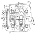
図1は本発明に係る汎用4サイクルエンジンの縦断平面図、図2は図1の2−2線断面図、図3は図1の3−3線断面図、図4は図1のクランク軸周辺部の拡大図、図5は図4の5矢視図、図6は図2の6−6線断面図、図7は図2の7−7線断面図、図8は図6の8−8線断面図、図9は図7の9−9線断面図、図10は図8の10矢視図、図11は従動プーリを取り外した状態で示す、図10との対応図、図12は従動プーリのカム軸への取り付け要領説明図、図13は本発明の別の実施例を示す、図8との対応図である。
1 is a longitudinal plan view of a general-purpose four-cycle engine according to the present invention, FIG. 2 is a sectional view taken along line 2-2 in FIG. 1, FIG. 3 is a sectional view taken along line 3-3 in FIG. FIG. 5 is a sectional view taken along
先ず、図1〜図4において、汎用4サイクルエンジンEのエンジン本体1は、下部に据え付け座2aを持つクランクケース2と、このクランクケース2に一体に連設され、上向き傾斜のシリンダボア3aを有するシリンダブロック3と、このシリンダブロック3の上端面にガスケット4を介して接合されるシリンダヘッド5とを構成要素しており、シリンダヘッド5のシリンダブロック3への接合、即ち締結には、シリンダボア3a周りの4箇所に配置される4本の主連結ボルト6,6…と、後述する2本の補助連結ボルト7,7が使用される。
1 to 4, an engine body 1 of a general-purpose four-cycle engine E includes a crankcase 2 having a
クランクケース2は一側面を開放しており、その開放面からやゝ内方寄りの内周壁には、上記開放側面側を向いて周方向に並ぶ複数の段部8,8…が一体に形成され、これら段部8,8…に軸受ブラケット10が複数のボルト11,11…により固着される。この軸受ブラケット10とクランクケース2の他側壁とで水平姿勢のクランク軸12の両端部がベアリング13,13′を介して支承される。またクランク軸12と平行に隣接配置されるバランサ軸14の両端部が、同じく軸受ブラケット10とクランクケース2の他側壁とでベアリング15,15を介して支承される。
The crankcase 2 is open at one side, and a plurality of
図4及び図5に示すように、クランクケース2の外周面には、前記複数の段部8,8…を囲繞するように連続した補強リブ16が一体に形成され、この補強リブ16の端部は、クランクケース2と一体のシリンダブロック3の外側壁に一体に接続される。
As shown in FIGS. 4 and 5, a continuous reinforcing
而して、上記補強リブ16は、クランクケース2の外周面で、その内側の複数の段部8,8…を相互に連結することになるから、これら段部8,8…により支持される軸受ブラケット10の支持剛性、延いてはこの軸受ブラケット10によるクランク軸12の支持剛性を効果的に強化することができ、その結果、クランクケース2薄肉、軽量化を図ることができる。特に、補強リブ16の端部をシリンダブロック3の外側壁に一体に接続したことにより、補強リブ16の補強機能が高まり、軸受ブラケット10の支持剛性を、より強化することができる。
Thus, the reinforcing
またクランクケース2には、その一側の開放面を閉鎖するサイドカバー17が複数のボルト24,24…により接合される。クランク軸12の一端部は、出力軸部として、このサイドカバー17を貫通して外方に突出し、この出力軸部の外周面に密接するオイルシール18がサイドカバー17に取り付けられる。
Further, a
再び図1において、クランク軸12の他端部は、クランクケース2の他側壁を貫通し、このクランク軸12の他端部に密接するオイルシール19が、前記ベアリング13′の外側に隣接してクランクケース2の他側壁に取り付けられる。クランク軸12の他端部には発電機20のロータを兼るフライホイール21が固着され、このフライホイール21の外側面には冷却ファン22が付設される。さらにクランク軸12の他端部には、クランクケース2に支持されるリコイル式スタータ23が対置される。
In FIG. 1 again, the other end of the
図1及び図3において、クランク軸12には、シリンダボア3aに嵌装されるピストン25がコンロッド26を介して連接される。シリンダヘッド5には、シリンダボア3aに連なる燃焼室27と、この燃焼室27にそれぞれ開口する吸気ポート28i及び排気ポート28eとが形成されると共に、これら吸気及び排気ポート28i,28eの燃焼室27への開口端をそれぞれ開閉する吸気弁ト29i及び排気弁29eが取り付けられる。またこれら吸気及び排気弁29i,29eには、これらを閉じ方向に付勢する弁ばね30i,30eがそれぞれ装着される。そして、これら弁ばね30i,30eと協働する動弁装置35によって吸気及び排気弁29i,29eは開閉駆動される。
1 and 3, a
その動弁装置35について、図3、図4、図6〜図12を参照しながら説明する。
The
先ず図3、図4、図6において、動弁装置35は、クランク軸12と平行にシリンダヘッド5に支承されて吸気カム36i及び排気カム36eを備えるカム軸36と、クランク軸12及びカム軸36間を連結するタイミング伝動装置37と、吸気カム36i及び吸気弁29i間を連動させる吸気ロッカアーム38iと、排気カム36e及び排気弁29e間を連動させる排気ロッカアーム38eとから構成される。
3, 4, and 6, the
カム軸36は、シリンダヘッド5の一側壁5aに形成された袋状の軸受孔39と、シリンダヘッド5中間部の隔壁5bのベアリング装着孔40に嵌装されたボールベアリング41とで両端部を支承される。また吸気及び排気ロッカアーム38i,38eを揺動自在に支承する共通一本のロッカ軸42は、上記一側壁5aと隔壁5bとにそれぞれ形成された第1及び第2支持孔43′,43により両端部が支持される。一側壁5aの第1支持孔43′は袋状、隔壁5bの第2支持43は透孔状になっており、第2支持孔43の外端部に、ロッカ軸42の外端に先端を当接させる固定ボルト44が隔壁5bに螺着される。而して、ロッカ軸42は、袋状第1支持孔43′と固定ボルト44とでスラスト方向の移動を阻止されることになる。
The
上記固定ボルト44は、カム軸36を支承するボールベアリング41のアウタレース41aの外端面に当接する比較的大径のフランジ座44aを頭部に一体に備えている。
The fixing
ところで、ボールベアリング41のインナレース41bは、カム軸36に圧入されるされるものであり、したがって、固定ボルト44のフランジ座44aが上記のようにアウタレース41aの外端に当接すると、カム軸36は、袋状の軸受孔39とフランジ座44aとでスラスト方向の移動を阻止されることになる。
By the way, the
したがって、一本の固定ボルト44により、ロッカ軸42及びカム軸36の両方のスラスト方向の移動を阻止することが可能となり、動弁装置35の部品点数の削減及び構造の簡素化を図り、そのコンパクト化に寄与し、また同装置35の組立性の向上にも寄与し得る。
Therefore, the
上記タイミング伝動装置37は、クランク軸12に固着される歯付きの駆動プーリ45と、カム軸36に固着される歯付きで、その歯数が駆動プーリ45より1/2である従動プーリ46と、これら駆動及び従動プーリ45,46に巻き掛けられる無端のタイミングベルト47とで構成される。而して、クランク軸12の回転は、このタイミング伝動装置37により1/2に減速されてカム軸36に伝達される。そしてカム軸36の回転により、吸気及び排気カム36i,36eが吸気及び排気ロッカアーム38i,38eをそれぞれ弁ばね30i,30eの付勢力に抗して揺動させるので、吸気及び排気弁29i,29eをそれぞれ開閉することができる。
The
このタイミング伝動装置37は、軸受ブラケット10及びサイドカバー17間に画成される下部室48aと、シリンダボア3aの一側でシリンダブロック3に形成される中間室48bと、シリンダヘッド5の一側に形成される上部室48cとを順次連ねてなるタイミング伝動室48に収容される。即ち、駆動プーリ45は下部室48aに配置され、従動プーリ46は上部室48cに配置され、タイミングベルト47は中間室48bを通るように配置される。こうして、軸受ブラケット10及びサイドカバー17間のスペースを、タイミング伝動装置37の設置に有効利用することにより、エンジンEのコンパクト化を図ることができる。
The
一方、シリンダヘッド5には、その一側壁5aと隔壁5bとの間で、上面を開放した動弁室35が形成され、この動弁室35にカム軸36の吸気及び排気カム36i,36e、吸気及び排気ロッカアーム38i,38e等が収容される。この動弁室35の開放上面は、シリンダヘッド5にボルト53で接合されるヘッドカバー52によって閉鎖される。
On the other hand, the
タイミング伝動室48の上部室48cと動弁室35とは、隔壁5bに設けられた通油孔75(図8及び図11参照)と、前記ベアリング装着孔40の内周面に設けられた複数の通油溝76(図6及び図11参照)とを介して相互に連通される。
The
図6〜図9において、シリンダヘッド5の外端面5cには、従動プーリ46の外側面が臨むように上部室48cを開放する作業窓55が設けられ、この作業窓55を通して従動プーリ46のタイミングベルト47内への挿入、並びにカム軸36への従動プーリ46の取り付け作業が行われる。上記外端面5cには、作業窓55を閉鎖する蓋体57がシール部材56を介して複数のボルト58により接合される。
6 to 9, the
図6に明示するように、蓋体57が接合されるシリンダヘッド5の外端面5cは、従動プーリ46の少なくとも駆動プーリ45と反対側の外周の一部が前記作業窓55から露出するように、望ましく従動プーリ46の駆動プーリ45と反対側の半周以上に亙り前記作業窓55から露出するように傾斜した傾斜面5cに形成される。
As shown in FIG. 6, the
こゝで、カム軸36への従動プーリ46の取り付け構造について説明する。
Now, a structure for attaching the driven
図6に示すように、従動プーリ46は、有底円筒状のハブ46aと、このハブ46aから半径方向に広がるウェブ46bと、このウェブ46bの外周に形成された歯付きのリム46cとからなっており、ハブ46aは、上部室48c側に突出したカム軸36の外端部外周に嵌合するようになっている。このハブ46aの端壁には、その中心から偏心した位置を占めるボルト孔60と、このボルト孔60の一側から上記偏心方向と正反対側に延びる位置決め溝61とが設けられる。またリム46cの外側面には第1合印62aが刻設され、この第1合印62aに対応する第2合印62bがシリンダヘッド5の前記外端面5cに刻設される。またウェブ46bには、それを貫通する複数の透孔64,64が設けられる。
As shown in FIG. 6, the driven
一方、カム軸36の外端部には、図6及び図11に示すように、前記ボルト孔60に対応するねじ孔66と、位置決め溝61に対応する位置決めピン67とが設けられる。
On the other hand, as shown in FIGS. 6 and 11, a
而して、クランク軸12がピストン25の特定位置(例えば上死点)に対応した所定回転位置にあり、且つカム軸36が上記クランク軸12に対する所定の位相関係位置にあるとき、上記第1合印62aと第2合印62b、ボルト孔60とねじ孔66、位置決め溝61と位置決めピン67は、両軸12,36の中心を通る直線L上でそれぞれ合致するようになっている。
Thus, when the
そこで、カム軸36に従動プーリ46を取り付けるに当たっては、先ず、クランク軸12を、ピストン25の前記特定位置に対応する回転位置に固定する。次に図12(A)に示すように、リム46cの第1合印62aをシリンダヘッド5の第2合印62bに合わせながら従動プーリ46を、駆動プーリ45に既に掛けたタイミングベルト47内に挿入する。次に、図12(B)に示すように、従動プーリ46のボルト孔60にカム軸36の位置決めピン67を受け入れ、そしてこの位置決めピン67を位置決め溝61に誘導するように従動プーリ46をタイミングベルト47と共に動かすと、それに応じてカム軸36が回転し、位置決めピン67が位置決め溝61の先端部まで来ると、図12(C)に示すように、カム軸36とハブ46aとが同軸上に並ぶ同時に、ボルト孔60とねじ孔66とが相互に合致することになる。
Therefore, when attaching the driven
このようにボルト孔60に受け入れた位置決めピン67を位置決め溝61に誘導するという極めて簡単な操作により、クランク軸12及びカム軸36の中心を通る直線L上に第1及び第2合印62a,62b、ボルト孔60及びねじ孔66、並びに位置決め溝61及び位置決めピン67が一斉に配列されることになる。そしてこの状態を目視することにより、クランク軸12及びカム軸36が所定の位相関係にあることを容易に確認することができる。
As described above, the
そこで、図6に示すように、取り付けボルト68をボルト孔60に通してねじ孔66に螺合、緊締することにより、ハブ46aをカム軸36に固定する。こうして、予めクランクケース2及びシリンダヘッド5に装着されるクランク軸12及びカム軸36に、それらの所定の位相関係において、タイミング伝動装置37が取り付けられる。
Therefore, as shown in FIG. 6, the
この場合、ボルト孔60及びねじ孔66を、前記ハブ46a及びカム軸36のそれぞれの中心から偏心した位置に配置されているから、偏心した一本の取り付けボルト68を介して従動プーリ46の回転をカム軸36に確実に伝達することができると共に、この取り付けボルト68の緩みを防ぐことができる。
In this case, since the
また前記ねじ孔66及び位置決めピン67は、カム軸36の中心から互いに反対方向に偏心した位置に配置されるので、従動プーリ46のハブ46aの狭い端壁に形成されるボルト孔60及び位置決め溝61に、それぞれ充分な偏心量を与えることができ、これにより位置決め溝61の位置決めピンに対する位置決め効果と、取り付けボルト68のトルク容量を高めることができる。
Further, since the
ところで、前述のように、作業窓55が開口するシリンダヘッド5の外端面が傾斜面5cとなっていて、従動プーリ46の外周の一部が作業窓55から露出するようになっているので、作業窓55外に露出した従動プーリ46の一部を、シリンダヘッド5に邪魔されることなく、工具等で容易に把持することができ、これにより従動プーリ46のカム軸36への取り付け作業を容易に行うことができ、またその取り外しも容易となる。したがって組立性及びメンテナンス性の向上に寄与し得る。
By the way, as described above, the outer end surface of the
シリンダヘッド5の外端面5c、即ち傾斜面5cに接合される蓋体57の側壁73は、上記傾斜面5cに沿って傾斜するように形成される。こうすることで、エンジン本体1の頭部は、その横幅が先端側に向かって狭まる形状となり、エンジンEのコンパクト化を図ることができる。
The
図7〜及び図9に示すように、シリンダヘッド5には、作業窓55の下方で作業窓55の外方に張り出す一対の張り出し部70,70が形成されており、これら張り出し部70,70は、前記ガスケット4を介してシリンダブロック3の、前記中間室48b外側の上端面に重ねられ、補助連結ボルト7,7によりシリンダブロック3に締結される。
As shown in FIGS. 7 to 9, the
このような補助連結ボルト7,7の締結によれば、タイミングベルト47を収容する中間室48bの外側においても、シリンダブロック3及びシリンダヘッド5のガスケット4に対する面圧を充分に高めることができる。しかも補助連結ボルト7,7の上方には、前記傾斜面5cの存在により、補助連結ボルト7,7を操作する工具の受容スペースが充分に確保されるため、補助連結ボルト7,7の締めつけ作業を容易に行うことができる。またこうしたことは、前記張り出し部70,70の作業窓55外方への張り出し量を少なくし得ることを意味し、これもエンジンEのコンパクト化に寄与することになる。
By fastening the
尚、補助連結ボルト7,7の操作は、蓋体57の取り付け前に行うものである。
The operation of the auxiliary connecting
次に、上記動弁装置35の潤滑について説明する。
Next, lubrication of the
図1〜図3、図6及び図8において、前記タイミング伝動室48の下部室48aは、前記軸受ブラケット10を支持する、クランクケース2内壁の複数の段部8,8…間を通してクランクケース2内部、即ちクランク室9と連通しており、これらクランク室9及び下部室48aには共通の潤滑オイル71が一定量貯留される。
1 to 3, 6, and 8, the
図3に示すように、下部室48aには、クランク軸12からギヤ74,74′を介して駆動される羽根車型のオイルスリンガ72が、その1部を下部室48aの貯留オイル71に浸漬させるようにして配設される。このオイルスリンガ72は、その回転によりオイル71を周囲に飛散させるものであって、その飛散オイルをタイミングベルト47側へ誘導するためのオイル誘導壁73が、オイルスリンガ72及び、駆動プーリ45側のタイミングベルト47の周囲を囲むようにして軸受ブラケット10の外側面に一体に形成される。軸受ブラケット10は比較的小部品であるから、これをオイル誘導壁73と共に容易に鋳造することができる。しかも、軸受ブラケット10は、このオイル誘導壁73を一体に有することにより、その剛性が強化され、クランク軸12の支持剛性を高める上でも有効となる。
As shown in FIG. 3, in the
而して、下部室48aでは、オイルスリンガ72からの飛散オイルがオイル誘導壁73によりタイミングベルト47側へ誘導され、そのタイミングベルト47に付着したオイルは、該ベルト47により上部室48cへと移送され、タイミングベルト47が従動プーリ46に巻きつくとき、遠心力により振り切られて周囲に飛散し、周囲の壁に衝突してオイルミストを生成し、このオイルミストが上部室48cを満たすことになるので、それによってタイミング伝動装置37全体のみならず、カム軸36のボールベアリング41を潤滑することができる。
Thus, in the
特に、上部室48cでは、タイミングベルト47から振り切られオイルの一部が、蓋体57の傾斜した内面に衝突すると、従動プーリ46のウェブ46b側に跳ね返る。そしてこのオイルは従動プーリ46の透孔64,64を通過して、上記ボールベアリング41に振りかかるので、これによっても上記ボールベアリング41を潤滑する。また上記ボールベアリング41に振りかかったオイルの一部は、該ベアリング41外周の通油溝76を通って動弁室35に移り、動弁室35側からも上記ボールベアリング41を潤滑することになる。したがってボールベアリング41の潤滑は極めて良好に行われる。
In particular, in the
図2に示すように、動弁室35の底部は、シリンダボア3aの一側に沿うようにシリンダヘッド5及びシリンダブロック3に形成された一連のオイル戻し通路77を介してクランク室9に連通される。そのオイル戻し通路77は、動弁室35からクランク室9にオイルが流下するよう、クランク室9に向かって下っている。
As shown in FIG. 2, the bottom of the
ところで、エンジンEの運転中、クランク室では、ピストン25の昇降に伴なう圧力の脈動が生じ、その脈動圧力がオイル戻し通路77、通油孔75及び通油溝76を通して動弁室49及びタイミング伝動室48に伝達するとき、動弁室49及びタイミング伝動室48間でオイルミストの行き来が起こるので、動弁装置35全体を効果的に潤滑することができる。
By the way, during the operation of the engine E, in the crank chamber, a pulsation of pressure accompanying the raising and lowering of the
そして潤滑後、動弁室35に溜まったオイルは、オイル戻し通路77を流下してクランク室9に戻る。またタイミング伝動室48の底面も下部室48aに向かって下っているので、上部室48cに溜まったオイルは、中間室48bを流下して下部室48aに戻る。
After lubrication, the oil accumulated in the
このようにオイルスリンガ72及びタイミング伝動装置37の作動、並びにクランク室9の脈動圧力を利用して、互いに仕切られるタイミング伝動室48及び動弁室49内をオイルミストにより潤滑することができるので、潤滑専用のオイルポンプが不要となり、エンジンEの構造の簡素化及びコンパクト化、並びにコストの低減に資することができる。しかもカム軸36は、吸気及び排気弁29i,29eに対する頭上配置を維持し得るので、エンジンの所望の出力性能を確保することができる。
In this way, the operation of the
次に、図13に示す本発明の別の実施例について説明する。 Next, another embodiment of the present invention shown in FIG. 13 will be described.
この実施例は、タイミング伝動室48及び動弁室49間を連通する通油孔76に、動弁室49からタイミング伝動室48への負圧の伝達のみを許容する一方向弁79が設けられる。その他の構成は前実施例と同様であるから、図13中、前実施例と対応する部分には、同一の参照符号を付して、その説明を省略する。
In this embodiment, a one-
この実施例においては、クランク室9で発生した脈動圧力が動弁室49に伝達すると、そのうちの負圧のみが一方向弁79を通過してタイミング伝動室48に作用することになるから、その負圧の作用によりタイミング伝動室48のオイルミストを動弁室49へ効率良く引き込むことができ、動弁室49内の潤滑性を高めることができる。
In this embodiment, when the pulsation pressure generated in the
尚、本発明は前記実施例に限定されるものではなく、その要旨を逸脱しない範囲で種々の設計変更が可能である。例えば、ベルト式のタイミング伝動装置37をチェーン式のものに置き換えることもできる。
In addition, this invention is not limited to the said Example, A various design change is possible in the range which does not deviate from the summary. For example, the belt type timing
E・・・・・エンジン
2・・・・・クランクケース
3・・・・・シリンダブロック
5・・・・・シリンダヘッド
9・・・・・クランク室
12・・・・クランク軸
29i・・・吸気弁
29e・・・排気弁
35・・・・動弁装置
36・・・・カム軸
37・・・・タイミング伝動装置
41・・・・軸受(ボールベアリング)
46・・・・従動回転部材(従動プーリ)
47・・・・無端伝動部材(タイミングベルト)
48・・・・タイミング伝動室
49・・・・動弁室
55・・・・作業窓
57・・・・蓋体
64・・・・透孔
71・・・・オイル
72・・・・オイルスリンガ
75・・・・通油孔
76・・・・通油溝
77・・・・オイル戻し孔
79・・・・一方向弁
E ... Engine 2 ...
46... Driven rotation member (driven pulley)
47... Endless transmission member (timing belt)
48 ... Timing
Claims (3)
タイミング伝動室(48)には、その底部に貯留する潤滑オイル(71)を飛散させてタイミング伝動装置(37)の下部に付着させるオイルスリンガ(72)を配設し、前記隔壁(5b)には、タイミング伝動装置(37)の上部で振り切られた飛散オイルを動弁室(49)に誘導する通油孔(75)を設け、クランクケース(2)内のクランク室(9)で発生する脈動圧力を動弁室(49)に伝達すると共に動弁室(49)に溜まったオイルをクランク室(9)に流下させるオイル戻し通路(77)をシリンダヘッド(5)及びシリンダブロック(3)に設け、シリンダヘッド(5)の他側面には、タイミング伝動装置(37)の従動回転部材(46)のカム軸(36)への着脱を可能にする作業窓(55)を開口させ、この作業窓(55)を閉鎖する蓋体(57)の側壁を従動回転部材(46)の側面に対して傾斜させて、タイミング伝動装置(37)の上部で振り切られた飛散オイルが蓋体(57)の側壁内面で従動回転部材(46)側に反射するようにし、その反射オイルの通過を許容する透孔(64)を従動回転部材(46)に設けたことを特徴とする、エンジンの動弁装置。 A crankshaft (supported by the crankcase (2) is supported by a timing transmission chamber (48) formed on one side of the engine body (1) comprising the crankcase (2), the cylinder block (3) and the cylinder head (5). 12) and a timing transmission device (37) for connecting the cylinder head (5) to the camshaft (36) supported on the heads of the intake and exhaust valves (29i, 29e). ) And the partition wall (5b) formed on the cylinder head (5) and adjacent to the timing transmission chamber (48), both ends of the camshaft (36) are supported, and the camshaft ( 36) In a valve operating apparatus for an engine, a valve operating chamber (49) for accommodating 36) is defined between the one side wall (5a) and the partition wall (5b).
The timing transmission chamber (48) is provided with an oil slinger (72) that scatters lubricating oil (71) stored in the bottom of the timing transmission chamber (48) and adheres to the lower part of the timing transmission device (37). Is provided in the crank chamber (9) in the crankcase (2) by providing an oil passage hole (75) for guiding the scattered oil swung off at the top of the timing transmission (37) to the valve chamber (49). An oil return passage (77) that transmits pulsation pressure to the valve chamber (49) and causes oil accumulated in the valve chamber (49) to flow down to the crank chamber (9) is provided in the cylinder head (5) and the cylinder block (3). A working window (55) that allows the driven rotation member (46) of the timing transmission (37) to be attached to and detached from the cam shaft (36) is opened on the other side of the cylinder head (5). Working window (5 The side wall of the lid (57) is inclined with respect to the side surface of the driven rotation member (46), and the scattered oil sprinkled off at the top of the timing transmission (37) is the inner surface of the side wall of the lid (57). in the to reflect the driven rotary member (46) side, a hole (64) allowing the passage of the reflected oil, characterized in that provided on the driven rotary member (46), the valve operating equipment of the engine.
前記隔壁(5b)に、カム軸(36)の軸受41の周囲でタイミング伝動室(48)及び動弁室(49)間を連通する通油溝(76)を設けたことを特徴とする、エンジンの動弁装置。 The valve gear for an engine according to claim 1 ,
The partition wall (5b) is provided with an oil passage groove (76) communicating between the timing transmission chamber (48) and the valve operating chamber (49) around the bearing 41 of the camshaft (36). Engine valve gear.
前記通油孔(76)に、動弁室(49)からタイミング伝動室(48)への負圧の伝達のみを許容する一方向弁(79)を設けたことを特徴とする、エンジンの動弁装置。 The valve gear for an engine according to claim 1 or 2 ,
The oil passage hole (76) is provided with a one-way valve (79) that allows only negative pressure to be transmitted from the valve chamber (49) to the timing transmission chamber (48). Valve device.
Priority Applications (15)
| Application Number | Priority Date | Filing Date | Title |
|---|---|---|---|
| JP2005183604A JP4511999B2 (en) | 2005-06-23 | 2005-06-23 | Engine valve gear |
| TW095117448A TWI314178B (en) | 2005-06-23 | 2006-05-17 | Engine valve operating system |
| MYPI20062838A MY144093A (en) | 2005-06-23 | 2006-06-15 | Engine valve operating system |
| AU2006260301A AU2006260301B2 (en) | 2005-06-23 | 2006-06-20 | Engine valve operating system |
| PCT/JP2006/312285 WO2006137378A1 (en) | 2005-06-23 | 2006-06-20 | Valve gear of engine |
| CA2608275A CA2608275C (en) | 2005-06-23 | 2006-06-20 | Engine valve operating system |
| EP06766946A EP1895117B1 (en) | 2005-06-23 | 2006-06-20 | Valve gear of engine |
| ES06766946T ES2377450T3 (en) | 2005-06-23 | 2006-06-20 | Engine valve gear |
| US11/921,078 US7971563B2 (en) | 2005-06-23 | 2006-06-20 | Engine valve operating system |
| CN2006800222814A CN101203662B (en) | 2005-06-23 | 2006-06-20 | Valve gear of engine |
| BRPI0612508-5A BRPI0612508A2 (en) | 2005-06-23 | 2006-06-20 | engine valve operation system |
| KR1020077028117A KR100946746B1 (en) | 2005-06-23 | 2006-06-20 | Valve gear of engine |
| PE2006000696A PE20070130A1 (en) | 2005-06-23 | 2006-06-21 | ENGINE VALVE OPERATING SYSTEM |
| ARP060102675A AR054493A1 (en) | 2005-06-23 | 2006-06-22 | OPERATING SYSTEM OF MOTOR VALVE |
| PA20068682601A PA8682601A1 (en) | 2005-06-23 | 2006-06-23 | OPERATING SYSTEM OF MOTOR VALVE |
Applications Claiming Priority (1)
| Application Number | Priority Date | Filing Date | Title |
|---|---|---|---|
| JP2005183604A JP4511999B2 (en) | 2005-06-23 | 2005-06-23 | Engine valve gear |
Publications (2)
| Publication Number | Publication Date |
|---|---|
| JP2007002747A JP2007002747A (en) | 2007-01-11 |
| JP4511999B2 true JP4511999B2 (en) | 2010-07-28 |
Family
ID=37570407
Family Applications (1)
| Application Number | Title | Priority Date | Filing Date |
|---|---|---|---|
| JP2005183604A Expired - Fee Related JP4511999B2 (en) | 2005-06-23 | 2005-06-23 | Engine valve gear |
Country Status (15)
| Country | Link |
|---|---|
| US (1) | US7971563B2 (en) |
| EP (1) | EP1895117B1 (en) |
| JP (1) | JP4511999B2 (en) |
| KR (1) | KR100946746B1 (en) |
| CN (1) | CN101203662B (en) |
| AR (1) | AR054493A1 (en) |
| AU (1) | AU2006260301B2 (en) |
| BR (1) | BRPI0612508A2 (en) |
| CA (1) | CA2608275C (en) |
| ES (1) | ES2377450T3 (en) |
| MY (1) | MY144093A (en) |
| PA (1) | PA8682601A1 (en) |
| PE (1) | PE20070130A1 (en) |
| TW (1) | TWI314178B (en) |
| WO (1) | WO2006137378A1 (en) |
Families Citing this family (10)
| Publication number | Priority date | Publication date | Assignee | Title |
|---|---|---|---|---|
| JP4247644B2 (en) | 2007-06-29 | 2009-04-02 | 三菱自動車工業株式会社 | Variable valve operating device for internal combustion engine |
| CN101818671B (en) * | 2010-03-18 | 2012-02-22 | 厦门理工学院 | diesel engine valve lubricating device |
| SE538122C2 (en) * | 2010-05-11 | 2016-03-08 | Agap Hb | Camshaft with removable bearing position |
| JP5536578B2 (en) * | 2010-07-22 | 2014-07-02 | 株式会社マキタ | 4-cycle engine lubrication system |
| CN102303718B (en) * | 2011-05-23 | 2013-01-16 | 赵国平 | Progressive adding and proportioning mechanism for granular medicaments |
| DE102011080267A1 (en) * | 2011-08-02 | 2013-02-07 | Schaeffler Technologies AG & Co. KG | Verschiebenutkontur of sliding cam units of a reciprocating internal combustion engine |
| KR101167505B1 (en) * | 2011-11-01 | 2012-07-23 | 주식회사 유니크 | Oil pump control valve |
| JP6458628B2 (en) * | 2015-05-11 | 2019-01-30 | スズキ株式会社 | Valve lubrication device for internal combustion engine |
| CN105697185B (en) * | 2016-01-28 | 2018-11-16 | 隆鑫通用动力股份有限公司 | crankcase |
| JP6843172B2 (en) * | 2019-03-29 | 2021-03-17 | 本田技研工業株式会社 | Internal combustion engine |
Citations (2)
| Publication number | Priority date | Publication date | Assignee | Title |
|---|---|---|---|---|
| JPH07305615A (en) * | 1994-05-11 | 1995-11-21 | Kawasaki Heavy Ind Ltd | Four cycle engine |
| JP2002147213A (en) * | 2000-11-10 | 2002-05-22 | Honda Motor Co Ltd | Lubricating device for four-cycle engine |
Family Cites Families (10)
| Publication number | Priority date | Publication date | Assignee | Title |
|---|---|---|---|---|
| JPS61182406A (en) | 1985-02-08 | 1986-08-15 | Honda Motor Co Ltd | Lubricator for 4-cycle engine |
| JPH0113919Y2 (en) * | 1985-02-22 | 1989-04-24 | ||
| JPS6413919A (en) | 1987-07-08 | 1989-01-18 | Hitachi Lighting Ltd | Vegetable factory system |
| JPH01316238A (en) | 1988-06-15 | 1989-12-21 | Daikyo Inc | Manufacturing method of timing gear cover |
| JPH0341103U (en) | 1989-08-28 | 1991-04-19 | ||
| JP2001059409A (en) | 1999-08-23 | 2001-03-06 | Daihatsu Motor Co Ltd | Lubricating device for camshaft seal part in internal combustion engine |
| US6508224B2 (en) * | 2000-03-14 | 2003-01-21 | Honda Giken Kogyo Kabushiki Kaisha | Handheld type four-cycle engine |
| JP3784607B2 (en) * | 2000-03-21 | 2006-06-14 | 本田技研工業株式会社 | Oil mist generator for handheld four-cycle engine |
| JP3784608B2 (en) * | 2000-03-21 | 2006-06-14 | 本田技研工業株式会社 | Handheld four-cycle engine |
| JP2002138898A (en) * | 2000-11-01 | 2002-05-17 | Honda Motor Co Ltd | Valve mechanism for engine |
-
2005
- 2005-06-23 JP JP2005183604A patent/JP4511999B2/en not_active Expired - Fee Related
-
2006
- 2006-05-17 TW TW095117448A patent/TWI314178B/en not_active IP Right Cessation
- 2006-06-15 MY MYPI20062838A patent/MY144093A/en unknown
- 2006-06-20 KR KR1020077028117A patent/KR100946746B1/en not_active IP Right Cessation
- 2006-06-20 EP EP06766946A patent/EP1895117B1/en active Active
- 2006-06-20 CN CN2006800222814A patent/CN101203662B/en not_active Expired - Fee Related
- 2006-06-20 BR BRPI0612508-5A patent/BRPI0612508A2/en not_active IP Right Cessation
- 2006-06-20 US US11/921,078 patent/US7971563B2/en active Active
- 2006-06-20 AU AU2006260301A patent/AU2006260301B2/en not_active Ceased
- 2006-06-20 CA CA2608275A patent/CA2608275C/en not_active Expired - Fee Related
- 2006-06-20 ES ES06766946T patent/ES2377450T3/en active Active
- 2006-06-20 WO PCT/JP2006/312285 patent/WO2006137378A1/en active Application Filing
- 2006-06-21 PE PE2006000696A patent/PE20070130A1/en not_active Application Discontinuation
- 2006-06-22 AR ARP060102675A patent/AR054493A1/en active IP Right Grant
- 2006-06-23 PA PA20068682601A patent/PA8682601A1/en unknown
Patent Citations (2)
| Publication number | Priority date | Publication date | Assignee | Title |
|---|---|---|---|---|
| JPH07305615A (en) * | 1994-05-11 | 1995-11-21 | Kawasaki Heavy Ind Ltd | Four cycle engine |
| JP2002147213A (en) * | 2000-11-10 | 2002-05-22 | Honda Motor Co Ltd | Lubricating device for four-cycle engine |
Also Published As
| Publication number | Publication date |
|---|---|
| EP1895117A4 (en) | 2010-11-24 |
| CA2608275C (en) | 2012-01-24 |
| MY144093A (en) | 2011-08-15 |
| CA2608275A1 (en) | 2006-12-28 |
| EP1895117A1 (en) | 2008-03-05 |
| TW200704871A (en) | 2007-02-01 |
| KR20080008392A (en) | 2008-01-23 |
| AU2006260301A1 (en) | 2006-12-28 |
| BRPI0612508A2 (en) | 2010-11-23 |
| AR054493A1 (en) | 2007-06-27 |
| AU2006260301B2 (en) | 2010-04-29 |
| JP2007002747A (en) | 2007-01-11 |
| CN101203662A (en) | 2008-06-18 |
| US20100064995A1 (en) | 2010-03-18 |
| CN101203662B (en) | 2010-05-19 |
| KR100946746B1 (en) | 2010-03-11 |
| ES2377450T3 (en) | 2012-03-27 |
| EP1895117B1 (en) | 2012-01-11 |
| PA8682601A1 (en) | 2007-01-17 |
| WO2006137378A1 (en) | 2006-12-28 |
| PE20070130A1 (en) | 2007-02-09 |
| US7971563B2 (en) | 2011-07-05 |
| TWI314178B (en) | 2009-09-01 |
Similar Documents
| Publication | Publication Date | Title |
|---|---|---|
| JP4511999B2 (en) | Engine valve gear | |
| WO2006137520A1 (en) | Gas-liquid separation device for engine | |
| JP4382010B2 (en) | Engine valve gear | |
| JP4283251B2 (en) | engine | |
| JP2007002739A (en) | Engine | |
| KR100947005B1 (en) | Engine | |
| JP4319170B2 (en) | Engine valve gear | |
| JP2000027948A (en) | Balancer device of outboard motor | |
| JPS62284913A (en) | Lubrication structure for cam sprocket for internal combustion engine |
Legal Events
| Date | Code | Title | Description |
|---|---|---|---|
| A621 | Written request for application examination |
Free format text: JAPANESE INTERMEDIATE CODE: A621 Effective date: 20071126 |
|
| A131 | Notification of reasons for refusal |
Free format text: JAPANESE INTERMEDIATE CODE: A131 Effective date: 20100303 |
|
| A521 | Request for written amendment filed |
Free format text: JAPANESE INTERMEDIATE CODE: A523 Effective date: 20100329 |
|
| TRDD | Decision of grant or rejection written | ||
| A01 | Written decision to grant a patent or to grant a registration (utility model) |
Free format text: JAPANESE INTERMEDIATE CODE: A01 Effective date: 20100428 |
|
| A01 | Written decision to grant a patent or to grant a registration (utility model) |
Free format text: JAPANESE INTERMEDIATE CODE: A01 |
|
| A61 | First payment of annual fees (during grant procedure) |
Free format text: JAPANESE INTERMEDIATE CODE: A61 Effective date: 20100507 |
|
| FPAY | Renewal fee payment (event date is renewal date of database) |
Free format text: PAYMENT UNTIL: 20130514 Year of fee payment: 3 |
|
| R150 | Certificate of patent or registration of utility model |
Ref document number: 4511999 Country of ref document: JP Free format text: JAPANESE INTERMEDIATE CODE: R150 Free format text: JAPANESE INTERMEDIATE CODE: R150 |
|
| FPAY | Renewal fee payment (event date is renewal date of database) |
Free format text: PAYMENT UNTIL: 20130514 Year of fee payment: 3 |
|
| FPAY | Renewal fee payment (event date is renewal date of database) |
Free format text: PAYMENT UNTIL: 20140514 Year of fee payment: 4 |
|
| LAPS | Cancellation because of no payment of annual fees |