EP1136285A2 - Wheel bearing arrangement for a dual wheel assembly - Google Patents
Wheel bearing arrangement for a dual wheel assembly Download PDFInfo
- Publication number
- EP1136285A2 EP1136285A2 EP01302568A EP01302568A EP1136285A2 EP 1136285 A2 EP1136285 A2 EP 1136285A2 EP 01302568 A EP01302568 A EP 01302568A EP 01302568 A EP01302568 A EP 01302568A EP 1136285 A2 EP1136285 A2 EP 1136285A2
- Authority
- EP
- European Patent Office
- Prior art keywords
- wheel
- assembly
- wheel hub
- shoulder
- axle
- Prior art date
- Legal status (The legal status is an assumption and is not a legal conclusion. Google has not performed a legal analysis and makes no representation as to the accuracy of the status listed.)
- Withdrawn
Links
Images
Classifications
-
- B—PERFORMING OPERATIONS; TRANSPORTING
- B60—VEHICLES IN GENERAL
- B60B—VEHICLE WHEELS; CASTORS; AXLES FOR WHEELS OR CASTORS; INCREASING WHEEL ADHESION
- B60B11/00—Units comprising multiple wheels arranged side by side; Wheels having more than one rim or capable of carrying more than one tyre
-
- B—PERFORMING OPERATIONS; TRANSPORTING
- B60—VEHICLES IN GENERAL
- B60B—VEHICLE WHEELS; CASTORS; AXLES FOR WHEELS OR CASTORS; INCREASING WHEEL ADHESION
- B60B11/00—Units comprising multiple wheels arranged side by side; Wheels having more than one rim or capable of carrying more than one tyre
- B60B11/06—Wheels with more than one rim mounted on a single wheel body
Definitions
- This invention relates to an axle assembly having multiple wheels at each end of an axle housing, and more specifically, the invention relates to a bearing arrangement for dual wheel assemblies in which one wheel is permitted to rotate relative to the other wheel.
- Axle assemblies having dual wheels on either end of the axle have been used to increase the load bearing capability of heavy duty vehicles.
- the pair of wheels on each end of the axle assembly are secured together so that they rotate together about an axis.
- Some heavy duty vehicles, such as lift trucks, undergo numerous turning maneuvers which wear the tires significantly. The tire wear is caused when the tires scrub, or drag, since the wheels that are secured together must travel different distances at the inside and outside of the turning radius. Tire wear and maintenance on heavy duty lift trucks due to scrub cost thousands of dollars annually per vehicle.
- Dual wheel assembly designs have been proposed that permit the wheels to rotate relative to one another. Many designs have been developed which utilize a gear set between the wheels. As a result, very complex wheel bearing arrangements have been used which makes installation and removal of the wheels difficult. If only the outer wheel needs to be removed for repair, for example, both wheels and their associated bearing assemblies may need to be removed. That is, the wheel bearing arrangement for one wheel is not independent from the wheel bearing arrangement for the other wheel. Therefore, what is needed is a wheel bearing arrangement for a dual wheel assembly that is more modular which allows easy installation and removal of each wheel.
- the present invention provides a dual wheel assembly for a vehicle that includes an axle assembly having an axle shaft disposed therein which defines an axis.
- the axle assembly has an inboard portion and an outboard portion adjacent to the inboard portion proximate to a terminal end of the axle assembly.
- First and second wheel hubs are supported on the outboard and the inboard portions, respectively.
- the first wheel hub is coupled to the axle shaft so that the first wheel hub may be driven about the axis.
- the second wheel hub is rotatable about the axis relative to the first wheel hub. In this manner, tire scrub is reduced since the wheel hubs may rotate at different speeds, and different directions if necessary.
- a first bearing assembly is interposed between the first wheel hub and the outboard portion for supporting the first wheel hub on the outboard portion.
- the outboard portion has a first shoulder with the first bearing assembly abutting the first shoulder.
- a second bearing assembly is interposed between the second wheel hub and the inboard portion for supporting the second wheel hub on the inboard portion, and the inboard portion has a second shoulder with the second bearing assembly abutting the second shoulder.
- First and second securing members are attached to the axle assembly and are adjacent to the first and the second bearing assemblies, respectively, opposite the first and the second shoulders, respectively. The first and second securing members retain the bearing assemblies against the shoulders and retain the first and the second wheel hubs on the outboard and the inboard portions, respectively. In this manner, the wheel hubs may be more easily installed and removed as units.
- the above invention provides a wheel bearing arrangement for a dual wheel assembly that is more modular which allows easy installation and removal of each wheel.
- a dual wheel assembly 10 for a vehicle is shown in Figure 1.
- the dual wheel assembly 10 includes an axle assembly 12 having an axle shaft 14 disposed therein, which defines a rotational axis A.
- the axle assembly 12 has an inboard portion 20 and an outboard portion 22 adjacent to the inboard portion 20 and proximate to a terminal end 24 of the axle assembly 12.
- the axle assembly 12 includes an axle housing 26 that defines the inboard portion 20.
- the outboard portion 22 may be defined by the axle housing 26 or by an support member, which is discussed in more detail below.
- the inboard portion 20 has inboard diameter that is larger than the diameter of the terminal end 24, which facilitates ease of assembly which will be appreciated from the discussion below.
- First 30 and second 32 wheel hubs are supported on the outboard 22 and the inboard 20 portions, respectively.
- the first wheel hub 30 is coupled to the axle shaft 14 for being driven by a drive mechanism about the axis A.
- the second wheel hub 32 is rotatable about the axis A relative to the first wheel hub 30, preferably without a mechanical coupling, such as a gear set, between them. That is, the second wheel 32 is undriven and free to rotate independently of the first hub 30.
- the dual wheel assembly 10 further includes a planetary gear set 36 mechanically interconnecting the axle shaft 14 and the first wheel hub 30, in a manner known in the art, for providing torque multiplication to the first wheel hub 30.
- the planetary gear set 36 includes a removable ring gear support 38 splined to a portion 40 of the axle housing 36 to prevent rotation about the axis A.
- a brass bushing 41 is arranged between the terminal end 24 and the ring gear support 38.
- An outer cylindrical surface of the ring gear support 38 forms the outboard portion 22. If a planetary gear set 36 is not used, the portion 40 of the axle housing 26 may form the outboard portion 22.
- a ring gear 42 is arranged on the ring gear support 38, and a sun gear 44 is splined to the axle shaft 14.
- Planetary gears 46 are supported by a cover 48 and are arranged between the sun gear 44 and the ring gear 44. In this manner, the axle shaft 14 drives the first hub 30 through the planetary gear set 36 to achieve a multiplication of torque at the first hub 30.
- a first bearing assembly 50 is interposed between the first wheel hub 30 and the outboard portion 22 for rotationally supporting the first wheel hub 30 thereon.
- the outboard portion 22 has a first shoulder 52 that the first bearing assembly 50 abuts to axially locate the first bearing assembly 50.
- a first securing member 54 preferably a nut, is secured to the ring gear support 38 adjacent to the first bearing assembly 50 and opposite the first shoulder 52 to securely retain the first bearing assembly 50 in an axial position.
- Another nut 56 fastened to the terminal end 24 secures the ring gear support 38 and first wheel hub 30 to the axle housing 26.
- a keeper 58 coacts with the nut 56 to prevent the nut 56 from loosening from the terminal end 24.
- the first bearing assembly 50 may be interposed between the portion 40 and the first wheel hub 30 so that the first wheel hub 30 is supported directly on the axle housing 26.
- the diameter of the portion 40 is smaller than the diameter of the inboard portion 20 so that the second wheel hub 32 may be easily installed and removed, as discussed below.
- a second bearing assembly 60 is interposed between the second wheel hub 32 and the inboard portion 20 for rotationally supporting the second wheel hub 32 thereon.
- the inboard portion 20 has a second shoulder 62 with the second bearing assembly 60 abutting the second shoulder 62 to axially locate the second bearing assembly 60.
- a second securing member 64 preferably a nut, is secured to the inboard portion 20 adjacent to the second bearing assembly 60 and opposite the second shoulder 62 to securely retain the second bearing assembly 50 in an axial position along the axle housing 26.
- the wheel bearing assembly for the innermost wheel is secured independently of the outermost wheel. That is, the preload of the outer bearing assembly does not affect the inner bearing assembly. In this manner, the first wheel hub 30 may be installed and removed as a unit without affecting the second wheel hub 32.
- Seals 66, 67 are arranged between the first 30 and second 32 wheel hubs and the second wheel hub 32 and axle housing 26, respectively, to seal the bearing area and prevent contaminants from penetrating the bearing assemblies 50, 60.
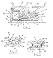
- first 50 and second 60 bearing assemblies are shown in Figures 2 and 3, although bearing assemblies other than the type shown may be used.
- a suitable ball bearing assembly may be used.
- the first 30 and second 32 wheel hubs each include a third shoulder 68 with each of the bearing assemblies 50, 60 abutting the respective third shoulder 68 to axially locate the bearing assemblies 50, 60 relative to the wheel hubs 30, 32.
- the bearing assemblies 50, 60 typically must be axially located wheel hubs 30, 32 in addition to axially locating the bearing assemblies 50, 60 relative to the outboard 22 and inboard 20 portions to ensure that the wheel hubs 30, 32 do not shift relative to the axle housing 26.
- the first 50 and second 60 bearing assemblies each comprise a pair of spaced apart roller bearing assemblies 70, as well known in the art, with the third shoulder 68 interposed between the roller bearing assemblies 70. In this manner, the outer races 71 of the bearing assemblies 70 abut the third shoulder to axially locate the bearing assemblies 70 relative to the second wheel hub.
- the first 50 and second 60 bearing assemblies each comprise a unitized bearing assembly 72 with the outer race 74 abutting the third shoulder 68 and the inner race 76 abutting the second shoulder 62 and the nut 64.
- a retainer 78 is used to abut each of the unitized bearing assemblies 72 opposite the respective third shoulder 68 for locating the bearing assemblies 72 relative to its respective wheel hub.
Abstract
Description
- This invention relates to an axle assembly having multiple wheels at each end of an axle housing, and more specifically, the invention relates to a bearing arrangement for dual wheel assemblies in which one wheel is permitted to rotate relative to the other wheel.
- Axle assemblies having dual wheels on either end of the axle have been used to increase the load bearing capability of heavy duty vehicles. Typically the pair of wheels on each end of the axle assembly are secured together so that they rotate together about an axis. Some heavy duty vehicles, such as lift trucks, undergo numerous turning maneuvers which wear the tires significantly. The tire wear is caused when the tires scrub, or drag, since the wheels that are secured together must travel different distances at the inside and outside of the turning radius. Tire wear and maintenance on heavy duty lift trucks due to scrub cost thousands of dollars annually per vehicle.
- Dual wheel assembly designs have been proposed that permit the wheels to rotate relative to one another. Many designs have been developed which utilize a gear set between the wheels. As a result, very complex wheel bearing arrangements have been used which makes installation and removal of the wheels difficult. If only the outer wheel needs to be removed for repair, for example, both wheels and their associated bearing assemblies may need to be removed. That is, the wheel bearing arrangement for one wheel is not independent from the wheel bearing arrangement for the other wheel. Therefore, what is needed is a wheel bearing arrangement for a dual wheel assembly that is more modular which allows easy installation and removal of each wheel.
- The present invention provides a dual wheel assembly for a vehicle that includes an axle assembly having an axle shaft disposed therein which defines an axis. The axle assembly has an inboard portion and an outboard portion adjacent to the inboard portion proximate to a terminal end of the axle assembly. First and second wheel hubs are supported on the outboard and the inboard portions, respectively. The first wheel hub is coupled to the axle shaft so that the first wheel hub may be driven about the axis. The second wheel hub is rotatable about the axis relative to the first wheel hub. In this manner, tire scrub is reduced since the wheel hubs may rotate at different speeds, and different directions if necessary.
- A first bearing assembly is interposed between the first wheel hub and the outboard portion for supporting the first wheel hub on the outboard portion. The outboard portion has a first shoulder with the first bearing assembly abutting the first shoulder. Similarly, a second bearing assembly is interposed between the second wheel hub and the inboard portion for supporting the second wheel hub on the inboard portion, and the inboard portion has a second shoulder with the second bearing assembly abutting the second shoulder. First and second securing members are attached to the axle assembly and are adjacent to the first and the second bearing assemblies, respectively, opposite the first and the second shoulders, respectively. The first and second securing members retain the bearing assemblies against the shoulders and retain the first and the second wheel hubs on the outboard and the inboard portions, respectively. In this manner, the wheel hubs may be more easily installed and removed as units.
- Accordingly, the above invention provides a wheel bearing arrangement for a dual wheel assembly that is more modular which allows easy installation and removal of each wheel.
- Other advantages of the present invention can be understood by reference to the following detailed description when considered in connection with the accompanying drawings wherein:
- Figure 1 is a cross-sectional view of a dual wheel assembly of the present invention with the wheel bearings shown schematically;
- Figure 2 is an enlarged view of one wheel bearing arrangement of the present invention; and
- Figure 3 is an enlarged view of another wheel bearing arrangement of the present invention.
-
- A
dual wheel assembly 10 for a vehicle is shown in Figure 1. Thedual wheel assembly 10 includes anaxle assembly 12 having anaxle shaft 14 disposed therein, which defines a rotational axis A. Theaxle assembly 12 has aninboard portion 20 and anoutboard portion 22 adjacent to theinboard portion 20 and proximate to aterminal end 24 of theaxle assembly 12. Theaxle assembly 12 includes anaxle housing 26 that defines theinboard portion 20. Theoutboard portion 22 may be defined by theaxle housing 26 or by an support member, which is discussed in more detail below. Theinboard portion 20 has inboard diameter that is larger than the diameter of theterminal end 24, which facilitates ease of assembly which will be appreciated from the discussion below. - First 30 and second 32 wheel hubs are supported on the
outboard 22 and the inboard 20 portions, respectively. The first wheel hub 30 is coupled to theaxle shaft 14 for being driven by a drive mechanism about the axis A. Thesecond wheel hub 32 is rotatable about the axis A relative to the first wheel hub 30, preferably without a mechanical coupling, such as a gear set, between them. That is, thesecond wheel 32 is undriven and free to rotate independently of the first hub 30. Since lift trucks have high torque requirements at the wheels, thedual wheel assembly 10 further includes a planetary gear set 36 mechanically interconnecting theaxle shaft 14 and the first wheel hub 30, in a manner known in the art, for providing torque multiplication to the first wheel hub 30. - The planetary gear set 36 includes a removable ring gear support 38 splined to a
portion 40 of the axle housing 36 to prevent rotation about the axis A. A brass bushing 41 is arranged between theterminal end 24 and the ring gear support 38. An outer cylindrical surface of the ring gear support 38 forms theoutboard portion 22. If a planetary gear set 36 is not used, theportion 40 of theaxle housing 26 may form theoutboard portion 22. Aring gear 42 is arranged on the ring gear support 38, and asun gear 44 is splined to theaxle shaft 14.Planetary gears 46 are supported by acover 48 and are arranged between thesun gear 44 and thering gear 44. In this manner, theaxle shaft 14 drives the first hub 30 through the planetary gear set 36 to achieve a multiplication of torque at the first hub 30. - A first bearing assembly 50, shown schematically in Figure 1, is interposed between the first wheel hub 30 and the
outboard portion 22 for rotationally supporting the first wheel hub 30 thereon. Theoutboard portion 22 has afirst shoulder 52 that the first bearing assembly 50 abuts to axially locate the first bearing assembly 50. A first securingmember 54, preferably a nut, is secured to the ring gear support 38 adjacent to the first bearing assembly 50 and opposite thefirst shoulder 52 to securely retain the first bearing assembly 50 in an axial position. Anothernut 56 fastened to theterminal end 24 secures the ring gear support 38 and first wheel hub 30 to theaxle housing 26. A keeper 58 coacts with thenut 56 to prevent thenut 56 from loosening from theterminal end 24. If a planetary gear set 36 is not used, the first bearing assembly 50 may be interposed between theportion 40 and the first wheel hub 30 so that the first wheel hub 30 is supported directly on theaxle housing 26. In this arrangement, the diameter of theportion 40 is smaller than the diameter of theinboard portion 20 so that thesecond wheel hub 32 may be easily installed and removed, as discussed below. - A second bearing assembly 60, shown schematically in Figure 1, is interposed between the
second wheel hub 32 and theinboard portion 20 for rotationally supporting thesecond wheel hub 32 thereon. Theinboard portion 20 has asecond shoulder 62 with the second bearing assembly 60 abutting thesecond shoulder 62 to axially locate the second bearing assembly 60. A second securingmember 64, preferably a nut, is secured to theinboard portion 20 adjacent to the second bearing assembly 60 and opposite thesecond shoulder 62 to securely retain the second bearing assembly 50 in an axial position along theaxle housing 26. Unlike prior art wheel bearing arrangements, the wheel bearing assembly for the innermost wheel is secured independently of the outermost wheel. That is, the preload of the outer bearing assembly does not affect the inner bearing assembly. In this manner, the first wheel hub 30 may be installed and removed as a unit without affecting thesecond wheel hub 32. -
Seals 66, 67 are arranged between the first 30 and second 32 wheel hubs and thesecond wheel hub 32 andaxle housing 26, respectively, to seal the bearing area and prevent contaminants from penetrating the bearing assemblies 50, 60. - Detailed embodiments of the first 50 and second 60 bearing assemblies are shown in Figures 2 and 3, although bearing assemblies other than the type shown may be used. For example, a suitable ball bearing assembly may be used. The first 30 and second 32 wheel hubs each include a
third shoulder 68 with each of the bearing assemblies 50, 60 abutting the respectivethird shoulder 68 to axially locate the bearing assemblies 50, 60 relative to thewheel hubs 30, 32. The bearing assemblies 50, 60 typically must be axially locatedwheel hubs 30, 32 in addition to axially locating the bearing assemblies 50, 60 relative to the outboard 22 and inboard 20 portions to ensure that thewheel hubs 30, 32 do not shift relative to theaxle housing 26. - In one embodiment shown in Figure 2, the first 50 and second 60 bearing assemblies each comprise a pair of spaced apart
roller bearing assemblies 70, as well known in the art, with thethird shoulder 68 interposed between theroller bearing assemblies 70. In this manner, theouter races 71 of thebearing assemblies 70 abut the third shoulder to axially locate thebearing assemblies 70 relative to the second wheel hub. In another embodiment shown in Figure 3, the first 50 and second 60 bearing assemblies each comprise a unitized bearingassembly 72 with theouter race 74 abutting thethird shoulder 68 and theinner race 76 abutting thesecond shoulder 62 and thenut 64. Typically, aretainer 78 is used to abut each of the unitizedbearing assemblies 72 opposite the respectivethird shoulder 68 for locating thebearing assemblies 72 relative to its respective wheel hub. - The invention has been described in an illustrative manner, and it is to be understood that the terminology that has been used is intended to be in the nature of words of description rather than of limitation. Obviously, many modifications and variations of the present invention are possible in light of the above teachings. It is, therefore, to be understood that within the scope of the appended claims the invention may be practiced otherwise than as specifically described.
Claims (11)
- A dual wheel assembly for a vehicle, said assembly comprising:an axle assembly having an axle shaft disposed therein defining an axis, said axle assembly have an inboard portion and an outboard portion adjacent to said inboard portion proximate to a terminal end of said axle assembly;first and second wheel hubs supported on said outboard and said inboard portions, respectively, said first wheel hub coupled to said axle shaft for being driven about said axis, and said second wheel hub rotatable about said axis relative to said first wheel hub;a first bearing assembly interposed between said first wheel hub and said outboard portion for supporting said first wheel hub on said outboard portion, said outboard portion having a first shoulder with said first bearing assembly abutting said first shoulder;a second bearing assembly interposed between said second wheel hub and said inboard portion for supporting said second wheel hub on said inboard portion, said inboard portion having a second shoulder with said second bearing assembly abutting said second shoulder; andfirst and second securing members attached to said axle assembly and adjacent to said first and said second bearing assemblies, respectively, opposite said first and said second shoulders, respectively, to retain said bearing assemblies against said shoulders and retain said first and said second wheel hubs on said outboard and said inboard portions, respectively.
- The dual wheel assembly according to claim 1, wherein said dual wheel assembly further includes a planetary gear set mechanically interconnecting said axle shaft and said first wheel hub for providing torque multiplication to said first wheel hub.
- The dual wheel assembly according to claim 2, wherein said axle assembly includes an axle housing having said inboard portion, and said planetary gear set includes a removable ring gear support secured on said axle housing and forming said outboard portion.
- The dual wheel assembly according to claim 3, wherein said dual wheel assembly further includes a third securing member attached to said axle housing adjacent to said ring gear support to retain said ring gear support thereon.
- The dual wheel assembly according to claim 1, wherein said first and said second securing members abut said first and said second bearing assemblies, respectively.
- The dual wheel assembly according to claim 5, wherein said securing members comprise internally threaded fasteners.
- The dual wheel assembly according to claim 1, wherein said first and said second hubs each include a third shoulder with each of said bearing assemblies abutting said respective third shoulder.
- The dual wheel assembly according to claim 7, wherein said first and said second bearing assemblies each comprise a unitized bearing assembly, and a retainer abutting each of said bearing assemblies opposite said respective third shoulder for locating said bearing assemblies relative to said wheel hubs.
- The dual wheel assembly according to claim 7, wherein said first and said second bearing assemblies each comprise a pair of spaced apart roller bearing assemblies with said third shoulder interposed between said roller bearing assemblies.
- The dual wheel assembly according to claim 1, wherein said inboard portion has inboard diameter and said terminal end has a terminal end diameter smaller than said inboard diameter.
- The dual wheel assembly according to claim 1, wherein said second wheel hub is undriven.
Applications Claiming Priority (2)
| Application Number | Priority Date | Filing Date | Title |
|---|---|---|---|
| US528386 | 2000-03-20 | ||
| US09/528,386 US6419325B1 (en) | 2000-03-20 | 2000-03-20 | Wheel bearing arrangement for a dual wheel assembly |
Publications (2)
| Publication Number | Publication Date |
|---|---|
| EP1136285A2 true EP1136285A2 (en) | 2001-09-26 |
| EP1136285A3 EP1136285A3 (en) | 2003-10-22 |
Family
ID=24105476
Family Applications (1)
| Application Number | Title | Priority Date | Filing Date |
|---|---|---|---|
| EP01302568A Withdrawn EP1136285A3 (en) | 2000-03-20 | 2001-03-20 | Wheel bearing arrangement for a dual wheel assembly |
Country Status (2)
| Country | Link |
|---|---|
| US (1) | US6419325B1 (en) |
| EP (1) | EP1136285A3 (en) |
Cited By (1)
| Publication number | Priority date | Publication date | Assignee | Title |
|---|---|---|---|---|
| EP1342591A2 (en) * | 2002-03-06 | 2003-09-10 | Meritor Heavy Vehicle Technology LLC | Independently rotating wheels |
Families Citing this family (8)
| Publication number | Priority date | Publication date | Assignee | Title |
|---|---|---|---|---|
| US6672985B2 (en) * | 2001-08-30 | 2004-01-06 | Axletech International Ip Holdings, Llc | Independently rotating wheels with planetary drive |
| WO2005016729A1 (en) * | 2003-07-17 | 2005-02-24 | Societe De Technologie Michelin | Heavy vehicle |
| US7097363B2 (en) | 2003-12-08 | 2006-08-29 | Arvinmeritor Technology, Llc | Center bearing seal assembly |
| US7318607B2 (en) * | 2004-10-19 | 2008-01-15 | Autoliv Asp, Inc. | Adaptive restraint system with retractor pretensioner |
| US7757795B2 (en) | 2007-06-22 | 2010-07-20 | Axletech International Ip Holdings, Llc | Dual wheelend for a vehicle |
| EP2759459A1 (en) | 2009-02-27 | 2014-07-30 | NACCO Materials Handling Group, Inc. | Direct power reversing drive axle |
| EP2722556B1 (en) | 2009-02-27 | 2016-09-21 | NACCO Materials Handling Group, Inc. | Vehicle and method of operating the same |
| ITMO20130099A1 (en) | 2013-04-17 | 2014-10-18 | Omci S P A | COUPLING OF TWIN WHEELS FOR MOTOR-DRIVEN AXLE OF A VEHICLE |
Family Cites Families (30)
| Publication number | Priority date | Publication date | Assignee | Title |
|---|---|---|---|---|
| AT31211B (en) * | 1906-06-12 | 1907-12-27 | Henry Eridges Molesworth | Device to prevent motor vehicles from sliding sideways. |
| US1994719A (en) | 1931-06-12 | 1935-03-19 | Warren C Lichty | Differential dual wheel |
| US2136125A (en) * | 1936-02-26 | 1938-11-08 | Gen Motors Corp | Locking device for bearings and the like |
| US2214457A (en) | 1936-10-21 | 1940-09-10 | Albert C Fuhrman | Dual wheel assembly |
| US2182560A (en) | 1936-10-23 | 1939-12-05 | James F Higbee | Dual wheel assembly |
| US2142787A (en) | 1936-12-30 | 1939-01-03 | James F Higbee | Dual wheel assembly |
| US2154497A (en) | 1937-03-11 | 1939-04-18 | Differential Wheel Corp | Automotive vehicle |
| US2210572A (en) | 1938-05-07 | 1940-08-06 | Differential Wheel Corp | Dual wheeled vehicle |
| US2206216A (en) | 1939-03-01 | 1940-07-02 | Charles S Ash | Dual wheel vehicle |
| US2239674A (en) | 1939-03-14 | 1941-04-29 | Frederickson Clayton Erasmus | Dual wheel |
| US2270918A (en) | 1939-06-23 | 1942-01-27 | Charles S Ash | Dual wheel vehicle |
| US2252205A (en) | 1939-09-19 | 1941-08-12 | Martin E Anderson | Gearless differential |
| US2298333A (en) | 1940-02-15 | 1942-10-13 | Differential Wheel Corp | Valve stem locator |
| US2343129A (en) | 1940-12-03 | 1944-02-29 | Charles S Ash | Dual wheeled vehicle |
| US2305836A (en) | 1940-12-14 | 1942-12-22 | Charles S Ash | Dual wheel assembly |
| US2303599A (en) | 1941-08-12 | 1942-12-01 | Charles S Ash | Dual wheel brake |
| US2357343A (en) | 1941-12-08 | 1944-09-05 | Timken Axle Co Detroit | Differential wheel assembly |
| US2389339A (en) * | 1942-10-31 | 1945-11-20 | Charles S Ash | Dual wheel assembly |
| US2482824A (en) * | 1945-11-29 | 1949-09-27 | Timken Axle Co Detroit | Dual wheel assembly |
| US2441807A (en) | 1946-04-15 | 1948-05-18 | Lynn M Francis | Vehicle wheel mounting |
| US2459347A (en) * | 1946-05-25 | 1949-01-18 | Differential Wheel Corp | Dual wheel assembly |
| US2576258A (en) | 1946-12-26 | 1951-11-27 | Willis M Marsh | Dual wheel assembly |
| US2569861A (en) | 1948-11-29 | 1951-10-02 | Murray L Moore | Dual wheel differential hub |
| US2727582A (en) * | 1952-10-30 | 1955-12-20 | Lisenby George Edward | Differentially driven dual wheels with locking means for the differential |
| US2988400A (en) | 1958-04-21 | 1961-06-13 | Charles S Ash | Demountable-rim differential dual wheel construction |
| CH536201A (en) * | 1971-03-15 | 1973-04-30 | Bart Georges | Twin wheels for vehicle |
| DE2413356A1 (en) * | 1974-03-20 | 1975-10-02 | Daimler Benz Ag | Oil filler for hub reduction gear - is positioned centrally in hub to set oil level irrespective of wheel setting |
| DE2658157A1 (en) * | 1976-12-22 | 1978-06-29 | Zahnradfabrik Friedrichshafen | AXIAL FIXING FOR ROLLER BEARING |
| DE3310353A1 (en) * | 1983-03-22 | 1984-10-04 | M.A.N. Maschinenfabrik Augsburg-Nürnberg AG, 8000 München | ROAD VEHICLE WITH AXLE STEERING |
| US5971621A (en) * | 1998-05-04 | 1999-10-26 | Ford Motor Company | Axial shaft retention design |
-
2000
- 2000-03-20 US US09/528,386 patent/US6419325B1/en not_active Expired - Lifetime
-
2001
- 2001-03-20 EP EP01302568A patent/EP1136285A3/en not_active Withdrawn
Non-Patent Citations (1)
| Title |
|---|
| None |
Cited By (2)
| Publication number | Priority date | Publication date | Assignee | Title |
|---|---|---|---|---|
| EP1342591A2 (en) * | 2002-03-06 | 2003-09-10 | Meritor Heavy Vehicle Technology LLC | Independently rotating wheels |
| EP1342591A3 (en) * | 2002-03-06 | 2004-06-02 | Meritor Heavy Vehicle Technology LLC | Independently rotating wheels |
Also Published As
| Publication number | Publication date |
|---|---|
| US6419325B1 (en) | 2002-07-16 |
| EP1136285A3 (en) | 2003-10-22 |
Similar Documents
| Publication | Publication Date | Title |
|---|---|---|
| US7530416B2 (en) | Motor-driven wheel driving apparatus | |
| US6280093B1 (en) | Wheel supporting structure | |
| US6254196B1 (en) | Axle hub assembly with removable axle shaft | |
| US7757795B2 (en) | Dual wheelend for a vehicle | |
| US20090039700A1 (en) | Solid rear axle for an automotive vehicle | |
| CN109383195B (en) | Axle assembly with countershaft | |
| US3073657A (en) | Rotary seal | |
| US6017097A (en) | Wheel hub assembly | |
| CN107662454B (en) | Axle assembly with wheel mount arranged on a planet carrier | |
| US6419325B1 (en) | Wheel bearing arrangement for a dual wheel assembly | |
| US7699405B2 (en) | Vehicle wheel end assemblies and methods of assembly thereof | |
| US6890039B2 (en) | Independently rotating wheels | |
| US20030216210A1 (en) | Inverted portal axle rotating spindle wheel end | |
| US6254193B1 (en) | Dual wheel assembly differential | |
| US6079512A (en) | Motor vehicle wheel end assembly | |
| US5702162A (en) | Live spindle four wheel drive motor vehicle wheel end assembly | |
| US3452612A (en) | Wheel drive mechanism | |
| US6872163B2 (en) | Planetary wheelend | |
| WO1995013198A1 (en) | Wheel bearing arrangements | |
| US6676228B1 (en) | Vehicle wheel end assembly with support tube | |
| WO2005030518A1 (en) | Electrically-driven wheel-driving device | |
| EP1205335A2 (en) | Differential mechanism for a dual wheel assembly | |
| CN115431673A (en) | Axle assembly with brake drum and method of assembly | |
| CN115214266A (en) | Planetary gear set | |
| US6918637B2 (en) | Wheel end system |
Legal Events
| Date | Code | Title | Description |
|---|---|---|---|
| PUAI | Public reference made under article 153(3) epc to a published international application that has entered the european phase |
Free format text: ORIGINAL CODE: 0009012 |
|
| AK | Designated contracting states |
Kind code of ref document: A2 Designated state(s): AT BE CH CY DE DK ES FI FR GB GR IE IT LI LU MC NL PT SE TR |
|
| AX | Request for extension of the european patent |
Free format text: AL;LT;LV;MK;RO;SI |
|
| PUAL | Search report despatched |
Free format text: ORIGINAL CODE: 0009013 |
|
| AK | Designated contracting states |
Kind code of ref document: A3 Designated state(s): AT BE CH CY DE DK ES FI FR GB GR IE IT LI LU MC NL PT SE TR |
|
| AX | Request for extension of the european patent |
Extension state: AL LT LV MK RO SI |
|
| RIC1 | Information provided on ipc code assigned before grant |
Ipc: 7B 60K 17/04 B Ipc: 7B 60B 11/06 B Ipc: 7B 60B 11/00 A |
|
| AKX | Designation fees paid | ||
| REG | Reference to a national code |
Ref country code: DE Ref legal event code: 8566 |
|
| STAA | Information on the status of an ep patent application or granted ep patent |
Free format text: STATUS: THE APPLICATION IS DEEMED TO BE WITHDRAWN |
|
| 18D | Application deemed to be withdrawn |
Effective date: 20040423 |